EP4336578A1 - Electrode etching apparatus - Google Patents
Electrode etching apparatus Download PDFInfo
- Publication number
- EP4336578A1 EP4336578A1 EP22890377.9A EP22890377A EP4336578A1 EP 4336578 A1 EP4336578 A1 EP 4336578A1 EP 22890377 A EP22890377 A EP 22890377A EP 4336578 A1 EP4336578 A1 EP 4336578A1
- Authority
- EP
- European Patent Office
- Prior art keywords
- electrode
- cylindrical roller
- etching apparatus
- electrode assembly
- segments
- Prior art date
- Legal status (The legal status is an assumption and is not a legal conclusion. Google has not performed a legal analysis and makes no representation as to the accuracy of the status listed.)
- Pending
Links
Images



Classifications
-
- B—PERFORMING OPERATIONS; TRANSPORTING
- B23—MACHINE TOOLS; METAL-WORKING NOT OTHERWISE PROVIDED FOR
- B23K—SOLDERING OR UNSOLDERING; WELDING; CLADDING OR PLATING BY SOLDERING OR WELDING; CUTTING BY APPLYING HEAT LOCALLY, e.g. FLAME CUTTING; WORKING BY LASER BEAM
- B23K26/00—Working by laser beam, e.g. welding, cutting or boring
- B23K26/36—Removing material
- B23K26/362—Laser etching
-
- B—PERFORMING OPERATIONS; TRANSPORTING
- B23—MACHINE TOOLS; METAL-WORKING NOT OTHERWISE PROVIDED FOR
- B23K—SOLDERING OR UNSOLDERING; WELDING; CLADDING OR PLATING BY SOLDERING OR WELDING; CUTTING BY APPLYING HEAT LOCALLY, e.g. FLAME CUTTING; WORKING BY LASER BEAM
- B23K26/00—Working by laser beam, e.g. welding, cutting or boring
- B23K26/08—Devices involving relative movement between laser beam and workpiece
- B23K26/083—Devices involving movement of the workpiece in at least one axial direction
- B23K26/0838—Devices involving movement of the workpiece in at least one axial direction by using an endless conveyor belt
- B23K26/0846—Devices involving movement of the workpiece in at least one axial direction by using an endless conveyor belt for moving elongated workpieces longitudinally, e.g. wire or strip material
-
- B—PERFORMING OPERATIONS; TRANSPORTING
- B23—MACHINE TOOLS; METAL-WORKING NOT OTHERWISE PROVIDED FOR
- B23K—SOLDERING OR UNSOLDERING; WELDING; CLADDING OR PLATING BY SOLDERING OR WELDING; CUTTING BY APPLYING HEAT LOCALLY, e.g. FLAME CUTTING; WORKING BY LASER BEAM
- B23K37/00—Auxiliary devices or processes, not specially adapted for a procedure covered by only one of the other main groups of this subclass
- B23K37/04—Auxiliary devices or processes, not specially adapted for a procedure covered by only one of the other main groups of this subclass for holding or positioning work
- B23K37/0426—Fixtures for other work
-
- B—PERFORMING OPERATIONS; TRANSPORTING
- B23—MACHINE TOOLS; METAL-WORKING NOT OTHERWISE PROVIDED FOR
- B23K—SOLDERING OR UNSOLDERING; WELDING; CLADDING OR PLATING BY SOLDERING OR WELDING; CUTTING BY APPLYING HEAT LOCALLY, e.g. FLAME CUTTING; WORKING BY LASER BEAM
- B23K37/00—Auxiliary devices or processes, not specially adapted for a procedure covered by only one of the other main groups of this subclass
- B23K37/04—Auxiliary devices or processes, not specially adapted for a procedure covered by only one of the other main groups of this subclass for holding or positioning work
- B23K37/047—Auxiliary devices or processes, not specially adapted for a procedure covered by only one of the other main groups of this subclass for holding or positioning work moving work to adjust its position between soldering, welding or cutting steps
-
- H—ELECTRICITY
- H01—ELECTRIC ELEMENTS
- H01M—PROCESSES OR MEANS, e.g. BATTERIES, FOR THE DIRECT CONVERSION OF CHEMICAL ENERGY INTO ELECTRICAL ENERGY
- H01M4/00—Electrodes
- H01M4/02—Electrodes composed of, or comprising, active material
- H01M4/04—Processes of manufacture in general
-
- H—ELECTRICITY
- H01—ELECTRIC ELEMENTS
- H01M—PROCESSES OR MEANS, e.g. BATTERIES, FOR THE DIRECT CONVERSION OF CHEMICAL ENERGY INTO ELECTRICAL ENERGY
- H01M4/00—Electrodes
- H01M4/02—Electrodes composed of, or comprising, active material
- H01M4/13—Electrodes for accumulators with non-aqueous electrolyte, e.g. for lithium-accumulators; Processes of manufacture thereof
- H01M4/139—Processes of manufacture
-
- B—PERFORMING OPERATIONS; TRANSPORTING
- B23—MACHINE TOOLS; METAL-WORKING NOT OTHERWISE PROVIDED FOR
- B23K—SOLDERING OR UNSOLDERING; WELDING; CLADDING OR PLATING BY SOLDERING OR WELDING; CUTTING BY APPLYING HEAT LOCALLY, e.g. FLAME CUTTING; WORKING BY LASER BEAM
- B23K2101/00—Articles made by soldering, welding or cutting
- B23K2101/16—Bands or sheets of indefinite length
-
- B—PERFORMING OPERATIONS; TRANSPORTING
- B23—MACHINE TOOLS; METAL-WORKING NOT OTHERWISE PROVIDED FOR
- B23K—SOLDERING OR UNSOLDERING; WELDING; CLADDING OR PLATING BY SOLDERING OR WELDING; CUTTING BY APPLYING HEAT LOCALLY, e.g. FLAME CUTTING; WORKING BY LASER BEAM
- B23K2101/00—Articles made by soldering, welding or cutting
- B23K2101/36—Electric or electronic devices
- B23K2101/38—Conductors
-
- Y—GENERAL TAGGING OF NEW TECHNOLOGICAL DEVELOPMENTS; GENERAL TAGGING OF CROSS-SECTIONAL TECHNOLOGIES SPANNING OVER SEVERAL SECTIONS OF THE IPC; TECHNICAL SUBJECTS COVERED BY FORMER USPC CROSS-REFERENCE ART COLLECTIONS [XRACs] AND DIGESTS
- Y02—TECHNOLOGIES OR APPLICATIONS FOR MITIGATION OR ADAPTATION AGAINST CLIMATE CHANGE
- Y02E—REDUCTION OF GREENHOUSE GAS [GHG] EMISSIONS, RELATED TO ENERGY GENERATION, TRANSMISSION OR DISTRIBUTION
- Y02E60/00—Enabling technologies; Technologies with a potential or indirect contribution to GHG emissions mitigation
- Y02E60/10—Energy storage using batteries
Definitions
- the present invention relates to an electrode etching apparatus used for etching an electrode active material or the like.
- lithium secondary batteries which have high energy density and high voltage, have been commercialized and widely used.
- the lithium secondary battery has a structure in which an electrode in which an active material is coated on a current collector, that is, an electrode assembly with porous separator interposed between a positive electrode and a negative electrode, is impregnated with an electrolyte containing a lithium salt.
- the electrode is manufactured, by forming an active material layer on a current collector via a mixing process of mixing/dispersing an active material, a binder, and a conductive material in a solvent to prepare a slurry, a coating process of coating the active material slurry on the current collector having a thin-film form and drying it, and a pressing process for increasing a capacity density of the electrode subjected to the coating process and enhancing the adhesiveness between the current collector and the active material.
- the mismatching portion may deposit lithium on the surface of the negative electrode, and if such lithium deposition occurs for a long time, the battery capacity decreases.
- a process of etching the sliding portion is performed to uniformly form the end portion of the active material layer and prevent the formation of the sliding portion and/or the mismatching portion.
- Etching of the conventional sliding portion is performed by a method as shown in FIG. 2 . That is, while allowing travel of an electrode assembly having an electrode active material layer formed on the upper side or the lower side of a current collector sheet, or both the upper side and the lower side by a roll-to-roll process, by irradiating a laser beam by a laser irradiation device installed on the upper or lower part of the electrode assembly or both the upper and lower parts, the sliding portion of the electrode active material layer is etched and removed.
- the present invention was devised to solve the above problems of the related art.
- An object of the present invention is to provide an electrode etching apparatus which improves the accuracy of etching (ablation), and can effectively prevent damage to the etching die due to laser beams and an occurrence of damage to the electrode assembly, by stably fixing the electrode assembly to be etched.
- an electrode etching apparatus including:
- one or more of the cylindrical roller segments are able to be moved and fixed along a shaft for fixation.
- one or more cylindrical roller segments that are able to be moved and fixed may be one cylindrical roller segment located on an outermost side of one end of the support roller, two cylindrical roller segments located on the outermost side of both ends of the support roller, or the entire cylindrical roller segments that make up the support roller.
- one or more cylindrical roller segments that are able to be moved and fixed may be moved and fixed in accordance with the width of the electrode assembly.
- the shaft for fixation may be a rotary shaft.
- one or more cylindrical roller segments among the cylindrical roller segments may be provided with one or more suction holes on a circumferential surface thereof.
- the cylindrical roller segment having one or more suction holes may be one cylindrical roller segment located at the outermost side of one end of the support roller, the two outermost cylindrical roller segments located at the outermost side of both ends of the support roller, or the entire cylindrical roller segments that make up the support roller.
- the suction hole may be connected to a suction device through an internal space of the cylindrical roller segment.
- the electrode etching apparatus may further include a traveling equipment that causes the electrode assembly to travel, while forming an internal angle of 70 to 160 degrees around the support roller.
- the traveling equipment may include traveling rollers located in front and behind the support rollers on the basis of a movement direction of the electrode assembly.
- the laser irradiation device may be located above the outer side of the electrode assembly whose inner side is supported by the circumferential surface of the support roller by a surface contact.
- the laser irradiation device may be installed to be movable along an axis parallel to the shaft for fixation of the cylindrical roller segment.
- the laser irradiation device may be fixed to a guide rail located on an axis parallel to the shaft for fixation of the cylindrical roller segment.
- the electrode assembly may have an inner side formed of a current collector sheet, and an outer side formed of an electrode active material layer.
- the electrode etching apparatus may be used for etching the electrode active material layer in an electrode assembly including the electrode active material layer laminated on the current collector sheet.
- the electrode etching apparatus of the present invention provides an effect which improves the accuracy of etching (ablation), and can effectively prevent damage to the etching die due to laser beams and an occurrence of damage to the electrode assembly, by stably fixing the electrode assembly to be etched. Also, excellent etching quality is provided by such an effect.
- FIGS. 4 and 5 are a cross-sectional view and a perspective view schematically showing an embodiment of the electrode etching apparatus of the present invention
- FIG. 6 is a perspective view schematically showing an embodiment of the electrode etching apparatus of the present invention
- FIG. 7 is a cross-sectional view schematically showing a usage state of the electrode etching apparatus of the present invention.
- An electrode etching (ablation) apparatus 100 of the present invention includes an electrode assembly support roller 10, and a laser irradiation device 20, as shown in FIGS. 4 to 7 .
- the electrode assembly support roller 10 includes two or more cylindrical roller segments 11, and the two or more cylindrical roller segments 11 are coupled to the roller segment 11 adjacent to one shaft for fixation 15 in a spaced-apart manner.
- the laser irradiation device 20 is disposed to be able to irradiate a separated space formed between the cylindrical roller segments 11 with a laser beam.
- the electrode etching apparatus 100 of the present invention is configured such that the electrode assembly support roller 10 includes two or more cylindrical roller segments 11, as shown in FIG. 3(a) , there is a feature that can prevent damage to the electrode assembly support roller 10 and the resulting damage to the electrode assembly, which may occur when the electrode assembly 50 is damaged.
- FIG. 3(b) when the output adjustment of the laser irradiation device 20 fails, there is a feature that can prevent damage to the electrode assembly support roller 10 and the resulting damage to the electrode assembly, which may occur due to the laser beam passing through the electrode assembly 50.
- one or more of the cylindrical roller segments 11 have a structure that can be moved and fixed along the shaft for fixation 15. As described above, when one or more of the cylindrical roller segments 11 are configured to be movable and fixed, it is possible to provide an advantage capable of utilizing the electrode etching apparatus 100 to correspond to the electrode assemblies 50 having various sizes.
- the cylindrical roller segment 11 that can be moved and fixed may be one cylindrical roller segment 11 located on the outermost side of one end of the support roller 10, or may be two cylindrical roller segments 11 located on the outermost side of both ends of the support roller 11, or may be the entire cylindrical roller segments 11 that make up the support roller 10.
- one or more cylindrical roller segments 11 that can be moved and fixed are movable and can be fixed in accordance with the width of the electrode assembly 50. That is, since the separated space between the cylindrical roller segments 11 to be irradiated with the laser beam also changes according to the width of the electrode assembly 50, this configuration enables adjustment of the position of the cylindrical roller segments 11 in accordance with this change.
- the shaft for fixation 15 can be configured as a rotary shaft.
- the shaft for fixation 15 is configured as a rotary shaft as described above, there is provided an advantage in which the cylindrical roller segment 11 that constitutes the support roller 10 can be rotated, and the electrode assembly 50 to be fed can travel, while being more smoothly supported.
- the rotary shaft can be configured to rotate passively while coming into contact with the electrode assembly 50 to be fed or rotated by a driving device provided separately.
- one or more cylindrical roller segments 11 among the cylindrical roller segments 11 may have one or more suction holes 12 on a circumferential surface.
- the cylindrical roller segment 11 having one or more suction holes may be one cylindrical roller segment 11 located at the outermost side of one end of the support roller 10, may be the two outermost cylindrical roller segments 11 located at the outermost side of both ends of the support roller 10, or may be the entire cylindrical roller segments 11 that make up the support roller 10.
- the electrode assembly 50 may be made up of, for example, a current collector sheet 51, and electrode active material layers 52 laminated on the upper side or lower side of the current collector sheet, or both the upper and lower sides.
- the electrode etching apparatus 100 of the present invention can perform a function of irradiating a laser beam to etch and remove the electrode active material layer 52.
- the electrode etching apparatus 100 of the present invention can preferably be used to etch (ablate) and remove the sliding portion formed at the end portion when coating the electrode active material, and can also be used to remove the electrode active material from the current collector sheet 51 to form a non-coating portion.
- the suction holes 12 can perform a function of sucking and removing the electrode active material particles generated when the electrode active material is removed.
- the suction holes 12 can also perform a function of absorbing and fixing the lower side of the electrode assembly 50.
- the suction holes 12 can be connected with a suction device through the internal space of the cylindrical roller segment.
- the suction hole 12 and the suction device may be connected by an exhaust pipe.
- the exhaust pipe may pass through the internal space of the shaft for fixation 15 and be connected to the suction device, and the internal space of the shaft for fixation 15 itself can also serve as the exhaust pipe.
- the suction hole 12 may be formed entirely on the circumferential surface of the cylindrical roller segment 11. However, it is not formed only in this manner, but can be formed in various forms in consideration of the type of the object to be etched, the suction efficiency and the like.
- the electrode etching apparatus 100 may further include a traveling equipment 60 that allows the electrode assembly to travel while forming an internal angle of 70 degrees to 160 degrees, preferably 80 degrees to 130 degrees, and more preferably 85 degrees to 95 degrees around the support roller 10, as shown in FIG. 6 .
- the electrode assembly 50 travels while forming the internal angle as described above, since a curved portion formed in the electrode assembly 50 forms a large contact area with the support roller 10, the curved portion can be more stably supported by the support roller 50 and thus is preferable.
- the traveling equipment 60 may be configured to include traveling rollers 61 located forward and rearward of the support rollers 50 on the basis of the movement direction of the electrode assembly.
- the traveling roller 61 may be passively rotated while coming into contact with the electrode assembly 50 to be fed, or may be rotated by a driving device provided separately.
- the laser irradiation device 20 may be located above the outer side of the electrode assembly 50 whose inner side is supported by the circumferential surface of the support roller 50 by a surface contact. That is, the laser irradiation device 20 can irradiate the electrode assembly 50 with a laser beam at the same position as described above to perform etching.
- the laser irradiation device 20 can be installed to be movable along an axis parallel to the shaft for fixation 15 of the cylindrical roller segment. That is, in the present invention, although it is possible to form a separated space irradiated with a laser beam by movement of the cylindrical roller segment 11, when the laser irradiation device 20 can be moved as described above, it is preferable because the electrode etching apparatus 100 in accordance with the size of the electrode assembly 50 can be more easily set.
- the laser irradiation device 20 may be fixed to a guide rail 21 located on an axis parallel to the shaft for fixation of the cylindrical roller segment 51, as shown in FIGS. 4 and 7 .
- a protrusion is formed in one of the guide rail 21 and the laser irradiation device 20, and a guide groove 22 is provided on the other thereof so that the laser irradiation device 20 can move by sliding.
- they can be coupled together to form the sliding portion.
- the laser irradiation device 20 a known laser irradiation device that can be used for etching (ablation) of the material can be used without limitation.
- the electrode assembly 50 may have an inner side formed of the current collector sheet 51, and an outer side formed of the electrode active material layer 52.
- the electrode etching apparatus 100 can be used for etching the electrode active material layer 52 in an electrode assembly including the electrode active material layer 52 laminated on the current collector sheet 51.
- electrode etching apparatus 100 of the present invention except for the configurations specified above, various components known in the field can be adopted without limitation, and structures of each component included in the electrode etching apparatus 100 can also be manufacture with structures known in this field when including relevant technical features.
- Electrode assembly support roller 11 Cylindrical roller segment 12: Suction hole 15: Shaft for fixation 20: Laser etching apparatus 21: Guide rail 22: Guide groove 50: Electrode assembly 51: Current collector sheet 52: Electrode active material layer 53: Sliding portion 60: Traveling equipment 61: Traveling roller 100: Electrode etching apparatus
Landscapes
- Engineering & Computer Science (AREA)
- Physics & Mathematics (AREA)
- Optics & Photonics (AREA)
- Mechanical Engineering (AREA)
- Chemical & Material Sciences (AREA)
- Electrochemistry (AREA)
- General Chemical & Material Sciences (AREA)
- Chemical Kinetics & Catalysis (AREA)
- Plasma & Fusion (AREA)
- Manufacturing & Machinery (AREA)
- Materials Engineering (AREA)
- Battery Electrode And Active Subsutance (AREA)
- Laser Beam Processing (AREA)
Abstract
Description
- The present invention relates to an electrode etching apparatus used for etching an electrode active material or the like.
- The present application claims the benefit of priority based on
Korean Patent Application No. 10-2021-0149907 filed on November 3, 2021 - As the demand for mobile devices, electric vehicles, and the like increases, the demand for secondary batteries is rapidly increasing. In particular, among secondary batteries, lithium secondary batteries, which have high energy density and high voltage, have been commercialized and widely used.
- The lithium secondary battery has a structure in which an electrode in which an active material is coated on a current collector, that is, an electrode assembly with porous separator interposed between a positive electrode and a negative electrode, is impregnated with an electrolyte containing a lithium salt. The electrode is manufactured, by forming an active material layer on a current collector via a mixing process of mixing/dispersing an active material, a binder, and a conductive material in a solvent to prepare a slurry, a coating process of coating the active material slurry on the current collector having a thin-film form and drying it, and a pressing process for increasing a capacity density of the electrode subjected to the coating process and enhancing the adhesiveness between the current collector and the active material.
- When the active material slurry is applied to the current collector, as shown in
FIG. 1 , because a sliding portion in which the thickness of the active material layer gradually decreases is formed at an edge of the active material layer, a problem of reducing the capacity of the active material layer arises. In addition, when the slurry is applied to both sides of the current collector, mismatching occurs in which the positions of the slurry applied to the upper side and the lower side do not match. Such mismatching causes deviation of the position of the active material layer when the anode and the negative electrode face each other, and such a deviated portion degrades the charge/discharge efficiency. In particular, the mismatching portion may deposit lithium on the surface of the negative electrode, and if such lithium deposition occurs for a long time, the battery capacity decreases. - Therefore, a process of etching the sliding portion is performed to uniformly form the end portion of the active material layer and prevent the formation of the sliding portion and/or the mismatching portion. Etching of the conventional sliding portion is performed by a method as shown in
FIG. 2 . That is, while allowing travel of an electrode assembly having an electrode active material layer formed on the upper side or the lower side of a current collector sheet, or both the upper side and the lower side by a roll-to-roll process, by irradiating a laser beam by a laser irradiation device installed on the upper or lower part of the electrode assembly or both the upper and lower parts, the sliding portion of the electrode active material layer is etched and removed. - However, according to such a method, there is a problem that a vertical swell occurs in the
electrode assembly 50 located between the rolls, which causes the etching position to fluctuate, and poor laser focusing, resulting in frequent poor etching. -
Japanese Laid-open Patent Publication No. 2000-251942 - The present invention was devised to solve the above problems of the related art.
- An object of the present invention is to provide an electrode etching apparatus which improves the accuracy of etching (ablation), and can effectively prevent damage to the etching die due to laser beams and an occurrence of damage to the electrode assembly, by stably fixing the electrode assembly to be etched.
- In order to achieve the above object, the present invention provides an electrode etching apparatus including:
- an electrode assembly support roller; and
- a laser irradiation device,
- wherein the electrode assembly support roller includes two or more cylindrical roller segments, and the two or more cylindrical roller segments are coupled to one shaft for fixation in a spaced-apart manner with a adjacent roller segment, and
- the laser irradiation device is located to be able to irradiate a separated space formed between the cylindrical roller segments with a laser beam.
- In an embodiment of the invention, one or more of the cylindrical roller segments are able to be moved and fixed along a shaft for fixation.
- In an embodiment of the present invention, one or more cylindrical roller segments that are able to be moved and fixed may be one cylindrical roller segment located on an outermost side of one end of the support roller, two cylindrical roller segments located on the outermost side of both ends of the support roller, or the entire cylindrical roller segments that make up the support roller.
- In an embodiment of the invention, one or more cylindrical roller segments that are able to be moved and fixed may be moved and fixed in accordance with the width of the electrode assembly.
- In an embodiment of the invention, the shaft for fixation may be a rotary shaft.
- In an embodiment of the present invention, one or more cylindrical roller segments among the cylindrical roller segments may be provided with one or more suction holes on a circumferential surface thereof.
- In an embodiment of the present invention, the cylindrical roller segment having one or more suction holes may be one cylindrical roller segment located at the outermost side of one end of the support roller, the two outermost cylindrical roller segments located at the outermost side of both ends of the support roller, or the entire cylindrical roller segments that make up the support roller.
- In an embodiment of the invention, the suction hole may be connected to a suction device through an internal space of the cylindrical roller segment.
- In an embodiment of the present invention, the electrode etching apparatus may further include a traveling equipment that causes the electrode assembly to travel, while forming an internal angle of 70 to 160 degrees around the support roller.
- In an embodiment of the invention, the traveling equipment may include traveling rollers located in front and behind the support rollers on the basis of a movement direction of the electrode assembly.
- In an embodiment of the present invention, the laser irradiation device may be located above the outer side of the electrode assembly whose inner side is supported by the circumferential surface of the support roller by a surface contact.
- In an embodiment of the invention, the laser irradiation device may be installed to be movable along an axis parallel to the shaft for fixation of the cylindrical roller segment.
- In an embodiment of the invention, the laser irradiation device may be fixed to a guide rail located on an axis parallel to the shaft for fixation of the cylindrical roller segment.
- In an embodiment of the present invention, the electrode assembly may have an inner side formed of a current collector sheet, and an outer side formed of an electrode active material layer.
- In an embodiment of the present invention, the electrode etching apparatus may be used for etching the electrode active material layer in an electrode assembly including the electrode active material layer laminated on the current collector sheet.
- The electrode etching apparatus of the present invention provides an effect which improves the accuracy of etching (ablation), and can effectively prevent damage to the etching die due to laser beams and an occurrence of damage to the electrode assembly, by stably fixing the electrode assembly to be etched. Also, excellent etching quality is provided by such an effect.
-
-
FIG. 1 is a cross-sectional view showing an embodiment of an electrode assembly. -
FIG. 2 is a cross-sectional view schematically showing an embodiment of a conventional electrode assembly etching process. -
FIG. 3 is a cross-sectional view schematically showing another embodiment of the electrode assembly etching process. -
FIG. 4 is a cross-sectional view schematically showing an embodiment of the electrode etching apparatus of the present invention. -
FIG. 5 is a perspective view schematically showing an embodiment of the electrode etching apparatus of the present invention. -
FIG. 6 is a perspective view schematically showing an embodiment of the electrode etching apparatus of the present invention. -
FIG. 7 is a cross-sectional view schematically showing a usage state of the electrode etching apparatus of the present invention. - Hereinafter, embodiments of the present invention will be described in detail with reference to the accompanying drawings so that those skilled in the art can easily implement the present invention. This invention may, however, be embodied in many different forms and is not limited to the embodiments set forth herein. Similar parts are denoted by the same reference numerals throughout the specification.
- When a certain constituent element is referred to as being "connected, equipped or installed" to another component, although it may be directly connected or installed to another component, it should be understood that there may be another constituent elements may be present between them. On the other hand, when a certain constituent element is referred to as being "directly connected to, equipped with, or installed in" another constituent element, it should be understood that there are no other constituent elements in between. On the other hand, other expressions describing relationships between constituent elements, namely "on top" and "directly on top" or "between" and "directly between" or "adjacent to" and "directly next to" should be interpreted in the same way.
-
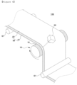
FIGS. 4 and5 are a cross-sectional view and a perspective view schematically showing an embodiment of the electrode etching apparatus of the present invention,FIG. 6 is a perspective view schematically showing an embodiment of the electrode etching apparatus of the present invention, andFIG. 7 is a cross-sectional view schematically showing a usage state of the electrode etching apparatus of the present invention. - An electrode etching (ablation)
apparatus 100 of the present invention includes an electrodeassembly support roller 10, and alaser irradiation device 20, as shown inFIGS. 4 to 7 . - The electrode
assembly support roller 10 includes two or morecylindrical roller segments 11, and the two or morecylindrical roller segments 11 are coupled to theroller segment 11 adjacent to one shaft forfixation 15 in a spaced-apart manner. - The
laser irradiation device 20 is disposed to be able to irradiate a separated space formed between thecylindrical roller segments 11 with a laser beam. - Because the
electrode etching apparatus 100 of the present invention is configured such that the electrodeassembly support roller 10 includes two or morecylindrical roller segments 11, as shown inFIG. 3(a) , there is a feature that can prevent damage to the electrodeassembly support roller 10 and the resulting damage to the electrode assembly, which may occur when theelectrode assembly 50 is damaged. In addition, as shown inFIG. 3(b) , when the output adjustment of thelaser irradiation device 20 fails, there is a feature that can prevent damage to the electrodeassembly support roller 10 and the resulting damage to the electrode assembly, which may occur due to the laser beam passing through theelectrode assembly 50. - In an embodiment of the invention, one or more of the
cylindrical roller segments 11 have a structure that can be moved and fixed along the shaft forfixation 15. As described above, when one or more of thecylindrical roller segments 11 are configured to be movable and fixed, it is possible to provide an advantage capable of utilizing theelectrode etching apparatus 100 to correspond to theelectrode assemblies 50 having various sizes. - The
cylindrical roller segment 11 that can be moved and fixed may be onecylindrical roller segment 11 located on the outermost side of one end of thesupport roller 10, or may be twocylindrical roller segments 11 located on the outermost side of both ends of thesupport roller 11, or may be the entirecylindrical roller segments 11 that make up thesupport roller 10. - In an embodiment of the present invention, one or more
cylindrical roller segments 11 that can be moved and fixed are movable and can be fixed in accordance with the width of theelectrode assembly 50. That is, since the separated space between thecylindrical roller segments 11 to be irradiated with the laser beam also changes according to the width of theelectrode assembly 50, this configuration enables adjustment of the position of thecylindrical roller segments 11 in accordance with this change. - In an embodiment of the invention, the shaft for
fixation 15 can be configured as a rotary shaft. When the shaft forfixation 15 is configured as a rotary shaft as described above, there is provided an advantage in which thecylindrical roller segment 11 that constitutes thesupport roller 10 can be rotated, and theelectrode assembly 50 to be fed can travel, while being more smoothly supported. - In an embodiment of the present invention, the rotary shaft can be configured to rotate passively while coming into contact with the
electrode assembly 50 to be fed or rotated by a driving device provided separately. - In an embodiment of the present invention, one or more
cylindrical roller segments 11 among thecylindrical roller segments 11 may have one or more suction holes 12 on a circumferential surface. - The
cylindrical roller segment 11 having one or more suction holes may be onecylindrical roller segment 11 located at the outermost side of one end of thesupport roller 10, may be the two outermostcylindrical roller segments 11 located at the outermost side of both ends of thesupport roller 10, or may be the entirecylindrical roller segments 11 that make up thesupport roller 10. - In the present invention, the
electrode assembly 50 may be made up of, for example, acurrent collector sheet 51, and electrode active material layers 52 laminated on the upper side or lower side of the current collector sheet, or both the upper and lower sides. Theelectrode etching apparatus 100 of the present invention can perform a function of irradiating a laser beam to etch and remove the electrodeactive material layer 52. - For example, the
electrode etching apparatus 100 of the present invention can preferably be used to etch (ablate) and remove the sliding portion formed at the end portion when coating the electrode active material, and can also be used to remove the electrode active material from thecurrent collector sheet 51 to form a non-coating portion. - Therefore, the suction holes 12 can perform a function of sucking and removing the electrode active material particles generated when the electrode active material is removed. In addition, the suction holes 12 can also perform a function of absorbing and fixing the lower side of the
electrode assembly 50. - In an embodiment of the invention, the suction holes 12 can be connected with a suction device through the internal space of the cylindrical roller segment. At this time, the
suction hole 12 and the suction device may be connected by an exhaust pipe. Further, the exhaust pipe may pass through the internal space of the shaft forfixation 15 and be connected to the suction device, and the internal space of the shaft forfixation 15 itself can also serve as the exhaust pipe. - The
suction hole 12 may be formed entirely on the circumferential surface of thecylindrical roller segment 11. However, it is not formed only in this manner, but can be formed in various forms in consideration of the type of the object to be etched, the suction efficiency and the like. - In an embodiment of the present invention, the
electrode etching apparatus 100 may further include a travelingequipment 60 that allows the electrode assembly to travel while forming an internal angle of 70 degrees to 160 degrees, preferably 80 degrees to 130 degrees, and more preferably 85 degrees to 95 degrees around thesupport roller 10, as shown inFIG. 6 . - When the
electrode assembly 50 travels while forming the internal angle as described above, since a curved portion formed in theelectrode assembly 50 forms a large contact area with thesupport roller 10, the curved portion can be more stably supported by thesupport roller 50 and thus is preferable. - In an embodiment of the present invention, the traveling
equipment 60 may be configured to include travelingrollers 61 located forward and rearward of thesupport rollers 50 on the basis of the movement direction of the electrode assembly. - The traveling
roller 61 may be passively rotated while coming into contact with theelectrode assembly 50 to be fed, or may be rotated by a driving device provided separately. - In an embodiment of the present invention, the
laser irradiation device 20 may be located above the outer side of theelectrode assembly 50 whose inner side is supported by the circumferential surface of thesupport roller 50 by a surface contact. That is, thelaser irradiation device 20 can irradiate theelectrode assembly 50 with a laser beam at the same position as described above to perform etching. - In an embodiment of the present invention, the
laser irradiation device 20 can be installed to be movable along an axis parallel to the shaft forfixation 15 of the cylindrical roller segment. That is, in the present invention, although it is possible to form a separated space irradiated with a laser beam by movement of thecylindrical roller segment 11, when thelaser irradiation device 20 can be moved as described above, it is preferable because theelectrode etching apparatus 100 in accordance with the size of theelectrode assembly 50 can be more easily set. - In an embodiment of the present invention, the
laser irradiation device 20 may be fixed to aguide rail 21 located on an axis parallel to the shaft for fixation of thecylindrical roller segment 51, as shown inFIGS. 4 and7 . For example, a protrusion is formed in one of theguide rail 21 and thelaser irradiation device 20, and aguide groove 22 is provided on the other thereof so that thelaser irradiation device 20 can move by sliding. Thus, they can be coupled together to form the sliding portion. - In the present invention, as the
laser irradiation device 20, a known laser irradiation device that can be used for etching (ablation) of the material can be used without limitation. - In an embodiment of the present invention, the
electrode assembly 50 may have an inner side formed of thecurrent collector sheet 51, and an outer side formed of the electrodeactive material layer 52. - In an embodiment of the present invention, the
electrode etching apparatus 100 can be used for etching the electrodeactive material layer 52 in an electrode assembly including the electrodeactive material layer 52 laminated on thecurrent collector sheet 51. - In the
electrode etching apparatus 100 of the present invention, except for the configurations specified above, various components known in the field can be adopted without limitation, and structures of each component included in theelectrode etching apparatus 100 can also be manufacture with structures known in this field when including relevant technical features. - Although the present invention has been described in relation to the preferred embodiment as described above, various modifications and variations may be made without departing from the spirit and scope of the invention. Accordingly, the appended claims shall include such modifications or variations insofar as they fall within the spirit of the present invention.
[Description of symbols] 10: Electrode assembly support roller 11: Cylindrical roller segment 12: Suction hole 15: Shaft for fixation 20: Laser etching apparatus 21: Guide rail 22: Guide groove 50: Electrode assembly 51: Current collector sheet 52: Electrode active material layer 53: Sliding portion 60: Traveling equipment 61: Traveling roller 100: Electrode etching apparatus
Claims (15)
- An electrode etching apparatus, comprising:an electrode assembly support roller; anda laser irradiation device,wherein the electrode assembly support roller includes two or more cylindrical roller segments, and the two or more cylindrical roller segments are coupled to one shaft for fixation in a spaced-apart manner with a adjacent roller segment, andthe laser irradiation device is located to be able to irradiate a separated space formed between the cylindrical roller segments with a laser beam.
- The electrode etching apparatus according to claim 1, wherein one or more of the cylindrical roller segments are able to be moved and fixed along a shaft for fixation.
- The electrode etching apparatus according to claim 2, wherein one or more cylindrical roller segments that are able to be moved and fixed are one cylindrical roller segment located on an outermost side of one end of the support roller, two cylindrical roller segments located on the outermost side of both ends of the support roller, or the entire cylindrical roller segments that make up the support roller.
- The electrode etching apparatus according to claim 2, wherein one or more cylindrical roller segments that are able to be moved and fixed are moved and fixed in accordance with the width of the electrode assembly.
- The electrode etching apparatus according to claim 1, wherein the shaft for fixation is a rotary shaft.
- The electrode etching apparatus according to claim 1, wherein one or more cylindrical roller segments among the cylindrical roller segments are provided with one or more suction holes on a circumferential surface thereof.
- The electrode etching apparatus according to claim 6,
wherein the cylindrical roller segment having one or more suction holes is one cylindrical roller segment located at the outermost side of one end of the support roller, the two cylindrical roller segments located at the outermost side of both ends of the support roller, or the entire cylindrical roller segments that make up the support roller. - The electrode etching apparatus according to claim 6, wherein the suction hole is connected to a suction device through an internal space of the cylindrical roller segment.
- The electrode etching apparatus according to claim 1, wherein the electrode etching apparatus further comprises a traveling equipment that causes the electrode assembly to travel, while forming an internal angle of 70 to 160 degrees around the support roller.
- The electrode etching apparatus according to claim 9, wherein the traveling equipment comprises traveling rollers located in front and behind the support rollers on the basis of a movement direction of the electrode assembly.
- The electrode etching apparatus according to claim 1, wherein the laser irradiation device is located above the outer side of the electrode assembly whose inner side is supported by the circumferential surface of the support roller by a surface contact.
- The electrode etching apparatus according to claim 11, wherein the laser irradiation device is installed to be movable along an axis parallel to the shaft for fixation of the cylindrical roller segment.
- The electrode etching apparatus according to claim 12, wherein the laser irradiation device is fixed to a guide rail located on an axis parallel to the shaft for fixation of the cylindrical roller segment.
- The electrode etching apparatus according to claim 11, wherein the electrode assembly has an inner side formed of a current collector sheet, and an outer side formed of an electrode active material layer.
- The electrode etching apparatus according to claim 1, wherein the electrode etching apparatus is used for etching the electrode active material layer in an electrode assembly including the electrode active material layer laminated on the current collector sheet.
Applications Claiming Priority (2)
| Application Number | Priority Date | Filing Date | Title |
|---|---|---|---|
| KR1020210149907A KR20230064384A (en) | 2021-11-03 | 2021-11-03 | Electrode etching device |
| PCT/KR2022/017065 WO2023080646A1 (en) | 2021-11-03 | 2022-11-02 | Electrode etching apparatus |
Publications (2)
| Publication Number | Publication Date |
|---|---|
| EP4336578A1 true EP4336578A1 (en) | 2024-03-13 |
| EP4336578A4 EP4336578A4 (en) | 2024-12-18 |
Family
ID=86241843
Family Applications (1)
| Application Number | Title | Priority Date | Filing Date |
|---|---|---|---|
| EP22890377.9A Pending EP4336578A4 (en) | 2021-11-03 | 2022-11-02 | ELECTRODE ETCHING DEVICE |
Country Status (6)
| Country | Link |
|---|---|
| US (1) | US20240269777A1 (en) |
| EP (1) | EP4336578A4 (en) |
| JP (1) | JP7732171B2 (en) |
| KR (1) | KR20230064384A (en) |
| CN (1) | CN117480626A (en) |
| WO (1) | WO2023080646A1 (en) |
Cited By (1)
| Publication number | Priority date | Publication date | Assignee | Title |
|---|---|---|---|---|
| WO2025078959A1 (en) * | 2023-10-10 | 2025-04-17 | G.D S.P.A. | Apparatus for forming incisions in an electrode precursor and method for forming incisions in an electrode precursor |
Family Cites Families (10)
| Publication number | Priority date | Publication date | Assignee | Title |
|---|---|---|---|---|
| JP4701463B2 (en) * | 1998-11-05 | 2011-06-15 | パナソニック株式会社 | Method for removing active material from battery electrode plate |
| JP4233670B2 (en) | 1999-03-01 | 2009-03-04 | パナソニック株式会社 | Method for producing non-aqueous electrolyte secondary battery |
| JP2015031669A (en) * | 2013-08-07 | 2015-02-16 | トヨタ自動車株式会社 | Electrode sheet inspection system |
| KR101761973B1 (en) * | 2013-11-29 | 2017-07-26 | 주식회사 엘지화학 | Notching apparatus of laser |
| KR101571390B1 (en) * | 2014-06-09 | 2015-11-24 | 변영희 | Apparatus for drilling continuously using laser |
| JP6817746B2 (en) * | 2016-08-19 | 2021-01-20 | 株式会社Screenホールディングス | Adsorption roller, coating equipment and membrane / electrode assembly manufacturing equipment |
| KR101958881B1 (en) * | 2018-12-06 | 2019-03-15 | (주)하나기술 | Electrode notching system for secondary battery |
| KR102803271B1 (en) * | 2019-10-24 | 2025-05-07 | 주식회사 엘지에너지솔루션 | A manufacturing method and equipment for Electrode using laser etching |
| KR102807488B1 (en) * | 2019-12-23 | 2025-05-13 | 주식회사 엘지에너지솔루션 | Manufacturing Apparatus and Manufacturing Method of Electrode for Secondary Battery using Laser, and Electrode for Secondary Battery Manufactured by the Same |
| KR102158708B1 (en) * | 2020-06-10 | 2020-09-22 | 주식회사 디에이테크놀로지 | Drum Type Pattern Jig for Laser Notching Process of Electrode Film for Secondary Battery, And Laser Notching System Having the Pattern Jig |
-
2021
- 2021-11-03 KR KR1020210149907A patent/KR20230064384A/en active Pending
-
2022
- 2022-11-02 US US18/570,191 patent/US20240269777A1/en active Pending
- 2022-11-02 EP EP22890377.9A patent/EP4336578A4/en active Pending
- 2022-11-02 CN CN202280040370.0A patent/CN117480626A/en active Pending
- 2022-11-02 WO PCT/KR2022/017065 patent/WO2023080646A1/en not_active Ceased
- 2022-11-02 JP JP2023575379A patent/JP7732171B2/en active Active
Cited By (1)
| Publication number | Priority date | Publication date | Assignee | Title |
|---|---|---|---|---|
| WO2025078959A1 (en) * | 2023-10-10 | 2025-04-17 | G.D S.P.A. | Apparatus for forming incisions in an electrode precursor and method for forming incisions in an electrode precursor |
Also Published As
| Publication number | Publication date |
|---|---|
| EP4336578A4 (en) | 2024-12-18 |
| KR20230064384A (en) | 2023-05-10 |
| US20240269777A1 (en) | 2024-08-15 |
| JP7732171B2 (en) | 2025-09-02 |
| CN117480626A (en) | 2024-01-30 |
| WO2023080646A1 (en) | 2023-05-11 |
| JP2024523193A (en) | 2024-06-28 |
Similar Documents
| Publication | Publication Date | Title |
|---|---|---|
| US20240246177A1 (en) | Electrode Manufacturing Device Used For Laser Notching Of Electrode | |
| KR102182307B1 (en) | Device for Manufacturing Electrode Comprising Pattern Zig and Scrap Outlet Portion | |
| JP6690486B2 (en) | Electrode manufacturing equipment | |
| KR102168229B1 (en) | An electrode for an electrochemical device and a method for manufacturing the same | |
| US20120196167A1 (en) | Electrode assembly for a battery and method for manufacturing same | |
| US20200206965A1 (en) | Apparatus and method for notching electrode sheet | |
| KR20230109896A (en) | Electrode tab notching device | |
| KR102224911B1 (en) | Leveling apparatus for preventing curling of pouch type secondary battery | |
| US20240269777A1 (en) | Electrode Etching Apparatus | |
| KR20210144311A (en) | The Electrode, The Secondary Battery, The Apparatus And The Method For Manufacturing Electrode | |
| KR20230008975A (en) | Electrode and method for manufacturing the same | |
| EP4207340A1 (en) | Method for manufacturing electrode and electrode manufacturing system used in same | |
| KR20230173036A (en) | Laser notching device | |
| CN118696425A (en) | Method and apparatus for producing a strip-shaped electrode | |
| JP2018142532A (en) | Cutting device, cutting method, and method of manufacturing electrode | |
| KR102877574B1 (en) | Manufacturing method and apparatus for electrode assemblyused | |
| KR20180113335A (en) | Winding Type-Electrode Assembly Having Prismatic Cross-Sectional Structure | |
| KR20210128123A (en) | Secondary battery electrode | |
| KR20210059057A (en) | Electrode for secondary battery and method of manufacturing the same | |
| KR20240111595A (en) | Electrode manufacturing apparatus and method | |
| US20210273266A1 (en) | Energy storage device | |
| US20260108987A1 (en) | Laser notching apparatus and rechargeable battery manufacturing system | |
| US20250187240A1 (en) | Mold and injection molding method | |
| EP4589233B1 (en) | Electrode manufacturing system and method for manufacturing an electrode | |
| US20260135078A1 (en) | Rolling apparatus for manufacturing electrode plate |
Legal Events
| Date | Code | Title | Description |
|---|---|---|---|
| STAA | Information on the status of an ep patent application or granted ep patent |
Free format text: STATUS: THE INTERNATIONAL PUBLICATION HAS BEEN MADE |
|
| PUAI | Public reference made under article 153(3) epc to a published international application that has entered the european phase |
Free format text: ORIGINAL CODE: 0009012 |
|
| STAA | Information on the status of an ep patent application or granted ep patent |
Free format text: STATUS: REQUEST FOR EXAMINATION WAS MADE |
|
| 17P | Request for examination filed |
Effective date: 20231204 |
|
| AK | Designated contracting states |
Kind code of ref document: A1 Designated state(s): AL AT BE BG CH CY CZ DE DK EE ES FI FR GB GR HR HU IE IS IT LI LT LU LV MC ME MK MT NL NO PL PT RO RS SE SI SK SM TR |
|
| A4 | Supplementary search report drawn up and despatched |
Effective date: 20241120 |
|
| RIC1 | Information provided on ipc code assigned before grant |
Ipc: B23K 37/04 20060101ALI20241114BHEP Ipc: B23K 37/047 20060101ALI20241114BHEP Ipc: B23K 26/362 20140101ALI20241114BHEP Ipc: H01M 4/04 20060101AFI20241114BHEP |
|
| DAV | Request for validation of the european patent (deleted) | ||
| DAX | Request for extension of the european patent (deleted) | ||
| STAA | Information on the status of an ep patent application or granted ep patent |
Free format text: STATUS: EXAMINATION IS IN PROGRESS |
|
| 17Q | First examination report despatched |
Effective date: 20250902 |
|
| GRAP | Despatch of communication of intention to grant a patent |
Free format text: ORIGINAL CODE: EPIDOSNIGR1 |
|
| STAA | Information on the status of an ep patent application or granted ep patent |
Free format text: STATUS: GRANT OF PATENT IS INTENDED |
|
| INTG | Intention to grant announced |
Effective date: 20260304 |