EP4336552B1 - Composant électronique comprenant un fluide diphasique pour évacuer les calories thermiques des semi-conducteurs dudit composant électronique - Google Patents
Composant électronique comprenant un fluide diphasique pour évacuer les calories thermiques des semi-conducteurs dudit composant électronique Download PDFInfo
- Publication number
- EP4336552B1 EP4336552B1 EP23187170.8A EP23187170A EP4336552B1 EP 4336552 B1 EP4336552 B1 EP 4336552B1 EP 23187170 A EP23187170 A EP 23187170A EP 4336552 B1 EP4336552 B1 EP 4336552B1
- Authority
- EP
- European Patent Office
- Prior art keywords
- electronic component
- phase fluid
- volume
- layer
- phase
- Prior art date
- Legal status (The legal status is an assumption and is not a legal conclusion. Google has not performed a legal analysis and makes no representation as to the accuracy of the status listed.)
- Active
Links
Images

Classifications
-
- H—ELECTRICITY
- H05—ELECTRIC TECHNIQUES NOT OTHERWISE PROVIDED FOR
- H05K—PRINTED CIRCUITS; CASINGS OR CONSTRUCTIONAL DETAILS OF ELECTRIC APPARATUS; MANUFACTURE OF ASSEMBLAGES OF ELECTRICAL COMPONENTS
- H05K7/00—Constructional details common to different types of electric apparatus
- H05K7/20—Modifications to facilitate cooling, ventilating, or heating
- H05K7/2029—Modifications to facilitate cooling, ventilating, or heating using a liquid coolant with phase change in electronic enclosures
- H05K7/20327—Accessories for moving fluid, for connecting fluid conduits, for distributing fluid or for preventing leakage, e.g. pumps, tanks or manifolds
-
- H—ELECTRICITY
- H10—SEMICONDUCTOR DEVICES; ELECTRIC SOLID-STATE DEVICES NOT OTHERWISE PROVIDED FOR
- H10W—GENERIC PACKAGES, INTERCONNECTIONS, CONNECTORS OR OTHER CONSTRUCTIONAL DETAILS OF DEVICES COVERED BY CLASS H10
- H10W40/00—Arrangements for thermal protection or thermal control
- H10W40/70—Fillings or auxiliary members in containers or in encapsulations for thermal protection or control
- H10W40/73—Fillings or auxiliary members in containers or in encapsulations for thermal protection or control for cooling by change of state
-
- B—PERFORMING OPERATIONS; TRANSPORTING
- B64—AIRCRAFT; AVIATION; COSMONAUTICS
- B64D—EQUIPMENT FOR FITTING IN OR TO AIRCRAFT; FLIGHT SUITS; PARACHUTES; ARRANGEMENT OR MOUNTING OF POWER PLANTS OR PROPULSION TRANSMISSIONS IN AIRCRAFT
- B64D47/00—Equipment not otherwise provided for
-
- H—ELECTRICITY
- H05—ELECTRIC TECHNIQUES NOT OTHERWISE PROVIDED FOR
- H05K—PRINTED CIRCUITS; CASINGS OR CONSTRUCTIONAL DETAILS OF ELECTRIC APPARATUS; MANUFACTURE OF ASSEMBLAGES OF ELECTRICAL COMPONENTS
- H05K7/00—Constructional details common to different types of electric apparatus
- H05K7/20—Modifications to facilitate cooling, ventilating, or heating
- H05K7/2029—Modifications to facilitate cooling, ventilating, or heating using a liquid coolant with phase change in electronic enclosures
- H05K7/20318—Condensers
-
- H—ELECTRICITY
- H10—SEMICONDUCTOR DEVICES; ELECTRIC SOLID-STATE DEVICES NOT OTHERWISE PROVIDED FOR
- H10W—GENERIC PACKAGES, INTERCONNECTIONS, CONNECTORS OR OTHER CONSTRUCTIONAL DETAILS OF DEVICES COVERED BY CLASS H10
- H10W40/00—Arrangements for thermal protection or thermal control
- H10W40/70—Fillings or auxiliary members in containers or in encapsulations for thermal protection or control
- H10W40/73—Fillings or auxiliary members in containers or in encapsulations for thermal protection or control for cooling by change of state
- H10W40/735—Fillings or auxiliary members in containers or in encapsulations for thermal protection or control for cooling by change of state by melting or evaporation of solids
-
- H—ELECTRICITY
- H10—SEMICONDUCTOR DEVICES; ELECTRIC SOLID-STATE DEVICES NOT OTHERWISE PROVIDED FOR
- H10W—GENERIC PACKAGES, INTERCONNECTIONS, CONNECTORS OR OTHER CONSTRUCTIONAL DETAILS OF DEVICES COVERED BY CLASS H10
- H10W40/00—Arrangements for thermal protection or thermal control
- H10W40/20—Arrangements for cooling
- H10W40/25—Arrangements for cooling characterised by their materials
- H10W40/255—Arrangements for cooling characterised by their materials having a laminate or multilayered structure, e.g. direct bond copper [DBC] ceramic substrates
Definitions
- the present application relates to an electronic component comprising means for direct cooling of the semiconductors of said electronic component, in the form of a two-phase fluid circulating in contact with said semiconductors.
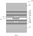
- This electronic component 10 comprises a stack of copper layers 12a-d alternating with layers of a ceramic substrate 14a-c.
- the copper layers 12a, 12d are the outer layers of the stack.
- On one of the substrate layers 14b at least one semiconductor 16 is arranged.
- the semiconductor 16 is electrically connected to the adjacent copper layers 12b, 12c, via solders 22.
- the semiconductor 16 is protected by a layer of epoxy resin 18, arranged between the substrate layer 14b on which the semiconductor 16 is arranged and an adjacent copper layer 12c.
- the electronic component 10 has a structure known by the English term "Direct Bonded Copper".
- heat sinks 20 are fixed to the electronic component 10, via a thermal paste or directly soldered onto the outer copper layers, on either side of the stack of layers. Due to the fact from the position of the heat sinks 20, the thermal losses emitted by the semiconductor 16 must be evacuated through the layers of copper 12a-d and ceramic 14a-c, which generates inefficiencies since said layers have a non-negligible thermal resistance.
- heat sinks have a significant weight, which impacts the weight of the electronic component.
- the present invention aims to propose an alternative solution to this method of cooling semiconductors in electronic components.
- US2019/096780 A1 discloses an electronic component cooled by a two-phase fluid.
- the subject of the invention is an electronic component comprising a stack of at least first and second layers of electrically conductive material, alternating with at least a third layer of electrically non-conductive material, said third layer being arranged between said first and second layers, and comprising a first face arranged opposite and at a distance from the second layer and a second face opposite the first face arranged opposite and in contact with the first layer, a volume being defined between the first face of the third layer and the second layer.
- the electronic component comprises at least one semiconductor arranged in said volume on the first face of the third layer and cooling means taking the form of a two-phase fluid filling said volume.
- the electronic component according to the invention is devoid of an epoxy resin layer, as well as a heat sink.
- the electronic component according to the invention has a reduced weight compared to the electronic component of the prior art, since said electronic component is devoid of heat sinks, which have a significant impact on the weight of said electronic component.
- the electronic component according to the invention has improved performance, in particular thanks to more efficient cooling of the semiconductors, which allows an extension of their lifespan, but also a better efficiency of the electronic component.
- the installation of the electronic component according to the invention is easier, since it is less bulky.
- the two-phase fluid is a liquid-gaseous two-phase fluid.
- the volume has an inlet and an outlet
- the electronic component comprises a reservoir of two-phase fluid, a pump fluidly connected between the reservoir and the inlet of said volume, the two-phase fluid circulating between the inlet and the outlet of said volume, and a condenser fluidly connected between the outlet of said volume and the inlet of the reservoir.
- liquid-gaseous two-phase fluid is included in the following list: dielectric oil, purified water, methanol, acetone, R1234 refrigerant gas and FC-7 oil.
- the two-phase fluid is a solid-liquid two-phase fluid.
- the electronic component comprises a housing encapsulating the first, second and third layers, said housing being filled with the two-phase fluid and made of thermally conductive material.
- the solid-liquid two-phase fluid is included in the following list: lauric acid, pure gallium and INERTEK microcapsules.
- the electronic component is a power converter, or a switch, or an inverter, or a voltage adapter, or a current adapter.
- the invention also relates to an electronic system comprising at least one electronic component according to the invention, as well as an aircraft comprising at least one electronic system according to the invention.
- This electronic component 30 comprises a stack of layers of electrically conductive material 32a-d, such as copper, alternating with layers of electrically non-conductive material 34a-c, for example a ceramic substrate.
- a first and a fourth copper layer 32a, 32d are the outer layers of the stack.
- the ceramic layers 34a-34c are only inner layers of the stack.
- the first ceramic layer 34a is disposed between the first and second copper layers 32a, 32b;
- the second ceramic layer 34b is disposed between the second and third copper layers 32b, 32c;
- the third ceramic layer 34c is disposed between the third and fourth copper layers 32c, 32d.
- the electronic component 30 may comprise more or fewer copper layers 32a-d or ceramic layers 34a-c than those shown.
- the second ceramic layer 34b has a first face F1 arranged opposite and in contact with the second copper layer 32b, and an opposite second face F2 arranged opposite and at a distance from the third copper layer 32c.
- the layers 32a, 34a, 32b, 34b are stacked in contact with each other, in this order, without a space between said layers, and the layers 32c, 34c, 32d are stacked in contact with each other, in this order, without a space between said layers, while a space is present between the layers 34b and 32c.
- the semiconductor 36 is thus arranged in the volume 38.
- the semiconductor 36 is electrically connected to the second and third copper layers 32b, 32c, via solders 42.
- the electronic component 30 thus has a structure known by the Anglo-Saxon term "Direct Bonded Copper".
- Volume 38 of this electronic component 30 is free of epoxy resin.
- the electronic component 30 comprises cooling means arranged at least partly in the volume 38.
- These cooling means take the form of a two-phase fluid which fills the volume 38.
- the semiconductor 36 is immersed in the two-phase fluid which fills the volume 38.
- the other surfaces of the semiconductor 36 are in contact with the two-phase fluid.
- the two-phase fluid is arranged in the volume 38, instead of the epoxy resin used according to the prior art shown in the Figure 1 .
- a two-phase fluid is a phase-changing material that, depending on temperature, can change from a phase in a first state to a phase in a second state, and vice versa.
- the two-phase fluid can be a liquid-gas two-phase fluid, or a solid-liquid two-phase fluid.
- This electronic component 30 does not have a heat sink.
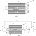
- the two-phase fluid is a liquid-gaseous two-phase fluid.
- the liquid-gaseous two-phase fluid may be a dielectric oil, such as HFE-7000 (Hydrofluoroether) or NOVEC TM 7000, purified water, methanol, acetone, R1234 refrigerant gas, or FC-7X oil.
- the two-phase fluid is configured to be in a liquid phase when the temperature is below a predetermined phase change temperature, and to change to a gaseous phase when the temperature becomes higher than the predetermined phase change temperature.
- this two-phase fluid is configured to change back to the liquid phase when the temperature becomes lower than the predetermined phase change temperature.
- the electronic component 30 comprises a reservoir 50 of two-phase fluid comprising an inlet 50a and an outlet 50b.
- the two-phase fluid is in its liquid state.
- the outlet 50b of the reservoir 50 is fluidically connected to a pump 56, via a pipe 54a.
- the pump 56 is also fluidically connected to an inlet 38a of the volume 38, via a pipe 54b.
- the two-phase fluid circulates between the inlet 38a and an outlet 38b of the volume 38.
- the pump 56 makes it possible to pressurize the two-phase fluid from the reservoir 50, so that the two-phase fluid is sent and circulates correctly in the volume 38.
- the circulation of the two-phase fluid is represented by the arrows F.
- the electronic component 30 comprises a condenser 52 fluidically connected to the outlet 38b of the volume 38 and to the inlet 50a of the reservoir 50, respectively via pipes 54c, 54d.
- the temperature of the semiconductor 36 increases, and the two-phase fluid circulating between the inlet 38a and the outlet 38b of the volume 38 will change from its liquid phase to its gaseous phase in order to absorb this increase in temperature and cool said semiconductor 36. More precisely, the change in phase of the two-phase fluid makes it possible to extract the thermal calories emitted by the semiconductor 36 in operation.
- the condenser 52 When the two-phase fluid in gaseous form passes into the condenser 52, the latter passes from its gaseous state to the liquid state, before being returned to the reservoir 50.
- the condenser 52 thus makes it possible to cool the two-phase fluid, which has absorbed the thermal calories from the semiconductor 36.
- the condenser 52 may be in contact with the ambient air, or in contact with a secondary cooling loop.
- the two-phase fluid is a solid-liquid two-phase fluid.
- the solid-liquid two-phase fluid may be lauric acid, such as coconut oil (phase change temperature around 25°C), pure gallium (phase change temperature around 30°C), or INERTEK microcapsules (phase change temperature ranging from 5°C to 28°C depending on the phase change material microencapsulated).
- the two-phase fluid is configured to be in a solid phase when the temperature is below a predetermined phase change temperature, and to transition to a liquid phase when the temperature becomes higher than the predetermined phase change temperature.
- this two-phase fluid is configured to transition back to the solid phase when the temperature becomes lower than the predetermined phase change temperature.
- the electronic component 30 comprises a housing 60 encapsulating the copper layers 32a-d and the ceramic layers 34a-c.
- the housing 60 and in particular the volume 38 between the second ceramic layer 34b and the third copper layer 32c, around the semiconductor 36, is filled with two-phase fluid.
- the two-phase fluid In the housing 60, the two-phase fluid is in its solid state. In the solid phase, the two-phase fluid provides a function of immobilizing and protecting the semiconductor 36.
- the housing 60 is made of a thermally conductive material, for example aluminum or copper.
- the temperature of the semiconductor 36 increases, and the two-phase fluid present in the volume 38 will change from its solid phase to its liquid phase in order to extract the thermal calories emitted by the semiconductor 36 in operation and to absorb this increase in temperature.
- the housing 60 is configured to thermally dissipate the calories absorbed by the two-phase fluid during the phase change.
- the thermal calories are then evacuated by conduction in the housing 60, then by natural convection or radiation from the housing 60 into the environment of the electronic component 30.
- FIG. 5 represents an aircraft 70 in which at least one electronic system 72 is integrated comprising at least one electronic component 30 as described above.
- the electronic component 30 may be, in a non-limiting manner, a power converter, a switch, an inverter or a voltage or current adapter, and more generally any electronic component comprising at least one so-called power semiconductor.
Landscapes
- Engineering & Computer Science (AREA)
- Microelectronics & Electronic Packaging (AREA)
- Physics & Mathematics (AREA)
- Thermal Sciences (AREA)
- Aviation & Aerospace Engineering (AREA)
- Cooling Or The Like Of Semiconductors Or Solid State Devices (AREA)
Description
- La présente demande se rapporte à un composant électronique comprenant des moyens de refroidissement direct des semi-conducteurs dudit composant électronique, se présentant sous la forme d'un fluide diphasique circulant au contact desdits semi-conducteurs.
- Un composant électronique selon un mode de réalisation est présenté sur la
figure 1 . Ce composant électronique 10 comporte un empilement de couches de cuivre 12a-d alternées avec des couches d'un substrat en céramique 14a-c. Les couches de cuivre 12a, 12d sont les couches extérieures de l'empilement. Sur une des couches de substrat 14b, est disposé au moins un semi-conducteur 16. Le semi-conducteur 16 est connecté électriquement aux couches de cuivre 12b, 12c adjacentes, via des brasures 22. Le semi-conducteur 16 est protégé par une couche de résine époxy 18, agencée entre la couche de substrat 14b sur laquelle est disposé le semi-conducteur 16 et une couche de cuivre 12c adjacente. Le composant électronique 10 présente une structure connue sous les termes anglo-saxons "Direct Bonded Copper". - Afin de refroidir le semi-conducteur 16, des dissipateurs thermiques 20 sont fixés au composant électronique 10, via une pâte thermique ou directement brasés sur les couches de cuivre extérieures, de part et d'autre de l'empilement de couches . Du fait
de la position des dissipateurs thermiques 20, les pertes thermiques émises par le semi-conducteur 16 doivent être évacuées à travers les couches de cuivre 12a-d et de céramique 14a-c, ce qui engendre des inefficacités puisque lesdites couches présentent une résistance thermique non négligeable. - En outre, de tels dissipateurs thermiques ont un poids non négligeable, qui impacte le poids du composant électronique.
- La présente invention vise à proposer une solution alternative à ce mode de refroidissement des semi-conducteurs des composants électroniques.
-
US2019/096780 A1 divulgue un composant électronique refroidi par un fluide diphasique. - A cet effet, l'invention a pour objet un composant électronique comprenant un empilement d'au moins des première et deuxième couches de matériau conducteur électrique, alternées avec au moins une troisième couche de matériau non-conducteur électrique, ladite troisième couche étant agencée entre lesdites première et deuxième couches, et comprenant une première face disposée en regard et à distance de la deuxième couche et une deuxième face opposée à la première face disposée en regard et au contact de la première couche, un volume étant défini entre la première face de la troisième couche et la deuxième couche.
- Selon l'invention, le composant électronique comprend au moins un semi-conducteur disposé dans ledit volume sur la première face de la troisième couche et des moyens de refroidissement prenant la forme d'un fluide diphasique remplissant ledit volume.
- Ainsi, selon le composant électronique selon l'invention est dépourvu de couche de résine époxy, ainsi que de dissipateur thermique.
- Avantageusement, le composant électronique selon l'invention a un poids réduit par rapport au composant électronique de l'art antérieur, puisque ledit composant électronique est dépourvu de dissipateurs thermiques, qui ont un impact non négligeable sur le poids dudit composant électronique. En outre, le composant électronique selon l'invention présente des performances améliorées, notamment grâce à un refroidissement plus efficace des semi-conducteurs, ce qui permet un allongement de leur durée de vie, mais aussi un meilleur rendement du composant électronique. Avantageusement, l'installation du composant électronique selon l'invention est plus aisée, puisque moins volumineux.
- Selon une autre caractéristique, le fluide diphasique est un fluide diphasique liquide-gazeux. Selon cette caractéristique, le volume présente une entrée et une sortie, le composant électronique comporte un réservoir de fluide diphasique, une pompe connectée fluidiquement entre le réservoir et à l'entrée dudit volume, le fluide diphasique circulant entre l'entrée et la sortie dudit volume, et un condenseur connecté fluidiquement entre la sortie dudit volume et l'entrée du réservoir.
- Selon une autre caractéristique, le fluide diphasique liquide-gazeux est compris dans la liste suivante: une huile diélectrique, de l'eau purifiée, du méthanol, de l'acétone, du gaz réfrigérant R1234 et de l'huile FC-7.
- Selon un mode de réalisation qui ne fait pas partie de l'invention, le fluide diphasique est un fluide diphasique solide-liquide. Selon ce mode de réalisation qui ne fait pas partie de l'invention, le composant électronique comporte un boîtier encapsulant les première, deuxième et troisième couches, ledit boîtier étant rempli du fluide diphasique et réalisé en matériau conducteur thermique.
- Selon ce mode de réalisation qui ne fait pas partie de l'invention, le fluide diphasique solide-liquide est compris dans la liste suivante: de l'acide laurique, du gallium pur et des microcapsules INERTEK.
- Selon une autre caractéristique, le composant électronique est un convertisseur de puissance, ou un interrupteur, ou un onduleur, ou un adaptateur de tension, ou un adaptateur de courant. L'invention a également pour objet un système électronique comprenant au moins un composant électronique selon l'invention, ainsi qu'un aéronef comprenant au moins un système électronique selon l'invention.
- D'autres caractéristiques et avantages ressortiront de la description de l'invention qui va suivre, description donnée à titre d'exemple uniquement, en regard des dessins annexés parmi lesquels:
- la
Figure 1 est une vue schématique en coupe d'un composant électronique, qui illustre un mode de réalisation de l'art antérieur, - la
Figure 2 est une vue schématique en coupe d'un composant électronique, qui illustre un mode de réalisation de l'invention, - la
Figure 3 est une vue schématique en coupe d'un composant électronique, qui illustre un mode de réalisation de l'invention, - la
Figure 4 est une vue schématique en coupe d'un composant électronique, qui illustre un mode de réalisation qui ne fait pas partie de l'invention, et - la
Figure 5 est une vue schématique en perspective d'un aéronef comprenant un système électronique, lui-même comprenant un composant électronique, qui illustre un mode de réalisation de l'invention. - Un composant électronique 30 selon un mode de réalisation de l'invention est représenté sur la
figure 2 . Ce composant électronique 30 comporte un empilement de couches de matériau conducteur électrique 32a-d, tel que du cuivre, alternées avec des couches de matériau non conducteur électrique 34a-c, par exemple un substrat en céramique. Une première et une quatrième couches de cuivre 32a, 32d sont les couches extérieures de l'empilement. Les couches 34a-34c de céramique sont uniquement des couches intérieures à l'empilement. La première couche 34a de céramique est disposée entre les première et deuxième couches de cuivre 32a, 32b; la deuxième couche 34b de céramique est disposée entre les deuxième et troisième couches de cuivre 32b, 32c; la troisième couche 34c de céramique est disposée entre les troisième et quatrième couches de cuivre 32c, 32d. Bien entendu, le composant électronique 30 peut comprendre plus ou moins de couches 32a-d de cuivre ou de de couches 34a-c de céramique que celles représentées. - Entre la deuxième couche 34b de céramique et la troisième couche 32c de cuivre, un volume 38 est défini. La deuxième couche 34b de céramique présente une première face F1 disposée en regard et au contact de la deuxième couche 32b de cuivre, et une deuxième face F2 opposée disposée en regard et à distance de la troisième couche 32c de cuivre. Autrement dit, les couches 32a, 34a, 32b, 34b sont empilées au contact les unes sur les autres, dans cet ordre, sans espace entre lesdites couches, et les couches 32c, 34c, 32d sont empilées au contact les unes sur les autres, dans cet ordre, sans espace entre lesdites couches, tandis qu'un espace est présent entre les couches 34b et 32c.
- Sur la couche 34b de céramique, au niveau de la deuxième face F2, est disposé au moins un semi-conducteur 36. Le semi-conducteur 36 est ainsi disposé dans le volume 38. Le semi-conducteur 36 est connecté électriquement aux deuxième et troisième couches de cuivre 32b, 32c, via des brasures 42. Le composant électronique 30 présente ainsi une structure connue sous les termes anglo-saxons "Direct Bonded Copper".
- Le volume 38 de ce composant électronique 30 est dépourvu de résine époxy.
- Le composant électronique 30 comprend des moyens de refroidissement agencés au moins en partie dans le volume 38. Ces moyens de refroidissement prennent la forme d'un fluide diphasique qui remplit le volume 38. Autrement dit, le semi-conducteur 36 baigne dans le fluide diphasique qui remplit le volume 38. A l'exception de la surface du semi-conducteur 36 qui est brasée sur la couche 34b de céramique, les autres surfaces du semi-conducteur 36 sont au contact du fluide diphasique. Le fluide diphasique est disposé dans le volume 38, en lieu et place de la résine époxy utilisée selon l'art antérieur représenté sur la
figure 1 . - Un fluide diphasique est un matériau à changement de phase, qui en fonction de la température, peut changer d'une phase dans un premier état à une phase dans un second état, et inversement. Par exemple, le fluide diphasique peut être un fluide diphasique liquide-gazeux, ou un fluide diphasique solide-liquide.
- Ce composant électronique 30 est dépourvu de dissipateur thermique.
- Selon le mode de réalisation représenté sur la
figure 3 , le fluide diphasique est un fluide diphasique liquide-gazeux. De façon non limitative, le fluide diphasique liquide-gazeux peut être une huile diélectrique, de type HFE-7000 (Hydrofluoroether) ou NOVEC™ 7000, de l'eau purifiée, du méthanol, de l'acétone, du gaz réfrigérant R1234, ou encore de l'huile FC-7X. Le fluide diphasique est configuré pour être dans une phase liquide lorsque la température est inférieure à une température de changement de phase prédéterminée, et pour passer dans une phase gazeuse lorsque la température devient supérieure à la température de changement de phase prédéterminée. Lorsque le fluide diphasique est en phase gazeuse, ce fluide diphasique est configuré pour repasser en phase liquide lorsque la température redevient inférieure à la température de changement de phase prédéterminée. - Le composant électronique 30 comporte un réservoir 50 de fluide diphasique comprenant une entrée 50a et une sortie 50b. Dans le réservoir 50, le fluide diphasique est dans son état liquide. La sortie 50b du réservoir 50 est connectée fluidiquement à une pompe 56, via une canalisation 54a. La pompe 56 est également fluidiquement connectée à une entrée 38a du volume 38, via une canalisation 54b. Le fluide diphasique circule entre l'entrée 38a et une sortie 38b du volume 38. La pompe 56 permet de mettre sous pression le fluide diphasique issu du réservoir 50, pour que le fluide diphasique soit envoyé et circule correctement dans le volume 38. La circulation du fluide diphasique est représentée par les flèches F. Le composant électronique 30 comporte un condenseur 52 connecté fluidiquement à la sortie 38b du volume 38 et à l'entrée 50a du réservoir 50, respectivement via des canalisations 54c, 54d.
- Lors de l'utilisation du composant électronique 30, la température du semi-conducteur 36 augmente, et le fluide diphasique circulant entre l'entrée 38a et la sortie 38b du volume 38 va passer de sa phase liquide à sa phase gazeuse afin d'absorber cette hausse de température et refroidir ledit semi-conducteur 36. Plus précisément, le changement de phase du fluide diphasique permet d'extraire les calories thermiques émises par le semi-conducteur 36 en fonctionnement.
- Lorsque le fluide diphasique sous forme gazeuse passe dans le condenseur 52, ce dernier passe de son état gazeux à l'état liquide, avant d'être renvoyé dans le réservoir 50. Le condenseur 52 permet ainsi de refroidir le fluide diphasique, qui a absorbé les calories thermiques du semi-conducteur 36.
- Afin de refroidir le fluide diphasique, le condenseur 52 peut être au contact de l'air ambiant, ou au contact d'une boucle de refroidissement secondaire.
- Le fait d'utiliser un refroidissement par changement de phase du fluide diphasique permet, en contrôlant la pression à la sortie 38b du volume 38 du composant électronique 30, d'imposer la température de jonction du semi-conducteur 36.
- Selon le mode de réalisation représenté sur la
figure 4 , qui ne fait pas partie de l'invention, le fluide diphasique est un fluide diphasique solide-liquide. De façon non limitative, le fluide diphasique solide-liquide peut être de l'acide laurique, tel que de l'huile de coco (température de changement de phase aux alentours de 25°C), du gallium pur (température de changement de phase aux alentours de 30°C), ou encore des microcapsules INERTEK (température de changement de phase allant de 5°C à 28°C en fonction du matériau à changement de phase microencapsulé). Le fluide diphasique est configuré pour être dans une phase solide lorsque la température est inférieure à une température de changement de phase prédéterminée, et pour passer dans une phase liquide lorsque la température devient supérieure à la température de changement de phase prédéterminée. Lorsque le fluide diphasique est en phase liquide, ce fluide diphasique est configuré pour repasser en phase solide lorsque la température redevient inférieure à la température de changement de phase prédéterminée. - Le composant électronique 30 comporte un boîtier 60 encapsulant les couches 32a-d de cuivre et les couches 34a-c de céramique. Le boîtier 60, et notamment le volume 38 entre la deuxième couche 34b de céramique et la troisième couche 32c de cuivre, autour du semi-conducteur 36, est rempli de fluide diphasique. Dans le boîtier 60, le fluide diphasique est dans son état solide. En phase solide, le fluide diphasique assure une fonction d'immobilisation et de protection du semi-conducteur 36. Le boîtier 60 est réalisé en matériau conducteur thermique, par exemple en aluminium ou en cuivre.
- Lors de l'utilisation du composant électronique 30, la température du semi-conducteur 36 augmente, et le fluide diphasique présent dans le volume 38 va passer de sa phase solide à sa phase liquide afin d'extraire les calories thermiques émises par le semi-conducteur 36 en fonctionnement et d'absorber cette hausse de température. Ensuite, le boîtier 60 est configuré pour dissiper thermiquement les calories absorbées par le fluide diphasique lors du changement de phase. Les calories thermiques sont alors évacuées par conduction dans le boîtier 60, puis par convection naturelle ou radiation du boîtier 60 dans l'environnement du composant électronique 30.
- La
figure 5 représente un aéronef 70 dans lequel est intégré au moins un système électronique 72 comprenant au moins un composant électronique 30 tel que décrit ci-dessus. - Le composant électronique 30 peut être, de façon non limitative, un convertisseur de puissance, un interrupteur, un onduleur ou un adaptateur de tension ou de courant, et plus généralement tout composant électronique comprenant au moins un semi-conducteur dit de puissance.
Claims (5)
- Composant électronique (30) comprenant un empilement d'au moins des première et deuxième couches (32a-d) de matériau conducteur électrique, alternées avec au moins une troisième couche (34a-c) de matériau non-conducteur électrique, ladite troisième couche (34a-c) étant agencée entre lesdites première et deuxième couches (32a-d), et comprenant une première face (F2) disposée en regard et à distance de la deuxième couche (32c-d) et une deuxième face (F1) opposée à la première face (F2) disposée en regard et au contact de la première couche (32a-b), un volume (38) étant défini entre la première face (F2) de la troisième couche (34a-c) et la deuxième couche (32a-d), ledit composant électronique (30) comprenant au moins un semi-conducteur (36) disposé dans ledit volume (38) sur la première face (F2) de la troisième couche (34a-c), et caractérisé en ce que ledit composant électronique (30) comprend des moyens de refroidissement prenant la forme d'un fluide diphasique remplissant ledit volume (38), le fluide diphasique étant un fluide diphasique liquide-gazeux, le volume (38) présentant une entrée (38a) et une sortie (38b), et en ce que le composant électronique (30) comporte un réservoir (50) de fluide diphasique, une pompe (56) connectée fluidiquement entre le réservoir (50) et l'entrée (38a) dudit volume (38), le fluide diphasique circulant entre l'entrée (38a) et la sortie (38b) dudit volume (38), et un condenseur (52) connecté fluidiquement entre la sortie (38b) dudit volume (38) et l'entrée (50a) du réservoir (50).
- Composant électronique (30) selon la revendication 1, caractérisé en ce que le fluide diphasique liquide-gazeux est compris dans la liste suivante : une huile diélectrique, de l'eau purifiée, du méthanol, de l'acétone, du gaz réfrigérant R1234, et de l'huile FC-7.
- Composant électronique (30) selon l'une des revendications précédentes, caractérisé en ce que ledit composant électronique (30) est un convertisseur de puissance, ou un interrupteur, ou un onduleur, ou un adaptateur de tension, ou un adaptateur de courant.
- Système électronique (72) comprenant au moins un composant électronique (30) selon l'une des revendications 1 à 3.
- Aéronef (70) comprenant au moins un système électronique (72) selon la revendication 4.
Applications Claiming Priority (1)
| Application Number | Priority Date | Filing Date | Title |
|---|---|---|---|
| FR2209135 | 2022-09-12 |
Publications (2)
| Publication Number | Publication Date |
|---|---|
| EP4336552A1 EP4336552A1 (fr) | 2024-03-13 |
| EP4336552B1 true EP4336552B1 (fr) | 2025-03-12 |
Family
ID=84370656
Family Applications (1)
| Application Number | Title | Priority Date | Filing Date |
|---|---|---|---|
| EP23187170.8A Active EP4336552B1 (fr) | 2022-09-12 | 2023-07-24 | Composant électronique comprenant un fluide diphasique pour évacuer les calories thermiques des semi-conducteurs dudit composant électronique |
Country Status (3)
| Country | Link |
|---|---|
| US (1) | US12484195B2 (fr) |
| EP (1) | EP4336552B1 (fr) |
| CN (1) | CN117693156A (fr) |
Family Cites Families (8)
| Publication number | Priority date | Publication date | Assignee | Title |
|---|---|---|---|---|
| US20130224510A1 (en) * | 2012-02-29 | 2013-08-29 | General Electric Company | System including thermal interface material |
| US8967453B2 (en) * | 2012-03-21 | 2015-03-03 | GM Global Technology Operations LLC | Methods of bonding components for fabricating electronic assemblies and electronic assemblies including bonded components |
| US9918407B2 (en) * | 2016-08-02 | 2018-03-13 | Qualcomm Incorporated | Multi-layer heat dissipating device comprising heat storage capabilities, for an electronic device |
| DE102016218679A1 (de) * | 2016-09-28 | 2018-03-29 | Siemens Aktiengesellschaft | Elektronische Baugruppe mit einer Kühlvorrichtung, die mit einer Kühlflüssigkeit befüllbar ist |
| DE102017122053A1 (de) * | 2017-09-22 | 2019-03-28 | Infineon Technologies Ag | Magnetisches Phasenwechselmaterial zur Wärmeabfuhr |
| US11031317B2 (en) * | 2019-10-09 | 2021-06-08 | Toyota Motor Engineering & Manufacturing North America, Inc. | Direct bonded metal substrates with encapsulated phase change materials and electronic assemblies incorporating the same |
| US20210130076A1 (en) * | 2019-11-05 | 2021-05-06 | Amy BRINCKERHOFF | Automated pill dispenser and method of using the same |
| US11558957B2 (en) * | 2020-06-12 | 2023-01-17 | Raytheon Company | Shape memory thermal capacitor and methods for same |
-
2023
- 2023-07-24 EP EP23187170.8A patent/EP4336552B1/fr active Active
- 2023-08-25 CN CN202311083192.2A patent/CN117693156A/zh active Pending
- 2023-09-05 US US18/460,848 patent/US12484195B2/en active Active
Also Published As
| Publication number | Publication date |
|---|---|
| US12484195B2 (en) | 2025-11-25 |
| EP4336552A1 (fr) | 2024-03-13 |
| US20240090172A1 (en) | 2024-03-14 |
| CN117693156A (zh) | 2024-03-12 |
Similar Documents
| Publication | Publication Date | Title |
|---|---|---|
| CA1252508A (fr) | Installation de dissipation pour elements semi- conducteurs de puissance | |
| EP2844052B1 (fr) | Bloc convertisseur de puissance de véhicule électrique ou hybride | |
| EP2157016A2 (fr) | Système de refroidissement d'équipements électriques ou électroniques d'un aéronef | |
| CA2856833A1 (fr) | Dispositif electronique avec refroidissement par epanouisseur de chaleur a metal liquide | |
| CA2111507A1 (fr) | Systeme de dissipation de l'energie calorifique degagee par un composant electronique et enceinte close utilisee dans un tel systeme | |
| FR3056290B1 (fr) | Dispositif de regulation thermique | |
| FR2797556A1 (fr) | Dissipateur de chaleur et boitier electronique l'utilisant | |
| EP4336552B1 (fr) | Composant électronique comprenant un fluide diphasique pour évacuer les calories thermiques des semi-conducteurs dudit composant électronique | |
| WO2013087494A1 (fr) | Systeme de regulation thermique d'un ensemble de composants electroniques ou de recuperation de l'energie thermique dissipee par un ensemble de composants electroniques | |
| FR3103623A1 (fr) | Chargeur pour véhicule électrique ou hybride. | |
| EP3991528B1 (fr) | Système électronique et convertisseur de tension comprenant un tel système électronique | |
| FR2756134A1 (fr) | Dispositif de refroidissement pour composants igbt | |
| WO2022223892A1 (fr) | Systeme de batterie de stockage d'energie electrique comprenant un systeme de securite de degazage | |
| WO2023041852A1 (fr) | Systeme de batterie de stockage d'energie electrique comprenant un systeme de securite de degazage | |
| FR3131446A1 (fr) | Module d’accumulateur électrochimique à refroidissement par poche de compression | |
| EP3811746A1 (fr) | Systeme a conversion d'energie | |
| FR3103317A1 (fr) | Module de puissance | |
| FR3155629A1 (fr) | Module électronique de puissance à élément de retardement thermique lors d’un court-circuit | |
| WO2012004493A1 (fr) | Dispositif pour le refroidissement d'au moins un élément comportant au moins un composant électronique | |
| WO2024175841A1 (fr) | Batterie munie d'un dispositif de refroidissement comprenant au moins un caloduc | |
| FR3117286A1 (fr) | Système électronique et convertisseur de tension comprenant un tel système électronique | |
| EP4673701A1 (fr) | Systeme et dispositif de regulation de composants electroniques | |
| WO2026041406A1 (fr) | Dispositif et module de refroidissement pour composants électroniques | |
| WO2025119784A1 (fr) | Module électronique de puissance refroidi par immersion dans un liquide diélectrique | |
| FR2857215A3 (fr) | Structure isolante pour materiau d'interface thermique |
Legal Events
| Date | Code | Title | Description |
|---|---|---|---|
| PUAI | Public reference made under article 153(3) epc to a published international application that has entered the european phase |
Free format text: ORIGINAL CODE: 0009012 |
|
| STAA | Information on the status of an ep patent application or granted ep patent |
Free format text: STATUS: REQUEST FOR EXAMINATION WAS MADE |
|
| STAA | Information on the status of an ep patent application or granted ep patent |
Free format text: STATUS: EXAMINATION IS IN PROGRESS |
|
| 17P | Request for examination filed |
Effective date: 20230724 |
|
| AK | Designated contracting states |
Kind code of ref document: A1 Designated state(s): AL AT BE BG CH CY CZ DE DK EE ES FI FR GB GR HR HU IE IS IT LI LT LU LV MC ME MK MT NL NO PL PT RO RS SE SI SK SM TR |
|
| 17Q | First examination report despatched |
Effective date: 20240219 |
|
| GRAP | Despatch of communication of intention to grant a patent |
Free format text: ORIGINAL CODE: EPIDOSNIGR1 |
|
| STAA | Information on the status of an ep patent application or granted ep patent |
Free format text: STATUS: GRANT OF PATENT IS INTENDED |
|
| RIC1 | Information provided on ipc code assigned before grant |
Ipc: H01L 23/373 20060101ALN20240904BHEP Ipc: H01L 23/427 20060101AFI20240904BHEP |
|
| INTG | Intention to grant announced |
Effective date: 20240917 |
|
| RIC1 | Information provided on ipc code assigned before grant |
Ipc: H01L 23/373 20060101ALN20240909BHEP Ipc: H01L 23/427 20060101AFI20240909BHEP |
|
| RBV | Designated contracting states (corrected) |
Designated state(s): AL AT BE BG CH CY CZ DE DK EE ES FI FR GB GR HR HU IE IS IT LI LT LU LV MC ME MK MT NL NO PL PT RO RS SE SI SK SM TR |
|
| GRAJ | Information related to disapproval of communication of intention to grant by the applicant or resumption of examination proceedings by the epo deleted |
Free format text: ORIGINAL CODE: EPIDOSDIGR1 |
|
| STAA | Information on the status of an ep patent application or granted ep patent |
Free format text: STATUS: EXAMINATION IS IN PROGRESS |
|
| GRAS | Grant fee paid |
Free format text: ORIGINAL CODE: EPIDOSNIGR3 |
|
| STAA | Information on the status of an ep patent application or granted ep patent |
Free format text: STATUS: GRANT OF PATENT IS INTENDED |
|
| GRAP | Despatch of communication of intention to grant a patent |
Free format text: ORIGINAL CODE: EPIDOSNIGR1 |
|
| INTC | Intention to grant announced (deleted) | ||
| INTG | Intention to grant announced |
Effective date: 20241202 |
|
| RIC1 | Information provided on ipc code assigned before grant |
Ipc: H01L 23/373 20060101ALN20241125BHEP Ipc: H01L 23/427 20060101AFI20241125BHEP |
|
| GRAA | (expected) grant |
Free format text: ORIGINAL CODE: 0009210 |
|
| STAA | Information on the status of an ep patent application or granted ep patent |
Free format text: STATUS: THE PATENT HAS BEEN GRANTED |
|
| AK | Designated contracting states |
Kind code of ref document: B1 Designated state(s): AL AT BE BG CH CY CZ DE DK EE ES FI FR GB GR HR HU IE IS IT LI LT LU LV MC ME MK MT NL NO PL PT RO RS SE SI SK SM TR |
|
| REG | Reference to a national code |
Ref country code: GB Ref legal event code: FG4D Free format text: NOT ENGLISH |
|
| REG | Reference to a national code |
Ref country code: CH Ref legal event code: EP |
|
| REG | Reference to a national code |
Ref country code: DE Ref legal event code: R096 Ref document number: 602023002383 Country of ref document: DE |
|
| REG | Reference to a national code |
Ref country code: IE Ref legal event code: FG4D Free format text: LANGUAGE OF EP DOCUMENT: FRENCH |
|
| PG25 | Lapsed in a contracting state [announced via postgrant information from national office to epo] |
Ref country code: RS Free format text: LAPSE BECAUSE OF FAILURE TO SUBMIT A TRANSLATION OF THE DESCRIPTION OR TO PAY THE FEE WITHIN THE PRESCRIBED TIME-LIMIT Effective date: 20250612 |
|
| PG25 | Lapsed in a contracting state [announced via postgrant information from national office to epo] |
Ref country code: FI Free format text: LAPSE BECAUSE OF FAILURE TO SUBMIT A TRANSLATION OF THE DESCRIPTION OR TO PAY THE FEE WITHIN THE PRESCRIBED TIME-LIMIT Effective date: 20250312 |
|
| PG25 | Lapsed in a contracting state [announced via postgrant information from national office to epo] |
Ref country code: ES Free format text: LAPSE BECAUSE OF FAILURE TO SUBMIT A TRANSLATION OF THE DESCRIPTION OR TO PAY THE FEE WITHIN THE PRESCRIBED TIME-LIMIT Effective date: 20250312 |
|
| REG | Reference to a national code |
Ref country code: LT Ref legal event code: MG9D |
|
| PG25 | Lapsed in a contracting state [announced via postgrant information from national office to epo] |
Ref country code: NO Free format text: LAPSE BECAUSE OF FAILURE TO SUBMIT A TRANSLATION OF THE DESCRIPTION OR TO PAY THE FEE WITHIN THE PRESCRIBED TIME-LIMIT Effective date: 20250612 |
|
| PG25 | Lapsed in a contracting state [announced via postgrant information from national office to epo] |
Ref country code: HR Free format text: LAPSE BECAUSE OF FAILURE TO SUBMIT A TRANSLATION OF THE DESCRIPTION OR TO PAY THE FEE WITHIN THE PRESCRIBED TIME-LIMIT Effective date: 20250312 |
|
| REG | Reference to a national code |
Ref country code: NL Ref legal event code: MP Effective date: 20250312 |
|
| PG25 | Lapsed in a contracting state [announced via postgrant information from national office to epo] |
Ref country code: LV Free format text: LAPSE BECAUSE OF FAILURE TO SUBMIT A TRANSLATION OF THE DESCRIPTION OR TO PAY THE FEE WITHIN THE PRESCRIBED TIME-LIMIT Effective date: 20250312 |
|
| PG25 | Lapsed in a contracting state [announced via postgrant information from national office to epo] |
Ref country code: BG Free format text: LAPSE BECAUSE OF FAILURE TO SUBMIT A TRANSLATION OF THE DESCRIPTION OR TO PAY THE FEE WITHIN THE PRESCRIBED TIME-LIMIT Effective date: 20250312 Ref country code: GR Free format text: LAPSE BECAUSE OF FAILURE TO SUBMIT A TRANSLATION OF THE DESCRIPTION OR TO PAY THE FEE WITHIN THE PRESCRIBED TIME-LIMIT Effective date: 20250613 |
|
| REG | Reference to a national code |
Ref country code: AT Ref legal event code: MK05 Ref document number: 1775778 Country of ref document: AT Kind code of ref document: T Effective date: 20250312 |
|
| PG25 | Lapsed in a contracting state [announced via postgrant information from national office to epo] |
Ref country code: NL Free format text: LAPSE BECAUSE OF FAILURE TO SUBMIT A TRANSLATION OF THE DESCRIPTION OR TO PAY THE FEE WITHIN THE PRESCRIBED TIME-LIMIT Effective date: 20250312 |
|
| PG25 | Lapsed in a contracting state [announced via postgrant information from national office to epo] |
Ref country code: SE Free format text: LAPSE BECAUSE OF FAILURE TO SUBMIT A TRANSLATION OF THE DESCRIPTION OR TO PAY THE FEE WITHIN THE PRESCRIBED TIME-LIMIT Effective date: 20250312 |
|
| PG25 | Lapsed in a contracting state [announced via postgrant information from national office to epo] |
Ref country code: SM Free format text: LAPSE BECAUSE OF FAILURE TO SUBMIT A TRANSLATION OF THE DESCRIPTION OR TO PAY THE FEE WITHIN THE PRESCRIBED TIME-LIMIT Effective date: 20250312 |
|
| PG25 | Lapsed in a contracting state [announced via postgrant information from national office to epo] |
Ref country code: PT Free format text: LAPSE BECAUSE OF FAILURE TO SUBMIT A TRANSLATION OF THE DESCRIPTION OR TO PAY THE FEE WITHIN THE PRESCRIBED TIME-LIMIT Effective date: 20250714 |
|
| PGFP | Annual fee paid to national office [announced via postgrant information from national office to epo] |
Ref country code: DE Payment date: 20250722 Year of fee payment: 3 |
|
| PG25 | Lapsed in a contracting state [announced via postgrant information from national office to epo] |
Ref country code: IT Free format text: LAPSE BECAUSE OF FAILURE TO SUBMIT A TRANSLATION OF THE DESCRIPTION OR TO PAY THE FEE WITHIN THE PRESCRIBED TIME-LIMIT Effective date: 20250312 Ref country code: PL Free format text: LAPSE BECAUSE OF FAILURE TO SUBMIT A TRANSLATION OF THE DESCRIPTION OR TO PAY THE FEE WITHIN THE PRESCRIBED TIME-LIMIT Effective date: 20250312 |
|
| PG25 | Lapsed in a contracting state [announced via postgrant information from national office to epo] |
Ref country code: AT Free format text: LAPSE BECAUSE OF FAILURE TO SUBMIT A TRANSLATION OF THE DESCRIPTION OR TO PAY THE FEE WITHIN THE PRESCRIBED TIME-LIMIT Effective date: 20250312 |
|
| PGFP | Annual fee paid to national office [announced via postgrant information from national office to epo] |
Ref country code: FR Payment date: 20250725 Year of fee payment: 3 |
|
| PG25 | Lapsed in a contracting state [announced via postgrant information from national office to epo] |
Ref country code: CZ Free format text: LAPSE BECAUSE OF FAILURE TO SUBMIT A TRANSLATION OF THE DESCRIPTION OR TO PAY THE FEE WITHIN THE PRESCRIBED TIME-LIMIT Effective date: 20250312 Ref country code: EE Free format text: LAPSE BECAUSE OF FAILURE TO SUBMIT A TRANSLATION OF THE DESCRIPTION OR TO PAY THE FEE WITHIN THE PRESCRIBED TIME-LIMIT Effective date: 20250312 |
|
| PG25 | Lapsed in a contracting state [announced via postgrant information from national office to epo] |
Ref country code: RO Free format text: LAPSE BECAUSE OF FAILURE TO SUBMIT A TRANSLATION OF THE DESCRIPTION OR TO PAY THE FEE WITHIN THE PRESCRIBED TIME-LIMIT Effective date: 20250312 |
|
| PG25 | Lapsed in a contracting state [announced via postgrant information from national office to epo] |
Ref country code: SK Free format text: LAPSE BECAUSE OF FAILURE TO SUBMIT A TRANSLATION OF THE DESCRIPTION OR TO PAY THE FEE WITHIN THE PRESCRIBED TIME-LIMIT Effective date: 20250312 |
|
| PG25 | Lapsed in a contracting state [announced via postgrant information from national office to epo] |
Ref country code: IS Free format text: LAPSE BECAUSE OF FAILURE TO SUBMIT A TRANSLATION OF THE DESCRIPTION OR TO PAY THE FEE WITHIN THE PRESCRIBED TIME-LIMIT Effective date: 20250712 |
|
| REG | Reference to a national code |
Ref country code: DE Ref legal event code: R079 Ref document number: 602023002383 Country of ref document: DE Free format text: PREVIOUS MAIN CLASS: H01L0023427000 Ipc: H10W0040730000 |
|
| REG | Reference to a national code |
Ref country code: DE Ref legal event code: R097 Ref document number: 602023002383 Country of ref document: DE |
|
| PG25 | Lapsed in a contracting state [announced via postgrant information from national office to epo] |
Ref country code: DK Free format text: LAPSE BECAUSE OF FAILURE TO SUBMIT A TRANSLATION OF THE DESCRIPTION OR TO PAY THE FEE WITHIN THE PRESCRIBED TIME-LIMIT Effective date: 20250312 |
|
| PLBE | No opposition filed within time limit |
Free format text: ORIGINAL CODE: 0009261 |
|
| STAA | Information on the status of an ep patent application or granted ep patent |
Free format text: STATUS: NO OPPOSITION FILED WITHIN TIME LIMIT |
|
| REG | Reference to a national code |
Ref country code: CH Ref legal event code: L10 Free format text: ST27 STATUS EVENT CODE: U-0-0-L10-L00 (AS PROVIDED BY THE NATIONAL OFFICE) Effective date: 20260121 |
|
| 26N | No opposition filed |
Effective date: 20251215 |
|
| PG25 | Lapsed in a contracting state [announced via postgrant information from national office to epo] |
Ref country code: LU Free format text: LAPSE BECAUSE OF NON-PAYMENT OF DUE FEES Effective date: 20250724 |
|
| REG | Reference to a national code |
Ref country code: BE Ref legal event code: MM Effective date: 20250731 |
|
| PG25 | Lapsed in a contracting state [announced via postgrant information from national office to epo] |
Ref country code: BE Free format text: LAPSE BECAUSE OF NON-PAYMENT OF DUE FEES Effective date: 20250731 |