EP4336067B1 - A gearbox/drivetrain for a vehicle - Google Patents
A gearbox/drivetrain for a vehicle Download PDFInfo
- Publication number
- EP4336067B1 EP4336067B1 EP22194279.0A EP22194279A EP4336067B1 EP 4336067 B1 EP4336067 B1 EP 4336067B1 EP 22194279 A EP22194279 A EP 22194279A EP 4336067 B1 EP4336067 B1 EP 4336067B1
- Authority
- EP
- European Patent Office
- Prior art keywords
- gearbox
- plane
- torque
- attachments
- shafts
- Prior art date
- Legal status (The legal status is an assumption and is not a legal conclusion. Google has not performed a legal analysis and makes no representation as to the accuracy of the status listed.)
- Active
Links
Images


Classifications
-
- F—MECHANICAL ENGINEERING; LIGHTING; HEATING; WEAPONS; BLASTING
- F16—ENGINEERING ELEMENTS AND UNITS; GENERAL MEASURES FOR PRODUCING AND MAINTAINING EFFECTIVE FUNCTIONING OF MACHINES OR INSTALLATIONS; THERMAL INSULATION IN GENERAL
- F16H—GEARING
- F16H57/00—General details of gearing
- F16H57/02—Gearboxes; Mounting gearing therein
- F16H57/023—Mounting or installation of gears or shafts in the gearboxes, e.g. methods or means for assembly
-
- F—MECHANICAL ENGINEERING; LIGHTING; HEATING; WEAPONS; BLASTING
- F16—ENGINEERING ELEMENTS AND UNITS; GENERAL MEASURES FOR PRODUCING AND MAINTAINING EFFECTIVE FUNCTIONING OF MACHINES OR INSTALLATIONS; THERMAL INSULATION IN GENERAL
- F16H—GEARING
- F16H1/00—Toothed gearings for conveying rotary motion
- F16H1/02—Toothed gearings for conveying rotary motion without gears having orbital motion
- F16H1/20—Toothed gearings for conveying rotary motion without gears having orbital motion involving more than two intermeshing members
- F16H1/22—Toothed gearings for conveying rotary motion without gears having orbital motion involving more than two intermeshing members with a plurality of driving or driven shafts; with arrangements for dividing torque between two or more intermediate shafts
-
- B—PERFORMING OPERATIONS; TRANSPORTING
- B60—VEHICLES IN GENERAL
- B60K—ARRANGEMENT OR MOUNTING OF PROPULSION UNITS OR OF TRANSMISSIONS IN VEHICLES; ARRANGEMENT OR MOUNTING OF PLURAL DIVERSE PRIME-MOVERS IN VEHICLES; AUXILIARY DRIVES FOR VEHICLES; INSTRUMENTATION OR DASHBOARDS FOR VEHICLES; ARRANGEMENTS IN CONNECTION WITH COOLING, AIR INTAKE, GAS EXHAUST OR FUEL SUPPLY OF PROPULSION UNITS IN VEHICLES
- B60K17/00—Arrangement or mounting of transmissions in vehicles
- B60K17/04—Arrangement or mounting of transmissions in vehicles characterised by arrangement, location or kind of gearing
-
- F—MECHANICAL ENGINEERING; LIGHTING; HEATING; WEAPONS; BLASTING
- F16—ENGINEERING ELEMENTS AND UNITS; GENERAL MEASURES FOR PRODUCING AND MAINTAINING EFFECTIVE FUNCTIONING OF MACHINES OR INSTALLATIONS; THERMAL INSULATION IN GENERAL
- F16H—GEARING
- F16H57/00—General details of gearing
- F16H57/02—Gearboxes; Mounting gearing therein
- F16H57/021—Shaft support structures, e.g. partition walls, bearing eyes, casing walls or covers with bearings
-
- H—ELECTRICITY
- H02—GENERATION; CONVERSION OR DISTRIBUTION OF ELECTRIC POWER
- H02K—DYNAMO-ELECTRIC MACHINES
- H02K7/00—Arrangements for handling mechanical energy structurally associated with dynamo-electric machines, e.g. structural association with mechanical driving motors or auxiliary dynamo-electric machines
- H02K7/10—Structural association with clutches, brakes, gears, pulleys or mechanical starters
- H02K7/116—Structural association with clutches, brakes, gears, pulleys or mechanical starters with gears
-
- B—PERFORMING OPERATIONS; TRANSPORTING
- B60—VEHICLES IN GENERAL
- B60K—ARRANGEMENT OR MOUNTING OF PROPULSION UNITS OR OF TRANSMISSIONS IN VEHICLES; ARRANGEMENT OR MOUNTING OF PLURAL DIVERSE PRIME-MOVERS IN VEHICLES; AUXILIARY DRIVES FOR VEHICLES; INSTRUMENTATION OR DASHBOARDS FOR VEHICLES; ARRANGEMENTS IN CONNECTION WITH COOLING, AIR INTAKE, GAS EXHAUST OR FUEL SUPPLY OF PROPULSION UNITS IN VEHICLES
- B60K1/00—Arrangement or mounting of electrical propulsion units
- B60K1/02—Arrangement or mounting of electrical propulsion units comprising more than one electric motor
-
- F—MECHANICAL ENGINEERING; LIGHTING; HEATING; WEAPONS; BLASTING
- F16—ENGINEERING ELEMENTS AND UNITS; GENERAL MEASURES FOR PRODUCING AND MAINTAINING EFFECTIVE FUNCTIONING OF MACHINES OR INSTALLATIONS; THERMAL INSULATION IN GENERAL
- F16H—GEARING
- F16H57/00—General details of gearing
- F16H57/02—Gearboxes; Mounting gearing therein
- F16H2057/02008—Gearboxes; Mounting gearing therein characterised by specific dividing lines or planes of the gear case
-
- F—MECHANICAL ENGINEERING; LIGHTING; HEATING; WEAPONS; BLASTING
- F16—ENGINEERING ELEMENTS AND UNITS; GENERAL MEASURES FOR PRODUCING AND MAINTAINING EFFECTIVE FUNCTIONING OF MACHINES OR INSTALLATIONS; THERMAL INSULATION IN GENERAL
- F16H—GEARING
- F16H57/00—General details of gearing
- F16H57/02—Gearboxes; Mounting gearing therein
- F16H2057/02034—Gearboxes combined or connected with electric machines
-
- F—MECHANICAL ENGINEERING; LIGHTING; HEATING; WEAPONS; BLASTING
- F16—ENGINEERING ELEMENTS AND UNITS; GENERAL MEASURES FOR PRODUCING AND MAINTAINING EFFECTIVE FUNCTIONING OF MACHINES OR INSTALLATIONS; THERMAL INSULATION IN GENERAL
- F16H—GEARING
- F16H57/00—General details of gearing
- F16H57/02—Gearboxes; Mounting gearing therein
- F16H2057/02039—Gearboxes for particular applications
- F16H2057/02043—Gearboxes for particular applications for vehicle transmissions
-
- F—MECHANICAL ENGINEERING; LIGHTING; HEATING; WEAPONS; BLASTING
- F16—ENGINEERING ELEMENTS AND UNITS; GENERAL MEASURES FOR PRODUCING AND MAINTAINING EFFECTIVE FUNCTIONING OF MACHINES OR INSTALLATIONS; THERMAL INSULATION IN GENERAL
- F16H—GEARING
- F16H57/00—General details of gearing
- F16H57/02—Gearboxes; Mounting gearing therein
- F16H2057/02086—Measures for reducing size of gearbox, e.g. for creating a more compact transmission casing
-
- F—MECHANICAL ENGINEERING; LIGHTING; HEATING; WEAPONS; BLASTING
- F16—ENGINEERING ELEMENTS AND UNITS; GENERAL MEASURES FOR PRODUCING AND MAINTAINING EFFECTIVE FUNCTIONING OF MACHINES OR INSTALLATIONS; THERMAL INSULATION IN GENERAL
- F16H—GEARING
- F16H57/00—General details of gearing
- F16H57/02—Gearboxes; Mounting gearing therein
- F16H2057/02091—Measures for reducing weight of gearbox
Definitions
- the present invention is related to a drivetrain - or otherwise stated in the language of the technical sector of pertinence, a gearbox (which therefore can be considered an equivalent definition within the wording of the present invention) - which can typically be connected between one or more power sources, such as for example electric motors, and one or more driving wheels (or axles connected to such driving wheels) of a vehicle, and to a vehicle housing one or more of such drivetrains or gearboxes.
- a gearbox which therefore can be considered an equivalent definition within the wording of the present invention
- drivetrains and/or gearboxes are therefore designed and suitably located within the vehicle structure in order to gain the required torque transfer/multiplication function and in order to guarantee a high degree of reliability and duration.
- a dual drive unit including two motors, two power transfer mechanisms, and two output shafts.
- the output shafts are co-linear.
- the dual drive unit includes two single drive units, which are similar to each other, coupled together at a joint, which may optionally include a clutch.
- Such a drive unit drive unit is modular, and various components thereof are combined to provide power to an output shaft.
- such a drive unit may include a differential at a first interface, which may be removable, and two drive units may be coupled together at the first interface.
- This known drive unit may have a Z configuration, wherein a motor on a first side of a vehicle powers a wheel on an opposite side of the vehicle.
- a powertrain for driving a vehicle which comprises two powertrain modules, and wherein both modules comprise each a rotating machine and a transmission.
- the transmissions are arranged to align their respective output shafts towards a common wheel axis for driving a pair of opposite wheels of the vehicle.
- the first rotating axis, the second rotating axis and a central axis of the powertrain are parallel and offset with respect to the each other and the first rotating axis and the second rotating axis are mirror-symmetrically offset on opposite sides of the central axis.
- drivetrain and/or gearboxes play an important role for various reasons, e.g. owing to the fact that electric machines usually operate at very high rotational speed which needs to be reduced to drive the wheels: this often leads to the definition of single reduction ratio drivetrains/gearboxes, or in some limited cases, of drivetrains/gearboxes with a very limited (e.g. no more than two) number of interchangeable transmission ratios (another possible criticality in coupling gearboxes to electric motors consists in the fact that torque is available throughout a wide range of speeds, where in Internal Combustion Engines this is not a case).
- gearboxes/drivetrains should be designed and built in order to properly handle the torque generated by those engines: for example, some gearboxes must accommodate two electrical engines which are mutually placed in a so-called (albeit not-so-likely to occur) "side-by-side” configuration, whereby gearboxes to be mated to this configuration need to have a double driving line which respectively takes the torque inputs of each engine and transfer them to the driving wheels or axles.
- each one of the two driving lines which also needs to provide for a given reduction/multiplication ratio along the line itself, are spatially separated with respect to a central plane so that the engine placed on the "right” side of this central plane gives its output to the driving axle located in the right-sided half-space while the engine placed on the "left” side of the central plane gives its output to the driving axle located in the left-sided half-space.
- the division in half-spaces of the drivetrain/gearbox is often related to the provision of long transversal shafts for supporting the gears which actually implement each driving line, and such long shafts require thorough and supplementary support by means of suitable bearings: this leads to a cost increase of the drivetrain/gearbox and to a further increase of the overall dimensions (since suitable housing spaces for such bearings must be made in the gearbox housing and/or the central plate which is usually located in correspondence of the mid-section of the gearbox itself).
- the present invention aims to a gearbox whose internal components' disposition and dimensions determines a better productive economy and shorter and easier assembling procedures.
- the gearbox assembly according to the invention as a whole has been numbered with "1" and it basically comprises a frame (2), which is partially illustrated in the annexed figures (such frame (2) may also comprise external covers or shells, which are not depicted in the illustrations but which can be suitably shaped according to the engineering needs) and which defines a central plane (2a), both from the geometrical standpoint and from the physical mechanical standpoint: the central plane (2a) in turn defines a first and second half-spaces (2b; 2c) which lie in a respectively opposite fashion with respect to the central plane (2a) itself.
- the just cited central plane (2a) can just be ideally defined as a (geometric and non-material) separation surface/entity between the half-spaces (2b) and (2c), or it can be physically embodied by a material element, such as a plate-like element or body essentially resting in the middle of the frame (2) supporting the remaining elements of the gearbox (1) according to the present invention.
- the frame (2) can be considered as having various possible volumetric proportions and/or shapes, so as to properly accommodate and sustain/support the component of the driving lines herebelow cited and claimed and their relative ancillary sub-components, as it will be clarified later on in this description.
- the gearbox (1) also comprises a first and a second driving line which respectively comprise a first input torque element (3a) and a second torque input element (4a) - connectable to two respective torque sources such as electric motors - and a first output torque element (3b) and a second torque output element (4b) respectively placed at opposite ends of each driving line - connectable to wheels or axles of a vehicle.
- the first and/or the second driving line further comprise at least an intermediate element (5; 6) adapted to transmit torque coming from the first or from the second torque input elements (3a; 4a) towards the first or to the second torque output elements (3b; 4b) and across the just cited central plane (2a): otherwise stated, such an intermediate element (or, as in the embodiments shown in the annexed figures, the two intermediate elements (5; 6)) determine a "mechanical flow path" according to which the torque entering from/in a given half-space is transmitted along the driving line and, in correspondence of the cross-plane intermediate element, is "spatially shifted" in the opposite half-space.
- an intermediate element or, as in the embodiments shown in the annexed figures, the two intermediate elements (5; 6)
- each driving line component is as follows:
- the intermediate element (5) is adapted to transfer a torque flow coming from the first torque input element (3a) towards the first torque output element (3b), while at the same time the intermediate element (6) is adapted to transfer a torque flow coming from the second torque input element (4a) towards the second torque output element (4b).
- first and second torque input elements (3a; 4a) and their respective first and second torque output elements (3b; 4b), which from a "kinematic chain” standpoint can be regarded as being placed at opposite ends of each driving line, are lying in mutually opposite half-paces of the gearbox (1), and in this way it can be seen that the intermediate elements (5; 6) can be defined as being “cross-plane intermediate elements” without limiting the scope of the invention (yet with a substantial focus on their main function consisting in operating the "spatial shift" of the torque flow as hereabove cited).
- the first and/or the second driving line further comprise a driving attachment (7; 8) which is (respectively) connected to the first or to the second torque input element (3a) or (4a) (such driving attachments (7; 8) are typically connectable to an engine, which in turn can be an electric engine), and a driven attachment (9; 10) which is connected to the first or to said second torque output elements (3b) or (4b) and which are typically connectable to an axle or to a wheel: this stated, it can be seen that the driving lines host the aforecited cross-plane intermediate elements (5; 6) which therefore are kinematically connected, in each driving line itself, to the respective driving attachment (7; 8) which is located at the beginning of each driving line and to the driven attachment (9; 10) which is located at the end of each driving line.
- a driving attachment (7; 8) which is (respectively) connected to the first or to the second torque input element (3a) or (4a) (such driving attachments (7; 8) are typically connectable to an engine, which in turn can be
- an overall transmission ratio for each driving line is defined, and such overall transmission ratio can be fixed (e.g. in a so-called single gear gearbox) or selectively modifiable: beside this, according to any possible operative requirements, the overall transmission ratios of the two driving lines can be identical/equal or can differ.
- one or more of the driving attachments (7; 8) and/or the driven attachments (9; 10) and/or of the cross-plane intermediate elements (5; 6) can comprise toothed or crowned gears: such toothed or crowned gears are conveniently supported by respective shafts, and such shafts are rotationally supported along their respective axis by suitable housings (or, in possible exemplificative yet not limiting embodiments of the invention, by suitable portions of the frame (2)).
- each of the first toothed or crowned gear (5a, 6a) also comprise an inner race supported by bearings: this structural option brings a further advantage consisting in the fact that the gearbox assembly can be furtherly made compact, since the bearing(unlike everywhere else in the gearbox where the bearing is next to gear) can be positioned underneath the gear itself.
- the shafts are placed within the frame (2) in a mutually parallel relationship and are transverse - e.g. perpendicular - to the central plane (2a); moreover, according to an aspect of the invention the shafts of the driving attachments (7; 8) or of the driven attachments (9; 10) can be lying on and rotating around a respective common (or "shared") geometrical axis in order to allow for a perfect alignment of the engines/motors and of the axles which are respectively connectable at the opposite ends/extremities of each driving line.
- cross-plane intermediate elements (5; 6) respectively comprise a first toothed or crowned gear (5a; 6a) residing in the first half-space (2b) or in the second half-spaces (2c), a cross-plane shaft (5b; 6b) protruding from the respective first toothed or crowned gear (5a; 6a) through the central plane (2a) and a second toothed or crowned gear (5c; 6c) residing in the second half-space (2c) or in the first half-space (2b) and supported by the just cited cross-plane shaft (5b; 6b): thanks to the cross-plane shaft, the torque flow coming from one half-space is driven into the other/opposite half-space, obtaining the main technical effect of the present invention as already described above.
- the driving lines may comprise more than three gears, and in this case they can be defined as "gear trains” or “gear cascades”: in these possible alternative embodiments of the invention, more than one cross-plane intermediate elements (5; 6) can be present in such gear trains/cascades, provided that at least in a given stage of such driving line the torque coming as an input in one half-space to be transferred as an output in the other opposite half-space defined by the frame (2) of the gearbox (1).
- the gearbox (1) may further comprise a predetermined number of bearings (11) which are interposed between the frame (2) and the shafts of the driving attachments (7; 8) and/or of the driven attachments (9; 10) and/or of the cross-plane intermediate elements (5; 6): such bearings can conveniently be of any known type and can be arranged in suitable portions of the frame (2) and/or of the central plane (2a) according to the design requirements.
- the overall/resulting number and location of the bearings (11) can be suitably chosen in order to fulfill various technical requirements: for example, in a possible embodiment of the present invention at least one, and preferably all the cross-plane intermediate element/s (5, 6), is directly supported by at least one housing directly located in the frame (2): such housing is therefore not comprising bearings (11) located in the central plane (2a), and eventually suitably placed and dimensioned bearings (11) related to such cross-plane intermediate element/s (5; 6) can be resting in/on portions of the frame (2) not defining or belonging to the central plane (2a).
- the shafts of the driving attachments (7; 8) and/or of the driven attachments (9; 10) are mutually facing each other in correspondence of the central plane (2a) of the frame (2), but in the embodiments depicted in figures from 1 to 6 the shafts of the driving attachments (7; 8) and/or of the driven attachments (9; 10) can be (at least partially) set into a mutual compenetration structural architecture: to this aims, the shafts may further comprise cross-plane protruding extremities (12a; 12b; 12c; 12d) which mutually compenetrate across the central plane (2a) of the frame (2).
- the cross-plane protruding extremities (12a; 12b; 12c; 12d) associated to the shafts of the driving attachments (7; 8) and/or of the driven attachments (9; 10) can be devised and implemented independently from the other features of the present invention, and it can also be observed that according to different possible embodiments of the invention, the driving attachments (7; 8) and/or of the driven attachments (9; 10) can be mutually compenetrating in various depths/lengths proportions according to design needs and taking into account the capability of withstanding a given amount of torque input (from the engines/motors) or whatever else can come into the calculations or into the operating conditions in terms of mechanical or thermal stresses.
- the protruding extremities (12a; 12b; 12c; 12d) essentially define a so-called “shaft-in-shaft” configuration or layout, wherein mutually opposite ends of the hereabove cited - and herebelow claimed - shafts are at least partially “nested” one within the other.
- the overall structural architecture of the gearbox requires a limited overall number of bearings and allows for the settlement of a significative number of "shortened" shafts for the supporting of the crowned gears (and in particular, a shortening of the torque input and/or torque input shafts), and this once again leads to a rebate of production and assembling costs (which goes along with a high level of reliability, as well).
- the overall structure of the present invention can be implemented in various embodiments in order to cope with various ranges of torque outputs, maximum rotations per minute values and whatever else operating parameter which may characterize an electric motor or a couple of electric motors.
- gearbox assembly according to the present invention can also be implemented in any other embodiment enclosed in its inventive concept as claimed, also by way of collateral modifications available to a skilled technician in the technical sector of pertinence of the invention itself, and thus maintaining the functional achievements of the invention along with practicality of production, usage, assembly and maintenance.
Landscapes
- Engineering & Computer Science (AREA)
- General Engineering & Computer Science (AREA)
- Mechanical Engineering (AREA)
- Chemical & Material Sciences (AREA)
- Combustion & Propulsion (AREA)
- Transportation (AREA)
- Power Engineering (AREA)
- Gear Transmission (AREA)
- Arrangement Or Mounting Of Propulsion Units For Vehicles (AREA)
- General Details Of Gearings (AREA)
Description
- The present invention is related to a drivetrain - or otherwise stated in the language of the technical sector of pertinence, a gearbox (which therefore can be considered an equivalent definition within the wording of the present invention) - which can typically be connected between one or more power sources, such as for example electric motors, and one or more driving wheels (or axles connected to such driving wheels) of a vehicle, and to a vehicle housing one or more of such drivetrains or gearboxes.
- It is known in the art that torque generated by a vehicle's motor or engine may be transmitted "indirectly" to the driving wheels of the vehicle itself, e.g. in view of the need of multiplying the torque through gearboxes and/or similar devices (like CVT transmissions and so on): drivetrains and/or gearboxes are therefore designed and suitably located within the vehicle structure in order to gain the required torque transfer/multiplication function and in order to guarantee a high degree of reliability and duration.
- For example, it is known from
US2019/0190348 a dual drive unit including two motors, two power transfer mechanisms, and two output shafts. The output shafts are co-linear. The dual drive unit includes two single drive units, which are similar to each other, coupled together at a joint, which may optionally include a clutch. Such a drive unit drive unit is modular, and various components thereof are combined to provide power to an output shaft. For example, such a drive unit may include a differential at a first interface, which may be removable, and two drive units may be coupled together at the first interface. This known drive unit may have a Z configuration, wherein a motor on a first side of a vehicle powers a wheel on an opposite side of the vehicle. - It is also known from
WO2017/211793 a a powertrain for driving a vehicle which comprises two powertrain modules, and wherein both modules comprise each a rotating machine and a transmission. The transmissions are arranged to align their respective output shafts towards a common wheel axis for driving a pair of opposite wheels of the vehicle. The first rotating axis, the second rotating axis and a central axis of the powertrain are parallel and offset with respect to the each other and the first rotating axis and the second rotating axis are mirror-symmetrically offset on opposite sides of the central axis. - In the development of electrically-powered vehicles, drivetrain and/or gearboxes play an important role for various reasons, e.g. owing to the fact that electric machines usually operate at very high rotational speed which needs to be reduced to drive the wheels: this often leads to the definition of single reduction ratio drivetrains/gearboxes, or in some limited cases, of drivetrains/gearboxes with a very limited (e.g. no more than two) number of interchangeable transmission ratios (another possible criticality in coupling gearboxes to electric motors consists in the fact that torque is available throughout a wide range of speeds, where in Internal Combustion Engines this is not a case).
- In addition to what just stated, it is also to be observed that electrically-powered vehicles can host more than one (electric) engine/motor, and as a consequence of this gearboxes/drivetrains should be designed and built in order to properly handle the torque generated by those engines: for example, some gearboxes must accommodate two electrical engines which are mutually placed in a so-called (albeit not-so-likely to occur) "side-by-side" configuration, whereby gearboxes to be mated to this configuration need to have a double driving line which respectively takes the torque inputs of each engine and transfer them to the driving wheels or axles.
- In side-by-side twin motor gearbox configurations, each one of the two driving lines, which also needs to provide for a given reduction/multiplication ratio along the line itself, are spatially separated with respect to a central plane so that the engine placed on the "right" side of this central plane gives its output to the driving axle located in the right-sided half-space while the engine placed on the "left" side of the central plane gives its output to the driving axle located in the left-sided half-space.
- These peculiar (and known-type) drivetrain/gearboxes architectures are suffering from an inherent cumbersomeness, which in turn is due to the fact that each "side" of the gearbox must contain and support components of each driving line lying in a dedicated and "separated" half-space with respect to the central plane of the gearbox itself, and this leads to an overall "width" of the gearbox which takes up space within the vehicle structure and which also implies an increase of total weight of the entire vehicle.
- Furthermore, the division in half-spaces of the drivetrain/gearbox is often related to the provision of long transversal shafts for supporting the gears which actually implement each driving line, and such long shafts require thorough and supplementary support by means of suitable bearings: this leads to a cost increase of the drivetrain/gearbox and to a further increase of the overall dimensions (since suitable housing spaces for such bearings must be made in the gearbox housing and/or the central plate which is usually located in correspondence of the mid-section of the gearbox itself). Having stated the prior art drawbacks, it's an object of the present invention to provide a drivetrain (or gearbox) which can overcome the aforementioned drawbacks, and which is mainly capable of achieving a very high torque input handling capability coming from two or more engines/motors and which is simultaneously capable of achieving a significant compactness and an overall volume/space occupation.
- At the same time, the present invention aims to a gearbox whose internal components' disposition and dimensions determines a better productive economy and shorter and easier assembling procedures.
- These aims, along with other technical advantages, will be illustrated and achieved by a drivetrain or gearbox according to the present invention as described and claimed hereinafter, and represented in an exemplificative yet not limiting embodiment in the annexed figures, wherein:
-
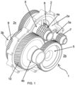
Figure 1 is a perspective view of a first embodiment of the gearbox according to the invention; -
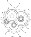
Figure 2 is a side view of the embodiment shown infigure 1 ; -
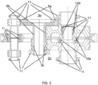
Figure 3 is a section view of the embodiment shown infigures 1 and2 along the section plane III - III offigure 2 ; -
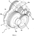
Figure 4 is a perspective view of a second embodiment of the gearbox according to the invention; -
Figure 5 is a side view of the embodiment shown infigure 4 ; -
Figure 6 is a section view of the embodiment shown infigure 4 along the section plane VI - VI offigure 5 ;
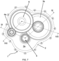
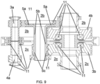
Figure 7 is a side view of a third embodiment of the gearbox according to the invention; -
Figure 8 is a section view of the embodiment shown infigure 7 along the section plane VIII - VIII offigure 7 ; -
Figure 9 is a section view of the embodiment shown infigure 7 along the section plane IX - IX offigure 7 ; and -
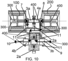
Figure 10 is a section view of a gearbox assembly according to the invention connected to two electric motors/engines and showing two torque flow paths originating from said motors/engines (such flow paths are represented by schematic arrows (300) and (400), these arrows not representing physical or material structural features of the invention). - In the annexed figures, the gearbox assembly according to the invention as a whole has been numbered with "1" and it basically comprises a frame (2), which is partially illustrated in the annexed figures (such frame (2) may also comprise external covers or shells, which are not depicted in the illustrations but which can be suitably shaped according to the engineering needs) and which defines a central plane (2a), both from the geometrical standpoint and from the physical mechanical standpoint: the central plane (2a) in turn defines a first and second half-spaces (2b; 2c) which lie in a respectively opposite fashion with respect to the central plane (2a) itself.
- According to various possible embodiments of the invention, the just cited central plane (2a) can just be ideally defined as a (geometric and non-material) separation surface/entity between the half-spaces (2b) and (2c), or it can be physically embodied by a material element, such as a plate-like element or body essentially resting in the middle of the frame (2) supporting the remaining elements of the gearbox (1) according to the present invention.
- Besides, it can be observed that according to the lexicon used for the illustration of the present invention the frame (2) can be considered as having various possible volumetric proportions and/or shapes, so as to properly accommodate and sustain/support the component of the driving lines herebelow cited and claimed and their relative ancillary sub-components, as it will be clarified later on in this description.
- Having in mind what just mentioned, the gearbox (1) also comprises a first and a second driving line which respectively comprise a first input torque element (3a) and a second torque input element (4a) - connectable to two respective torque sources such as electric motors - and a first output torque element (3b) and a second torque output element (4b) respectively placed at opposite ends of each driving line - connectable to wheels or axles of a vehicle.
- Advantageously, in the gearbox (1) according to the invention the first and/or the second driving line further comprise at least an intermediate element (5; 6) adapted to transmit torque coming from the first or from the second torque input elements (3a; 4a) towards the first or to the second torque output elements (3b; 4b) and across the just cited central plane (2a): otherwise stated, such an intermediate element (or, as in the embodiments shown in the annexed figures, the two intermediate elements (5; 6)) determine a "mechanical flow path" according to which the torque entering from/in a given half-space is transmitted along the driving line and, in correspondence of the cross-plane intermediate element, is "spatially shifted" in the opposite half-space.
- It is now to be observed that the "spatial shift" of the torque flow occurring along the two driving lines allows for an overall design wherein the transversal dimension of the structural components (with respect to the central plane (2a)) can be significantly reduced with respect to known-type gearboxes rated for the same torque handling capabilities: actually, this reduction in overall transversal occupancy is even more advantageously matched with the capability of dealing with torque sources lying in different "half-spaces", so that the overall assembly made by two engines and the gearbox (1) can be hosted in a reduced space within a vehicle (or also, in case of need, bigger and therefore more powerful motors can be hosted in the drivetrain-dedicated space thanks to the reduction of the gearbox cumbersomeness).
- As exemplificatively seen in the annexed figures, it can be seen that in the illustrated embodiments the mutual location of each driving line component is as follows:
- the first torque input element (3a), which is connectable to a first motor (100) (see for example
figure 10 ), lies in the first half-space (2b); - the first torque output element (3b) lies in the second half-space (2c);
- the second torque input element (4a), which is connectable to a second motor (200) (see, again,
figure 10 ), lies in the second half-space (2c); and - the second torque output element (4b) lies in the first half-space (2b).
- According to the invention, the intermediate element (5) is adapted to transfer a torque flow coming from the first torque input element (3a) towards the first torque output element (3b), while at the same time the intermediate element (6) is adapted to transfer a torque flow coming from the second torque input element (4a) towards the second torque output element (4b).
- Otherwise stated, the first and second torque input elements (3a; 4a) and their respective first and second torque output elements (3b; 4b), which from a "kinematic chain" standpoint can be regarded as being placed at opposite ends of each driving line, are lying in mutually opposite half-paces of the gearbox (1), and in this way it can be seen that the intermediate elements (5; 6) can be defined as being "cross-plane intermediate elements" without limiting the scope of the invention (yet with a substantial focus on their main function consisting in operating the "spatial shift" of the torque flow as hereabove cited).
- Delving deeper into details, it can be seen that the first and/or the second driving line further comprise a driving attachment (7; 8) which is (respectively) connected to the first or to the second torque input element (3a) or (4a) (such driving attachments (7; 8) are typically connectable to an engine, which in turn can be an electric engine), and a driven attachment (9; 10) which is connected to the first or to said second torque output elements (3b) or (4b) and which are typically connectable to an axle or to a wheel: this stated, it can be seen that the driving lines host the aforecited cross-plane intermediate elements (5; 6) which therefore are kinematically connected, in each driving line itself, to the respective driving attachment (7; 8) which is located at the beginning of each driving line and to the driven attachment (9; 10) which is located at the end of each driving line. According to the specific implementation of the components of each driving line (which are exemplificatively but not limitedly represented in the annexed drawings as "gears"), an overall transmission ratio for each driving line is defined, and such overall transmission ratio can be fixed (e.g. in a so-called single gear gearbox) or selectively modifiable: beside this, according to any possible operative requirements, the overall transmission ratios of the two driving lines can be identical/equal or can differ.
- As already been set into evidence, one or more of the driving attachments (7; 8) and/or the driven attachments (9; 10) and/or of the cross-plane intermediate elements (5; 6) can comprise toothed or crowned gears: such toothed or crowned gears are conveniently supported by respective shafts, and such shafts are rotationally supported along their respective axis by suitable housings (or, in possible exemplificative yet not limiting embodiments of the invention, by suitable portions of the frame (2)).
- According to a further aspect of the present invention, each of the first toothed or crowned gear (5a, 6a) also comprise an inner race supported by bearings: this structural option brings a further advantage consisting in the fact that the gearbox assembly can be furtherly made compact, since the bearing(unlike everywhere else in the gearbox where the bearing is next to gear) can be positioned underneath the gear itself.
- In order to achieve maximum mechanical efficiency in the driving lines, the shafts are placed within the frame (2) in a mutually parallel relationship and are transverse - e.g. perpendicular - to the central plane (2a); moreover, according to an aspect of the invention the shafts of the driving attachments (7; 8) or of the driven attachments (9; 10) can be lying on and rotating around a respective common (or "shared") geometrical axis in order to allow for a perfect alignment of the engines/motors and of the axles which are respectively connectable at the opposite ends/extremities of each driving line.
- With regard to the spatial location of the shafts and focusing on the cross-plane intermediate elements (5; 6), it can also be observed that the shafts for these components are mutually displaced (while keeping a mutual parallelism relationship) so that the ideal projection of the shafts of the driving attachments (7; 8), of the driven attachments (9; 10) and of the cross-plane intermediate elements (5; 6) on the central plane (2a) cooperatively define a so-called "L-shaped" (or "triangular") laying pattern in the frame (2): this particular geometric layout allows for compaction of the gearbox (1) not only in terms of width but also in terms of overall length.
- Looking closer at the cross-plane intermediate elements (5; 6), it can be seen that in the depicted embodiments they respectively comprise a first toothed or crowned gear (5a; 6a) residing in the first half-space (2b) or in the second half-spaces (2c), a cross-plane shaft (5b; 6b) protruding from the respective first toothed or crowned gear (5a; 6a) through the central plane (2a) and a second toothed or crowned gear (5c; 6c) residing in the second half-space (2c) or in the first half-space (2b) and supported by the just cited cross-plane shaft (5b; 6b): thanks to the cross-plane shaft, the torque flow coming from one half-space is driven into the other/opposite half-space, obtaining the main technical effect of the present invention as already described above.
- It should now be noted that according to the invention other kinematic devices may be used for defining the driving lines and/or its respective sub-components, such as belt drives, chain drives or whatever else is known to a skilled technician operating in the technical field of the invention itself: such alternative or functionally equivalent technical means can therefore be implemented without exceeding from the scope of the present invention.
- It is to be noted that according to the invention, the driving lines may comprise more than three gears, and in this case they can be defined as "gear trains" or "gear cascades": in these possible alternative embodiments of the invention, more than one cross-plane intermediate elements (5; 6) can be present in such gear trains/cascades, provided that at least in a given stage of such driving line the torque coming as an input in one half-space to be transferred as an output in the other opposite half-space defined by the frame (2) of the gearbox (1).
- Referring to the teaching just disclosed, it can therefore be seen that in case of a gear train/cascade wherein an even number (e.g. two, four, six or more) of cross-plane intermediate elements (5; 6) is present, the torque input coming from a given half-space is transferred as an output in the same half-space, while an odd number (e.g. one, three, five, seven or more) of cross-plane intermediate elements (5; 6) is present, the torque input coming from a given half-space is transferred as an output in the opposite half-space; all these possible embodiments are to be considered as falling within the present invention.
- In order to give the necessary support and minimization of friction losses, the gearbox (1) may further comprise a predetermined number of bearings (11) which are interposed between the frame (2) and the shafts of the driving attachments (7; 8) and/or of the driven attachments (9; 10) and/or of the cross-plane intermediate elements (5; 6): such bearings can conveniently be of any known type and can be arranged in suitable portions of the frame (2) and/or of the central plane (2a) according to the design requirements.
- The overall/resulting number and location of the bearings (11) can be suitably chosen in order to fulfill various technical requirements: for example, in a possible embodiment of the present invention at least one, and preferably all the cross-plane intermediate element/s (5, 6), is directly supported by at least one housing directly located in the frame (2): such housing is therefore not comprising bearings (11) located in the central plane (2a), and eventually suitably placed and dimensioned bearings (11) related to such cross-plane intermediate element/s (5; 6) can be resting in/on portions of the frame (2) not defining or belonging to the central plane (2a).
- Referring now to a further aspect of the present invention, and focusing in particular on the embodiment depicted in figures from 3 and 6, it can be seen that the shafts of the driving attachments (7; 8) and/or of the driven attachments (9; 10) are mutually facing each other in correspondence of the central plane (2a) of the frame (2), but in the embodiments depicted in figures from 1 to 6 the shafts of the driving attachments (7; 8) and/or of the driven attachments (9; 10) can be (at least partially) set into a mutual compenetration structural architecture: to this aims, the shafts may further comprise cross-plane protruding extremities (12a; 12b; 12c; 12d) which mutually compenetrate across the central plane (2a) of the frame (2).
- The benefits deriving from the mutual (and at least partial) compenetration of the shafts essentially consist in the fact that this geometric relationship helps in shortening the shafts themselves (and this results in an even more enhanced reduction of width for the whole gearbox (1)) and in the fact that such a mutual compenetration allows for a reciprocated self-centering effect which is directly acting on both shafts: this allows for a reduction of productive costs.
- It is to be observed that the cross-plane protruding extremities (12a; 12b; 12c; 12d) associated to the shafts of the driving attachments (7; 8) and/or of the driven attachments (9; 10) can be devised and implemented independently from the other features of the present invention, and it can also be observed that according to different possible embodiments of the invention, the driving attachments (7; 8) and/or of the driven attachments (9; 10) can be mutually compenetrating in various depths/lengths proportions according to design needs and taking into account the capability of withstanding a given amount of torque input (from the engines/motors) or whatever else can come into the calculations or into the operating conditions in terms of mechanical or thermal stresses.
- From an overall structural architecture standpoint, it can be observed that the protruding extremities (12a; 12b; 12c; 12d) essentially define a so-called "shaft-in-shaft" configuration or layout, wherein mutually opposite ends of the hereabove cited - and herebelow claimed - shafts are at least partially "nested" one within the other.
- The described, illustrated and claimed invention achieves the aforecited technical aims and surpasses the shortcomings of the prior art hereabove mentioned, starting but not being limited to the advantage consisting in a very high degree of volumetric compactness joined with the capability of dealing with an arbitrarily high amount of torque coming from at least two electric motors arranged in a so-called "side-by-side" architecture (that is, and according to the wording and the figures defining the lexicon of the present invention, an architecture wherein at least two motors are facing each other and are connected to a gearbox receiving torque inputs from opposite half-spaces).
- Besides, the overall structural architecture of the gearbox requires a limited overall number of bearings and allows for the settlement of a significative number of "shortened" shafts for the supporting of the crowned gears (and in particular, a shortening of the torque input and/or torque input shafts), and this once again leads to a rebate of production and assembling costs (which goes along with a high level of reliability, as well).
- Furthermore, the overall structure of the present invention can be implemented in various embodiments in order to cope with various ranges of torque outputs, maximum rotations per minute values and whatever else operating parameter which may characterize an electric motor or a couple of electric motors.
- Last but not least, the gearbox assembly according to the present invention can also be implemented in any other embodiment enclosed in its inventive concept as claimed, also by way of collateral modifications available to a skilled technician in the technical sector of pertinence of the invention itself, and thus maintaining the functional achievements of the invention along with practicality of production, usage, assembly and maintenance.
Claims (13)
- A gearbox for vehicles, comprising:- a frame (2) defining a central plane (2a) and a first half-space (2b) and a second half-space (2c) opposite to said first half-space (2b) with respect to said central plane (2a); and- a first and a second driving line supported by said frame (2) and respectively comprising a first and a second torque input element (3a; 4a) and a first and a second torque output element (3b; 4b),wherein the first and/or the second driving line further comprise at least an intermediate element (5; 6) adapted to transmit torque coming from the first or from the second torque input element (3a; 4a) towards the first or to the second torque output element (3b; 4b) and across the central plane (2a),characterized in that:- said central plane (2a) comprises a plate-like element belonging to the frame (2);- the first and/or of the second driving line comprises a driving attachment (7; 8) connected to said first or to said second torque input element (3a) or (4a) and preferably connectable to an engine, and more preferably connectable to an electric engine; and- the first and/or of the second driving line comprises a driven attachment (9; 10) connected to a first or to said second torque output elements (3b) or (4b) and preferably connectable to an axle or to a wheel; and- said cross-plane intermediate elements (5; 6) are kinematically connected to at least onf of said driving attachments (7; 8) and to at least one of the driven attachments (9; 10) in order to define a predetermined overall transmission ratio.
- A gearbox as in claim 1, wherein:- said first torque input element (3a) lying in the first half-space (2b);- said first torque output element (3b) lying in the second half-space (2c);- said second torque input element (4a) lying in the second half-space (2c); and- said second torque output element (4b) lying in the first half-space (2b), said intermediate element (5; 6) respectively being a cross-plane intermediate element transferring a torque flow coming from the first torque input element (3a) or coming from the second torque input element (4a) respectively towards the first torque output element (3b) or towards the second torque output element (4b).
- A gearbox as in claim 2, wherein the intermediate element (5) is adapted to transfer a torque flow coming from the first torque input element (3a) towards the first torque output element (3b), and wherein the intermediate element (6) is adapted to transfer a torque flow coming from the second torque input element (4a) towards the second torque output element (4b).
- A gearbox as in any one of the preceding claims, wherein one or more of said driving attachments (7; 8), of said driven attachments (9; 10) and of the cross-plane intermediate elements (5; 6) respectively comprise toothed or crowned gears, said toothed or crowned gears being supported by respective shafts, said shafts being rotationally supported along their respective axis by the frame (2) and/or by the central plane (2a).
- A gearbox as in claim 4, wherein said shafts are placed within the frame (2) in a mutually parallel relationship and are perpendicular to the central plane (2a), the shafts of the driving attachments (7; 8) or of the driven attachments (9; 10) lying on and rotating around a respective common geometrical axis.
- A gearbox as in claims 4 or 5, wherein the shafts of the cross-plane intermediate elements (5; 6) are mutually displaced so that projections of the shafts of the driving attachments (7; 8), of the driven attachments (9; 10) and of the cross-plane intermediate elements (5; 6) on the central plane (2a) cooperatively define an "L-shaped" laying pattern in the frame (2).
- A gearbox as in any one of the preceding claims, wherein at least one of the cross-plane intermediate elements (5; 6) comprises:- a first toothed or crowned gear (5a; 6a) residing in said first half-space (2b) or in said second half-spaces (2c);- a cross-plane shaft (5b; 6b) protruding from said first toothed or crowned gear (5a; 6a) through the central plane (2a); and- a second toothed or crowned gear (5c; 6c) residing in said second half-space (2c) or in said first half-space (2b) and supported by said cross-plane shaft (5b; 6b).
- A gearbox as in claim 7, wherein each of the first toothed or crowned gear (5a, 6a) also comprise an inner race supported by bearings.
- A gearbox as in any one of the preceding claims, wherein it further comprises a predetermined number of bearings (11) interposed between the frame (2) and/or the central plane (2a) and the shafts of the driving attachments (7; 8) and/or of the driven attachments (9; 10) and/or of the cross-plane intermediate elements (5; 6).
- A gearbox as in any one of the preceding claims, wherein the cross-plane intermediate element/s (5, 6), are directly supported by at least one housing directly located in the frame (2), said housing not comprising bearings (11) located in the central plane (2a).
- A gearbox as in claim 10, wherein said housing comprises bearings (11) on portions of the frame (2) not defining or belonging to said central plane (2a).
- A gearbox as in any one of the preceding claims, wherein the shafts of the driving attachments (7; 8) and/or of the driven attachments (9; 10) are mutually facing each other in correspondence of the central plane (2a) of the frame (2).
- A gearbox as in any one of the preceding claims, wherein the shafts of the driven attachments (7; 8) and/or of the driven attachments (9; 10) further comprise cross-plane protruding extremities (12a; 12b; 12c; 12d) which mutually compenetrate across the central plane (2a) of the frame (2), said protruding extremities defining a shaft-in-shaft configuration for the shafts of the driven attachments (7; 8) and/or of the driven attachments (9; 10).
Priority Applications (3)
| Application Number | Priority Date | Filing Date | Title |
|---|---|---|---|
| EP22194279.0A EP4336067B1 (en) | 2022-09-07 | 2022-09-07 | A gearbox/drivetrain for a vehicle |
| CN202311160617.5A CN117662724A (en) | 2022-09-07 | 2023-09-07 | Transmission system |
| US18/462,671 US12449019B2 (en) | 2022-09-07 | 2023-09-07 | Drivetrain |
Applications Claiming Priority (1)
| Application Number | Priority Date | Filing Date | Title |
|---|---|---|---|
| EP22194279.0A EP4336067B1 (en) | 2022-09-07 | 2022-09-07 | A gearbox/drivetrain for a vehicle |
Publications (2)
| Publication Number | Publication Date |
|---|---|
| EP4336067A1 EP4336067A1 (en) | 2024-03-13 |
| EP4336067B1 true EP4336067B1 (en) | 2025-05-21 |
Family
ID=83228560
Family Applications (1)
| Application Number | Title | Priority Date | Filing Date |
|---|---|---|---|
| EP22194279.0A Active EP4336067B1 (en) | 2022-09-07 | 2022-09-07 | A gearbox/drivetrain for a vehicle |
Country Status (3)
| Country | Link |
|---|---|
| US (1) | US12449019B2 (en) |
| EP (1) | EP4336067B1 (en) |
| CN (1) | CN117662724A (en) |
Family Cites Families (8)
| Publication number | Priority date | Publication date | Assignee | Title |
|---|---|---|---|---|
| US3168665A (en) * | 1962-01-02 | 1965-02-02 | Molon Motor & Coil Corp | Multiple rotor induction motor unit |
| BE1024269B1 (en) * | 2016-06-08 | 2018-01-15 | Punch Powertrain Nv | ELECTRIC DRIVE, TRANSMISSION, AND VEHICLE |
| US10228054B1 (en) * | 2017-05-22 | 2019-03-12 | Michael Wittig | Drive system for minimizing backlash |
| CN111655522B (en) * | 2017-12-15 | 2024-06-11 | 瑞维安知识产权控股有限责任公司 | Electric vehicle drive unit |
| JP7437377B2 (en) * | 2019-03-06 | 2024-02-22 | 三菱自動車工業株式会社 | Left and right wheel drive |
| US11787283B2 (en) * | 2020-03-31 | 2023-10-17 | Aisin Corporation | Vehicle drive apparatus and vehicle drive apparatus manufacturing method |
| US11635130B2 (en) * | 2020-06-04 | 2023-04-25 | Rivian Ip Holdings, Llc | Electric vehicle powertrain assembly having nested shafts |
| FR3131712B1 (en) * | 2022-01-08 | 2024-01-05 | Valeo Embrayages | PROPULSION SYSTEM FOR ELECTRIC VEHICLE |
-
2022
- 2022-09-07 EP EP22194279.0A patent/EP4336067B1/en active Active
-
2023
- 2023-09-07 CN CN202311160617.5A patent/CN117662724A/en active Pending
- 2023-09-07 US US18/462,671 patent/US12449019B2/en active Active
Also Published As
| Publication number | Publication date |
|---|---|
| US12449019B2 (en) | 2025-10-21 |
| US20240077132A1 (en) | 2024-03-07 |
| CN117662724A (en) | 2024-03-08 |
| EP4336067A1 (en) | 2024-03-13 |
Similar Documents
| Publication | Publication Date | Title |
|---|---|---|
| KR100221591B1 (en) | Auxiliary pump structure | |
| EP1326032A1 (en) | Series of motors with speed reducer | |
| CA1153908A (en) | Multiple countershaft simple transmission | |
| CN101251170A (en) | Multi-speed transmission with a countershaft gearing | |
| JP3051791B2 (en) | A series of transmissions with an internally meshing planetary gear structure | |
| CN113039083A (en) | Hybrid dual clutch transmission | |
| EP4635768A1 (en) | Hybrid power-driven system and vehicle | |
| CN115610210A (en) | An electric drive system for new energy vehicles | |
| US4679465A (en) | Eccentric swing gear transmission | |
| EP0659247B1 (en) | Motor vehicle gearbox | |
| EP4336067B1 (en) | A gearbox/drivetrain for a vehicle | |
| GB2071263A (en) | Twin screw extruder with power branching gearing | |
| KR102266498B1 (en) | Electric drive gearbox with a twin motor | |
| KR20010072677A (en) | Transmission with non-coaxial output | |
| EP2307747A1 (en) | Transmission gear engagement mechanism and method of operation | |
| RU2003112668A (en) | ELECTRIC DRIVE TO CREATE A TORQUE | |
| KR100221403B1 (en) | Transmission device of agricultural tractor | |
| EP0666969B1 (en) | A right-angle gear reduction unit | |
| JPH07269681A (en) | Rectangular-axes mechanical reduction gear | |
| KR102544720B1 (en) | load balancing device | |
| CN111299114B (en) | Synchronous transmission stepless amplitude modulation box of vibration equipment | |
| JP2004501325A (en) | Switching device for a transmission with two countershafts | |
| UA64369C2 (en) | Planetary reducer | |
| RU2062925C1 (en) | Two-flow gear transmission | |
| EP1803971A1 (en) | Ball transmission unit for a speed converter (variants) and a step-by-step gear box based thereon |
Legal Events
| Date | Code | Title | Description |
|---|---|---|---|
| PUAI | Public reference made under article 153(3) epc to a published international application that has entered the european phase |
Free format text: ORIGINAL CODE: 0009012 |
|
| STAA | Information on the status of an ep patent application or granted ep patent |
Free format text: STATUS: THE APPLICATION HAS BEEN PUBLISHED |
|
| AK | Designated contracting states |
Kind code of ref document: A1 Designated state(s): AL AT BE BG CH CY CZ DE DK EE ES FI FR GB GR HR HU IE IS IT LI LT LU LV MC MK MT NL NO PL PT RO RS SE SI SK SM TR |
|
| STAA | Information on the status of an ep patent application or granted ep patent |
Free format text: STATUS: REQUEST FOR EXAMINATION WAS MADE |
|
| 17P | Request for examination filed |
Effective date: 20240520 |
|
| RBV | Designated contracting states (corrected) |
Designated state(s): AL AT BE BG CH CY CZ DE DK EE ES FI FR GB GR HR HU IE IS IT LI LT LU LV MC MK MT NL NO PL PT RO RS SE SI SK SM TR |
|
| STAA | Information on the status of an ep patent application or granted ep patent |
Free format text: STATUS: EXAMINATION IS IN PROGRESS |
|
| 17Q | First examination report despatched |
Effective date: 20241114 |
|
| GRAP | Despatch of communication of intention to grant a patent |
Free format text: ORIGINAL CODE: EPIDOSNIGR1 |
|
| STAA | Information on the status of an ep patent application or granted ep patent |
Free format text: STATUS: GRANT OF PATENT IS INTENDED |
|
| INTG | Intention to grant announced |
Effective date: 20250225 |
|
| GRAS | Grant fee paid |
Free format text: ORIGINAL CODE: EPIDOSNIGR3 |
|
| GRAA | (expected) grant |
Free format text: ORIGINAL CODE: 0009210 |
|
| STAA | Information on the status of an ep patent application or granted ep patent |
Free format text: STATUS: THE PATENT HAS BEEN GRANTED |
|
| AK | Designated contracting states |
Kind code of ref document: B1 Designated state(s): AL AT BE BG CH CY CZ DE DK EE ES FI FR GB GR HR HU IE IS IT LI LT LU LV MC MK MT NL NO PL PT RO RS SE SI SK SM TR |
|
| REG | Reference to a national code |
Ref country code: GB Ref legal event code: FG4D |
|
| REG | Reference to a national code |
Ref country code: CH Ref legal event code: EP |
|
| REG | Reference to a national code |
Ref country code: DE Ref legal event code: R096 Ref document number: 602022014887 Country of ref document: DE |
|
| REG | Reference to a national code |
Ref country code: IE Ref legal event code: FG4D |
|
| P01 | Opt-out of the competence of the unified patent court (upc) registered |
Free format text: CASE NUMBER: APP_32385/2025 Effective date: 20250703 |
|
| REG | Reference to a national code |
Ref country code: NL Ref legal event code: MP Effective date: 20250521 |
|
| PG25 | Lapsed in a contracting state [announced via postgrant information from national office to epo] |
Ref country code: PT Free format text: LAPSE BECAUSE OF FAILURE TO SUBMIT A TRANSLATION OF THE DESCRIPTION OR TO PAY THE FEE WITHIN THE PRESCRIBED TIME-LIMIT Effective date: 20250922 Ref country code: FI Free format text: LAPSE BECAUSE OF FAILURE TO SUBMIT A TRANSLATION OF THE DESCRIPTION OR TO PAY THE FEE WITHIN THE PRESCRIBED TIME-LIMIT Effective date: 20250521 Ref country code: ES Free format text: LAPSE BECAUSE OF FAILURE TO SUBMIT A TRANSLATION OF THE DESCRIPTION OR TO PAY THE FEE WITHIN THE PRESCRIBED TIME-LIMIT Effective date: 20250521 |
|
| REG | Reference to a national code |
Ref country code: LT Ref legal event code: MG9D |
|
| PG25 | Lapsed in a contracting state [announced via postgrant information from national office to epo] |
Ref country code: NO Free format text: LAPSE BECAUSE OF FAILURE TO SUBMIT A TRANSLATION OF THE DESCRIPTION OR TO PAY THE FEE WITHIN THE PRESCRIBED TIME-LIMIT Effective date: 20250821 Ref country code: GR Free format text: LAPSE BECAUSE OF FAILURE TO SUBMIT A TRANSLATION OF THE DESCRIPTION OR TO PAY THE FEE WITHIN THE PRESCRIBED TIME-LIMIT Effective date: 20250822 |
|
| PG25 | Lapsed in a contracting state [announced via postgrant information from national office to epo] |
Ref country code: NL Free format text: LAPSE BECAUSE OF FAILURE TO SUBMIT A TRANSLATION OF THE DESCRIPTION OR TO PAY THE FEE WITHIN THE PRESCRIBED TIME-LIMIT Effective date: 20250521 Ref country code: PL Free format text: LAPSE BECAUSE OF FAILURE TO SUBMIT A TRANSLATION OF THE DESCRIPTION OR TO PAY THE FEE WITHIN THE PRESCRIBED TIME-LIMIT Effective date: 20250521 |
|
| PG25 | Lapsed in a contracting state [announced via postgrant information from national office to epo] |
Ref country code: BG Free format text: LAPSE BECAUSE OF FAILURE TO SUBMIT A TRANSLATION OF THE DESCRIPTION OR TO PAY THE FEE WITHIN THE PRESCRIBED TIME-LIMIT Effective date: 20250521 |
|
| PG25 | Lapsed in a contracting state [announced via postgrant information from national office to epo] |
Ref country code: HR Free format text: LAPSE BECAUSE OF FAILURE TO SUBMIT A TRANSLATION OF THE DESCRIPTION OR TO PAY THE FEE WITHIN THE PRESCRIBED TIME-LIMIT Effective date: 20250521 |
|
| PGFP | Annual fee paid to national office [announced via postgrant information from national office to epo] |
Ref country code: FR Payment date: 20250930 Year of fee payment: 4 |
|
| PG25 | Lapsed in a contracting state [announced via postgrant information from national office to epo] |
Ref country code: RS Free format text: LAPSE BECAUSE OF FAILURE TO SUBMIT A TRANSLATION OF THE DESCRIPTION OR TO PAY THE FEE WITHIN THE PRESCRIBED TIME-LIMIT Effective date: 20250821 |
|
| PG25 | Lapsed in a contracting state [announced via postgrant information from national office to epo] |
Ref country code: IS Free format text: LAPSE BECAUSE OF FAILURE TO SUBMIT A TRANSLATION OF THE DESCRIPTION OR TO PAY THE FEE WITHIN THE PRESCRIBED TIME-LIMIT Effective date: 20250921 |
|
| PG25 | Lapsed in a contracting state [announced via postgrant information from national office to epo] |
Ref country code: LV Free format text: LAPSE BECAUSE OF FAILURE TO SUBMIT A TRANSLATION OF THE DESCRIPTION OR TO PAY THE FEE WITHIN THE PRESCRIBED TIME-LIMIT Effective date: 20250521 |
|
| REG | Reference to a national code |
Ref country code: AT Ref legal event code: MK05 Ref document number: 1796974 Country of ref document: AT Kind code of ref document: T Effective date: 20250521 |
|
| PGFP | Annual fee paid to national office [announced via postgrant information from national office to epo] |
Ref country code: DE Payment date: 20250930 Year of fee payment: 4 |
|
| PG25 | Lapsed in a contracting state [announced via postgrant information from national office to epo] |
Ref country code: DK Free format text: LAPSE BECAUSE OF FAILURE TO SUBMIT A TRANSLATION OF THE DESCRIPTION OR TO PAY THE FEE WITHIN THE PRESCRIBED TIME-LIMIT Effective date: 20250521 Ref country code: SM Free format text: LAPSE BECAUSE OF FAILURE TO SUBMIT A TRANSLATION OF THE DESCRIPTION OR TO PAY THE FEE WITHIN THE PRESCRIBED TIME-LIMIT Effective date: 20250521 Ref country code: AT Free format text: LAPSE BECAUSE OF FAILURE TO SUBMIT A TRANSLATION OF THE DESCRIPTION OR TO PAY THE FEE WITHIN THE PRESCRIBED TIME-LIMIT Effective date: 20250521 |
|
| PGFP | Annual fee paid to national office [announced via postgrant information from national office to epo] |
Ref country code: IT Payment date: 20250930 Year of fee payment: 4 |
|
| PG25 | Lapsed in a contracting state [announced via postgrant information from national office to epo] |
Ref country code: CZ Free format text: LAPSE BECAUSE OF FAILURE TO SUBMIT A TRANSLATION OF THE DESCRIPTION OR TO PAY THE FEE WITHIN THE PRESCRIBED TIME-LIMIT Effective date: 20250521 |
|
| PG25 | Lapsed in a contracting state [announced via postgrant information from national office to epo] |
Ref country code: EE Free format text: LAPSE BECAUSE OF FAILURE TO SUBMIT A TRANSLATION OF THE DESCRIPTION OR TO PAY THE FEE WITHIN THE PRESCRIBED TIME-LIMIT Effective date: 20250521 |
|
| PG25 | Lapsed in a contracting state [announced via postgrant information from national office to epo] |
Ref country code: SK Free format text: LAPSE BECAUSE OF FAILURE TO SUBMIT A TRANSLATION OF THE DESCRIPTION OR TO PAY THE FEE WITHIN THE PRESCRIBED TIME-LIMIT Effective date: 20250521 |
|
| REG | Reference to a national code |
Ref country code: DE Ref legal event code: R097 Ref document number: 602022014887 Country of ref document: DE |
|
| PG25 | Lapsed in a contracting state [announced via postgrant information from national office to epo] |
Ref country code: RO Free format text: LAPSE BECAUSE OF FAILURE TO SUBMIT A TRANSLATION OF THE DESCRIPTION OR TO PAY THE FEE WITHIN THE PRESCRIBED TIME-LIMIT Effective date: 20250521 |
|
| PLBE | No opposition filed within time limit |
Free format text: ORIGINAL CODE: 0009261 |
|
| STAA | Information on the status of an ep patent application or granted ep patent |
Free format text: STATUS: NO OPPOSITION FILED WITHIN TIME LIMIT |
|
| REG | Reference to a national code |
Ref country code: CH Ref legal event code: L10 Free format text: ST27 STATUS EVENT CODE: U-0-0-L10-L00 (AS PROVIDED BY THE NATIONAL OFFICE) Effective date: 20260402 |