EP4335752A1 - Steuerung einer unbemannten vorrichtung - Google Patents
Steuerung einer unbemannten vorrichtung Download PDFInfo
- Publication number
- EP4335752A1 EP4335752A1 EP22871364.0A EP22871364A EP4335752A1 EP 4335752 A1 EP4335752 A1 EP 4335752A1 EP 22871364 A EP22871364 A EP 22871364A EP 4335752 A1 EP4335752 A1 EP 4335752A1
- Authority
- EP
- European Patent Office
- Prior art keywords
- rotation speed
- target
- target rotation
- unmanned device
- threshold
- Prior art date
- Legal status (The legal status is an assumption and is not a legal conclusion. Google has not performed a legal analysis and makes no representation as to the accuracy of the status listed.)
- Pending
Links
- 238000000034 method Methods 0.000 claims abstract description 64
- 238000004590 computer program Methods 0.000 claims description 20
- 230000001133 acceleration Effects 0.000 claims description 6
- 230000004044 response Effects 0.000 claims 3
- 238000010586 diagram Methods 0.000 description 10
- 230000006870 function Effects 0.000 description 10
- 230000006872 improvement Effects 0.000 description 9
- 238000005516 engineering process Methods 0.000 description 7
- 238000012545 processing Methods 0.000 description 7
- 230000009466 transformation Effects 0.000 description 6
- 230000008569 process Effects 0.000 description 5
- 230000007423 decrease Effects 0.000 description 3
- 230000003247 decreasing effect Effects 0.000 description 3
- 230000003287 optical effect Effects 0.000 description 3
- 102000015779 HDL Lipoproteins Human genes 0.000 description 2
- 108010010234 HDL Lipoproteins Proteins 0.000 description 2
- 230000008859 change Effects 0.000 description 2
- 238000011161 development Methods 0.000 description 2
- 230000007613 environmental effect Effects 0.000 description 2
- 230000004048 modification Effects 0.000 description 2
- 238000012986 modification Methods 0.000 description 2
- 230000009286 beneficial effect Effects 0.000 description 1
- 230000005540 biological transmission Effects 0.000 description 1
- 230000001413 cellular effect Effects 0.000 description 1
- 239000003245 coal Substances 0.000 description 1
- 238000004891 communication Methods 0.000 description 1
- 238000013461 design Methods 0.000 description 1
- 230000002085 persistent effect Effects 0.000 description 1
- 229920001296 polysiloxane Polymers 0.000 description 1
- 230000000750 progressive effect Effects 0.000 description 1
- 239000010979 ruby Substances 0.000 description 1
- 229910001750 ruby Inorganic materials 0.000 description 1
- 230000003068 static effect Effects 0.000 description 1
- 230000002747 voluntary effect Effects 0.000 description 1
Images

Classifications
-
- B—PERFORMING OPERATIONS; TRANSPORTING
- B64—AIRCRAFT; AVIATION; COSMONAUTICS
- B64D—EQUIPMENT FOR FITTING IN OR TO AIRCRAFT; FLIGHT SUITS; PARACHUTES; ARRANGEMENT OR MOUNTING OF POWER PLANTS OR PROPULSION TRANSMISSIONS IN AIRCRAFT
- B64D31/00—Power plant control systems; Arrangement of power plant control systems in aircraft
- B64D31/02—Initiating means
- B64D31/06—Initiating means actuated automatically
-
- B—PERFORMING OPERATIONS; TRANSPORTING
- B64—AIRCRAFT; AVIATION; COSMONAUTICS
- B64C—AEROPLANES; HELICOPTERS
- B64C39/00—Aircraft not otherwise provided for
- B64C39/02—Aircraft not otherwise provided for characterised by special use
- B64C39/024—Aircraft not otherwise provided for characterised by special use of the remote controlled vehicle type, i.e. RPV
-
- B—PERFORMING OPERATIONS; TRANSPORTING
- B64—AIRCRAFT; AVIATION; COSMONAUTICS
- B64D—EQUIPMENT FOR FITTING IN OR TO AIRCRAFT; FLIGHT SUITS; PARACHUTES; ARRANGEMENT OR MOUNTING OF POWER PLANTS OR PROPULSION TRANSMISSIONS IN AIRCRAFT
- B64D27/00—Arrangement or mounting of power plants in aircraft; Aircraft characterised by the type or position of power plants
- B64D27/02—Aircraft characterised by the type or position of power plants
- B64D27/24—Aircraft characterised by the type or position of power plants using steam or spring force
-
- B—PERFORMING OPERATIONS; TRANSPORTING
- B60—VEHICLES IN GENERAL
- B60L—PROPULSION OF ELECTRICALLY-PROPELLED VEHICLES; SUPPLYING ELECTRIC POWER FOR AUXILIARY EQUIPMENT OF ELECTRICALLY-PROPELLED VEHICLES; ELECTRODYNAMIC BRAKE SYSTEMS FOR VEHICLES IN GENERAL; MAGNETIC SUSPENSION OR LEVITATION FOR VEHICLES; MONITORING OPERATING VARIABLES OF ELECTRICALLY-PROPELLED VEHICLES; ELECTRIC SAFETY DEVICES FOR ELECTRICALLY-PROPELLED VEHICLES
- B60L2200/00—Type of vehicles
- B60L2200/10—Air crafts
-
- B—PERFORMING OPERATIONS; TRANSPORTING
- B64—AIRCRAFT; AVIATION; COSMONAUTICS
- B64U—UNMANNED AERIAL VEHICLES [UAV]; EQUIPMENT THEREFOR
- B64U50/00—Propulsion; Power supply
- B64U50/10—Propulsion
- B64U50/19—Propulsion using electrically powered motors
-
- Y—GENERAL TAGGING OF NEW TECHNOLOGICAL DEVELOPMENTS; GENERAL TAGGING OF CROSS-SECTIONAL TECHNOLOGIES SPANNING OVER SEVERAL SECTIONS OF THE IPC; TECHNICAL SUBJECTS COVERED BY FORMER USPC CROSS-REFERENCE ART COLLECTIONS [XRACs] AND DIGESTS
- Y02—TECHNOLOGIES OR APPLICATIONS FOR MITIGATION OR ADAPTATION AGAINST CLIMATE CHANGE
- Y02T—CLIMATE CHANGE MITIGATION TECHNOLOGIES RELATED TO TRANSPORTATION
- Y02T50/00—Aeronautics or air transport
- Y02T50/60—Efficient propulsion technologies, e.g. for aircraft
Definitions
- the present disclosure relates to the field of unmanned driving technologies, and in particular, to an unmanned device control method and apparatus, a storage medium, and an electronic device.
- an electric unmanned device driven by electric power gradually becomes popular.
- a main power source of the electric unmanned device is a power battery mounted in the electric unmanned device.
- an electric unmanned aerial vehicle Using an electric unmanned aerial vehicle as an example, a power battery is mounted in the electric unmanned aerial vehicle. In a flight process of the electric unmanned aerial vehicle, through a voltage inputted by the power battery to the unmanned aerial vehicle, each motor in the electric unmanned aerial vehicle can obtain power to cause the unmanned aerial vehicle to rotate, and the electric unmanned aerial vehicle obtains power required for flying through rotation of each motor.
- the present disclosure provides an unmanned device control method, including: determining, according to state information and/or environment information of an unmanned device, thrust force required for the unmanned device and a target rotation speed required for a motor of the unmanned device to provide the thrust force; determining whether a difference between the target rotation speed and a rotation speed threshold corresponding to a first voltage is less than a first threshold; and adjusting, if the difference is less than the first threshold, the first voltage inputted into the motor of the unmanned device according to the target rotation speed to obtain a target voltage, and controlling the unmanned device by using the target voltage.
- the rotation speed threshold includes a rotation speed upper limit threshold and a rotation speed lower limit threshold.
- the state information of the unmanned device includes: at least one of a weight, an acceleration, or a speed of the unmanned device.
- the determining, according to state information and/or environment information of an unmanned device, thrust force required for the unmanned device includes: determining a target state that the unmanned device needs to reach at a specified moment; and determining the thrust force required for the unmanned device according to the state information, the environment information, and the target state of the unmanned device at a current moment.
- the adjusting the first voltage inputted into the motor of the unmanned device according to the target rotation speed to obtain a target voltage, and controlling the unmanned device by using the target voltage includes: determining, according to the target rotation speed, a target rotation speed threshold corresponding to the target rotation speed; determining, according to the target rotation speed threshold, the target voltage corresponding to the target rotation speed threshold; and adjusting the first voltage inputted into the motor of the unmanned device according to the target voltage.
- a difference between the target rotation speed and a rotation speed threshold corresponding to the target voltage is not less than a second threshold.
- the determining a target rotation speed threshold corresponding to the target rotation speed includes: determining a target rotation speed upper limit threshold and a target rotation speed lower limit threshold corresponding to the target rotation speed; and the determining, according to the target rotation speed threshold, the target voltage corresponding to the target rotation speed threshold includes: determining, according to the target rotation speed upper limit threshold and the target rotation speed lower limit threshold, a target rotation speed range from the target rotation speed lower limit threshold to the target rotation speed upper limit threshold; and determining, according to the target rotation speed range, the target voltage corresponding to the target rotation speed range.
- the present disclosure provides an unmanned device control apparatus, including: a target voltage determining module, configured to determine, according to state information and/or environment information of an unmanned device, thrust force required for the unmanned device and a target rotation speed required for a motor of the unmanned device to provide the thrust force; and a voltage adjustment module, configured to: determine whether a difference between the target rotation speed and a rotation speed threshold corresponding to a first voltage is less than a first threshold; and adjust, if the difference is less than the first threshold, the first voltage inputted into the motor of the unmanned device according to the target rotation speed to obtain a target voltage, and control the unmanned device by using the target voltage.
- a target voltage determining module configured to determine, according to state information and/or environment information of an unmanned device, thrust force required for the unmanned device and a target rotation speed required for a motor of the unmanned device to provide the thrust force
- a voltage adjustment module configured to: determine whether a difference between the target rotation speed and a rotation speed threshold corresponding to a first voltage is
- the present disclosure provides a computer-readable storage medium, storing a computer program, where when the computer program is executed by a processor, the foregoing unmanned device control method is implemented.
- the present disclosure provides an unmanned device, including a memory, a processor, and a computer program stored in the memory and executable on the processor, where when executing the program, the processor implements the foregoing unmanned device control method.
- thrust force required for an unmanned device and a target rotation speed required for a motor of the unmanned device to provide the thrust force are determined according to state information and/or environment information of the unmanned device, a voltage inputted into the motor of the unmanned device is adjusted according to the target rotation speed, and the unmanned device is controlled by using an adjusted voltage.
- An unmanned device obtains power from rotation of a motor mounted in the unmanned device, and a power source of rotation of the motor is a voltage outputted by a power battery mounted on the unmanned device.
- a rotation speed of the motor may be increased or decreased, so that the unmanned device can still operate normally.
- the rotation speed of the motor is excessively close to a rotation speed upper limit or lower limit corresponding to a current voltage, although the rotation speed still falls within a range corresponding to the rotation speed upper limit or lower limit, a problem of power saturation may occur.
- the control performance of an electric unmanned aerial vehicle is decreased, and the electric unmanned aerial vehicle may even be out of control and cannot fly according to a preset target state.
- the rotation speed of each motor of the electric unmanned aerial vehicle may be increased, so that the electric unmanned aerial vehicle can obtain sufficient thrust force.
- the rotation speed of each motor of the electric unmanned aerial vehicle may be decreased, so that thrust force to the electric unmanned aerial vehicle is reduced.
- the rotation speed of each motor is excessively high or excessively low, the problem of power saturation of the electric unmanned aerial vehicle may occur. Therefore, how to avoid power saturation when controlling the unmanned device to execute tasks is a problem that needs to be resolved urgently.
- FIG. 1 is a schematic flowchart of an unmanned device control method according to an embodiment of the present disclosure, and includes step S100 to step S104.
- Thrust force required for the unmanned device and a target rotation speed required for a motor of the unmanned device to provide the thrust force are determined according to state information and/or environment information of an unmanned device,.
- the unmanned device control method provided in the present disclosure may be performed by an unmanned device or may be performed by an electronic device that can control the unmanned device, for example, a notebook computer, a mobile phone, a service, or the like, which is not limited in the present disclosure.
- a notebook computer for example, a notebook computer, a mobile phone, a service, or the like
- the following is described by merely using an example in which an execution entity is an unmanned device.
- the unmanned device mentioned in the present disclosure may include a device that can implement self-driving such as an unmanned aerial vehicle, an unmanned vehicle, a robot, or an automatic delivery device.
- the unmanned device to which the unmanned device control method provided in the present disclosure is applied may be configured to execute a delivery task in the delivery field, for example, a delivery service scenario in which the unmanned device is used to perform express delivery, logistics distribution, or take-out delivery.
- a delivery service scenario in which the unmanned device is used to perform express delivery, logistics distribution, or take-out delivery.
- the following is described by merely using an example in which the unmanned device is an unmanned aerial vehicle.
- an unmanned driving system in the unmanned aerial vehicle may plan, according to received task information sent by a server, a target route for the unmanned aerial vehicle to execute a task.
- the unmanned aerial vehicle may fly according to the pre-planned target route. That is, every moment the unmanned aerial vehicle needs to reach a pre-planned target state.
- the unmanned aerial vehicle may monitor state information of the unmanned aerial vehicle and surrounding environment information in real time, to ensure the safety of the unmanned aerial vehicle during task execution.
- the state information includes: at least one of a weight, a speed, or an acceleration of the unmanned aerial vehicle, where the weight of the unmanned aerial vehicle may include the weight of the unmanned aerial vehicle or may alternatively include a weight loaded by the unmanned aerial vehicle.
- the weight of the unmanned aerial vehicle may include the weight of the unmanned aerial vehicle or may alternatively include a weight loaded by the unmanned aerial vehicle.
- the unmanned aerial vehicle executes a logistics distribution task, after the unmanned aerial vehicle loads products that need to be delivered, the weight of the unmanned aerial vehicle may be increased, and the motor of the unmanned aerial vehicle needs to increase the rotation speed to enable the unmanned aerial vehicle to fly in the target state.
- the rotation speed of the motor of the unmanned aerial vehicle may reach a rotation speed upper limit threshold, and the unmanned aerial vehicle may encounter the problem of power saturation.
- the unmanned aerial vehicle may decrease the rotation speed, so that the unmanned aerial vehicle can still fly in the target state.
- the rotation speed of the motor of the unmanned aerial vehicle may reach a rotation speed lower limit threshold, and the unmanned aerial vehicle may also encounter the problem of power saturation.
- the target state includes: at least one of the speed or the acceleration of the unmanned aerial vehicle.
- the environment information monitored by the unmanned aerial vehicle includes a wind speed, and may further include other environmental conditions such as rainfall, which is not limited in the present disclosure.
- the environment information may further include a traveling slope of the unmanned vehicle.
- the unmanned aerial vehicle may determine resistance encountered by the unmanned aerial vehicle according to an environment at a current moment, and then determine, according to a difference between an actual state and the target state at the current moment of the unmanned aerial vehicle, thrust force required for enabling the unmanned aerial vehicle to reach the target state at a specified moment.
- the specified moment may be the current moment or may be another moment, which is not limited in the present disclosure.
- the power of the unmanned aerial vehicle during flight is from the rotation of the motor, a higher rotation speed of the motor indicates greater thrust force that the unmanned aerial vehicle can obtain, and conversely, a lower rotation speed of the motor indicates smaller thrust force that the unmanned aerial vehicle can obtain. Therefore, according to the required thrust force, the unmanned aerial vehicle may determine the target rotation speed required for the motor to provide the thrust force.
- the unmanned aerial vehicle needs to fly from a place A to a place C at a speed of 10 m/s, and when a voltage inputted to the motor of the unmanned aerial vehicle is 4 V and the rotation speed of the motor of the unmanned aerial vehicle is 1500 rpm, the unmanned aerial vehicle can fly according to the speed of 10 m/s.
- a motor rotation speed corresponding to the voltage 4 V ranges from 1000 rpm to 2000 rpm, and the unmanned aerial vehicle may not encounter the problem of power saturation.
- the unmanned aerial vehicle monitors an actual state of the unmanned aerial vehicle and environmental conditions such as a wind speed of a position at which the unmanned aerial vehicle is located.
- the unmanned aerial vehicle may determine, according to a monitored wind speed, the actual state at the current moment, and the target state that the unmanned aerial vehicle needs to reach, that the required thrust force of the unmanned aerial vehicle at the current moment is 20 N, and may determine, according to that the required thrust force of the unmanned aerial vehicle at the current moment is 20 N, that the target rotation speed required for the motor of the unmanned aerial vehicle to provide the thrust force 20 N is 1900 rpm.
- S 102 Whether a difference between the target rotation speed and a rotation speed threshold corresponding to a first voltage being less than a first threshold is determined, and if yes, S 104 is performed.
- the unmanned driving system in the unmanned aerial vehicle may determine whether the difference between the target rotation speed determined in step S 100 and the rotation speed threshold corresponding to the first voltage is less than the first threshold, to determine whether the first voltage inputted into the motor of the unmanned device needs to be adjusted. For example, the unmanned driving system determines whether a value obtained by subtracting a rotation speed lower limit threshold corresponding to the first voltage inputted into the motor of the unmanned aerial vehicle from the target rotation speed is less than the first threshold, or determines whether a value obtained by subtracting the target rotation speed from a rotation speed upper limit threshold corresponding to the first voltage inputted into the motor of the unmanned aerial vehicle is less than the first threshold.
- the first voltage may be a voltage inputted into the motor of the unmanned device at the current moment, which is not limited in the present disclosure.
- the rotation speed threshold includes a rotation speed upper limit threshold and a rotation speed lower limit threshold.
- S104 The first voltage inputted into the motor of the unmanned device according to the target rotation speed is adjusted to obtain a target voltage, and control the unmanned device by using the target voltage.
- step S100 it may be learned from step S100 that, when the rotation speed of the motor of the unmanned aerial vehicle is close to the rotation speed threshold corresponding to the first voltage (the voltage at the current moment), the unmanned aerial vehicle generally may encounter the problem of power saturation.
- a target rotation speed upper limit threshold and a target rotation speed lower limit threshold whose differences with the target rotation speed are not less than a second threshold may be determined, a corresponding rotation speed range from the rotation speed lower limit threshold to the rotation speed upper limit threshold is further determined, and the determined rotation speed range is used as a target rotation speed range.
- the rotation speed of the motor is also related to the voltage inputted into the motor.
- a highest rotation speed and a lowest rotation speed of the motor of the unmanned aerial vehicle are different under different voltages, and as the voltage increases or decreases, the highest rotation speed and the lowest rotation speed of the motor also increase or decrease.
- the unmanned device may determine, according to a target rotation speed threshold, a target voltage corresponding to the target rotation speed threshold.
- the range from the target rotation speed lower limit threshold to the target rotation speed upper limit threshold is the target rotation speed range, and each rotation speed range corresponds to one target voltage, so that a target rotation speed lower limit threshold and a target rotation speed upper limit threshold corresponding to a same target rotation speed correspond to a same target voltage.
- a rotation speed threshold to the target voltage includes a target rotation speed upper limit threshold and a target rotation speed lower limit threshold, and it may be learned from the foregoing description that, a difference between the target rotation speed and the rotation speed threshold corresponding to the target voltage (the target rotation speed upper limit threshold and the target rotation speed lower limit threshold) is not less than the second threshold.
- a transformation module that can adjust the voltage inputted into the motor is mounted between the power battery and each motor of the unmanned aerial vehicle. After determining the target voltage inputted into the motor according to the foregoing method, the unmanned aerial vehicle adjusts the first voltage (the actual voltage at the current moment) to the target voltage through the transformation module, so that the motor can reach the target rotation speed under an adjusted voltage (the target voltage), and the problem of power saturation may not occur.
- the unmanned aerial vehicle may determine, according to the target rotation speed 1900 rpm, a target rotation speed lower limit threshold 1400 rpm and a target rotation speed upper limit threshold 2400 rpm whose differences with the target rotation speed is not less 500 rpm, so that a target rotation speed range from 1400 rpm to 2400 rpm may be determined.
- the unmanned aerial vehicle may determine that a target voltage corresponding to the target rotation speed range from 1400 rpm to 2400 rpm is 4.8 V.
- the transformation module mounted in the unmanned aerial vehicle adjusts the voltage 4 V inputted into the motor to 4.8 V. After the voltage inputted into the unmanned aerial vehicle is adjusted to 4.8 V, when the motor of the unmanned aerial vehicle reaches the target rotation speed 1900 rpm, at the current moment, the rotation speed lower limit threshold is 1400 rpm, the rotation speed upper limit threshold is 2400 rpm, and the differences between the rotation speed of the motor of the unmanned aerial vehicle and the rotation speed upper limit threshold and the rotation speed lower limit threshold at the current moment are both not less than 500 rpm, so that the unmanned aerial vehicle can still fly at the speed of 10 m/s in the environment of being against the wind at the current moment, and the problem of power saturation may not occur.
- the unmanned aerial vehicle When the absolute value of the difference between the target rotation speed and the rotation speed threshold at the current moment is not less than the first threshold, it indicates that the unmanned aerial vehicle currently may not encounter the problem of power saturation, and therefore, the voltage inputted into the motor of the unmanned aerial vehicle does not need to be adjusted.
- the unmanned aerial vehicle may continue to use an actual voltage at the current moment to control the unmanned aerial vehicle.
- the unmanned aerial vehicle may also use this method to adjust the voltage inputted into the motor.
- the unmanned aerial vehicle may determine an actual rotation speed range corresponding to the first voltage (the actual voltage inputted into the motor at the current moment), and adjust, when determining that the target rotation speed is not within the actual rotation speed range, the voltage inputted into the motor according to the target rotation speed, where the actual rotation speed range includes the rotation speed upper limit threshold and the rotation speed lower limit threshold corresponding to the actual voltage inputted into the motor.
- the unmanned aerial vehicle when the target rotation speed of the unmanned aerial vehicle reaches or is close to the rotation speed upper limit threshold corresponding to the voltage inputted into the motor at the current moment, the unmanned aerial vehicle encounters the problem of power saturation, and when the target rotation speed of the unmanned aerial vehicle reaches or is close to the rotation speed lower limit threshold corresponding to the first voltage (the voltage inputted into the motor at the current moment), the unmanned aerial vehicle also encounters the problem of power saturation, so that the unmanned aerial vehicle may adjust the voltage inputted into the motor by using step S 100 to step S 104, to prevent the unmanned aerial vehicle from encountering the problem of power saturation.
- a power module mounted on the unmanned aerial vehicle may send a rotation speed instruction to the motor, and after receiving the rotation speed instruction sent by the power module, the motor may adjust the rotation speed of the motor to a specified rotation speed corresponding to the rotation speed instruction.
- the rotation speed instruction includes a specified rotation speed ratio used for causing the motor of the unmanned aerial vehicle to operate according to a rotation speed corresponding to the specified rotation speed ratio, where the specified rotation speed ratio is a ratio of a corresponding rotation speed range from a rotation speed lower limit threshold to a rotation speed upper limit threshold under the current voltage.
- the motor of the unmanned aerial vehicle may determine, according to the specified rotation speed ratio in the received rotation speed instruction and the rotation speed range corresponding to the current voltage, the specified rotation speed corresponding to the specified rotation speed ratio, and operate according to the determined specified rotation speed. For example, when the specified rotation speed ratio in the rotation speed instruction is 0%, a corresponding rotation speed is the rotation speed lower limit threshold under the current voltage, and when the specified rotation speed ratio in the rotation speed instruction is 100%, a corresponding rotation speed is the rotation speed upper limit threshold under the current voltage.
- a rotation speed instruction whose specified rotation speed ratio is 50% is generally used to control the rotation speed of the motor.
- the transformation module of the unmanned aerial vehicle may determine the target rotation speed threshold according to the rotation speed instruction at the current moment and the target rotation speed, and then determine the target voltage corresponding to the target rotation speed threshold according to the determined target rotation speed threshold. In this way, the unmanned aerial vehicle only needs to change the voltage to enable the rotation speed of the motor of the unmanned aerial vehicle to remain within an ideal range in any time, and the unmanned aerial vehicle may be prevented from encountering the problem of power saturation.
- the unmanned aerial vehicle determines that the target rotation speed is 1750 rpm through step S100, and the transformation module of the unmanned aerial vehicle determines that the target rotation speed range is from 1500 rpm to 2000 rpm according to the rotation speed instruction whose specified rotation speed ratio is 50% and the target rotation speed 1750 rpm.
- the transformation module may determine that the target voltage corresponding to the target rotation speed range from 1500 rpm to 2000 rpm is 4.7 V, and adjust the voltage outputted by the power battery to the target voltage 4.7 V and input the adjusted voltage to the motor.
- the unmanned aerial vehicle can use this method
- another unmanned device may also use this method, for example, an unmanned vehicle, where the unmanned aerial vehicle operates depending on the power battery mounted on the unmanned aerial vehicle.
- the present disclosure further provides a corresponding unmanned device control apparatus, as shown in FIG. 2 .
- FIG. 2 is a schematic diagram of an unmanned device control apparatus according to the present disclosure.
- the unmanned device control apparatus includes: a target voltage determining module 201 and a voltage adjustment module 202.
- the target voltage determining module 201 is configured to determine, according to state information and/or environment information of an unmanned device, thrust force required for the unmanned device and a target rotation speed required for a motor of the unmanned device to provide the thrust force;
- the voltage adjustment module 202 is configured to: determine whether a difference between the target rotation speed and a rotation speed threshold corresponding to a first voltage is less than a first threshold; and adjust, if the difference is less than the first threshold, the first voltage inputted into the motor of the unmanned device according to the target rotation speed to obtain a target voltage, and control the unmanned device by using the target voltage.
- the rotation speed threshold includes a rotation speed upper limit threshold and a rotation speed lower limit threshold.
- the state information of the unmanned device includes: at least one of a weight, an acceleration, or a speed of the unmanned device.
- the target voltage determining module 201 is configured to: determine a target state that the unmanned device needs to reach at a specified moment; and determine the thrust force required for the unmanned device according to state information, the environment information, and the target state of the unmanned device at a current moment.
- the voltage adjustment module 202 is configured to: determine, according to the target rotation speed, a target rotation speed threshold corresponding to the target rotation speed; determine, according to the target rotation speed threshold, the target voltage corresponding to the target rotation speed threshold; and adjust the first voltage inputted into the motor of the unmanned device according to the target voltage.
- a difference between the target rotation speed and a rotation speed threshold corresponding to the target voltage is not less than a second threshold.
- the target voltage determining module 201 is configured to: determine a target rotation speed upper limit threshold and a target rotation speed lower limit threshold corresponding to the target rotation speed; determine, according to the target rotation speed upper limit threshold and the target rotation speed lower limit threshold, a target rotation speed range from the target rotation speed lower limit threshold to the target rotation speed upper limit threshold; and determine, according to the target rotation speed range, the target voltage corresponding to the target rotation speed range.
- the present disclosure further provides a computer-readable storage medium, storing a computer program, where the computer program may be used for performing the unmanned device control method provided in FIG. 1 .
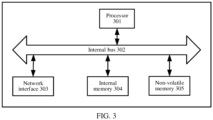
- the present disclosure further provides a schematic structural diagram of an electronic device shown in FIG. 3 .
- the unmanned device includes a processor 301, an internal bus 302, a network interface 303, an internal memory 304, and a non-volatile memory 305, and may further include hardware required for other services.
- the processor reads a corresponding computer program from the non-volatile memory into the internal memory and then executes the computer program, to implement the unmanned device control method described in FIG. 1 .
- the present disclosure does not exclude other implementations, for example, a logic device or a combination of software and hardware. That is, an entity executing the following processing procedure is not limited to the logic units, and may also be hardware or logic devices.
- a programmable logic device for example, a field programmable gate array (FPGA)
- PLD programmable logic device
- FPGA field programmable gate array
- HDL hardware description language
- HDLs for example, advanced Boolean expression language (ABEL), altera hardware description language (AHDL), Confluence, Georgia university programming language (CUPL), HDCal, Java hardware description language (JHDL), Lava, Lola, MyHDL, PALASM, Ruby hardware description language (RHDL), and the like.
- ABEL advanced Boolean expression language
- AHDL altera hardware description language
- CUPL Cornell university programming language
- HDCal Java hardware description language
- JHDL Java hardware description language
- Lava Lola
- MyHDL MyHDL
- PALASM Ruby hardware description language
- RHDL Ruby hardware description language
- VHDL very-high-speed integrated circuit hardware description language
- Verilog Verilog
- the controller may be implemented in any suitable manner, for example, the controller may take the form of, for example, a microprocessor or processor and a computer-readable medium storing computer-readable program code (for example, software or firmware) executable by the microprocessor or processor, a logic gate, a switch, an application-specific integrated circuit (ASIC), a programmable logic controller, and an embedded microcontroller.
- the controller include, but are not limited to, the following microcontrollers: ARC 625D, Atmel AT91SAM, Microchip PIC18F26K20, and Silicone Labs C8051F320.
- the memory controller may also be implemented as part of the memory control logic.
- controller in addition to implementing the controller in the form of pure computer-readable program code, it is also possible to implement, by logically programming the method steps, the controller in the form of a logic gate, a switch, an ASIC, a programmable logic controller, and an embedded microcontroller to achieve the same function.
- a controller may be considered as a hardware component and apparatuses included therein for implementing various functions may also be considered as structures inside the hardware component.
- apparatuses configured to implement various functions may be considered as both software modules implementing the method and structures inside the hardware component.
- the system, the apparatus, the module or the unit described in the foregoing embodiments may be specifically implemented by a computer chip or an entity, or implemented by a product having a certain function.
- a typical implementation device is a computer.
- the computer may be, for example, a personal computer, a laptop computer, a cellular phone, a camera phone, a smartphone, a personal digital assistant, a media player, a navigation device, an email device, a game console, a tablet computer, a wearable device, or a combination of any of these devices.
- the apparatus is divided into units according to functions, which are separately described.
- the functions of the units may be implemented in a same piece of or multiple pieces of software and/or hardware.
- the embodiments of the present disclosure may be provided as a method, a system, or a computer program product. Therefore, the present disclosure may use a form of hardware-only embodiments, software-only embodiments, or embodiments combining software and hardware. In addition, the present disclosure may use a form of a computer program product implemented on one or more computer-usable storage media (including but not limited to a disk memory, a CD-ROM, and an optical memory) including computer-usable program code.
- a computer-usable storage media including but not limited to a disk memory, a CD-ROM, and an optical memory
- These computer program instructions may also be stored in a computer-readable memory that can instruct the computer or another programmable data processing device to work in a specific manner, so that the instructions stored in the computer-readable memory generate an artifact that includes an instruction apparatus.
- the instruction apparatus implements a specific function in one or more procedures in the flowcharts and/or in one or more blocks in the block diagrams.
- These computer program instructions may also be loaded onto a computer or another programmable data processing device, so that a series of operations and steps are performed on the computer or the another programmable device, thereby generating computer-implemented processing. Therefore, the instructions executed on the computer or the another programmable device provide steps for implementing a specific function in one or more procedures in the flowcharts and/or in one or more blocks in the block diagrams.
- a computing device includes one or more processors (CPUs), an input/output interface, a network interface, and an internal memory.
- processors CPUs
- input/output interface input/output interface
- network interface network interface
- internal memory volatile and non-volatile memory
- the internal memory may include a form such as a persistent memory, a random-access memory (RAM) and/or a non-volatile memory of computer readable media, for example, a read-only memory (ROM) or a flash memory (flash RAM).
- RAM random-access memory
- ROM read-only memory
- flash RAM flash memory
- the computer-readable medium includes a non-volatile medium and a volatile medium, a movable medium and a non-movable medium, which may implement storage of information by using any method or technology.
- the information may be a computer-readable instruction, a data structure, a program module, or other data.
- Examples of computer storage media include, but are not limited to, a phase change memory (PRAM), a static random access memory (SRAM), a dynamic random access memory (DRAM), other type of random access memory (RAM), a read-only memory (ROM), an electrically erasable programmable read-only memory (EEPROM), a flash memory or other memory technology, a compact disc read-only memory (CD-ROM), a digital versatile disc (DVD) or other optical storage, a cassette magnetic tape, tape and disk storage or other magnetic storage device or any other non-transmission media that may be configured to store information that a computing device can access.
- the computer-readable medium does not include transitory computer readable media (transitory media), such as a modulated data signal and a carrier.
- the term "include”, “comprise”, or any variant thereof is intended to cover a non-exclusive inclusion. Therefore, a process, a method, a product, or a device that includes a series of elements not only includes such elements, but also includes other elements not expressly listed, or may include elements inherent to the process, the method, the product, or the device. Without further limitations, an element limited by “include a/an" does not exclude other same elements existing in the process, the method, the product, or the device that includes the element.
- the embodiments of the present disclosure may be provided as a method, a system, or a computer program product. Therefore, the present disclosure may use a form of hardware-only embodiments, software-only embodiments, or embodiments combining software and hardware. In addition, the present disclosure may use a form of a computer program product implemented on one or more computer-usable storage media (including but not limited to a disk memory, a CD-ROM, and an optical memory) including computer-usable program code.
- a computer-usable storage media including but not limited to a disk memory, a CD-ROM, and an optical memory
- the present disclosure may be described in the general context of computer-executable instructions executed by a computer, for example, a program module.
- the program module includes a routine, a program, an object, a component, a data structure, and the like for executing a particular task or implementing a particular abstract data type.
- the present disclosure may alternatively be practiced in distributed computing environments in which tasks are executed by remote processing devices that are connected by using a communication network.
- the program module may be located in both local and remote computer storage media including storage devices.
Landscapes
- Engineering & Computer Science (AREA)
- Aviation & Aerospace Engineering (AREA)
- Chemical & Material Sciences (AREA)
- Combustion & Propulsion (AREA)
- Electric Propulsion And Braking For Vehicles (AREA)
- Control Of Electric Motors In General (AREA)
Applications Claiming Priority (2)
| Application Number | Priority Date | Filing Date | Title |
|---|---|---|---|
| CN202111106333.9A CN113859554B (zh) | 2021-09-22 | 2021-09-22 | 一种无人设备控制方法、装置、存储介质及电子设备 |
| PCT/CN2022/086144 WO2023045301A1 (zh) | 2021-09-22 | 2022-04-11 | 无人设备控制 |
Publications (2)
| Publication Number | Publication Date |
|---|---|
| EP4335752A1 true EP4335752A1 (de) | 2024-03-13 |
| EP4335752A4 EP4335752A4 (de) | 2024-09-11 |
Family
ID=78993181
Family Applications (1)
| Application Number | Title | Priority Date | Filing Date |
|---|---|---|---|
| EP22871364.0A Pending EP4335752A4 (de) | 2021-09-22 | 2022-04-11 | Steuerung einer unbemannten vorrichtung |
Country Status (6)
| Country | Link |
|---|---|
| US (1) | US12420939B2 (de) |
| EP (1) | EP4335752A4 (de) |
| JP (1) | JP7802830B2 (de) |
| CN (1) | CN113859554B (de) |
| AU (1) | AU2022350044B2 (de) |
| WO (1) | WO2023045301A1 (de) |
Families Citing this family (1)
| Publication number | Priority date | Publication date | Assignee | Title |
|---|---|---|---|---|
| CN113859554B (zh) * | 2021-09-22 | 2022-12-09 | 北京三快在线科技有限公司 | 一种无人设备控制方法、装置、存储介质及电子设备 |
Family Cites Families (36)
| Publication number | Priority date | Publication date | Assignee | Title |
|---|---|---|---|---|
| JP4133435B2 (ja) * | 2003-02-26 | 2008-08-13 | 健蔵 野波 | 小型無人ヘリコプタの自律制御方法 |
| FR2972364B1 (fr) * | 2011-03-08 | 2014-06-06 | Parrot | Procede de pilotage suivant un virage curviligne d'un drone a voilure tournante a rotors multiples. |
| FR2985329B1 (fr) * | 2012-01-04 | 2015-01-30 | Parrot | Procede de pilotage intuitif d'un drone au moyen d'un appareil de telecommande. |
| FR2985581B1 (fr) * | 2012-01-05 | 2014-11-28 | Parrot | Procede de pilotage d'un drone a voilure tournante pour operer une prise de vue par une camera embarquee avec minimisation des mouvements perturbateurs |
| CA2884597C (en) * | 2012-09-13 | 2022-04-05 | Moog Inc. | Methods and apparatae for controlling and providing a voltage converter with a pulse-width-modulated switch |
| US20170073070A1 (en) * | 2013-02-06 | 2017-03-16 | Zhou Tian Xing | Amphibious vertical takeoff and landing unmanned device with artificial intelligence (AI) and method and system for managing a crisis environment and controlling one or more targets |
| JP5887641B1 (ja) | 2015-05-12 | 2016-03-16 | オービタルワークス株式会社 | 無人飛行体 |
| CN105667768B (zh) * | 2015-12-31 | 2017-11-14 | 歌尔科技有限公司 | 一种无人机起落控制系统和控制方法 |
| US9840324B2 (en) * | 2016-03-28 | 2017-12-12 | Amazon Technologies, Inc. | Selectively thrusting propulsion units for aerial vehicles |
| JP6340384B2 (ja) * | 2016-05-25 | 2018-06-06 | ヤマハ発動機株式会社 | 無人飛行体 |
| WO2018027925A1 (zh) * | 2016-08-12 | 2018-02-15 | 张琬彬 | 无人机多电机的电压分配方法及系统 |
| CN106385208A (zh) * | 2016-11-29 | 2017-02-08 | 深圳市道通智能航空技术有限公司 | 一种永磁同步电机启动方法、装置和无人飞行器 |
| CN106655979B (zh) | 2016-12-01 | 2019-07-26 | 广州极飞科技有限公司 | 飞行器及其电子调速器的过压保护方法和装置 |
| US10293957B2 (en) * | 2017-01-30 | 2019-05-21 | Hanhui Zhang | Rotary wing unmanned aerial vehicle and pneumatic launcher |
| DE102017111911A1 (de) * | 2017-05-31 | 2018-12-06 | Dirk Brunner | Antriebssystem für ein Fahrzeug |
| WO2019000273A1 (zh) * | 2017-06-28 | 2019-01-03 | 深圳市大疆创新科技有限公司 | 一种控制无人机的方法、设备、系统及存储介质 |
| CN110799420B (zh) * | 2017-06-30 | 2023-07-21 | 加拿大空客有限合伙公司 | 用于控制起飞推力的系统和方法 |
| US10988247B2 (en) * | 2017-10-19 | 2021-04-27 | Uvionix Aerospace Corporation | Unmanned aerial vehicle and propulsion system for an unmanned aerial vehicle |
| US10766610B2 (en) * | 2018-01-22 | 2020-09-08 | Mattel, Inc. | Unmanned aerial vehicle with propeller guard |
| JP2019161714A (ja) * | 2018-03-08 | 2019-09-19 | 株式会社東芝 | モータ制御装置およびプログラム |
| CN108390603B (zh) * | 2018-03-08 | 2019-12-31 | 深圳市道通智能航空技术有限公司 | 电机控制方法、其装置及无人机控制系统 |
| CN110554703A (zh) * | 2018-06-04 | 2019-12-10 | 百度在线网络技术(北京)有限公司 | 无人机飞行姿态调整方法、设备及存储介质 |
| WO2019235418A1 (ja) * | 2018-06-04 | 2019-12-12 | 株式会社ナイルワークス | ドローンシステム、ドローン、操縦器、ドローンシステムの制御方法、および、ドローンシステム制御プログラム |
| JP2019221078A (ja) * | 2018-06-21 | 2019-12-26 | パナソニックIpマネジメント株式会社 | モータ駆動装置、およびその制御方法 |
| US20200026269A1 (en) * | 2018-07-19 | 2020-01-23 | Aurora Flight Sciences Corporation | Performance monitoring system for an electric drive system |
| US11697497B2 (en) * | 2018-10-03 | 2023-07-11 | Sarcos Corp. | Aerial vehicles having countermeasures deployed from a platform for neutralizing target aerial vehicles |
| GB2583971A (en) * | 2019-05-16 | 2020-11-18 | Autonomous Devices Ltd | Control arrangement for fluid borne vehicles |
| JP7342523B2 (ja) * | 2019-08-28 | 2023-09-12 | 株式会社デンソー | 電動垂直離着陸機および電動垂直離着陸機の制御装置 |
| CN110654536B (zh) | 2019-09-20 | 2020-11-20 | 仿翼(北京)科技有限公司 | 飞行器、飞行器的控制方法、装置及计算机可读存储介质 |
| US11334065B2 (en) * | 2020-01-10 | 2022-05-17 | Prince Sultan University | System, apparatus, and method for controlling unmanned aerial vehicles for search and rescue |
| WO2021212520A1 (zh) * | 2020-04-24 | 2021-10-28 | 深圳市大疆创新科技有限公司 | 电机的控制方法、装置、设备及存储介质 |
| US11614754B2 (en) * | 2020-08-11 | 2023-03-28 | Pitch Aeronautics LLC | Multirotor vertical takeoff and landing aircraft with cyclorotor for lateral control |
| KR102200269B1 (ko) * | 2020-08-13 | 2021-01-11 | (주)다츠 | 무인 비행체 및 이를 포함하는 자폭 무인기 운용 시스템 |
| CN112731957B (zh) * | 2021-04-06 | 2021-09-07 | 北京三快在线科技有限公司 | 无人机的控制方法、装置、计算机可读存储介质及无人机 |
| CN112987797B (zh) * | 2021-05-12 | 2021-08-24 | 北京三快在线科技有限公司 | 无人机控制方法、装置、存储介质及无人机 |
| CN113859554B (zh) * | 2021-09-22 | 2022-12-09 | 北京三快在线科技有限公司 | 一种无人设备控制方法、装置、存储介质及电子设备 |
-
2021
- 2021-09-22 CN CN202111106333.9A patent/CN113859554B/zh active Active
-
2022
- 2022-04-11 WO PCT/CN2022/086144 patent/WO2023045301A1/zh not_active Ceased
- 2022-04-11 JP JP2023574597A patent/JP7802830B2/ja active Active
- 2022-04-11 EP EP22871364.0A patent/EP4335752A4/de active Pending
- 2022-04-11 US US18/570,634 patent/US12420939B2/en active Active
- 2022-04-11 AU AU2022350044A patent/AU2022350044B2/en active Active
Also Published As
| Publication number | Publication date |
|---|---|
| JP2024521922A (ja) | 2024-06-04 |
| AU2022350044A1 (en) | 2024-01-04 |
| CN113859554B (zh) | 2022-12-09 |
| AU2022350044B2 (en) | 2025-02-27 |
| EP4335752A4 (de) | 2024-09-11 |
| WO2023045301A1 (zh) | 2023-03-30 |
| US12420939B2 (en) | 2025-09-23 |
| JP7802830B2 (ja) | 2026-01-20 |
| CN113859554A (zh) | 2021-12-31 |
| US20240286752A1 (en) | 2024-08-29 |
Similar Documents
| Publication | Publication Date | Title |
|---|---|---|
| CN111665844B (zh) | 一种路径规划方法及装置 | |
| US12151709B2 (en) | Trajectory prediction method and apparatus, storage medium, and electronic device | |
| EP3171234B1 (de) | Steuerungsvorrichtung, steuerungsverfahren, informationsverarbeitungsprogramm und aufzeichnungsmedium | |
| US11881797B2 (en) | Electric motor power control systems | |
| EP4335752A1 (de) | Steuerung einer unbemannten vorrichtung | |
| US20200324901A1 (en) | Control method for unmanned aerial vehicle, flight controller and unmanned aerial vehicle | |
| CN111532285B (zh) | 一种车辆控制方法及装置 | |
| HK40102240A (en) | Unmanned device control | |
| CN105676863A (zh) | 无人飞行器的控制方法及控制装置 | |
| US12282341B2 (en) | Unmanned device control method and apparatus, storage medium, and electronic device | |
| US9933828B2 (en) | Controlling power consumption of a voltage regulator in a computer system | |
| CN112731957B (zh) | 无人机的控制方法、装置、计算机可读存储介质及无人机 | |
| US20250256412A1 (en) | Method for controlling mechanical finger, and device, and storage medium | |
| CN119134586A (zh) | 一种考虑荷电状态的储能调控方法、装置、设备及介质 | |
| US20220334579A1 (en) | Unmanned device control | |
| US11897346B2 (en) | Electrical motor power control systems | |
| US20240178692A1 (en) | Charge/discharge control method, charging device, and storage medium | |
| US11987243B2 (en) | Vehicle, program and notification method | |
| CN116767503A (zh) | 一种起降平台、无人机停靠位姿调整方法及装置 | |
| CN115783318A (zh) | 一种气浮台及其控制方法、装置、存储介质及电子设备 | |
| CN114545912A (zh) | 一种自动驾驶设备控制方法、装置、存储介质及电子设备 | |
| CN116767506A (zh) | 一种无人机的停靠位姿调整方法及装置 | |
| CN108462428B (zh) | 电机速度调节方法及装置、计算机可读存储介质、终端 | |
| CN113589707A (zh) | 一种增强现实的自动驾驶系统测试方法及装置 | |
| CN116080903B (zh) | 一种配送无人机、配送无人机预警方法及装置 |
Legal Events
| Date | Code | Title | Description |
|---|---|---|---|
| STAA | Information on the status of an ep patent application or granted ep patent |
Free format text: STATUS: THE INTERNATIONAL PUBLICATION HAS BEEN MADE |
|
| PUAI | Public reference made under article 153(3) epc to a published international application that has entered the european phase |
Free format text: ORIGINAL CODE: 0009012 |
|
| STAA | Information on the status of an ep patent application or granted ep patent |
Free format text: STATUS: REQUEST FOR EXAMINATION WAS MADE |
|
| 17P | Request for examination filed |
Effective date: 20231205 |
|
| AK | Designated contracting states |
Kind code of ref document: A1 Designated state(s): AL AT BE BG CH CY CZ DE DK EE ES FI FR GB GR HR HU IE IS IT LI LT LU LV MC MK MT NL NO PL PT RO RS SE SI SK SM TR |
|
| REG | Reference to a national code |
Ref country code: HK Ref legal event code: DE Ref document number: 40102240 Country of ref document: HK |
|
| A4 | Supplementary search report drawn up and despatched |
Effective date: 20240813 |
|
| RIC1 | Information provided on ipc code assigned before grant |
Ipc: B64C 39/02 20230101ALI20240808BHEP Ipc: B64D 27/24 20240101ALI20240808BHEP Ipc: B64D 31/06 20240101AFI20240808BHEP |
|
| DAV | Request for validation of the european patent (deleted) | ||
| DAX | Request for extension of the european patent (deleted) |