EP4335677A1 - Guide rail assembly and automobile with same - Google Patents
Guide rail assembly and automobile with same Download PDFInfo
- Publication number
- EP4335677A1 EP4335677A1 EP23195522.0A EP23195522A EP4335677A1 EP 4335677 A1 EP4335677 A1 EP 4335677A1 EP 23195522 A EP23195522 A EP 23195522A EP 4335677 A1 EP4335677 A1 EP 4335677A1
- Authority
- EP
- European Patent Office
- Prior art keywords
- guide rail
- sealing strip
- cover plate
- rail body
- rail assembly
- Prior art date
- Legal status (The legal status is an assumption and is not a legal conclusion. Google has not performed a legal analysis and makes no representation as to the accuracy of the status listed.)
- Pending
Links
Images




Classifications
-
- B—PERFORMING OPERATIONS; TRANSPORTING
- B60—VEHICLES IN GENERAL
- B60J—WINDOWS, WINDSCREENS, NON-FIXED ROOFS, DOORS, OR SIMILAR DEVICES FOR VEHICLES; REMOVABLE EXTERNAL PROTECTIVE COVERINGS SPECIALLY ADAPTED FOR VEHICLES
- B60J10/00—Sealing arrangements
- B60J10/70—Sealing arrangements specially adapted for windows or windscreens
- B60J10/74—Sealing arrangements specially adapted for windows or windscreens for sliding window panes, e.g. sash guides
- B60J10/76—Sealing arrangements specially adapted for windows or windscreens for sliding window panes, e.g. sash guides for window sashes; for glass run channels
-
- B—PERFORMING OPERATIONS; TRANSPORTING
- B60—VEHICLES IN GENERAL
- B60J—WINDOWS, WINDSCREENS, NON-FIXED ROOFS, DOORS, OR SIMILAR DEVICES FOR VEHICLES; REMOVABLE EXTERNAL PROTECTIVE COVERINGS SPECIALLY ADAPTED FOR VEHICLES
- B60J10/00—Sealing arrangements
- B60J10/30—Sealing arrangements characterised by the fastening means
-
- B—PERFORMING OPERATIONS; TRANSPORTING
- B60—VEHICLES IN GENERAL
- B60J—WINDOWS, WINDSCREENS, NON-FIXED ROOFS, DOORS, OR SIMILAR DEVICES FOR VEHICLES; REMOVABLE EXTERNAL PROTECTIVE COVERINGS SPECIALLY ADAPTED FOR VEHICLES
- B60J10/00—Sealing arrangements
- B60J10/45—Assembling sealing arrangements with vehicle parts
-
- B—PERFORMING OPERATIONS; TRANSPORTING
- B60—VEHICLES IN GENERAL
- B60J—WINDOWS, WINDSCREENS, NON-FIXED ROOFS, DOORS, OR SIMILAR DEVICES FOR VEHICLES; REMOVABLE EXTERNAL PROTECTIVE COVERINGS SPECIALLY ADAPTED FOR VEHICLES
- B60J10/00—Sealing arrangements
- B60J10/70—Sealing arrangements specially adapted for windows or windscreens
- B60J10/74—Sealing arrangements specially adapted for windows or windscreens for sliding window panes, e.g. sash guides
- B60J10/78—Sealing arrangements specially adapted for windows or windscreens for sliding window panes, e.g. sash guides adjacent to corner pieces, mirror supports or quarter windows
-
- B—PERFORMING OPERATIONS; TRANSPORTING
- B60—VEHICLES IN GENERAL
- B60J—WINDOWS, WINDSCREENS, NON-FIXED ROOFS, DOORS, OR SIMILAR DEVICES FOR VEHICLES; REMOVABLE EXTERNAL PROTECTIVE COVERINGS SPECIALLY ADAPTED FOR VEHICLES
- B60J10/00—Sealing arrangements
- B60J10/70—Sealing arrangements specially adapted for windows or windscreens
- B60J10/74—Sealing arrangements specially adapted for windows or windscreens for sliding window panes, e.g. sash guides
- B60J10/79—Sealing arrangements specially adapted for windows or windscreens for sliding window panes, e.g. sash guides for flush-glass windows, i.e. for windows flush with the vehicle body or the window frame
Definitions
- the present utility model relates to the technical field of automotive manufacturing, and in particular to a guide rail assembly and an automobile with the same.
- the guide rail structure of the A-pillar quarter window glass of the existing automobile includes an internal guide rail, a guide groove, an external guide rail, and the like.
- the exterior rail vertically snaps into the interior guide rail
- the outer guide rail is an inverted T-shaped female sheet structure
- the top end of the outer rail vertical structure snaps within the bottom end of the inner rail vertical structure
- the arc protrusion structure on one side of the outer guide rail is snap-fitted with the bottom of the guide groove.
- the main purpose of the present utility model is to provide a guide rail assembly and an automobile with same, aiming to improve the convenience of assembling the guide rail assembly and reduce the manufacturing cost.
- a guide rail assembly comprising:
- the slot bottom of the snapping slot is concavely provided with a first embedding cavity and a second embedding cavity
- the sealing strip is convexly provided with a first protrusion embedded in the first embedding cavity and a second protrusion embedded in the second embedding cavity.
- the sealing strip comprises a first sealing strip and a second sealing strip connected with the first sealing strip, the first sealing strip disposed corresponding to the supporting section and used to seal the gap between the side edge of the triangular glass and the guide rail body, and the second sealing strip disposed corresponding to the fixing section and used to seal the gap between the guide rail body and the lifting glass.
- the cross-section of the cover plate is disposed in a "V" shape.
- the cover plate is convexly provided with a stopper, and a raised bar in abutment with the stopper is disposed at the position of the sealing strip corresponding to the stopper, the stopper is used to limit the movement of the sealing strip along the width direction of the cover plate.
- the material of the cover plate is plastic
- the cover plate is provided with a limiting notch
- a bump which snap-fits with the limiting notch is disposed at the position of the sealing strip corresponding to the limiting notch, and the bump is snapped into the limiting notch, so as to limit the movement of the sealing strip along the length direction of the guide rail body.
- the material of the guide rail body is aluminum, and its surface is sprayed with paint.
- the fixing bracket and the guide rail body are fixed by riveting or welding.
- cover plate and the guide rail body are connected and fixed by screws.
- the present utility model also proposes an automobile including the guide rail assembly as described above, and the guide rail assembly includes:
- the guide rail assembly comprises a guide rail body, a cover plate and a fixing bracket;
- the guide rail body is provided with a snapping slot and a mounting edge adjacent to the snapping slot along its length direction, and the mounting edge comprises a supporting section and a fixing section connected with the supporting section, and a sealing strip snaps into the snapping slot for sealing the gap between the guide rail body and the side edge of triangular glass and sealing the gap between the guide rail body and lifting glass;
- the supporting section is suitable for carrying the side edge of triangular glass; one side of the cover plate is fixed on the fixing section, and the other side of the cover plate at least partially covers the sealing strip;
- the fixing bracket is disposed on the fixing section for fixing the guide rail body to the door sheet metal.
- the guide rail body can be integrally pre-formed with the snapping slot and the mounting edge.
- the sealing strip can be firstly snapped or bonded in the snapping slot, then the fixing bracket is installed, and then the fixing section at the lower end of the guide rail body can be covered with a cover plate.
- the present utility model reduces the number of parts of the guide rail assembly, simplifies the installation process, improves the convenience of assembly of the guide rail assembly, and reduces the manufacturing cos.
- the sealing between the guide rail assembly and the triangular glass, and between the guide rail assembly and the lifting glass is also improved.
- the directional indication is only used to explain the relative positional relationship, motion conditions, etc. between the components in a certain posture (as shown in the accompanying drawing). If the specific posture changes, the directional indication will also change therewith accordingly.
- the present utility model proposes a guide rail assembly, which is suitable for installing the triangular glass of the A-pillar of the automobile, but not limited to this.
- the guide rail assembly 100 includes a guide rail body 10, a cover plate 20 and a fixing bracket 30; the guide rail body 10 is provided with a snapping slot 10a and a mounting edge 110 adjacent to the snapping slot 10a along its length direction, and the mounting edge 1 10 includes a supporting section 11 and a fixing section 12 connected with the supporting section 11, and a sealing strip 40 snaps into the snapping slot 10a for sealing the gap between the guide rail body 10 and the side edge of the triangular glass 200 and sealing the gap between the guide rail body 10 and the lifting glass; wherein, the supporting section 11 is suitable for carrying the side edge of the triangular glass 200; one side of the cover plate 20 is fixed on the fixing section 12, and the other side of the cover plate 20 at least partially covers the sealing strip 40; the fixing bracket 30 is disposed on the fixing section 12 for fixing the guide rail body 10 on the door sheet metal.
- the guide rail body 10 can be integrally formed with structures such as the snapping slot 10a, the supporting section 11 of the mounting edge 110, and the fixing section 12, etc, and the guide rail body 10 can be made of metal material, especially aluminum, but not limited to this.
- the surface of the guide rail body 10 can be sprayed with paint, such as high-gloss black paint, to improve aesthetics and oxidation corrosion resistance.
- the guide rail can be provided with a mounting edge 110 along its length direction, its supporting section 11 may be arranged flush with the fixing section 12, and a portion of the cover plate 20 fixed to the fixing section 12 can also be arranged flush with the triangular glass 200, so as to ensure zero steps at the joint and improve the overall aesthetics.
- cover plate 20 and the guide rail body 10 can be connected and fixed by the way of screws or snap-fit, etc.
- the cover plate 20 can be made of plastic material, especially PA66, but not limited to this.
- the fixing bracket 30 can be a metal piece, and the fixing bracket 30 and the guide rail body 10 can be fixed by the way of riveting, welding or threading, etc.
- the fixing bracket 30 may be an integrally formed component, or may be an assembly assembled from a plurality of components, but not limited to this.
- the guide rail body 10 can be integrally pre-formed with structures such as the snapping slot 10a and the mounting edge 110.
- the sealing strip 40 is firstly snapped or bonded in the snapping slot 10a, then the fixing bracket 30 is installed, and then the fixing section 12 at the lower end of the guide rail body 10 can be covered with a cover plate 20.
- the present utility model reduces the number of parts of the guide rail assembly 100, simplifies the installation process, improves the convenience of assembly of the guide rail assembly 100, and reduces the manufacturing cost.
- the sealing between the guide rail assembly and the triangular glass, and between the guide rail assembly and the lifting glass is also improved.
- the slot bottom of the snapping slot 10a can be concavely provided with a first embedding cavity 10a1 and a second embedding cavity 10a2
- the slot bottom of the snapping slot 10a is concavely provided with a first embedding cavity 10a1 and a second embedding cavity 10a2
- the sealing strip 40 is convexly provided with a first protrusion embedded into the first insertion cavity 10a1 and a second portion embedded into the second insertion cavity 10a2.
- the sealing strip 40 may include a first sealing strip and a second sealing strip connected with the first sealing strip.
- the first sealing strip 40 disposed corresponding to the supporting section 11 is used to seal the gap between the side edge of the triangular glass 200 and the guide rail body 10
- the second sealing strip 40 disposed corresponding to the fixing section 12 is used to seal the gap between the guide rail body 10 and the lift glass.
- the first sealing strip and the second sealing strip can be extruded separately, and then connected together by injection molding.
- the material of the first sealing strip and the second sealing strip can be EPDM, but not limited to this.
- the cross section of the cover plate 20 may be disposed in a "V" shape to cover the sealing strip 40 at the lower end of the guide rail body 10.
- the cover plate 20 of this structure is easy to be machined and easy to assemble, further improving the sealing and aesthetics.
- the inner side of the cover plate 20 can be convexly provided with a stopper 21, and a raised bar in abutment with the stopper 21 is disposed at the position of the top portion of the sealing strip 40 corresponding to the stopper 21can be provided with to limit the movement of the sealing strip 40 along the width direction of the cover plate 20.
- the stability of the sealing strip 40 is improved, and the movement of the sealing strip 40 is avoided from affecting the sealing performance.
- the cover plate 20 is provided with a limiting notch 20a, a bump 41 which snap-fits with the limiting notch 20a is disposed at the position of the sealing strip 40 corresponding to the limiting notch 20a, and the bump 41 is snapped into the limiting notch 20a to limit the movement of the sealing strip 40 along the length direction of the guide rail body 10.
- the present utility model also proposes an automobile, which includes a guide rail assembly 100, the specific structure of which refers to the above-mentioned embodiments. Since the automobile proposed by the present utility model includes all the solutions of all the embodiments of the above-mentioned guide rail assembly 100, it has at least the same technical effect as that of the guide rail assembly 100, which will not be elaborated here one by one.
Landscapes
- Engineering & Computer Science (AREA)
- Mechanical Engineering (AREA)
- Window Of Vehicle (AREA)
- Civil Engineering (AREA)
- Structural Engineering (AREA)
Abstract
Description
- The present utility model relates to the technical field of automotive manufacturing, and in particular to a guide rail assembly and an automobile with the same.
- The guide rail structure of the A-pillar quarter window glass of the existing automobile includes an internal guide rail, a guide groove, an external guide rail, and the like. The exterior rail vertically snaps into the interior guide rail, the outer guide rail is an inverted T-shaped female sheet structure, the top end of the outer rail vertical structure snaps within the bottom end of the inner rail vertical structure, and the arc protrusion structure on one side of the outer guide rail is snap-fitted with the bottom of the guide groove. During the assembly process, since the guide rail structure of the quarter window is composed of many parts, its installation is relatively cumbersome, and its manufacturing cost is relatively high.
- The main purpose of the present utility model is to provide a guide rail assembly and an automobile with same, aiming to improve the convenience of assembling the guide rail assembly and reduce the manufacturing cost.
- In order to achieve the above purpose, the present utility model proposes a guide rail assembly, comprising:
- a guide rail body provided with a snapping slot and a mounting edge adjacent to the snapping slot along its length direction, wherein the mounting edge includes a supporting section and a fixing section connected with the supporting section, and a sealing strip snaps into the snapping slot for sealing the gap between the guide rail body and the side edge of the triangular glass and sealing the gap between the guide rail body and the lifting glass; wherein, the supporting section is suitable for carrying the side edge of the triangular glass;
- a cover plate, one side of the cover plate is fixed on the fixing section, and the other side of the cover plate at least partially covers the sealing strip; and
- a fixing bracket disposed on the fixing section to fix the guide rail body onto the door sheet metal.
- Optionally, the slot bottom of the snapping slot is concavely provided with a first embedding cavity and a second embedding cavity, and the sealing strip is convexly provided with a first protrusion embedded in the first embedding cavity and a second protrusion embedded in the second embedding cavity.
- Optionally, the sealing strip comprises a first sealing strip and a second sealing strip connected with the first sealing strip, the first sealing strip disposed corresponding to the supporting section and used to seal the gap between the side edge of the triangular glass and the guide rail body, and the second sealing strip disposed corresponding to the fixing section and used to seal the gap between the guide rail body and the lifting glass.
- Optionally, the cross-section of the cover plate is disposed in a "V" shape.
- Optionally, the cover plate is convexly provided with a stopper, and a raised bar in abutment with the stopper is disposed at the position of the sealing strip corresponding to the stopper, the stopper is used to limit the movement of the sealing strip along the width direction of the cover plate.
- Optionally, the material of the cover plate is plastic, the cover plate is provided with a limiting notch, and a bump which snap-fits with the limiting notch is disposed at the position of the sealing strip corresponding to the limiting notch, and the bump is snapped into the limiting notch, so as to limit the movement of the sealing strip along the length direction of the guide rail body.
- Optionally, the material of the guide rail body is aluminum, and its surface is sprayed with paint.
- Optionally, the fixing bracket and the guide rail body are fixed by riveting or welding.
- Optionally, the cover plate and the guide rail body are connected and fixed by screws.
- In order to achieve the above object, the present utility model also proposes an automobile including the guide rail assembly as described above, and the guide rail assembly includes:
- a guide rail body provided with a snapping slot and a mounting edge adjacent to the snapping slot along its length direction, wherein the mounting edge includes a supporting section and a fixing section connected with the supporting section, and a sealing strip snaps into the snapping slot for sealing the gap between the guide rail body and the side edge of the triangular glass and sealing the gap between the guide rail body and the lifting glass; wherein, the supporting section is suitable for carrying the side edge of the triangular glass;
- a cover plate, one side of the cover plate is fixed on the fixing section, and the other side of the cover plate at least partially covers the sealing strip; and
- a fixing bracket disposed on the fixing section to fix the guide rail body onto the door sheet metal.
- In the technical solution of the present utility model, the guide rail assembly comprises a guide rail body, a cover plate and a fixing bracket; the guide rail body is provided with a snapping slot and a mounting edge adjacent to the snapping slot along its length direction, and the mounting edge comprises a supporting section and a fixing section connected with the supporting section, and a sealing strip snaps into the snapping slot for sealing the gap between the guide rail body and the side edge of triangular glass and sealing the gap between the guide rail body and lifting glass; wherein, the supporting section is suitable for carrying the side edge of triangular glass; one side of the cover plate is fixed on the fixing section, and the other side of the cover plate at least partially covers the sealing strip; the fixing bracket is disposed on the fixing section for fixing the guide rail body to the door sheet metal. It can be understood that the guide rail body can be integrally pre-formed with the snapping slot and the mounting edge. During production and assembly, the sealing strip can be firstly snapped or bonded in the snapping slot, then the fixing bracket is installed, and then the fixing section at the lower end of the guide rail body can be covered with a cover plate. The present utility model reduces the number of parts of the guide rail assembly, simplifies the installation process, improves the convenience of assembly of the guide rail assembly, and reduces the manufacturing cos. At the same time, the sealing between the guide rail assembly and the triangular glass, and between the guide rail assembly and the lifting glass is also improved.
- In order to illustrate the technical solutions in the embodiments of the present utility model or the prior art more clearly, the following will briefly introduce the accompanying drawings that need to be used in the description of the embodiments or the prior art. Obviously, the accompanying drawings in the following description are only some embodiments of the present utility model, and it is also possible for those skilled in the art to obtain other drawings according to the structures shown in these drawings without creative work.
-
Fig. 1 is a structural schematic diagram of an embodiment of the guide rail assembly of the present utility model; -
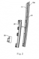
Fig. 2 is an exploded view of an embodiment of the guide rail assembly of the present utility model; -
Fig. 3 is a structural schematic diagram of an embodiment of the guide rail assembly and the triangular glass of the present utility model; -
Fig. 4 is a cross-sectional view at A-A inFig. 3 ; -
Fig. 5 is a cross-sectional view at B-B inFig. 3 ; -
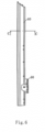
Fig. 6 is a back view of the guide rail assembly in an embodiment of a guide rail assembly of the present utility model; -
Fig. 7 is a cross-sectional view at C-C inFig. 6 ; -
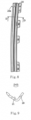
Fig. 8 is a structural schematic diagram of a cover plate in an embodiment of a guide rail assembly of the present utility model; -
Fig. 9 is a cross-sectional view at D-D inFig. 8 . - 10. guide rail body; 20. cover plate; 30. fixing bracket; 40. sealing strip; 10a. snapping slot; 110. mounting edge; 11. supporting section; 12. fixing section; 10a1. first embedding cavity; 10a2. second embedding cavity; 21. stopper; 20a. limiting notch; 41. bump; 100. guide rail assembly; 200. triangular glass.
- The realization of the purpose, functional characteristics and advantages of the present utility model will be further illustrated in conjunction with the embodiments and with reference to the accompanying drawings.
- The technical solutions in the embodiments of the present utility model will be clearly and completely described below in conjunction with the accompanying drawings in the embodiments of the present utility model. Obviously, the described embodiments are only a portion of the embodiments of the present utility model, not all of them. Based on the embodiments in the present utility model, all other embodiments obtained by persons of ordinary skill in the art without making creative efforts belong to the scope protected by the present utility model.
- It should be noted that if there is a directional indication (such as up, down, left, right, front, back...) involved in the embodiment of the present utility model, the directional indication is only used to explain the relative positional relationship, motion conditions, etc. between the components in a certain posture (as shown in the accompanying drawing). If the specific posture changes, the directional indication will also change therewith accordingly.
- In addition, if there are descriptions involving "first", "second", etc. in the embodiments of the present utility model, the descriptions of "first", "second", etc. are for descriptive purposes only, and cannot be understood indicate or suggest their relative importance or implying the number of technical features indicated. Thus, the features defined with "first" and "second" may explicitly or implicitly include at least one of these features. In addition, if "and/or" appearing in the whole text means including three parallel schemes, then taking "A and/or B" as an example, it includes scheme A, or scheme B, or a scheme that both A and B are satisfied simultaneously. In addition, the technical solutions of the various embodiments can be combined with each other, but must take that those skilled in the art can realize as a basis. When the combination of technical solutions is contradictory or cannot be realized, such a combination of technical solutions should be considered to be absent, and to be not within the protection scope claimed by the present utility model, either.
- The present utility model proposes a guide rail assembly, which is suitable for installing the triangular glass of the A-pillar of the automobile, but not limited to this.
- Referring to
Figs. 1 to 5 , in an embodiment of the present utility model, theguide rail assembly 100 includes aguide rail body 10, acover plate 20 and a fixingbracket 30; theguide rail body 10 is provided with asnapping slot 10a and a mountingedge 110 adjacent to thesnapping slot 10a along its length direction, and the mounting edge 1 10 includes a supportingsection 11 and a fixingsection 12 connected with the supportingsection 11, and a sealingstrip 40 snaps into the snappingslot 10a for sealing the gap between theguide rail body 10 and the side edge of thetriangular glass 200 and sealing the gap between theguide rail body 10 and the lifting glass; wherein, the supportingsection 11 is suitable for carrying the side edge of thetriangular glass 200; one side of thecover plate 20 is fixed on the fixingsection 12, and the other side of thecover plate 20 at least partially covers the sealingstrip 40; the fixingbracket 30 is disposed on the fixingsection 12 for fixing theguide rail body 10 on the door sheet metal. - In this embodiment, the
guide rail body 10 can be integrally formed with structures such as the snappingslot 10a, the supportingsection 11 of the mountingedge 110, and the fixingsection 12, etc, and theguide rail body 10 can be made of metal material, especially aluminum, but not limited to this. - The surface of the
guide rail body 10 can be sprayed with paint, such as high-gloss black paint, to improve aesthetics and oxidation corrosion resistance. - Referring to
Fig. 2 ,Fig. 4 andFig. 5 , in this embodiment, the guide rail can be provided with a mountingedge 110 along its length direction, its supportingsection 11 may be arranged flush with the fixingsection 12, and a portion of thecover plate 20 fixed to the fixingsection 12 can also be arranged flush with thetriangular glass 200, so as to ensure zero steps at the joint and improve the overall aesthetics. - In this embodiment, the
cover plate 20 and theguide rail body 10 can be connected and fixed by the way of screws or snap-fit, etc. Thecover plate 20 can be made of plastic material, especially PA66, but not limited to this. - The fixing
bracket 30 can be a metal piece, and the fixingbracket 30 and theguide rail body 10 can be fixed by the way of riveting, welding or threading, etc. The fixingbracket 30 may be an integrally formed component, or may be an assembly assembled from a plurality of components, but not limited to this. - It can be understood that the
guide rail body 10 can be integrally pre-formed with structures such as the snappingslot 10a and the mountingedge 110. During production and assembly, the sealingstrip 40 is firstly snapped or bonded in thesnapping slot 10a, then the fixingbracket 30 is installed, and then the fixingsection 12 at the lower end of theguide rail body 10 can be covered with acover plate 20. The present utility model reduces the number of parts of theguide rail assembly 100, simplifies the installation process, improves the convenience of assembly of theguide rail assembly 100, and reduces the manufacturing cost. At the same time, the sealing between the guide rail assembly and the triangular glass, and between the guide rail assembly and the lifting glass is also improved. - In order to improve the reliability of the connection between the
guide rail body 10 and the sealingstrip 40, and to avoid the sealing performance being affected by theseal bar 40 disengaging from the installed position, referring toFig.4 andFig.5 , in an embodiment, the slot bottom of the snappingslot 10a can be concavely provided with a first embedding cavity 10a1 and a second embedding cavity 10a2, the slot bottom of the snappingslot 10a is concavely provided with a first embedding cavity 10a1 and a second embedding cavity 10a2, and the sealingstrip 40 is convexly provided with a first protrusion embedded into the first insertion cavity 10a1 and a second portion embedded into the second insertion cavity 10a2. - In this embodiment, the sealing
strip 40 may include a first sealing strip and a second sealing strip connected with the first sealing strip. Thefirst sealing strip 40 disposed corresponding to the supportingsection 11 is used to seal the gap between the side edge of thetriangular glass 200 and theguide rail body 10, and thesecond sealing strip 40 disposed corresponding to the fixingsection 12 is used to seal the gap between theguide rail body 10 and the lift glass. - The first sealing strip and the second sealing strip can be extruded separately, and then connected together by injection molding. The material of the first sealing strip and the second sealing strip can be EPDM, but not limited to this.
- Referring to
FIG. 8 and FIG. 9 , in an embodiment, the cross section of thecover plate 20 may be disposed in a "V" shape to cover the sealingstrip 40 at the lower end of theguide rail body 10. Thecover plate 20 of this structure is easy to be machined and easy to assemble, further improving the sealing and aesthetics. - Please in conjunction with
FIG. 5 andFIG. 9 , in this embodiment, the inner side of thecover plate 20 can be convexly provided with astopper 21, and a raised bar in abutment with thestopper 21 is disposed at the position of the top portion of the sealingstrip 40 corresponding to the stopper 21can be provided with to limit the movement of the sealingstrip 40 along the width direction of thecover plate 20. As such, the stability of the sealingstrip 40 is improved, and the movement of the sealingstrip 40 is avoided from affecting the sealing performance. - In order to further avoid sealing failure of the sealing
strip 40 to improve the stability of theguide rail assembly 100, referring toFIG. 2 , referring toFIG. 3 andFIG.8 , in an embodiment, thecover plate 20 is provided with a limitingnotch 20a, abump 41 which snap-fits with the limitingnotch 20a is disposed at the position of the sealingstrip 40 corresponding to the limitingnotch 20a, and thebump 41 is snapped into the limitingnotch 20a to limit the movement of the sealingstrip 40 along the length direction of theguide rail body 10. - The present utility model also proposes an automobile, which includes a
guide rail assembly 100, the specific structure of which refers to the above-mentioned embodiments. Since the automobile proposed by the present utility model includes all the solutions of all the embodiments of the above-mentionedguide rail assembly 100, it has at least the same technical effect as that of theguide rail assembly 100, which will not be elaborated here one by one. - What is described above is only an optional embodiment of the present utility model, and does not therefore limit the patent scope of the present utility model. Under the inventive concept of the present utility model, the equivalent structural transformation made by using the specification and the contents of the accompanying drawings of the present utility model, or their direct/indirect applications in other related technical fields are all included in the patent protection scope of the present utility model.
Claims (10)
- A guide rail assembly, characterized in that, comprising:a guide rail body provided with a snapping slot and a mounting edge adjacent to the snapping slot along its length direction, wherein the mounting edge includes a supporting section and a fixing section connected with the supporting section, and a sealing strip snaps into the snapping slot for sealing the gap between the guide rail body and the side edge of the triangular glass and sealing the gap between the guide rail body and the lifting glass; wherein, the supporting section is suitable for carrying the side edge of the triangular glass;a cover plate, one side of the cover plate is fixed on the fixing section, and the other side of the cover plate at least partially covers the sealing strip; anda fixing bracket disposed on the fixing section to fix the guide rail body onto the door sheet metal.
- The guide rail assembly according to claim 1, characterized in that, the slot bottom of the snapping slot is concavely provided with a first embedding cavity and a second embedding cavity, and the sealing strip is convexly provided with a first protrusion embedded in the first embedding cavity and a second protrusion embedded in the second embedding cavity.
- The guide rail assembly according to claim 2, characterized in that, the sealing strip comprises a first sealing strip and a second sealing strip connected with the first sealing strip, the first sealing strip disposed corresponding to the supporting section is used to seal the gap between the side edge of the triangular glass and the guide rail body, and the second sealing strip disposed corresponding to the fixing section is used to seal the gap between the guide rail body and the lifting glass.
- The guide rail assembly according to claim 1, characterized in that, the cross-section of the cover plate is disposed in a "V" shape.
- The guide rail assembly according to claim 4, characterized in that, the cover plate is convexly provided with a stopper, and a raised bar in abutment with the stopper is disposed at the position of the sealing strip corresponding to the stopper, the stopper is used to limit the movement of the sealing strip along the width direction of the cover plate.
- The guide rail assembly according to claim 1, characterized in that, the material of the cover plate is plastic, the cover plate is provided with a limiting notch, and a bump which snap-fits with the limiting notch is disposed at the position of the sealing strip corresponding to the limiting notch, and the bump is snapped into the limiting notch, so as to limit the movement of the sealing strip along the length direction of the guide rail body.
- The guide rail assembly according to claim 1, characterized in that, the material of the guide rail body is aluminum, and its surface is sprayed with paint.
- The guide rail assembly according to claim 1, characterized in that, the fixing bracket and the guide rail body are fixed by riveting or welding.
- The guide rail assembly according to claim 1, characterized in that, the cover plate and the guide rail body are connected and fixed by screws.
- An automobile, characterized in that, comprising the guide rail assembly according to any one of claims 1-9.
Applications Claiming Priority (1)
| Application Number | Priority Date | Filing Date | Title |
|---|---|---|---|
| CN202222368130.3U CN217863647U (en) | 2022-09-06 | 2022-09-06 | Guide rail assembly and automobile with same |
Related Parent Applications (1)
| Application Number | Title | Priority Date | Filing Date |
|---|---|---|---|
| CN202222368130U Previously-Filed-Application | 2022-09-06 |
Publications (1)
| Publication Number | Publication Date |
|---|---|
| EP4335677A1 true EP4335677A1 (en) | 2024-03-13 |
Family
ID=84081450
Family Applications (1)
| Application Number | Title | Priority Date | Filing Date |
|---|---|---|---|
| EP23195522.0A Pending EP4335677A1 (en) | 2022-09-06 | 2023-09-05 | Guide rail assembly and automobile with same |
Country Status (3)
| Country | Link |
|---|---|
| US (1) | US12565090B2 (en) |
| EP (1) | EP4335677A1 (en) |
| CN (1) | CN217863647U (en) |
Families Citing this family (1)
| Publication number | Priority date | Publication date | Assignee | Title |
|---|---|---|---|---|
| CN116278678A (en) * | 2023-04-13 | 2023-06-23 | 福耀玻璃工业集团股份有限公司 | Holders, glazing assemblies and vehicles |
Citations (3)
| Publication number | Priority date | Publication date | Assignee | Title |
|---|---|---|---|---|
| US20130160374A1 (en) * | 2011-12-22 | 2013-06-27 | Tesla Motors, Inc. | Glass-run retainer for automobile door and door structure of automobile |
| CN206812771U (en) * | 2017-04-26 | 2017-12-29 | 上汽通用汽车有限公司 | Car door quarter window assembly |
| EP2607127B1 (en) * | 2011-12-22 | 2018-11-21 | Nishikawa Rubber Co., Ltd. | Sealing mechanism of automobile door |
Family Cites Families (35)
| Publication number | Priority date | Publication date | Assignee | Title |
|---|---|---|---|---|
| JPS584079A (en) | 1981-06-26 | 1983-01-11 | 日産自動車株式会社 | Lift guide mechanism of door glass |
| GB8914301D0 (en) * | 1989-06-22 | 1989-08-09 | Draftex Ind Ltd | Window sealing and guiding arrangements |
| US5317835A (en) * | 1992-09-10 | 1994-06-07 | Gencorp Inc. | Window enclosure for an automotive upper door frame |
| US5345718A (en) | 1993-05-25 | 1994-09-13 | Gencorp Inc. | Glass run guide for slidable vehicle window |
| US5746471A (en) * | 1995-06-05 | 1998-05-05 | Toyoda Gosei Co., Ltd. | Corner piece for an automobile |
| US6141910A (en) | 1997-05-28 | 2000-11-07 | Dura Global Technologies, Inc. | Door module having a windowpane which includes brackets for attaching the windowpane to the door module and for moving the windowpane |
| DE20006771U1 (en) * | 2000-04-12 | 2001-08-23 | Meritor Automotive GmbH, 60314 Frankfurt | Sealing arrangement for a movable and an adjacent fixed window of a vehicle |
| JP3713547B2 (en) * | 2000-08-30 | 2005-11-09 | 豊田合成株式会社 | Glass run for automobile |
| DE10313601B4 (en) * | 2003-03-26 | 2008-02-14 | Metzeler Automotive Profile Systems Gmbh | Sealing arrangement for sealing and guiding a movable window pane, in particular of a motor vehicle |
| US20050081450A1 (en) | 2003-10-17 | 2005-04-21 | Schlegel Corporation | Weatherseal having a curvilinear polymeric backbone |
| DE102004041741B3 (en) * | 2004-08-28 | 2005-06-23 | Daimlerchrysler Ag | Sealing rail for automobile side windows has movable stop engaging counter-stop provided by roof frame of automobile in closed position |
| US20060156632A1 (en) * | 2005-01-18 | 2006-07-20 | Ruppert Gerald Y | Window surround |
| JP4809119B2 (en) | 2006-05-12 | 2011-11-09 | 西川ゴム工業株式会社 | Glass run mounting structure |
| JP4722765B2 (en) * | 2006-05-12 | 2011-07-13 | 西川ゴム工業株式会社 | Assembly method for door parts of automobile doors |
| JP5162171B2 (en) * | 2007-07-19 | 2013-03-13 | 株式会社豊田自動織機 | Quota window |
| WO2010006257A2 (en) | 2008-07-11 | 2010-01-14 | Cooper-Standard Automotive Inc. | Flush quarter glass seal |
| US8397433B2 (en) | 2008-12-22 | 2013-03-19 | Toyota Motor Engineering & Manufacturing North America, Inc. | Rear edge side window catch assemblies for vehicles |
| FR2990160B1 (en) | 2012-05-07 | 2014-05-16 | Peugeot Citroen Automobiles Sa | GUIDE DEVICE FOR A PANEL |
| JP6284293B2 (en) * | 2012-05-23 | 2018-02-28 | シロキ工業株式会社 | Door frame and manufacturing method thereof |
| CA2892730C (en) | 2012-08-14 | 2019-05-14 | Cooper Standard Automotive Inc. | Plastic channel assembly-below belt bracket for glassrun system |
| EP2722209A3 (en) | 2012-10-22 | 2018-01-03 | Henniges Automotive Sealing Systems North America, Inc. | Weatherstrip assembly for sealing between a frame and a closure member and a method for producing the same |
| US9254733B2 (en) | 2013-07-10 | 2016-02-09 | GM Global Technology Operations LLC | Automotive glass channel and method |
| JP6336740B2 (en) * | 2013-11-19 | 2018-06-06 | シロキ工業株式会社 | Sash material |
| JP6396875B2 (en) * | 2015-11-05 | 2018-09-26 | トヨタ自動車株式会社 | Vehicle side door |
| FR3065401B1 (en) * | 2017-04-25 | 2021-01-01 | Hutchinson | SEALING MODULE FOR A MOTOR VEHICLE AND ITS MOUNTING |
| JP6592492B2 (en) * | 2017-11-01 | 2019-10-16 | シロキ工業株式会社 | Door sash structure |
| JP7095263B2 (en) * | 2017-11-10 | 2022-07-05 | 株式会社アイシン | Wind glass support structure for vehicle doors |
| US10723050B2 (en) | 2017-11-29 | 2020-07-28 | Henniges Automotive Sealing Systems North America, Inc. | Method of manufacturing a window seal assembly with a molded bracket |
| US11376939B2 (en) * | 2018-06-19 | 2022-07-05 | Faraday&Future Inc. | Vehicular seal carrier system |
| US11052731B2 (en) | 2019-02-05 | 2021-07-06 | Volvo Car Corporation | Vehicle flush window system, a vehicle comprising same, and related assembly method |
| DE102019125811A1 (en) | 2019-09-25 | 2021-03-25 | Cqlt Saargummi Technologies S.À.R.L. | Window guides and motor vehicle windows |
| KR102882430B1 (en) * | 2020-09-24 | 2025-11-06 | 현대자동차주식회사 | Vehicle door assembly |
| US12240300B2 (en) | 2021-01-12 | 2025-03-04 | Henniges Automotive Sealing Systems North America, Inc. | Below belt seal assembly, associated window sealing system, and method for manufacturing same |
| CN120091925A (en) | 2022-05-18 | 2025-06-03 | 瀚德汽车密封系统北美有限公司 | Flush glass systems |
| CN219214694U (en) | 2023-04-21 | 2023-06-20 | 瀚德(中国)汽车密封系统有限公司 | A sealing structure, a door glass assembly and a vehicle |
-
2022
- 2022-09-06 CN CN202222368130.3U patent/CN217863647U/en active Active
-
2023
- 2023-09-05 EP EP23195522.0A patent/EP4335677A1/en active Pending
- 2023-09-06 US US18/461,859 patent/US12565090B2/en active Active
Patent Citations (3)
| Publication number | Priority date | Publication date | Assignee | Title |
|---|---|---|---|---|
| US20130160374A1 (en) * | 2011-12-22 | 2013-06-27 | Tesla Motors, Inc. | Glass-run retainer for automobile door and door structure of automobile |
| EP2607127B1 (en) * | 2011-12-22 | 2018-11-21 | Nishikawa Rubber Co., Ltd. | Sealing mechanism of automobile door |
| CN206812771U (en) * | 2017-04-26 | 2017-12-29 | 上汽通用汽车有限公司 | Car door quarter window assembly |
Also Published As
| Publication number | Publication date |
|---|---|
| CN217863647U (en) | 2022-11-22 |
| US20240209682A1 (en) | 2024-06-27 |
| US12565090B2 (en) | 2026-03-03 |
Similar Documents
| Publication | Publication Date | Title |
|---|---|---|
| JP2008265400A (en) | Vehicle door | |
| EP4335677A1 (en) | Guide rail assembly and automobile with same | |
| CN218112329U (en) | Frameless door seal structure and car | |
| EP4335673A1 (en) | Triangular window assembly and automobile with same | |
| CN219277217U (en) | Woolen groove mounting structure on one side of triangular window of vehicle door and vehicle door | |
| CN218085025U (en) | Vehicle and its rear door assembly | |
| CN219427907U (en) | Zero-step lifting structure of door glass and door with zero-step lifting structure | |
| CN116442743B (en) | A top sealing structure for a tilt-down glass liftgate and a vehicle | |
| WO2025130371A1 (en) | Glass sliding block of vehicle door, vehicle door and vehicle | |
| CN212796475U (en) | Door glass guide rail, door glass guide rail assembly and vehicle | |
| CN219947874U (en) | Vehicle door components and vehicles including the door components | |
| CN116330941A (en) | A roller punch combined with a zero-step difference car door structure and automobile | |
| CN209336467U (en) | The outer water of car door cuts component and vehicle | |
| CN223030757U (en) | Side door and window section structure and vehicle | |
| KR100384753B1 (en) | Structure for mounting a door glass run of an automobile | |
| CN223014306U (en) | Window assembly and vehicle | |
| CN216277586U (en) | Door and window sealing angle piece | |
| CN223420463U (en) | Window guide rail structure, door assembly and vehicle | |
| CN222496040U (en) | Door sealing structure and vehicle | |
| US11828365B2 (en) | Low profile outer belt seal with improved retention | |
| CN222769234U (en) | Outer water of door cuts structure and vehicle | |
| CN222905274U (en) | Sealing strip connects angle structure, door structure and vehicle | |
| CN219600886U (en) | A rear angle window glass sealing strip, rear angle window and car for car side wall | |
| CN119388976B (en) | A water deflector positioning structure, an exterior waterproofing assembly for a vehicle door having the water deflector positioning structure, and a vehicle door assembly. | |
| CN219769613U (en) | Door window frame assembly and vehicle |
Legal Events
| Date | Code | Title | Description |
|---|---|---|---|
| PUAI | Public reference made under article 153(3) epc to a published international application that has entered the european phase |
Free format text: ORIGINAL CODE: 0009012 |
|
| STAA | Information on the status of an ep patent application or granted ep patent |
Free format text: STATUS: THE APPLICATION HAS BEEN PUBLISHED |
|
| AK | Designated contracting states |
Kind code of ref document: A1 Designated state(s): AL AT BE BG CH CY CZ DE DK EE ES FI FR GB GR HR HU IE IS IT LI LT LU LV MC ME MK MT NL NO PL PT RO RS SE SI SK SM TR |
|
| STAA | Information on the status of an ep patent application or granted ep patent |
Free format text: STATUS: REQUEST FOR EXAMINATION WAS MADE |
|
| 17P | Request for examination filed |
Effective date: 20240912 |
|
| RBV | Designated contracting states (corrected) |
Designated state(s): AL AT BE BG CH CY CZ DE DK EE ES FI FR GB GR HR HU IE IS IT LI LT LU LV MC ME MK MT NL NO PL PT RO RS SE SI SK SM TR |
|
| STAA | Information on the status of an ep patent application or granted ep patent |
Free format text: STATUS: EXAMINATION IS IN PROGRESS |
|
| 17Q | First examination report despatched |
Effective date: 20251103 |