EP4335478A1 - Medical introducer and sheath - Google Patents
Medical introducer and sheath Download PDFInfo
- Publication number
- EP4335478A1 EP4335478A1 EP23192267.5A EP23192267A EP4335478A1 EP 4335478 A1 EP4335478 A1 EP 4335478A1 EP 23192267 A EP23192267 A EP 23192267A EP 4335478 A1 EP4335478 A1 EP 4335478A1
- Authority
- EP
- European Patent Office
- Prior art keywords
- tube
- radiopaque marker
- crosslinked polymer
- tip
- introducer
- Prior art date
- Legal status (The legal status is an assumption and is not a legal conclusion. Google has not performed a legal analysis and makes no representation as to the accuracy of the status listed.)
- Pending
Links
Images


Classifications
-
- A—HUMAN NECESSITIES
- A61—MEDICAL OR VETERINARY SCIENCE; HYGIENE
- A61M—DEVICES FOR INTRODUCING MEDIA INTO, OR ONTO, THE BODY; DEVICES FOR TRANSDUCING BODY MEDIA OR FOR TAKING MEDIA FROM THE BODY; DEVICES FOR PRODUCING OR ENDING SLEEP OR STUPOR
- A61M25/00—Catheters; Hollow probes
- A61M25/01—Introducing, guiding, advancing, emplacing or holding catheters
- A61M25/0105—Steering means as part of the catheter or advancing means; Markers for positioning
- A61M25/0108—Steering means as part of the catheter or advancing means; Markers for positioning using radio-opaque or ultrasound markers
-
- A—HUMAN NECESSITIES
- A61—MEDICAL OR VETERINARY SCIENCE; HYGIENE
- A61M—DEVICES FOR INTRODUCING MEDIA INTO, OR ONTO, THE BODY; DEVICES FOR TRANSDUCING BODY MEDIA OR FOR TAKING MEDIA FROM THE BODY; DEVICES FOR PRODUCING OR ENDING SLEEP OR STUPOR
- A61M25/00—Catheters; Hollow probes
- A61M25/01—Introducing, guiding, advancing, emplacing or holding catheters
- A61M25/06—Body-piercing guide needles or the like
- A61M25/0662—Guide tubes
-
- A—HUMAN NECESSITIES
- A61—MEDICAL OR VETERINARY SCIENCE; HYGIENE
- A61M—DEVICES FOR INTRODUCING MEDIA INTO, OR ONTO, THE BODY; DEVICES FOR TRANSDUCING BODY MEDIA OR FOR TAKING MEDIA FROM THE BODY; DEVICES FOR PRODUCING OR ENDING SLEEP OR STUPOR
- A61M25/00—Catheters; Hollow probes
- A61M25/0009—Making of catheters or other medical or surgical tubes
- A61M25/001—Forming the tip of a catheter, e.g. bevelling process, join or taper
-
- A—HUMAN NECESSITIES
- A61—MEDICAL OR VETERINARY SCIENCE; HYGIENE
- A61M—DEVICES FOR INTRODUCING MEDIA INTO, OR ONTO, THE BODY; DEVICES FOR TRANSDUCING BODY MEDIA OR FOR TAKING MEDIA FROM THE BODY; DEVICES FOR PRODUCING OR ENDING SLEEP OR STUPOR
- A61M25/00—Catheters; Hollow probes
- A61M25/0067—Catheters; Hollow probes characterised by the distal end, e.g. tips
- A61M25/0068—Static characteristics of the catheter tip, e.g. shape, atraumatic tip, curved tip or tip structure
-
- A—HUMAN NECESSITIES
- A61—MEDICAL OR VETERINARY SCIENCE; HYGIENE
- A61M—DEVICES FOR INTRODUCING MEDIA INTO, OR ONTO, THE BODY; DEVICES FOR TRANSDUCING BODY MEDIA OR FOR TAKING MEDIA FROM THE BODY; DEVICES FOR PRODUCING OR ENDING SLEEP OR STUPOR
- A61M25/00—Catheters; Hollow probes
- A61M25/01—Introducing, guiding, advancing, emplacing or holding catheters
- A61M25/06—Body-piercing guide needles or the like
- A61M25/0662—Guide tubes
- A61M2025/0681—Systems with catheter and outer tubing, e.g. sheath, sleeve or guide tube
-
- A—HUMAN NECESSITIES
- A61—MEDICAL OR VETERINARY SCIENCE; HYGIENE
- A61M—DEVICES FOR INTRODUCING MEDIA INTO, OR ONTO, THE BODY; DEVICES FOR TRANSDUCING BODY MEDIA OR FOR TAKING MEDIA FROM THE BODY; DEVICES FOR PRODUCING OR ENDING SLEEP OR STUPOR
- A61M25/00—Catheters; Hollow probes
- A61M25/0009—Making of catheters or other medical or surgical tubes
- A61M25/0012—Making of catheters or other medical or surgical tubes with embedded structures, e.g. coils, braids, meshes, strands or radiopaque coils
-
- A—HUMAN NECESSITIES
- A61—MEDICAL OR VETERINARY SCIENCE; HYGIENE
- A61M—DEVICES FOR INTRODUCING MEDIA INTO, OR ONTO, THE BODY; DEVICES FOR TRANSDUCING BODY MEDIA OR FOR TAKING MEDIA FROM THE BODY; DEVICES FOR PRODUCING OR ENDING SLEEP OR STUPOR
- A61M25/00—Catheters; Hollow probes
- A61M25/0043—Catheters; Hollow probes characterised by structural features
- A61M25/0045—Catheters; Hollow probes characterised by structural features multi-layered, e.g. coated
-
- A—HUMAN NECESSITIES
- A61—MEDICAL OR VETERINARY SCIENCE; HYGIENE
- A61M—DEVICES FOR INTRODUCING MEDIA INTO, OR ONTO, THE BODY; DEVICES FOR TRANSDUCING BODY MEDIA OR FOR TAKING MEDIA FROM THE BODY; DEVICES FOR PRODUCING OR ENDING SLEEP OR STUPOR
- A61M25/00—Catheters; Hollow probes
- A61M25/0043—Catheters; Hollow probes characterised by structural features
- A61M25/005—Catheters; Hollow probes characterised by structural features with embedded materials for reinforcement, e.g. wires, coils, braids
-
- A—HUMAN NECESSITIES
- A61—MEDICAL OR VETERINARY SCIENCE; HYGIENE
- A61M—DEVICES FOR INTRODUCING MEDIA INTO, OR ONTO, THE BODY; DEVICES FOR TRANSDUCING BODY MEDIA OR FOR TAKING MEDIA FROM THE BODY; DEVICES FOR PRODUCING OR ENDING SLEEP OR STUPOR
- A61M29/00—Dilators with or without means for introducing media, e.g. remedies
Definitions
- the present disclosure relates generally to medical introducers, and more particularly to introducer sheath tip structures.
- the introducer sheath includes a distal taper contour from an outer diameter of the introducer sheath down to the outer diameter of the supporting dilator. Variations in tip geometry and any gap between the tip and the dilator can lead to undesirable so called "toe nailing", where the tip digs into tissue at a tip edge or gap. Other less-than-tight interface to the supporting dilator can also be problematic. Apart from this issue, there remains room for improving the positioning of radiopaque markers relative to the distal tip end of introducer sheaths to improve precise positioning in a patient's anatomy. Also, radiopaque markers for introducer sheaths, especially when presented in the form of a loaded thermoplastic, can be at risk for oxidation, and maybe even induced embrittlement.
- the present disclosure is directed to one or more of the problems set forth above.
- An introducer sheath includes a composite tube that extends between a valve and a tip, and includes a braid with a hollow cylindrical shape sandwiched between an inner polymer tube and an outer thermoplastic tube.
- the tip includes a loaded thermoplastic radiopaque marker at least partially covered by a crosslinked polymer sleeve that receives a distal segment of the composite tube.
- An outer surface of the proximal end of the crosslinked polymer sleeve has a flush transition to an outer surface of the composite tube, and a distal portion of the crosslinked polymer sleeve extends distally beyond a distal end of the inner polymer tube.
- the radiopaque marker has a tapered segment distal to the flush transition.
- an introducer in another aspect, includes the introducer sheath and a dilator with a first configuration in which the dilator is received in the introducer sheath, and a second configuration in which the dilator is out of contact with the introducer sheath.
- a work-in-progress introducer sheath includes a peel away tube that covers a distal segment of the composite tube, the crosslinked polymer sleeve and the flush transition between the outer surfaces of the composite tube and crosslinked sleeve.
- an introducer 10 includes a sheath 20 and a dilator 15 that can have a first configuration 11, as shown, in which the dilator 15 is received in the sheath 20, and a second configuration in which the dilator 15 is out of contact with the sheath 20.
- the sheath 20 includes a composite tube 30 extending between a valve 32 and a tip 25.
- the composite tube 30 includes a braid 33 with a hollow cylindrical shape sandwiched between, and in contact with, an inner polymer tube 34 and an outer thermoplastic tube 35.
- the inner polymer tube 34 might be a thermoset plastic, such as PTFE.
- a thermoset plastic is different from a thermoplastic. The latter being plastically deformable with heat and pressure, whereas the former is not plastically deformable in the presence of the same heat and pressure.
- the braid 33 may be steel and have a structure well known in the art, but in the context of the present disclosure, a braid is not a coil, which may have less dimensional stability in the present context.
- the outer thermoplastic tube may comprise a polyether block amide such as nylon. The composite tube found in COOKO Flexor ® Introducer sets is compatible with the teachings of the present disclosure, and need not be taught again here.
- the tip 25 of the sheath 20 includes a radiopaque marker 60 and a crosslinked polymer sleeve 50, both of which are not parts of the composite tube 30.
- the radiopaque marker 60 is a loaded thermoplastic, such as a soft tungsten loaded (e.g., 65-80% wt. Tu) polyether block amide material formed initially in a hollow cylindrical shape with a length of maybe three millimeters, for example.
- the crosslinked polymer sleeve 50 preferably has a pre-shrunk inner diameter sized to slide over a distal segment of the composite tube 30 and the radiopaque marker 60, and a wall thickness preferably less than a wall thickness of the composite tube 30.
- crosslinked polymer sleeve 50 might be a polyether block amide heat shrink tube of the type manufactured by Cobalt Polymers.
- An outer surface 52 at a proximal end 53 of the crosslinked polymer sleeve 50 has a flush transition 47 to an outer surface 37 of the composite tube 30, and a distal portion 55 of the crosslinked polymer sleeve 50 extends distally beyond a distal end 38 of the inner polymer tube 34.
- the radiopaque marker 60 is shaped to include a tapered segment 61 distal to the flush transition 47.
- the tapered segment 61 of the radiopaque marker 60 is in mold contact with an inner surface 56 of a tapered segment 54 of the crosslinked polymer sleeve 50.
- a distal end segment 26 of the tip 25 includes exactly one layer, which is a portion of the crosslinked polymer sleeve 50.
- the tapered segment 24 of tip 25 includes the tapered segment 61 of radiopaque marker 60, which comprises the only layer of the distal end segment 26 of the tip 25. Also in the Fig.
- the crosslinked polymer sleeve 50 may retain a regular cylindrical shape without a taper and stop short of the distal end segment 26. It is also worth noting that in the Fig. 11 embodiment, an outer surface 62 of the radiopaque marker 60 may have a flush transition 57 to the outer surface 52 of the crosslinked polymer sleeve 50. In both embodiments, the radiopaque marker 60 abuts both a distal end 38 of the inner polymer tube 34 and a distal end 39 of the braid 33 so that radiopaque marker is positioned distally of both.
- Fig. 2 shows a work-in-progress introducer sheath 21 supported on a mandrel 14 that has an outer diameter that corresponds to the outer diameter 16 of the dilator 15 ( Fig. 1 ).
- a loaded polymer radiopaque marker 60 which may be about 3mm in length, is being slid on mandrel 14 toward an exposed distal end 42 of composite tube 30.
- a proximal end 63 of the radiopaque marker 60 abuts distal end 42 supported on mandrel 14.
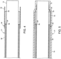
- Fig. 4 shows after the crosslinked polymer sleeve 50 has been positioned to receive a distal segment 36 of composite tube 30 and an entirety of the radiopaque marker 60.
- this geometry suggests that both the radiopaque marker 60 and composite tube 30 inner diameters are matched to be freely slidable on mandrel 14, which may have a uniform diameter corresponding to a 5 or 6 French, for example.
- the outer diameters of composite tube 30 and radiopaque marker 60 are free sliding matches with the preshrunk crosslinked polymer tube 50, which is longer than the radiopaque marker 60.
- a distal portion of the crosslinked polymer sleeve 50 extends unsupported beyond a distal end 64 of the radiopaque marker 60.
- FIG. 5 shows the work-in-progress sheath 21 after a peel away tube 70, such as a fluorinated ethylene propylene heat shrink tube, has been heat shrunk down over the entire tip 25.
- a peel away tube 70 such as a fluorinated ethylene propylene heat shrink tube
- the assembly may be placed in a bonder and heated to a required temperature and duration that causes both the outer thermoplastic tube 35 and loaded polymer radiopaque marker 60 to flow so that the shrinkage forces of crosslinked polymer sleeve 50 and peel away tube 70 produce a flush transition 47 from an outer surface 52 of sleeve 50 to an outer surface 37 of composite tube 30, and squeeze sleeve 50 and radiopaque marker 60 to produce tapered segment 61 in mold contact with inner surface 56 of tapered segment 54.
- crosslinked polymer sleeve 50 has a higher melting temperature than both outer thermoplastic tube 35 and loaded polymer radiopaque marker 60.
- Work-in-progress introducer sheath 21 includes a segment 58 with five layers that include portions of the inner polymer tube 34, the braid 33, the outer thermoplastic tube 35, the crosslinked polymer sleeve 50 and the peel away tube 70.
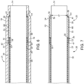
- Fig. 7 shows the completed tip 25 of the introducer sheath 20 after removal of peel away tube 70 and the trimming away of excess crosslinked polymer sleeve 50, if any.
- the crosslinked polymer sleeve 50 has some residual elastic hoop stress, especially at its distal end segment 26, so that it has a rest diameter 17 that is smaller than the outer diameter 16 of the dilator 15 where the tip 25 contacts the dilator in the first configuration 11 to provide a tight interface therebetween.
- the rest diameter may define the diameter of an element at rest, for example when not subject to any deforming force.
- FIG. 9 is similar to Fig. 4 showing after the peel away tube 70 has been heat shrunk down onto the assembly.
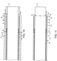
- Fig. 10 shows after the assembly might be placed in a bonding machine at a required time and temperature to flow the outer thermoplastic tube 35 and the radiopaque marker 60 responsive to radial shrinkage of both the crosslinked polymer sleeve 50 and the peel away tube 70.
- peel way tube 70 applies a molding force to produce a flush transition 47 between the outer surface 52 of crosslinked polymer sleeve 50 and the outer surface 37 of the outer thermoplastic tube 35.
- the peel away tube 70 is also engineered to produce molding forces to squish some of the radiopaque marker material out to shape a tapered segment 61 and a flush transition 57 between the outer surface 62 of the radiopaque marker and the outer surface 52 of the crosslinked polymer sleeve 50.
- the transformation from work-in-progress introducer sheath 21 to introducer sheath 20 includes cooling and then removal of the peel away tube 70 as per Fig. 11 . Thereafter, mandrel 14 is removed and sheath 20 is mated with an appropriate dilator 15.
- the present disclosure finds general application to medical introducers, especially when there is a likelihood of the introducer having to pass through tight and/or scared tissues.
- a clinician may better visualize with fluoroscopy precisely where the distal opening of the sheath is in the patient's anatomy.
- the tighter interface between the sheath 20 and the dilator 15 provided by the crosslinked polymer sleeve 50 along with the exterior surface transitions and taper down to the inner supporting dilator helps to ensure smooth insertion through skin, as well as atraumatic and smooth tracking through peripheral arteries.
- the flush outer surface transitions also reduce the likelihood of tissue snags when the introducer sheath is withdrawn.
- the crosslinked polymer sleeve 50 helps to prevent braid 33 exposure during bonding of the tip 25 while reinforcing tip bond strength.
- the crosslinked polymer sleeve 50 may also act as a protective layer to protect the tungsten loading against UV induced oxidation and embrittlement, and may even impart additional protection when the tip 25 contacts calcified tissue.
- the close and preferably elastic fit to the support dilator should significantly reduce insertion forces.
Landscapes
- Health & Medical Sciences (AREA)
- Life Sciences & Earth Sciences (AREA)
- Biophysics (AREA)
- Pulmonology (AREA)
- Engineering & Computer Science (AREA)
- Anesthesiology (AREA)
- Biomedical Technology (AREA)
- Heart & Thoracic Surgery (AREA)
- Hematology (AREA)
- Animal Behavior & Ethology (AREA)
- General Health & Medical Sciences (AREA)
- Public Health (AREA)
- Veterinary Medicine (AREA)
- Media Introduction/Drainage Providing Device (AREA)
Abstract
Description
- The present disclosure relates generally to medical introducers, and more particularly to introducer sheath tip structures.
- Physicians know that advancing introducers through tight and/or scared tissue can be challenging due to the exposure of the sheath distal tip to engagement with surrounding tissue. The introducer sheath includes a distal taper contour from an outer diameter of the introducer sheath down to the outer diameter of the supporting dilator. Variations in tip geometry and any gap between the tip and the dilator can lead to undesirable so called "toe nailing", where the tip digs into tissue at a tip edge or gap. Other less-than-tight interface to the supporting dilator can also be problematic. Apart from this issue, there remains room for improving the positioning of radiopaque markers relative to the distal tip end of introducer sheaths to improve precise positioning in a patient's anatomy. Also, radiopaque markers for introducer sheaths, especially when presented in the form of a loaded thermoplastic, can be at risk for oxidation, and maybe even induced embrittlement.
- The present disclosure is directed to one or more of the problems set forth above.
- An introducer sheath includes a composite tube that extends between a valve and a tip, and includes a braid with a hollow cylindrical shape sandwiched between an inner polymer tube and an outer thermoplastic tube. The tip includes a loaded thermoplastic radiopaque marker at least partially covered by a crosslinked polymer sleeve that receives a distal segment of the composite tube. An outer surface of the proximal end of the crosslinked polymer sleeve has a flush transition to an outer surface of the composite tube, and a distal portion of the crosslinked polymer sleeve extends distally beyond a distal end of the inner polymer tube. The radiopaque marker has a tapered segment distal to the flush transition.
- In another aspect, an introducer includes the introducer sheath and a dilator with a first configuration in which the dilator is received in the introducer sheath, and a second configuration in which the dilator is out of contact with the introducer sheath.
- In still another aspect, a work-in-progress introducer sheath includes a peel away tube that covers a distal segment of the composite tube, the crosslinked polymer sleeve and the flush transition between the outer surfaces of the composite tube and crosslinked sleeve.
-
-
Fig. 1 is an elevational view of medical introducer according to the present disclosure; -
Fig. 2 is a schematic view of a distal end of a work-in-progress introducer sheath supported by a mandrel; -
Fig. 3 is a schematic view showing a loaded polymer radiopaque marker abutting a distal end of a composite tube for the work-in-progress introducer sheath; -
Fig. 4 a crosslinked polymer sleeve slid over the radiopaque marker and a distal end segment of the composite tube; -
Fig. 5 is a schematic view showing a heat shrink tube shrunk down to cover the crosslinked polymer sleeve and a distal segment of the composite tube; -
Fig. 6 is a schematic view showing the work-in-progress introducer sheath after heating to a required time and temperature reshapes the outer thermoplastic tube, the crosslinked polymer sleeve and the loaded plastic radiopaque marker; -
Fig. 7 is a schematic view showing the introducer sheath after the heat shrink tube has been torn away from the work-in-progress introducer sheath, and any excess crosslinked polymer tube is trimmed away and before being mated with a dilator; -
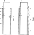
Fig. 8 is a schematic view showing an alternative next step fromFig. 3 , with the distal ends of the crosslinked sleeve and radiopaque marker coincide; -
Fig. 9 is a schematic view showing a heat shrink tube shrunk down to cover the crosslinked polymer sleeve and a distal segment of the composite tube; -
Fig. 10 is a schematic view showing the work-in-progress introducer sheath after heating to a required time and temperature reshapes the outer thermoplastic tube, the crosslinked polymer sleeve and the loaded plastic radiopaque marker; and -
Fig. 11 is a schematic view showing the introducer sheath after the heat shrink tube has been torn away from the work-in-progress introducer sheath and before being mated with a dilator. - Referring initially to
Fig. 1 , anintroducer 10 includes asheath 20 and adilator 15 that can have afirst configuration 11, as shown, in which thedilator 15 is received in thesheath 20, and a second configuration in which thedilator 15 is out of contact with thesheath 20. Those skilled in the art will recognize that the second configuration can occur during manufacture or after theintroducer 10 has been properly positioned in a patient's anatomy. Thesheath 20 includes acomposite tube 30 extending between avalve 32 and atip 25. Thecomposite tube 30 includes abraid 33 with a hollow cylindrical shape sandwiched between, and in contact with, aninner polymer tube 34 and an outerthermoplastic tube 35. In one example, theinner polymer tube 34 might be a thermoset plastic, such as PTFE. As used in this disclosure, and as is typical in the art, a thermoset plastic is different from a thermoplastic. The latter being plastically deformable with heat and pressure, whereas the former is not plastically deformable in the presence of the same heat and pressure. Thebraid 33 may be steel and have a structure well known in the art, but in the context of the present disclosure, a braid is not a coil, which may have less dimensional stability in the present context. In one example, the outer thermoplastic tube may comprise a polyether block amide such as nylon. The composite tube found in COOKO Flexor® Introducer sets is compatible with the teachings of the present disclosure, and need not be taught again here. - Referring now in addition to the two embodiments shown in
Figs. 7 and11 , respectively, which share feature numbering for similar features. In both embodiments, thetip 25 of thesheath 20 includes aradiopaque marker 60 and acrosslinked polymer sleeve 50, both of which are not parts of thecomposite tube 30. Theradiopaque marker 60 is a loaded thermoplastic, such as a soft tungsten loaded (e.g., 65-80% wt. Tu) polyether block amide material formed initially in a hollow cylindrical shape with a length of maybe three millimeters, for example. Thecrosslinked polymer sleeve 50 preferably has a pre-shrunk inner diameter sized to slide over a distal segment of thecomposite tube 30 and theradiopaque marker 60, and a wall thickness preferably less than a wall thickness of thecomposite tube 30. In one example,crosslinked polymer sleeve 50 might be a polyether block amide heat shrink tube of the type manufactured by Cobalt Polymers. Anouter surface 52 at aproximal end 53 of thecrosslinked polymer sleeve 50 has aflush transition 47 to anouter surface 37 of thecomposite tube 30, and adistal portion 55 of thecrosslinked polymer sleeve 50 extends distally beyond adistal end 38 of theinner polymer tube 34. Theradiopaque marker 60 is shaped to include atapered segment 61 distal to theflush transition 47. In the embodiment ofFig. 7 , thetapered segment 61 of theradiopaque marker 60 is in mold contact with aninner surface 56 of atapered segment 54 of thecrosslinked polymer sleeve 50. In theFig. 7 embodiment, adistal end segment 26 of thetip 25 includes exactly one layer, which is a portion of thecrosslinked polymer sleeve 50. In theFig. 11 embodiment thetapered segment 24 oftip 25 includes thetapered segment 61 ofradiopaque marker 60, which comprises the only layer of thedistal end segment 26 of thetip 25. Also in theFig. 11 embodiment, thecrosslinked polymer sleeve 50 may retain a regular cylindrical shape without a taper and stop short of thedistal end segment 26. It is also worth noting that in theFig. 11 embodiment, anouter surface 62 of theradiopaque marker 60 may have aflush transition 57 to theouter surface 52 of thecrosslinked polymer sleeve 50. In both embodiments, theradiopaque marker 60 abuts both adistal end 38 of theinner polymer tube 34 and adistal end 39 of thebraid 33 so that radiopaque marker is positioned distally of both. - Referring now to
Figs. 2-7 , example steps for transforming a work-in-progress introducersheath 21 into anintroducer sheath 20 inform the thermal properties and geometry of various components discussed above. For example,Fig. 2 shows a work-in-progress introducersheath 21 supported on amandrel 14 that has an outer diameter that corresponds to theouter diameter 16 of the dilator 15 (Fig. 1 ). A loadedpolymer radiopaque marker 60, which may be about 3mm in length, is being slid onmandrel 14 toward an exposeddistal end 42 ofcomposite tube 30. InFig. 3 , Aproximal end 63 of theradiopaque marker 60 abutsdistal end 42 supported onmandrel 14.Fig. 4 shows after thecrosslinked polymer sleeve 50 has been positioned to receive adistal segment 36 ofcomposite tube 30 and an entirety of theradiopaque marker 60. Before the application of any heat, this geometry suggests that both theradiopaque marker 60 andcomposite tube 30 inner diameters are matched to be freely slidable onmandrel 14, which may have a uniform diameter corresponding to a 5 or 6 French, for example. The outer diameters ofcomposite tube 30 andradiopaque marker 60 are free sliding matches with the preshrunkcrosslinked polymer tube 50, which is longer than theradiopaque marker 60. A distal portion of thecrosslinked polymer sleeve 50 extends unsupported beyond adistal end 64 of theradiopaque marker 60.Fig. 5 shows the work-in-progress sheath 21 after apeel away tube 70, such as a fluorinated ethylene propylene heat shrink tube, has been heat shrunk down over theentire tip 25. At this point, the heat applied may be insufficient to cause outerthermoplastic tube 35 or loadedpolymer radiopaque marker 60 to run or plastically deform. This deformation is responsive to heat and the molding forces produced by the radial shrinkage ofcrosslinked polymer sleeve 50 and shrinkage of peel awaytube 70. Next, as shown inFig. 6 , the assembly may be placed in a bonder and heated to a required temperature and duration that causes both theouter thermoplastic tube 35 and loaded polymerradiopaque marker 60 to flow so that the shrinkage forces ofcrosslinked polymer sleeve 50 and peel awaytube 70 produce aflush transition 47 from anouter surface 52 ofsleeve 50 to anouter surface 37 ofcomposite tube 30, and squeezesleeve 50 andradiopaque marker 60 to produce taperedsegment 61 in mold contact withinner surface 56 of taperedsegment 54. Preferably,crosslinked polymer sleeve 50 has a higher melting temperature than both outerthermoplastic tube 35 and loaded polymerradiopaque marker 60. Work-in-progress introducer sheath 21 includes asegment 58 with five layers that include portions of theinner polymer tube 34, thebraid 33, theouter thermoplastic tube 35, thecrosslinked polymer sleeve 50 and the peel awaytube 70.Fig. 7 shows the completedtip 25 of theintroducer sheath 20 after removal of peel awaytube 70 and the trimming away of excesscrosslinked polymer sleeve 50, if any. - Preferably, after cooling and removal of
mandrel 14, thecrosslinked polymer sleeve 50 has some residual elastic hoop stress, especially at itsdistal end segment 26, so that it has a rest diameter 17 that is smaller than theouter diameter 16 of thedilator 15 where thetip 25 contacts the dilator in thefirst configuration 11 to provide a tight interface therebetween. It will be appreciated in the context of the present disclosure that the rest diameter may define the diameter of an element at rest, for example when not subject to any deforming force. By choosing a material forcrosslinked polymer sleeve 50 that is visually opaque, any portions of the distal braid that might emerge through theouter thermoplastic tube 35 are covered. - Referring now to
Figs. 2, 3 and8-11 , A slightly different embodiment is created by starting with thedistal end 59 of thecrosslinked polymer sleeve 50 coinciding with thedistal end 64 of theradiopaque marker 60 as shown inFig. 8 , as opposed to the overhanging geometry ofFig.3 .Fig. 9 is similar toFig. 4 showing after the peel awaytube 70 has been heat shrunk down onto the assembly.Fig. 10 shows after the assembly might be placed in a bonding machine at a required time and temperature to flow theouter thermoplastic tube 35 and theradiopaque marker 60 responsive to radial shrinkage of both thecrosslinked polymer sleeve 50 and the peel awaytube 70. In the first instance, peelway tube 70 applies a molding force to produce aflush transition 47 between theouter surface 52 ofcrosslinked polymer sleeve 50 and theouter surface 37 of theouter thermoplastic tube 35. The peel awaytube 70 is also engineered to produce molding forces to squish some of the radiopaque marker material out to shape atapered segment 61 and aflush transition 57 between theouter surface 62 of the radiopaque marker and theouter surface 52 of thecrosslinked polymer sleeve 50. The transformation from work-in-progress introducer sheath 21 tointroducer sheath 20 includes cooling and then removal of the peel awaytube 70 as perFig. 11 . Thereafter,mandrel 14 is removed andsheath 20 is mated with anappropriate dilator 15. - The present disclosure finds general application to medical introducers, especially when there is a likelihood of the introducer having to pass through tight and/or scared tissues. By positioning the radiopaque marker at the distal tip of the sheath, a clinician may better visualize with fluoroscopy precisely where the distal opening of the sheath is in the patient's anatomy. The tighter interface between the
sheath 20 and thedilator 15 provided by thecrosslinked polymer sleeve 50 along with the exterior surface transitions and taper down to the inner supporting dilator helps to ensure smooth insertion through skin, as well as atraumatic and smooth tracking through peripheral arteries. The flush outer surface transitions also reduce the likelihood of tissue snags when the introducer sheath is withdrawn. Usage of thecrosslinked polymer sleeve 50 helps to preventbraid 33 exposure during bonding of thetip 25 while reinforcing tip bond strength. Thecrosslinked polymer sleeve 50 may also act as a protective layer to protect the tungsten loading against UV induced oxidation and embrittlement, and may even impart additional protection when thetip 25 contacts calcified tissue. Finally, the close and preferably elastic fit to the support dilator should significantly reduce insertion forces. -
- 10. introducer
- 11. first configuration
- 12. second configuration
- 14. mandrel
- 15. dilator
- 16. outer diameter
- 20. introducer sheath
- 21. work-in-progress sheath
- 24. tapered segment
- 25. tip
- 26. distal end segment
- 27. rest inner diameter
- 30. composite tube
- 31. proximal end
- 32. valve
- 33. braid
- 34. inner polymer tube
- 35. outer thermoplastic tube
- 36. distal segment
- 37. outer surface
- 38. distal end
- 39. distal end
- 42. distal end
- 47. flush transition
- 50. crosslinked polymer sleeve
- 52. outer surface
- 53. proximal end
- 54. tapered segment
- 55. distal portion
- 56. inner surface
- 57 flush transition
- 58. segment
- 59. distal end
- 60. radiopaque marker
- 61. tapered segment
- 62. outer surface
- 63. proximal end
- 64. distal end
- 70. peel away tube
- The present disclosure further includes the following numbered clauses:
- 1. An introducer comprising:
- a sheath and a dilator having a first configuration in which the dilator is received in the sheath, and a second configuration in which the dilator is out of contact with the sheath;
- the sheath including a composite tube extending between a valve and a tip, and the composite tube includes a braid with a hollow cylindrical shape sandwiched between, and in contact with, an inner polymer tube and an outer thermoplastic tube;
- the tip including a radiopaque marker, which is a loaded thermoplastic, and a crosslinked polymer sleeve that receives a distal segment of the composite tube and at least partially receives the radiopaque marker;
- an outer surface of the crosslinked polymer sleeve has a flush transition to an outer surface of the composite tube at a proximal end of the crosslinked polymer sleeve, and a distal portion of the crosslinked polymer sleeve extends distally beyond a distal end of the inner polymer tube; and
- the radiopaque marker having a tapered segment distal to the flush transition.
- 2. The introducer of clause 1 wherein radiopaque marker abuts a distal end of the braid.
- 3. The introducer of clause 1 wherein the radiopaque marker abuts the distal end of the inner polymer tube.
- 4. The introducer of clause 1 wherein the tapered segment of the radiopaque marker is in contact with a tapered segment of the crosslinked polymer sleeve.
- 5. The introducer of clause 1 wherein the tip has a rest inner diameter that is smaller than an outer diameter of the dilator where the tip contacts the dilator in the first configuration.
- 6. The introducer of clause 1 wherein the crosslinked polymer sleeve is opaque.
- 7. The introducer of clause 1 wherein a distal end segment of the tip includes exactly one layer, which is a portion of the crosslinked polymer sleeve.
- 8. The introducer of clause 1 wherein the radiopaque marker is positioned distally of a distal end of the polymer tube;
- the radiopaque marker has a tapered segment in contact with the tapered segment of the crosslinked polymer sleeve; and
- the radiopaque marker is a tungsten loaded material.
- 9. An introducer sheath comprising:
- a composite tube extending between a valve and a tip, and the composite tube includes a braid with a hollow cylindrical shape sandwiched between, and in contact with, an inner polymer tube and an outer thermoplastic tube;
- the tip including a radiopaque marker, which is a loaded thermoplastic, and a crosslinked polymer sleeve that receives a distal segment of the composite tube and at least partially receives the radiopaque marker;
- an outer surface of the crosslinked polymer sleeve has a flush transition to an outer surface of the composite tube at a proximal end of the crosslinked polymer sleeve, and a distal portion of the crosslinked polymer sleeve extends distally beyond a distal end of the inner polymer tube; and
- the radiopaque marker having a tapered segment distal to the flush transition.
- 10. The introducer sheath of clause 9 wherein the radiopaque marker is entirely positioned distally of a distal end of the inner polymer tube.
- 11. The introducer sheath of
clause 10 wherein the radiopaque marker abuts a distal end of the inner polymer tube. - 12. The introducer sheath of
clause 11 wherein the radiopaque marker is a tungsten loaded material. - 13. The introducer sheath of clause 9 wherein the tapered segment of the radiopaque marker is in mold contact with an inner surface of a tapered segment of the crosslinked polymer sleeve.
- 14. The introducer sheath of clause 13 wherein a distal end segment of the tip includes exactly one layer, which is a portion of the crosslinked polymer sleeve.
- 15. The introducer sheath of
clause 14 wherein the crosslinked polymer sleeve is opaque. - 16. The introducer sheath of clause 9 wherein the tip has a rest inner diameter that is smaller than an inner diameter of the inner polymer tube.
- 17. The introducer sheath of
clause 16 wherein the radiopaque marker is positioned distally of a distal end of the inner polymer tube. - 18. The introducer sheath of clause 17 wherein the tapered segment of the radiopaque marker is in contact with an inner surface of a tapered segment of the crosslinked polymer sleeve.
- 19. A work-in-progress introducer sheath comprising:
- a composite tube extending between a proximal end and a tip, and the composite tube includes a braid with a hollow cylindrical shape sandwiched between, and in contact with, an inner polymer tube and an outer thermoplastic tube;
- the tip including a radiopaque marker, which is a loaded thermoplastic, and a crosslinked polymer sleeve that receives a distal segment of the composite tube and at least partially receives the radiopaque marker;
- an outer surface of the crosslinked polymer sleeve has a flush transition to an outer surface of the composite tube at a proximal end, and the radiopaque marker having a tapered segment distal to the flush transition;
- a peel away tube covering, and in contact with, a distal segment of the composite tube, the flush transition, and the crosslinked polymer sleeve; and
- a distal portion of the crosslinked polymer sleeve extends distally beyond a distal end of the inner polymer tube.
- 20. The work-in-progress introducer sheath of clause 19 wherein the tip includes a segment with five layers that includes a portion of the inner polymer tube, a portion of the braid, a portion of the thermoplastic tube, a portion of the crosslinked polymer sleeve and a portion of the peel away tube.
- Those skilled in the art will recognize that many variations from the example embodiments described above could be made with departing from the scope of the claims set forth below.
Claims (15)
- An introducer comprising:a sheath and a dilator having a first configuration in which the dilator is received in the sheath, and a second configuration in which the dilator is out of contact with the sheath;the sheath including a composite tube extending between a valve and a tip, and the composite tube includes a braid with a hollow cylindrical shape sandwiched between, and in contact with, an inner polymer tube and an outer thermoplastic tube;the tip including a radiopaque marker, which is a loaded thermoplastic, and a crosslinked polymer sleeve that receives a distal segment of the composite tube and at least partially receives the radiopaque marker;an outer surface of the crosslinked polymer sleeve has a flush transition to an outer surface of the composite tube at a proximal end of the crosslinked polymer sleeve, and a distal portion of the crosslinked polymer sleeve extends distally beyond a distal end of the inner polymer tube; andthe radiopaque marker having a tapered segment distal to the flush transition.
- The introducer of claim 1 wherein radiopaque marker abuts a distal end of the braid.
- The introducer of any preceding claim wherein the radiopaque marker abuts the distal end of the inner polymer tube.
- The introducer of any preceding claim wherein the tip has a rest inner diameter that is smaller than an outer diameter of the dilator where the tip contacts the dilator in the first configuration.
- The introducer of any preceding claim wherein the radiopaque marker is positioned distally of a distal end of the polymer tube;the radiopaque marker has a tapered segment in contact with the tapered segment of the crosslinked polymer sleeve; andthe radiopaque marker is a tungsten loaded material.
- An introducer sheath comprising:a composite tube extending between a valve and a tip, and the composite tube includes a braid with a hollow cylindrical shape sandwiched between, and in contact with, an inner polymer tube and an outer thermoplastic tube;the tip including a radiopaque marker, which is a loaded thermoplastic, and a crosslinked polymer sleeve that receives a distal segment of the composite tube and at least partially receives the radiopaque marker;an outer surface of the crosslinked polymer sleeve has a flush transition to an outer surface of the composite tube at a proximal end of the crosslinked polymer sleeve, and a distal portion of the crosslinked polymer sleeve extends distally beyond a distal end of the inner polymer tube; andthe radiopaque marker having a tapered segment distal to the flush transition.
- The introducer sheath of claim 5 wherein the radiopaque marker abuts a distal end of the inner polymer tube.
- The introducer sheath of claim 5 or 6 wherein the radiopaque marker is a tungsten loaded material.
- The introducer of any of claims 1 to 5 or the introducer sheath of any of claims 6 to 8 wherein a distal end segment of the tip includes exactly one layer, which is a portion of the crosslinked polymer sleeve.
- The introducer of any of claims 1 to 5 or the introducer sheath of any of claims 6 to 9 wherein the crosslinked polymer sleeve is opaque.
- The introducer sheath of any of claims 6 to 10 wherein the tip has a rest inner diameter that is smaller than an inner diameter of the inner polymer tube.
- The introducer sheath of any of claims 6 to 11 wherein the radiopaque marker is positioned distally of a distal end of the inner polymer tube, for example wherein the radiopaque marker is entirely positioned distally of a distal end of the inner polymer tube.
- The introducer sheath of any of claims 6 to 12 wherein the tapered segment of the radiopaque marker is in contact with a tapered segment of the crosslinked polymer sleeve.
- A work-in-progress introducer sheath comprising:a composite tube extending between a proximal end and a tip, and the composite tube includes a braid with a hollow cylindrical shape sandwiched between, and in contact with, an inner polymer tube and an outer thermoplastic tube;the tip including a radiopaque marker, which is a loaded thermoplastic, and a crosslinked polymer sleeve that receives a distal segment of the composite tube and at least partially receives the radiopaque marker;an outer surface of the crosslinked polymer sleeve has a flush transition to an outer surface of the composite tube at a proximal end, and the radiopaque marker having a tapered segment distal to the flush transition;a peel away tube covering, and in contact with, a distal segment of the composite tube, the flush transition, and the crosslinked polymer sleeve; anda distal portion of the crosslinked polymer sleeve extends distally beyond a distal end of the inner polymer tube.
- The work-in-progress introducer sheath of claim 14 wherein the tip includes a segment with five layers that includes a portion of the inner polymer tube, a portion of the braid, a portion of the thermoplastic tube, a portion of the crosslinked polymer sleeve and a portion of the peel away tube.
Applications Claiming Priority (1)
| Application Number | Priority Date | Filing Date | Title |
|---|---|---|---|
| US202263399299P | 2022-08-19 | 2022-08-19 |
Publications (1)
| Publication Number | Publication Date |
|---|---|
| EP4335478A1 true EP4335478A1 (en) | 2024-03-13 |
Family
ID=87760531
Family Applications (1)
| Application Number | Title | Priority Date | Filing Date |
|---|---|---|---|
| EP23192267.5A Pending EP4335478A1 (en) | 2022-08-19 | 2023-08-18 | Medical introducer and sheath |
Country Status (2)
| Country | Link |
|---|---|
| US (1) | US12691255B2 (en) |
| EP (1) | EP4335478A1 (en) |
Citations (3)
| Publication number | Priority date | Publication date | Assignee | Title |
|---|---|---|---|---|
| EP1062965A1 (en) * | 1999-06-24 | 2000-12-27 | Medtronic, Inc. | Guiding catheter with radiopaque band |
| US20060095050A1 (en) * | 2004-09-14 | 2006-05-04 | William A. Cook Australia Pty. Ltd. | Large diameter sheath |
| WO2011123222A1 (en) * | 2010-04-01 | 2011-10-06 | Cook Medical Technologies Llc | Tapered sheath |
Family Cites Families (32)
| Publication number | Priority date | Publication date | Assignee | Title |
|---|---|---|---|---|
| US5380304A (en) | 1991-08-07 | 1995-01-10 | Cook Incorporated | Flexible, kink-resistant, introducer sheath and method of manufacture |
| WO1999006099A2 (en) | 1997-07-30 | 1999-02-11 | Cook Incorporated | Medical fluid flow control valve |
| JP5030358B2 (en) | 2000-03-23 | 2012-09-19 | クック メディカル テクノロジーズ エルエルシー | Introducing sheath |
| US20020156459A1 (en) | 2001-04-20 | 2002-10-24 | Scimed Life Systems, Inc | Microcatheter with improved distal tip and transitions |
| ATE406933T1 (en) | 2003-04-25 | 2008-09-15 | Cook Inc | DELIVERY CATHETER |
| DE602004010104T2 (en) * | 2003-04-28 | 2008-09-11 | Cook Inc., Bloomington | FLEXIBLE INTAKE SLIDE WITH DIFFERENT DUROMETER |
| ATE427131T1 (en) * | 2003-06-10 | 2009-04-15 | Lumend Inc | CATHETER SYSTEM AND METHOD FOR OPENING BLOOD VESSEL OCCLUSIONS |
| US8535293B2 (en) * | 2004-04-13 | 2013-09-17 | Gyrus Acmi, Inc. | Atraumatic ureteral access sheath |
| US8235968B2 (en) * | 2004-04-13 | 2012-08-07 | Gyrus Acmi, Inc. | Atraumatic ureteral access sheath |
| US8152767B2 (en) | 2005-05-27 | 2012-04-10 | Cook Medical Technologies Llc | Low profile introducer apparatus |
| US20080091169A1 (en) | 2006-05-16 | 2008-04-17 | Wayne Heideman | Steerable catheter using flat pull wires and having torque transfer layer made of braided flat wires |
| US20080108974A1 (en) * | 2006-10-20 | 2008-05-08 | Vital Signs, Inc. | Reinforced catheter with radiopaque distal tip and process of manufacture |
| US7549975B2 (en) | 2007-04-20 | 2009-06-23 | Abbott Cardiovascular Systems, Inc. | Catheter having a readily bondable multilayer soft tip |
| US8206373B2 (en) | 2008-07-01 | 2012-06-26 | Boston Scientific Scimed, Inc. | Medical device including braid with coated portion |
| US8535294B2 (en) * | 2011-06-01 | 2013-09-17 | Fischell Innovations Llc | Carotid sheath with flexible distal section |
| US9554904B2 (en) | 2011-09-28 | 2017-01-31 | Medtronic CV Luxembourg S.a.r.l. | Distal tip assembly for a heart valve delivery catheter |
| US8671817B1 (en) | 2012-11-28 | 2014-03-18 | Hansen Medical, Inc. | Braiding device for catheter having acuately varying pullwires |
| EP2934656B1 (en) * | 2012-12-20 | 2019-03-13 | Volcano Corporation | Distal catheter tip formation |
| WO2015042368A2 (en) * | 2013-09-19 | 2015-03-26 | W.L. Gore & Associates, Inc. | Dilator systems and methods |
| US9241699B1 (en) | 2014-09-04 | 2016-01-26 | Silk Road Medical, Inc. | Methods and devices for transcarotid access |
| GB2525031A (en) | 2014-04-10 | 2015-10-14 | Cook Medical Technologies Llc | Introducer assembly and protective sleeve therefor |
| EP3056238B1 (en) * | 2015-02-13 | 2019-08-28 | Asahi Intecc Co., Ltd. | Catheter |
| US10357631B2 (en) * | 2015-05-29 | 2019-07-23 | Covidien Lp | Catheter with tapering outer diameter |
| US10398874B2 (en) | 2015-05-29 | 2019-09-03 | Covidien Lp | Catheter distal tip configuration |
| JP7084324B2 (en) * | 2017-02-10 | 2022-06-14 | テルモ株式会社 | Medical long body and medical long body set |
| AU2018260553A1 (en) * | 2017-04-28 | 2019-11-14 | Merit Medical Systems, Inc. | Introducer with partially annealed reinforcement element and related systems and methods |
| US20230240694A1 (en) * | 2017-05-04 | 2023-08-03 | Anoxia Medical Inc. | Catheter Assembly for Blood Clots Removal |
| EP3744378A4 (en) * | 2018-01-25 | 2021-10-13 | Asahi Intecc Co., Ltd. | Catheter |
| US10953195B2 (en) * | 2018-06-01 | 2021-03-23 | Covidien Lp | Flexible tip catheter |
| US11285294B2 (en) | 2018-08-17 | 2022-03-29 | Cook Medical Technologies Llc | Introducer with sheath having a withdrawal support wire |
| US20230172658A1 (en) * | 2020-04-09 | 2023-06-08 | Boston Scientific Medical Device Limited | Catheter and perforation system including catheter |
| JP2025183963A (en) * | 2022-10-25 | 2025-12-18 | テルモ株式会社 | catheter |
-
2023
- 2023-07-25 US US18/225,810 patent/US12691255B2/en active Active
- 2023-08-18 EP EP23192267.5A patent/EP4335478A1/en active Pending
Patent Citations (3)
| Publication number | Priority date | Publication date | Assignee | Title |
|---|---|---|---|---|
| EP1062965A1 (en) * | 1999-06-24 | 2000-12-27 | Medtronic, Inc. | Guiding catheter with radiopaque band |
| US20060095050A1 (en) * | 2004-09-14 | 2006-05-04 | William A. Cook Australia Pty. Ltd. | Large diameter sheath |
| WO2011123222A1 (en) * | 2010-04-01 | 2011-10-06 | Cook Medical Technologies Llc | Tapered sheath |
Also Published As
| Publication number | Publication date |
|---|---|
| US20240058582A1 (en) | 2024-02-22 |
| US12691255B2 (en) | 2026-07-28 |
Similar Documents
| Publication | Publication Date | Title |
|---|---|---|
| JP7862495B2 (en) | Peel-away sheath assembly | |
| JP4139026B2 (en) | Flexible tip guide catheter and method of manufacturing the same | |
| US5292311A (en) | Recessed dilator-sheath assembly and method | |
| US7815762B2 (en) | Method of forming an introducer sheath | |
| CA2589130C (en) | Introducer apparatus | |
| EP1620158B1 (en) | Delivery catheter | |
| JP6050045B2 (en) | Coronary catheter | |
| US20070060927A1 (en) | Microtaper needle and method of use | |
| US20170020501A1 (en) | Introducer sheath with braided filament securement mechanism | |
| EP1092449A1 (en) | Catheter and guide wire | |
| EP2407200A1 (en) | Aspiration catheter | |
| US20050182387A1 (en) | Peel-away catheter shaft | |
| JP2001517500A (en) | Catheter with high tension braided wire restraining element and method of making same | |
| US20100030193A1 (en) | Guide catheter and method of making same | |
| JPH02246984A (en) | Expander/sheath assembly and method thereof | |
| WO2011155491A1 (en) | Medical tube, and manufacturing method for same | |
| WO2018092386A1 (en) | Catheter and method for producing catheter | |
| WO2011123222A1 (en) | Tapered sheath | |
| US20160114130A1 (en) | Medical device including a marker element | |
| CN106175988B (en) | One kind is through conduit valve delivery system | |
| WO2018092387A1 (en) | Catheter assembly | |
| CN110234384B (en) | Medical catheter and method for manufacturing medical tube | |
| US20240058582A1 (en) | Medical introducer and sheath | |
| US20140188005A1 (en) | Wire guide and method of making the same | |
| EP2131909A1 (en) | Improved guidewire introducer and shaping tool |
Legal Events
| Date | Code | Title | Description |
|---|---|---|---|
| PUAI | Public reference made under article 153(3) epc to a published international application that has entered the european phase |
Free format text: ORIGINAL CODE: 0009012 |
|
| STAA | Information on the status of an ep patent application or granted ep patent |
Free format text: STATUS: THE APPLICATION HAS BEEN PUBLISHED |
|
| AK | Designated contracting states |
Kind code of ref document: A1 Designated state(s): AL AT BE BG CH CY CZ DE DK EE ES FI FR GB GR HR HU IE IS IT LI LT LU LV MC ME MK MT NL NO PL PT RO RS SE SI SK SM TR |
|
| STAA | Information on the status of an ep patent application or granted ep patent |
Free format text: STATUS: REQUEST FOR EXAMINATION WAS MADE |
|
| 17P | Request for examination filed |
Effective date: 20240514 |
|
| RBV | Designated contracting states (corrected) |
Designated state(s): AL AT BE BG CH CY CZ DE DK EE ES FI FR GB GR HR HU IE IS IT LI LT LU LV MC ME MK MT NL NO PL PT RO RS SE SI SK SM TR |
|
| STAA | Information on the status of an ep patent application or granted ep patent |
Free format text: STATUS: EXAMINATION IS IN PROGRESS |
|
| 17Q | First examination report despatched |
Effective date: 20260416 |