EP2934656B1 - Distal catheter tip formation - Google Patents
Distal catheter tip formation Download PDFInfo
- Publication number
- EP2934656B1 EP2934656B1 EP13864796.1A EP13864796A EP2934656B1 EP 2934656 B1 EP2934656 B1 EP 2934656B1 EP 13864796 A EP13864796 A EP 13864796A EP 2934656 B1 EP2934656 B1 EP 2934656B1
- Authority
- EP
- European Patent Office
- Prior art keywords
- tip
- shrink tube
- distal
- polyether block
- hypotube
- Prior art date
- Legal status (The legal status is an assumption and is not a legal conclusion. Google has not performed a legal analysis and makes no representation as to the accuracy of the status listed.)
- Active
Links
- 230000015572 biosynthetic process Effects 0.000 title 1
- 239000000463 material Substances 0.000 claims description 134
- 238000000034 method Methods 0.000 claims description 30
- 229920002614 Polyether block amide Polymers 0.000 claims description 23
- 238000010438 heat treatment Methods 0.000 claims description 14
- 238000001816 cooling Methods 0.000 claims description 2
- 230000007704 transition Effects 0.000 description 5
- 238000004519 manufacturing process Methods 0.000 description 4
- 230000008569 process Effects 0.000 description 3
- 210000004204 blood vessel Anatomy 0.000 description 2
- 230000004048 modification Effects 0.000 description 2
- 238000012986 modification Methods 0.000 description 2
- 210000003739 neck Anatomy 0.000 description 2
- NDSPKAPRSUGVNE-SREVYHEPSA-N CCN/C(/C)=C\C=C Chemical compound CCN/C(/C)=C\C=C NDSPKAPRSUGVNE-SREVYHEPSA-N 0.000 description 1
- 230000004075 alteration Effects 0.000 description 1
- 210000000748 cardiovascular system Anatomy 0.000 description 1
- 230000008859 change Effects 0.000 description 1
- 239000002131 composite material Substances 0.000 description 1
- 239000012530 fluid Substances 0.000 description 1
- 238000003384 imaging method Methods 0.000 description 1
- 239000002184 metal Substances 0.000 description 1
- 229910001092 metal group alloy Inorganic materials 0.000 description 1
- 230000001737 promoting effect Effects 0.000 description 1
- 230000000717 retained effect Effects 0.000 description 1
- 238000006467 substitution reaction Methods 0.000 description 1
- 230000001225 therapeutic effect Effects 0.000 description 1
- 229920001169 thermoplastic Polymers 0.000 description 1
- 210000005166 vasculature Anatomy 0.000 description 1
Images

Classifications
-
- A—HUMAN NECESSITIES
- A61—MEDICAL OR VETERINARY SCIENCE; HYGIENE
- A61M—DEVICES FOR INTRODUCING MEDIA INTO, OR ONTO, THE BODY; DEVICES FOR TRANSDUCING BODY MEDIA OR FOR TAKING MEDIA FROM THE BODY; DEVICES FOR PRODUCING OR ENDING SLEEP OR STUPOR
- A61M25/00—Catheters; Hollow probes
- A61M25/0009—Making of catheters or other medical or surgical tubes
- A61M25/001—Forming the tip of a catheter, e.g. bevelling process, join or taper
-
- B—PERFORMING OPERATIONS; TRANSPORTING
- B29—WORKING OF PLASTICS; WORKING OF SUBSTANCES IN A PLASTIC STATE IN GENERAL
- B29C—SHAPING OR JOINING OF PLASTICS; SHAPING OF MATERIAL IN A PLASTIC STATE, NOT OTHERWISE PROVIDED FOR; AFTER-TREATMENT OF THE SHAPED PRODUCTS, e.g. REPAIRING
- B29C63/00—Lining or sheathing, i.e. applying preformed layers or sheathings of plastics; Apparatus therefor
- B29C63/38—Lining or sheathing, i.e. applying preformed layers or sheathings of plastics; Apparatus therefor by liberation of internal stresses
- B29C63/42—Lining or sheathing, i.e. applying preformed layers or sheathings of plastics; Apparatus therefor by liberation of internal stresses using tubular layers or sheathings
-
- B—PERFORMING OPERATIONS; TRANSPORTING
- B29—WORKING OF PLASTICS; WORKING OF SUBSTANCES IN A PLASTIC STATE IN GENERAL
- B29C—SHAPING OR JOINING OF PLASTICS; SHAPING OF MATERIAL IN A PLASTIC STATE, NOT OTHERWISE PROVIDED FOR; AFTER-TREATMENT OF THE SHAPED PRODUCTS, e.g. REPAIRING
- B29C65/00—Joining or sealing of preformed parts, e.g. welding of plastics materials; Apparatus therefor
- B29C65/66—Joining or sealing of preformed parts, e.g. welding of plastics materials; Apparatus therefor by liberation of internal stresses, e.g. shrinking of one of the parts to be joined
- B29C65/68—Joining or sealing of preformed parts, e.g. welding of plastics materials; Apparatus therefor by liberation of internal stresses, e.g. shrinking of one of the parts to be joined using auxiliary shrinkable elements
-
- B—PERFORMING OPERATIONS; TRANSPORTING
- B29—WORKING OF PLASTICS; WORKING OF SUBSTANCES IN A PLASTIC STATE IN GENERAL
- B29C—SHAPING OR JOINING OF PLASTICS; SHAPING OF MATERIAL IN A PLASTIC STATE, NOT OTHERWISE PROVIDED FOR; AFTER-TREATMENT OF THE SHAPED PRODUCTS, e.g. REPAIRING
- B29C66/00—General aspects of processes or apparatus for joining preformed parts
- B29C66/01—General aspects dealing with the joint area or with the area to be joined
- B29C66/05—Particular design of joint configurations
- B29C66/10—Particular design of joint configurations particular design of the joint cross-sections
- B29C66/11—Joint cross-sections comprising a single joint-segment, i.e. one of the parts to be joined comprising a single joint-segment in the joint cross-section
- B29C66/112—Single lapped joints
- B29C66/1122—Single lap to lap joints, i.e. overlap joints
-
- B—PERFORMING OPERATIONS; TRANSPORTING
- B29—WORKING OF PLASTICS; WORKING OF SUBSTANCES IN A PLASTIC STATE IN GENERAL
- B29C—SHAPING OR JOINING OF PLASTICS; SHAPING OF MATERIAL IN A PLASTIC STATE, NOT OTHERWISE PROVIDED FOR; AFTER-TREATMENT OF THE SHAPED PRODUCTS, e.g. REPAIRING
- B29C66/00—General aspects of processes or apparatus for joining preformed parts
- B29C66/50—General aspects of joining tubular articles; General aspects of joining long products, i.e. bars or profiled elements; General aspects of joining single elements to tubular articles, hollow articles or bars; General aspects of joining several hollow-preforms to form hollow or tubular articles
- B29C66/51—Joining tubular articles, profiled elements or bars; Joining single elements to tubular articles, hollow articles or bars; Joining several hollow-preforms to form hollow or tubular articles
- B29C66/52—Joining tubular articles, bars or profiled elements
- B29C66/522—Joining tubular articles
- B29C66/5221—Joining tubular articles for forming coaxial connections, i.e. the tubular articles to be joined forming a zero angle relative to each other
-
- B—PERFORMING OPERATIONS; TRANSPORTING
- B29—WORKING OF PLASTICS; WORKING OF SUBSTANCES IN A PLASTIC STATE IN GENERAL
- B29C—SHAPING OR JOINING OF PLASTICS; SHAPING OF MATERIAL IN A PLASTIC STATE, NOT OTHERWISE PROVIDED FOR; AFTER-TREATMENT OF THE SHAPED PRODUCTS, e.g. REPAIRING
- B29C66/00—General aspects of processes or apparatus for joining preformed parts
- B29C66/50—General aspects of joining tubular articles; General aspects of joining long products, i.e. bars or profiled elements; General aspects of joining single elements to tubular articles, hollow articles or bars; General aspects of joining several hollow-preforms to form hollow or tubular articles
- B29C66/63—Internally supporting the article during joining
-
- B—PERFORMING OPERATIONS; TRANSPORTING
- B29—WORKING OF PLASTICS; WORKING OF SUBSTANCES IN A PLASTIC STATE IN GENERAL
- B29C—SHAPING OR JOINING OF PLASTICS; SHAPING OF MATERIAL IN A PLASTIC STATE, NOT OTHERWISE PROVIDED FOR; AFTER-TREATMENT OF THE SHAPED PRODUCTS, e.g. REPAIRING
- B29C66/00—General aspects of processes or apparatus for joining preformed parts
- B29C66/70—General aspects of processes or apparatus for joining preformed parts characterised by the composition, physical properties or the structure of the material of the parts to be joined; Joining with non-plastics material
- B29C66/73—General aspects of processes or apparatus for joining preformed parts characterised by the composition, physical properties or the structure of the material of the parts to be joined; Joining with non-plastics material characterised by the intensive physical properties of the material of the parts to be joined, by the optical properties of the material of the parts to be joined, by the extensive physical properties of the parts to be joined, by the state of the material of the parts to be joined or by the material of the parts to be joined being a thermoplastic or a thermoset
- B29C66/731—General aspects of processes or apparatus for joining preformed parts characterised by the composition, physical properties or the structure of the material of the parts to be joined; Joining with non-plastics material characterised by the intensive physical properties of the material of the parts to be joined, by the optical properties of the material of the parts to be joined, by the extensive physical properties of the parts to be joined, by the state of the material of the parts to be joined or by the material of the parts to be joined being a thermoplastic or a thermoset characterised by the intensive physical properties of the material of the parts to be joined
- B29C66/7315—Mechanical properties
- B29C66/73151—Hardness
- B29C66/73152—Hardness of different hardness, i.e. the hardness of one of the parts to be joined being different from the hardness of the other part
-
- B—PERFORMING OPERATIONS; TRANSPORTING
- B29—WORKING OF PLASTICS; WORKING OF SUBSTANCES IN A PLASTIC STATE IN GENERAL
- B29C—SHAPING OR JOINING OF PLASTICS; SHAPING OF MATERIAL IN A PLASTIC STATE, NOT OTHERWISE PROVIDED FOR; AFTER-TREATMENT OF THE SHAPED PRODUCTS, e.g. REPAIRING
- B29C66/00—General aspects of processes or apparatus for joining preformed parts
- B29C66/70—General aspects of processes or apparatus for joining preformed parts characterised by the composition, physical properties or the structure of the material of the parts to be joined; Joining with non-plastics material
- B29C66/71—General aspects of processes or apparatus for joining preformed parts characterised by the composition, physical properties or the structure of the material of the parts to be joined; Joining with non-plastics material characterised by the composition of the plastics material of the parts to be joined
-
- B—PERFORMING OPERATIONS; TRANSPORTING
- B29—WORKING OF PLASTICS; WORKING OF SUBSTANCES IN A PLASTIC STATE IN GENERAL
- B29C—SHAPING OR JOINING OF PLASTICS; SHAPING OF MATERIAL IN A PLASTIC STATE, NOT OTHERWISE PROVIDED FOR; AFTER-TREATMENT OF THE SHAPED PRODUCTS, e.g. REPAIRING
- B29C66/00—General aspects of processes or apparatus for joining preformed parts
- B29C66/90—Measuring or controlling the joining process
- B29C66/91—Measuring or controlling the joining process by measuring or controlling the temperature, the heat or the thermal flux
- B29C66/912—Measuring or controlling the joining process by measuring or controlling the temperature, the heat or the thermal flux by measuring the temperature, the heat or the thermal flux
- B29C66/9121—Measuring or controlling the joining process by measuring or controlling the temperature, the heat or the thermal flux by measuring the temperature, the heat or the thermal flux by measuring the temperature
- B29C66/91231—Measuring or controlling the joining process by measuring or controlling the temperature, the heat or the thermal flux by measuring the temperature, the heat or the thermal flux by measuring the temperature of the joining tool
-
- B—PERFORMING OPERATIONS; TRANSPORTING
- B29—WORKING OF PLASTICS; WORKING OF SUBSTANCES IN A PLASTIC STATE IN GENERAL
- B29C—SHAPING OR JOINING OF PLASTICS; SHAPING OF MATERIAL IN A PLASTIC STATE, NOT OTHERWISE PROVIDED FOR; AFTER-TREATMENT OF THE SHAPED PRODUCTS, e.g. REPAIRING
- B29C66/00—General aspects of processes or apparatus for joining preformed parts
- B29C66/90—Measuring or controlling the joining process
- B29C66/91—Measuring or controlling the joining process by measuring or controlling the temperature, the heat or the thermal flux
- B29C66/914—Measuring or controlling the joining process by measuring or controlling the temperature, the heat or the thermal flux by controlling or regulating the temperature, the heat or the thermal flux
- B29C66/9141—Measuring or controlling the joining process by measuring or controlling the temperature, the heat or the thermal flux by controlling or regulating the temperature, the heat or the thermal flux by controlling or regulating the temperature
- B29C66/91421—Measuring or controlling the joining process by measuring or controlling the temperature, the heat or the thermal flux by controlling or regulating the temperature, the heat or the thermal flux by controlling or regulating the temperature of the joining tools
-
- B—PERFORMING OPERATIONS; TRANSPORTING
- B29—WORKING OF PLASTICS; WORKING OF SUBSTANCES IN A PLASTIC STATE IN GENERAL
- B29C—SHAPING OR JOINING OF PLASTICS; SHAPING OF MATERIAL IN A PLASTIC STATE, NOT OTHERWISE PROVIDED FOR; AFTER-TREATMENT OF THE SHAPED PRODUCTS, e.g. REPAIRING
- B29C66/00—General aspects of processes or apparatus for joining preformed parts
- B29C66/90—Measuring or controlling the joining process
- B29C66/91—Measuring or controlling the joining process by measuring or controlling the temperature, the heat or the thermal flux
- B29C66/919—Measuring or controlling the joining process by measuring or controlling the temperature, the heat or the thermal flux characterised by specific temperature, heat or thermal flux values or ranges
-
- B—PERFORMING OPERATIONS; TRANSPORTING
- B29—WORKING OF PLASTICS; WORKING OF SUBSTANCES IN A PLASTIC STATE IN GENERAL
- B29C—SHAPING OR JOINING OF PLASTICS; SHAPING OF MATERIAL IN A PLASTIC STATE, NOT OTHERWISE PROVIDED FOR; AFTER-TREATMENT OF THE SHAPED PRODUCTS, e.g. REPAIRING
- B29C66/00—General aspects of processes or apparatus for joining preformed parts
- B29C66/90—Measuring or controlling the joining process
- B29C66/94—Measuring or controlling the joining process by measuring or controlling the time
- B29C66/944—Measuring or controlling the joining process by measuring or controlling the time by controlling or regulating the time
-
- B—PERFORMING OPERATIONS; TRANSPORTING
- B29—WORKING OF PLASTICS; WORKING OF SUBSTANCES IN A PLASTIC STATE IN GENERAL
- B29C—SHAPING OR JOINING OF PLASTICS; SHAPING OF MATERIAL IN A PLASTIC STATE, NOT OTHERWISE PROVIDED FOR; AFTER-TREATMENT OF THE SHAPED PRODUCTS, e.g. REPAIRING
- B29C66/00—General aspects of processes or apparatus for joining preformed parts
- B29C66/90—Measuring or controlling the joining process
- B29C66/94—Measuring or controlling the joining process by measuring or controlling the time
- B29C66/949—Measuring or controlling the joining process by measuring or controlling the time characterised by specific time values or ranges
-
- B—PERFORMING OPERATIONS; TRANSPORTING
- B29—WORKING OF PLASTICS; WORKING OF SUBSTANCES IN A PLASTIC STATE IN GENERAL
- B29K—INDEXING SCHEME ASSOCIATED WITH SUBCLASSES B29B, B29C OR B29D, RELATING TO MOULDING MATERIALS OR TO MATERIALS FOR MOULDS, REINFORCEMENTS, FILLERS OR PREFORMED PARTS, e.g. INSERTS
- B29K2995/00—Properties of moulding materials, reinforcements, fillers, preformed parts or moulds
- B29K2995/0037—Other properties
- B29K2995/007—Hardness
-
- B—PERFORMING OPERATIONS; TRANSPORTING
- B29—WORKING OF PLASTICS; WORKING OF SUBSTANCES IN A PLASTIC STATE IN GENERAL
- B29L—INDEXING SCHEME ASSOCIATED WITH SUBCLASS B29C, RELATING TO PARTICULAR ARTICLES
- B29L2031/00—Other particular articles
- B29L2031/753—Medical equipment; Accessories therefor
- B29L2031/7542—Catheters
Definitions
- the present disclosure relates generally to catheters for navigating through the human vasculature, and in particular, to improved methods of forming a distal tip for a catheter.
- Catheters such as intravascular catheters are well known for use in diagnostic and therapeutic applications wherein it is necessary to administer a fluid to, or otherwise contact, a precise location within the cardiovascular system, for example, by guiding the tip or distal end of the catheter through branching blood vessels. Such guiding is accomplished in part by manipulation of a proximal portion of the catheter in order to impart forces needed to curve and guide the catheter through the curving and branching blood vessels.
- EP1004327 describes a soft tip guiding catheter and method of fabrication.
- distal tips of catheters are made by hand. For example, an operator bonds or necks heated material over a mandrel, cools the material, and trims the material to the desired length. If the material is necked incorrectly, the operator has to reheat the part until the correct shape is achieved. The process takes both time and skill.
- the method includes providing a mandrel and a holding hypotube.
- a tip first material, tip second material, and the holding hypotube are assembled over the mandrel.
- the first material is placed over the mandrel and the hypotube, and the second material is placed over the mandrel and under the first material.
- the first material has an outer diameter than is greater than the outer diameter of the second material.
- a shrink tube of heat-shrink material is then placed around at least a junction of the first and second materials. The shrink tube is heated, the first and second materials cooled, and the shrink tube and hypotube removed.
- the shrink tube, first material, and second material are centered between two heating dies configured to form a circle around the shrink tube, first material, and second material.
- the shrink tube, first material, and second material are heated to a temperature of about 121°C to 260°C (250°F to 500°F).
- the heating time may be between about 0.25 to 60 seconds.
- the methods include placing a first polyether block amide having a first Shore D durometer hardness over the mandrel and the hypotube, and placing a second polyether block amide having a second Shore D hardness that is greater than the first Shore D hardness over the mandrel and under the first polyether block amide.
- the first polyether block amide generally has a Shore D hardness of about 50 to 60, while the second polyether block amide typically has a Shore D hardness of about 60 to 70.
- the first polyether block amide has Shore D hardness of about 55, and the second polyether block amide has a Shore D hardness of about 63.
- the methods include providing a holding hypotube with a distal leg and a distal back.
- the tip first material is placed over the mandrel and the distal leg, and the tip second material is placed over the mandrel and under the first material so that the second material abuts the distal leg.
- the first material has an outer diameter than is greater than the outer diameter of the second material.
- the first material abuts the distal back of the hypotube.
- a catheter is formed including a distal tip formed according to the methods described herein.
- a subassembly 100 for forming a tapering distal tip for a catheter is shown.
- the tip first material 120, tip second material 130 and holding hypotube 140 are assembled over the mandrel 110.
- the mandrel 110 may be a metal tube or other suitable material thin enough to pass through the inner lumens of tip first material 120, tip second material 130, and holding hypotube 140.
- the mandrel 110 is positioned in the inner lumens of the tip first material 120 and tip second material 130 to keep the inner lumens open during the fusing of the tip first and second materials 120, 130.
- the mandrel 110 has a diameter of about 1.07mm (0.042 inches).
- the tip first material 120 and tip second material 130 are any materials suitable for forming a flexible distal tip.
- the tip first and second materials 120, 130 include a polyether block amide, such as Pebax® thermoplastic polymers available from Arkema Inc.
- the flexible materials are inexpensive and create a strong bonding surface that aids in tensile strength.
- the flexible materials also allow the original shape to be retained after going around tortuous paths.
- the materials can be used on the distal section of a catheter to guide the unit during an operation.
- the tip first material 120 has an inner diameter 122 and an outer diameter 124.
- the inner diameter 122 measures about 1.57mm (0.062) inches and the outer diameter 124 measures about 2.54mm (0.100 inches).
- the tip first material 120 includes a polyether block amide having a Shore D durometer hardness of about 50 to 60.
- the tip first material 120 may include Pebax® 55D.
- the tip second material 130 has an inner diameter 132 and an outer diameter 134.
- the inner diameter 132 measures about 1.30mm (0.051 inches) and outer diameter 134 measures about 1.55mm (0.061 inches).
- the tip second material 130 includes a polyether block amide having a Shore D durometer hardness of about 60 to 70.
- the tip second material 130 may include Pebax® 63D.
- the outer diameter 124 of the tip first material 120 is greater than the outer diameter 134 of the tip second material 130. This facilitates the method of the present disclosure by allowing tip second material 130 to slide under or within the tip first material 120.
- FIG. 3 illustrates a holding hypotube 140.
- the holding hypotube 140 includes a proximal portion 148 and a distal portion 146.
- the holding hypotube 140 is a metal alloy tubing that provides support during the manufacturing method.
- the distal portion 146 includes a distal leg 142 and a distal back 144.
- the distal leg 142 protrudes from the distal back 144 in one direction and extends into an inner lumen of the proximal portion 148 in another direction.
- the distal leg 142 is a cylindrical projection with an outer diameter of about 1.50mm (0.059 inches) and an inner diameter of about 1.27mm (0.050 inches).
- the distal leg 142 extends about 1.12mm (0.044 inches) from the distal back 144.
- the distal back 144 is a shoulder extending between an outer diameter of about 2.54mm (0.100 inches) for proximal portion 148 and 1.50mm (0.059 inches) for the outer diameter of the cylindrical projection.
- FIG. 4 illustrates the cross-section of the subassembly 100 of FIG. 1 taken along line 4-4.
- the tip first material 120 is placed over the distal leg 142, and the distal leg 142 is placed over the mandrel 110.
- the dimensions of the tip first material 120, tip second material 130, the distal leg 142, the distal back 144, and the mandrel 110 are chosen so that this arrangement occurs.
- the proximal end 138 of the tip second material 120 is shown as its outer diameter is larger than the outer diameter of the cylindrical projection.
- Between the first tip material 120 and the tip second material 130 is an air gap 128.
- the air gap 128 separates the second tip material 130 and the tip first material 120 by about 0.0254mm (0.001 inches). The air gap 128 eases assembly of the components and is eliminated as the parts melt during the manufacturing process.
- the method of forming a tapering distal tip begins by providing the mandrel 110 and holding hypotube 140.
- the tip first material 120 and the tip second material 130 are cut and placed distally over the mandrel 110 and the holding hypotube 140.
- the tip first material 120 is placed over the mandrel and the distal leg 142 of the holding hypotube 140.
- the tip first material 120 butts up to the distal back 144.
- the tip first material 120 merely touches the edge of the distal back 144, but does not go over the proximal portion 148 of the holding hypotube 140.
- the air gap 128 includes the space between the distal leg 142 and the tip first material 120.
- the tip second material 130 is placed over the mandrel and within the inner lumen of the tip second material 130.
- the tip second material 130 butts up to the distal leg 142 of the hypotube 140.
- the proximal end 138 of the tip second material 130 merely touches the edge of the distal leg 142, but does not go over it.
- the mandrel 110 is removed from FIG. 5 for ease of illustration.
- a shrink tube 150 of heat- shrink material is placed over the junction between the tip first material 120 and the tip second material 130, as well as over the holding hypotube 140. Bonding of the tip first and second materials 120,130 is completed by applying heat to the shrink tube 150 to melt the first and second materials 120, 130, while also shrinking the shrink tube 150.
- the shrink tube 150 may be manufactured from a material that will prevent a permanent adhesion of the shrink tube 150 to the first and second tip materials 120, 130, so that shrink tube 150 can be easily removed (for example, by peeling off) at the end of the bonding process.
- mandrel 110 may be manufactured from or coated with a material that will not adhere to the inner lumen of the first and second tip materials 120, 130.
- heating shrink tube 150 involves centering shrink tube 150, tip first material 120, and tip second material 130 between two heating dies configured to form a
- the top of the dies may be used to pre-shrink the shrink tube 150.
- the shrink tube 150, tip first material 120, and tip second material 130 are heated to between about 121°C to 260°C (250°F to 500°F) for about 0.25 to 60 seconds. Heat is applied by a hot box and verified with thermocouples.
- the time and temperature of the heating machine is automatically controlled so the operator's task is limited to pre-shrinking and placement in the dies. Since the placement in the machine may be controlled by a micrometer, the operator is able to place the shrink tube 150, tip first material 120, and tip second material 130 in the same location every time. Any operator can be trained on these steps, increasing the consistency of the formed tip.
- a button may be pushed that triggers the machine to heat for a specific time. Once the appropriate time and temperature are reached, the dies that are heating the shrink tube 150, tip first material 120, and tip second material 130 can automatically open. The operator then cools the part and removes the shrink tube 150.
- the shrink tube 150 shrinks and constrains a flow of first and second materials 120, 130.
- first and second materials 120, 130 melt, they fuse together to form a composite tip having different thicknesses and material properties.
- the distal most portion of the tip is formed entirely of tip second material 130, making it the most flexible area.
- the proximal portion of the tip is formed entirely of tip first material 120, making it more rigid than the distal portion of tip first material 120.
- the tapering transition zone 125 is formed of both materials and allows a smooth transition in stiffness between the distal and proximal portions.
- shrink tube 150 and holding hypotube 140 are removed to yield a flexible distal tip.
- the inner diameter of the distal tip has been molded during the heating process to match the mandrel 110 outer diameter over most of the length with an enlarged inner diameter matching the outer diameter of the distal leg 142 at the proximal portion.
- distal tip 600 includes tip first material 120 and tip second material 130. As illustrated, distal tip 600 is bonded to an imaging hypotube 160. Shrink tube 150 created a smooth and long transition zone from the tip first material 120 to the tip second material 130 over their junction. The resulting bond is strong and flexible, with a transition zone of blended material properties, rather than an abrupt transition. In an exemplary embodiment, the length of the distal tip 600 is about 12 mm.
- the tip can be made as a sub-assembly, which increases stock and ultimately saves time and money. Also, time and money decrease because the two materials can be ordered in bulk and pre-trimmed.
Description
- The present disclosure relates generally to catheters for navigating through the human vasculature, and in particular, to improved methods of forming a distal tip for a catheter.
- Catheters such as intravascular catheters are well known for use in diagnostic and therapeutic applications wherein it is necessary to administer a fluid to, or otherwise contact, a precise location within the cardiovascular system, for example, by guiding the tip or distal end of the catheter through branching blood vessels. Such guiding is accomplished in part by manipulation of a proximal portion of the catheter in order to impart forces needed to curve and guide the catheter through the curving and branching blood vessels.
-
EP1004327 describes a soft tip guiding catheter and method of fabrication. - Generally, distal tips of catheters are made by hand. For example, an operator bonds or necks heated material over a mandrel, cools the material, and trims the material to the desired length. If the material is necked incorrectly, the operator has to reheat the part until the correct shape is achieved. The process takes both time and skill.
- In addition, consistency of necking between two different operators is difficult to achieve. One operator may neck harder or heat longer than the other. Moreover, the heat being applied may not be transferred consistently between the part and heat torch so that one portion of the part will endure more or less heat.
- Therefore, a need exists for methods of making distal tips for catheters that reduce human error and cost, and increase reproducibility.
- The present disclosure provides various embodiments of methods of forming a tapering distal tip for a catheter. In an exemplary embodiment, the method includes providing a mandrel and a holding hypotube. A tip first material, tip second material, and the holding hypotube are assembled over the mandrel. Specifically, the first material is placed over the mandrel and the hypotube, and the second material is placed over the mandrel and under the first material. The first material has an outer diameter than is greater than the outer diameter of the second material. A shrink tube of heat-shrink material is then placed around at least a junction of the first and second materials. The shrink tube is heated, the first and second materials cooled, and the shrink tube and hypotube removed. In some embodiments, the shrink tube, first material, and second material are centered between two heating dies configured to form a circle around the shrink tube, first material, and second material. In one embodiment, the shrink tube, first material, and second material are heated to a temperature of about 121°C to 260°C (250°F to 500°F). The heating time may be between about 0.25 to 60 seconds. The methods reduce the possibility of human error and increase consistency of the distal tips produced.
- In other embodiments, the methods include placing a first polyether block amide having a first Shore D durometer hardness over the mandrel and the hypotube, and placing a second polyether block amide having a second Shore D hardness that is greater than the first Shore D hardness over the mandrel and under the first polyether block amide. The first polyether block amide generally has a Shore D hardness of about 50 to 60, while the second polyether block amide typically has a Shore D hardness of about 60 to 70. In an exemplary embodiment, the first polyether block amide has Shore D hardness of about 55, and the second polyether block amide has a Shore D hardness of about 63.
- In alternative embodiments, the methods include providing a holding hypotube with a distal leg and a distal back. The tip first material is placed over the mandrel and the distal leg, and the tip second material is placed over the mandrel and under the first material so that the second material abuts the distal leg. The first material has an outer diameter than is greater than the outer diameter of the second material. In one embodiment, the first material abuts the distal back of the hypotube. In a further aspect, a catheter is formed including a distal tip formed according to the methods described herein.
- Both the foregoing general description and the following detailed description are exemplary and explanatory in nature and are intended to provide an understanding of the present disclosure without limiting the scope of the present disclosure. In that regard, additional aspects, features, and advantages of the present disclosure will become apparent to one skilled in the art from the following detailed description.
- Aspects of the present disclosure are best understood from the following detailed description when read with the accompanying figures. It is emphasized that, in accordance with the standard practice in the industry, various features are not drawn to scale. In fact, the dimensions of the various features may be arbitrarily increased or reduced for clarity of discussion. In addition, the present disclosure may repeat reference numerals and/or letters in the various examples. This repetition is for the purpose of simplicity and clarity and does not in itself dictate a relationship between the various embodiments and/or configurations discussed.
-
FIG. 1 illustrates a subassembly of two tip materials to be bonded according to various aspects of the present disclosure. -
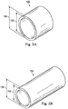
FIGS. 2A and 2B are perspective views of the tip first and second materials, respectively, prior to being bonded. -
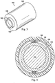
FIG. 3 is a perspective view of a holding hypotube. -
FIG. 4 is a diagrammatic cross-section of the subassembly ofFIG. 1 taken along line 4-4. -
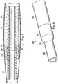
FIG. 5 is a diagrammatic cross-sectional side view of the subassembly ofFIG. 1 .FIG. 6 illustrates a tapered distal tip formed according to various aspects of the present disclosure. - For the purposes of promoting an understanding of the principles of the present disclosure, reference will now be made to the embodiments illustrated in the drawings, and specific language will be used to describe the same. It is nevertheless understood that no limitation to the scope of the disclosure is intended. Any alterations and further modifications to the described devices and methods, and any further application of the principles of the present disclosure are fully contemplated and included within the present disclosure as would normally occur to one skilled in the art to which the disclosure relates. In particular, it is fully contemplated that the features, components, and/or steps described with respect to one embodiment may be combined with the features, components, and/or steps described with respect to other embodiments of the present disclosure. For the sake of brevity, however, the numerous iterations of these combinations will not be described separately.
- Referring to
FIG. 1 , asubassembly 100 for forming a tapering distal tip for a catheter is shown. The tipfirst material 120, tipsecond material 130 and holdinghypotube 140 are assembled over themandrel 110. Themandrel 110 may be a metal tube or other suitable material thin enough to pass through the inner lumens of tipfirst material 120, tipsecond material 130, and holdinghypotube 140. Themandrel 110 is positioned in the inner lumens of the tipfirst material 120 and tipsecond material 130 to keep the inner lumens open during the fusing of the tip first andsecond materials mandrel 110 has a diameter of about 1.07mm (0.042 inches). - The tip
first material 120 and tipsecond material 130 are any materials suitable for forming a flexible distal tip. In an exemplary embodiment, the tip first andsecond materials - Moving now to
FIG. 2 A , the tipfirst material 120 has aninner diameter 122 and anouter diameter 124. In one embodiment, theinner diameter 122 measures about 1.57mm (0.062) inches and theouter diameter 124 measures about 2.54mm (0.100 inches). In another embodiment, the tipfirst material 120 includes a polyether block amide having a Shore D durometer hardness of about 50 to 60. For example, the tipfirst material 120 may include Pebax® 55D. - Turning to
FIG. 2B , the tipsecond material 130 has aninner diameter 132 and anouter diameter 134. In one embodiment, theinner diameter 132 measures about 1.30mm (0.051 inches) andouter diameter 134 measures about 1.55mm (0.061 inches). In another embodiment, the tipsecond material 130 includes a polyether block amide having a Shore D durometer hardness of about 60 to 70. For example, the tipsecond material 130 may include Pebax® 63D. - The
outer diameter 124 of the tipfirst material 120 is greater than theouter diameter 134 of the tipsecond material 130. This facilitates the method of the present disclosure by allowing tipsecond material 130 to slide under or within the tipfirst material 120. -
FIG. 3 illustrates a holdinghypotube 140. The holdinghypotube 140 includes aproximal portion 148 and adistal portion 146. The holdinghypotube 140 is a metal alloy tubing that provides support during the manufacturing method. Thedistal portion 146 includes adistal leg 142 and adistal back 144. Thedistal leg 142 protrudes from the distal back 144 in one direction and extends into an inner lumen of theproximal portion 148 in another direction. In an exemplary embodiment, thedistal leg 142 is a cylindrical projection with an outer diameter of about 1.50mm (0.059 inches) and an inner diameter of about 1.27mm (0.050 inches). In one embodiment, thedistal leg 142 extends about 1.12mm (0.044 inches) from thedistal back 144. In an alternative embodiment, thedistal back 144 is a shoulder extending between an outer diameter of about 2.54mm (0.100 inches) forproximal portion 148 and 1.50mm (0.059 inches) for the outer diameter of the cylindrical projection. -
FIG. 4 illustrates the cross-section of thesubassembly 100 ofFIG. 1 taken along line 4-4. As can be seen, the tipfirst material 120 is placed over thedistal leg 142, and thedistal leg 142 is placed over themandrel 110. The dimensions of the tipfirst material 120, tipsecond material 130, thedistal leg 142, thedistal back 144, and themandrel 110 are chosen so that this arrangement occurs. Theproximal end 138 of the tipsecond material 120 is shown as its outer diameter is larger than the outer diameter of the cylindrical projection. Between thefirst tip material 120 and the tipsecond material 130 is anair gap 128. In an exemplary embodiment, theair gap 128 separates thesecond tip material 130 and the tipfirst material 120 by about 0.0254mm (0.001 inches). Theair gap 128 eases assembly of the components and is eliminated as the parts melt during the manufacturing process. - The method of forming a tapering distal tip will now be described. The method begins by providing the
mandrel 110 and holdinghypotube 140. The tipfirst material 120 and the tipsecond material 130 are cut and placed distally over themandrel 110 and the holdinghypotube 140. - Specifically, referring to
FIG. 5 , the tipfirst material 120 is placed over the mandrel and thedistal leg 142 of the holdinghypotube 140. The tipfirst material 120 butts up to thedistal back 144. The tipfirst material 120 merely touches the edge of thedistal back 144, but does not go over theproximal portion 148 of the holdinghypotube 140. Theair gap 128 includes the space between thedistal leg 142 and the tipfirst material 120. The tipsecond material 130 is placed over the mandrel and within the inner lumen of the tipsecond material 130. The tipsecond material 130 butts up to thedistal leg 142 of thehypotube 140. Since the outer diameter of thedistal leg 142 is greater than the inner diameter of the tipsecond material 130, theproximal end 138 of the tipsecond material 130 merely touches the edge of thedistal leg 142, but does not go over it. Themandrel 110 is removed fromFIG. 5 for ease of illustration. - Next, a
shrink tube 150 of heat- shrink material is placed over the junction between the tipfirst material 120 and the tipsecond material 130, as well as over the holdinghypotube 140. Bonding of the tip first and second materials 120,130 is completed by applying heat to theshrink tube 150 to melt the first andsecond materials shrink tube 150. - The
shrink tube 150 may be manufactured from a material that will prevent a permanent adhesion of theshrink tube 150 to the first andsecond tip materials shrink tube 150 can be easily removed (for example, by peeling off) at the end of the bonding process. Similarly,mandrel 110 may be manufactured from or coated with a material that will not adhere to the inner lumen of the first andsecond tip materials - In one embodiment, heating shrink
tube 150 involves centeringshrink tube 150, tipfirst material 120, and tipsecond material 130 between two heating dies configured to form a - circle around the
shrink tube 150, tipfirst material 120, and tipsecond material 130. The top of the dies may be used to pre-shrink theshrink tube 150. Theshrink tube 150, tipfirst material 120, and tipsecond material 130 are heated to between about 121°C to 260°C (250°F to 500°F) for about 0.25 to 60 seconds. Heat is applied by a hot box and verified with thermocouples. - In an exemplary embodiment, the time and temperature of the heating machine is automatically controlled so the operator's task is limited to pre-shrinking and placement in the dies. Since the placement in the machine may be controlled by a micrometer, the operator is able to place the
shrink tube 150, tipfirst material 120, and tipsecond material 130 in the same location every time. Any operator can be trained on these steps, increasing the consistency of the formed tip. After placement between the dies, a button may be pushed that triggers the machine to heat for a specific time. Once the appropriate time and temperature are reached, the dies that are heating theshrink tube 150, tipfirst material 120, and tipsecond material 130 can automatically open. The operator then cools the part and removes theshrink tube 150. - During heating, the
shrink tube 150 shrinks and constrains a flow of first andsecond materials second materials second material 130, making it the most flexible area. The proximal portion of the tip is formed entirely of tipfirst material 120, making it more rigid than the distal portion of tipfirst material 120. The taperingtransition zone 125 is formed of both materials and allows a smooth transition in stiffness between the distal and proximal portions. After cooling first andsecond materials tube 150 and holding hypotube 140 are removed to yield a flexible distal tip. The inner diameter of the distal tip has been molded during the heating process to match themandrel 110 outer diameter over most of the length with an enlarged inner diameter matching the outer diameter of thedistal leg 142 at the proximal portion. - Referring to
FIG. 6 ,distal tip 600 includes tipfirst material 120 and tipsecond material 130. As illustrated,distal tip 600 is bonded to animaging hypotube 160. Shrinktube 150 created a smooth and long transition zone from the tipfirst material 120 to the tipsecond material 130 over their junction. The resulting bond is strong and flexible, with a transition zone of blended material properties, rather than an abrupt transition. In an exemplary embodiment, the length of thedistal tip 600 is about 12 mm. - The methods described herein are simpler, less expensive, save time, reduce the possibility of human error and improve reproducibility by introducing automated machines. Automated heating devices help control the consistency of the tip, which lowers the scrap ratio. There is no added step for a mis-shaped part, reducing the assembly time. This process can be duplicated by any operator, giving a more lean manufacturing line and improving the consistency.
- The tip can be made as a sub-assembly, which increases stock and ultimately saves time and money. Also, time and money decrease because the two materials can be ordered in bulk and pre-trimmed.
- Persons skilled in the art will recognize that the devices and methods described above can be modified in various ways. Accordingly, persons of ordinary skill in the art will appreciate that the embodiments encompassed by the present disclosure are not limited to the particular exemplary embodiments described above. In that regard, although illustrative embodiments have been shown and described, a wide range of modification, change, and substitution is contemplated in the foregoing disclosure. It is understood that such variations may be made to the foregoing without departing from the scope of the present disclosure.
Claims (13)
- A method of forming a tapering distal tip (600) for a catheter, comprising:providing a mandrel (110) and a holding hypotube (140);placing a tip first material (120) with a first outer diameter (124) over the mandrel and the hypotube;placing a tip second material (130) with a second outer diameter (134) over the mandrel and under the first material, the first outer diameter being greater than the second outer diameter;placing a shrink tube (150) of heat-shrink material around at least a junction of the first material and second material;heating the shrink tube;cooling the first material and second material; andremoving the shrink tube and the hypotube.
- The method of claim 1, wherein the first material comprises a polyether block amide having a Shore D durometer hardness of about 50 to 60 and the second material comprises a polyether block amide having a Shore D durometer hardness of about 60 to 70.
- The method of claim 1, wherein the first material has a Shore D durometer hardness of about 55 and the second material has a Shore D durometer hardness of about 63.
- The method of claim 1, wherein the first material abuts a distal back (144) of the hypotube.
- The method of claim 1, wherein the second material abuts a distal leg (142) of the hypotube.
- The method of claim 1, wherein heating the shrink tube comprises centering the shrink tube, first material, and second material between two heating dies configured to form a circle around the shrink tube, first material, and second material.
- The method of claim 6, wherein the shrink tube, first material, and second material are heated between about 121°C to 260°C (250°F to 500°F).
- The method of claim 7, wherein the shrink tube, first material, and second material are heated for about 0.25 to 60 seconds.
- The method of claim 1, wherein the first material comprises a first polyether block amide having a first Shore D durometer hardness, wherein the second material comprises a second polyether block amide having a second Shore D durometer hardness that is greater than the first Shore D durometer hardness, and wherein heating the shrink tube comprises centering the shrink tube, first material, and second material between two heating dies configured to form a circle around the shrink tube, first material, and second material.
- The method of claim 9, wherein the first polyether block amide abuts a distal back (144) of the hypotube.
- The method of claim 9, wherein the second polyether block amide abuts a distal leg (142) of the hypotube.
- The method of claim 9, wherein the shrink tube, first polyether block amide, and second polyether block amide are heated between about 121°C to 260°C (250°F to 500°F).
- The method of claim 12, wherein the shrink tube, first polyether block amide, and second polyether block amide are heated for about 0.25 to 60 seconds.
Applications Claiming Priority (2)
| Application Number | Priority Date | Filing Date | Title |
|---|---|---|---|
| US201261740403P | 2012-12-20 | 2012-12-20 | |
| PCT/US2013/076184 WO2014100211A1 (en) | 2012-12-20 | 2013-12-18 | Distal catheter tip formation |
Publications (3)
| Publication Number | Publication Date |
|---|---|
| EP2934656A1 EP2934656A1 (en) | 2015-10-28 |
| EP2934656A4 EP2934656A4 (en) | 2016-08-03 |
| EP2934656B1 true EP2934656B1 (en) | 2019-03-13 |
Family
ID=50975495
Family Applications (1)
| Application Number | Title | Priority Date | Filing Date |
|---|---|---|---|
| EP13864796.1A Active EP2934656B1 (en) | 2012-12-20 | 2013-12-18 | Distal catheter tip formation |
Country Status (5)
| Country | Link |
|---|---|
| US (1) | US9149600B2 (en) |
| EP (1) | EP2934656B1 (en) |
| JP (1) | JP6320419B2 (en) |
| CA (1) | CA2895208A1 (en) |
| WO (1) | WO2014100211A1 (en) |
Families Citing this family (5)
| Publication number | Priority date | Publication date | Assignee | Title |
|---|---|---|---|---|
| US10729886B2 (en) | 2016-08-24 | 2020-08-04 | Intuitive Surgical Operations, Inc. | Axial support structure for a flexible elongate device |
| CN110996829B (en) * | 2017-07-21 | 2023-11-21 | 直观外科手术操作公司 | Flexible elongate device system and method |
| EP3446861A1 (en) * | 2017-08-21 | 2019-02-27 | Gambro Lundia AB | Method for sealing medical devices |
| CN111432732A (en) * | 2017-12-07 | 2020-07-17 | 皇家飞利浦有限公司 | Flexible tips for intraluminal imaging devices and related devices, systems, and methods |
| CN111251615B (en) * | 2019-12-25 | 2022-05-24 | 武汉阿格斯科技有限公司 | OCT catheter tip preparation method |
Family Cites Families (12)
| Publication number | Priority date | Publication date | Assignee | Title |
|---|---|---|---|---|
| JPS60126170A (en) * | 1983-12-14 | 1985-07-05 | テルモ株式会社 | Catheter and its production |
| US4636272A (en) * | 1985-02-19 | 1987-01-13 | Cordis Corporation | Process for thermally bonding plastic tubes |
| US4863442A (en) * | 1987-08-14 | 1989-09-05 | C. R. Bard, Inc. | Soft tip catheter |
| US6245053B1 (en) * | 1998-11-09 | 2001-06-12 | Medtronic, Inc. | Soft tip guiding catheter and method of fabrication |
| US6187130B1 (en) * | 1999-05-26 | 2001-02-13 | Scimed Life Systems, Inc. | Method of creating a tip on a catheter |
| US7862541B2 (en) * | 2000-05-22 | 2011-01-04 | Abbott Laboratories Vascular Enterprises Limited | Catheter having a soft distal tip |
| US20030135231A1 (en) * | 2002-01-17 | 2003-07-17 | Goodin Richardf L. | Catheter bond configuration |
| US7322988B2 (en) * | 2003-01-17 | 2008-01-29 | Boston Scientific Scimed, Inc. | Methods of forming catheters with soft distal tips |
| US7261850B2 (en) * | 2004-06-30 | 2007-08-28 | Cordis Corporation | Methods of making balloon catheter tip |
| JP2007029510A (en) * | 2005-07-28 | 2007-02-08 | Kaneka Corp | Medical catheter tube and its manufacturing method |
| US9211389B2 (en) * | 2009-12-07 | 2015-12-15 | Cook Medical Technologies Llc | Offset soft tip with proposed tooling |
| JP5732259B2 (en) * | 2011-01-12 | 2015-06-10 | 株式会社グッドマン | catheter |
-
2013
- 2013-12-18 EP EP13864796.1A patent/EP2934656B1/en active Active
- 2013-12-18 JP JP2015549637A patent/JP6320419B2/en not_active Expired - Fee Related
- 2013-12-18 CA CA2895208A patent/CA2895208A1/en not_active Abandoned
- 2013-12-18 WO PCT/US2013/076184 patent/WO2014100211A1/en active Application Filing
- 2013-12-19 US US14/134,961 patent/US9149600B2/en active Active
Non-Patent Citations (1)
| Title |
|---|
| None * |
Also Published As
| Publication number | Publication date |
|---|---|
| JP2016505324A (en) | 2016-02-25 |
| EP2934656A4 (en) | 2016-08-03 |
| EP2934656A1 (en) | 2015-10-28 |
| US9149600B2 (en) | 2015-10-06 |
| WO2014100211A1 (en) | 2014-06-26 |
| CA2895208A1 (en) | 2014-06-26 |
| US20140180254A1 (en) | 2014-06-26 |
| JP6320419B2 (en) | 2018-05-09 |
Similar Documents
| Publication | Publication Date | Title |
|---|---|---|
| EP2934647B1 (en) | Distal catheter tips and formation thereof | |
| EP2934656B1 (en) | Distal catheter tip formation | |
| US5382234A (en) | Over-the-wire balloon catheter | |
| US8636717B2 (en) | Catheter having improved bonding region | |
| US8057430B2 (en) | Catheter with skived tubular member | |
| JP6248630B2 (en) | Balloon catheter and manufacturing method thereof | |
| JP2004503304A (en) | Method of making a catheter shaft having one or more guidewire ports | |
| TWI637757B (en) | Balloon catheter | |
| JP2006509586A (en) | Balloon catheter with flexible distal end | |
| CN214912428U (en) | Pulmonary artery balloon dilatation catheter | |
| JP6004611B2 (en) | Balloon catheter | |
| CN112023230A (en) | Pulmonary artery balloon dilatation catheter | |
| US20110276033A1 (en) | Wire guide and method of making same | |
| JP5822290B2 (en) | Method for manufacturing catheter tube | |
| JPH0798064B2 (en) | Catheter with expandable body and manufacturing method thereof | |
| JP2016158894A (en) | Catheter and production method thereof | |
| US6403011B1 (en) | Method of tip forming with more improved tapered and lower tip entry profile | |
| WO2018181315A1 (en) | Balloon catheter and method for manufacturing medical elongated body | |
| JP2011206171A (en) | Balloon catheter and method for manufacturing the same | |
| US20140251536A1 (en) | Methods for manufacturing a catheter using an aluminum nitride bonding apparatus | |
| WO2016152666A1 (en) | Catheter and catheter manufacturing method |
Legal Events
| Date | Code | Title | Description |
|---|---|---|---|
| PUAI | Public reference made under article 153(3) epc to a published international application that has entered the european phase |
Free format text: ORIGINAL CODE: 0009012 |
|
| 17P | Request for examination filed |
Effective date: 20150624 |
|
| AK | Designated contracting states |
Kind code of ref document: A1 Designated state(s): AL AT BE BG CH CY CZ DE DK EE ES FI FR GB GR HR HU IE IS IT LI LT LU LV MC MK MT NL NO PL PT RO RS SE SI SK SM TR |
|
| AX | Request for extension of the european patent |
Extension state: BA ME |
|
| DAX | Request for extension of the european patent (deleted) | ||
| A4 | Supplementary search report drawn up and despatched |
Effective date: 20160704 |
|
| RIC1 | Information provided on ipc code assigned before grant |
Ipc: B29C 65/68 20060101ALI20160628BHEP Ipc: B29L 31/00 20060101ALN20160628BHEP Ipc: B29C 63/42 20060101ALI20160628BHEP Ipc: A61M 25/16 20060101AFI20160628BHEP |
|
| GRAP | Despatch of communication of intention to grant a patent |
Free format text: ORIGINAL CODE: EPIDOSNIGR1 |
|
| STAA | Information on the status of an ep patent application or granted ep patent |
Free format text: STATUS: GRANT OF PATENT IS INTENDED |
|
| RIC1 | Information provided on ipc code assigned before grant |
Ipc: B29L 31/00 20060101ALN20180919BHEP Ipc: B29C 65/68 20060101ALI20180919BHEP Ipc: A61M 25/00 20060101ALI20180919BHEP Ipc: A61M 25/16 20060101AFI20180919BHEP Ipc: B29C 63/42 20060101ALI20180919BHEP |
|
| INTG | Intention to grant announced |
Effective date: 20181005 |
|
| GRAS | Grant fee paid |
Free format text: ORIGINAL CODE: EPIDOSNIGR3 |
|
| GRAA | (expected) grant |
Free format text: ORIGINAL CODE: 0009210 |
|
| STAA | Information on the status of an ep patent application or granted ep patent |
Free format text: STATUS: THE PATENT HAS BEEN GRANTED |
|
| AK | Designated contracting states |
Kind code of ref document: B1 Designated state(s): AL AT BE BG CH CY CZ DE DK EE ES FI FR GB GR HR HU IE IS IT LI LT LU LV MC MK MT NL NO PL PT RO RS SE SI SK SM TR |
|
| REG | Reference to a national code |
Ref country code: GB Ref legal event code: FG4D |
|
| REG | Reference to a national code |
Ref country code: CH Ref legal event code: EP Ref country code: AT Ref legal event code: REF Ref document number: 1106861 Country of ref document: AT Kind code of ref document: T Effective date: 20190315 |
|
| REG | Reference to a national code |
Ref country code: IE Ref legal event code: FG4D |
|
| REG | Reference to a national code |
Ref country code: DE Ref legal event code: R096 Ref document number: 602013052458 Country of ref document: DE |
|
| REG | Reference to a national code |
Ref country code: NL Ref legal event code: MP Effective date: 20190313 |
|
| REG | Reference to a national code |
Ref country code: LT Ref legal event code: MG4D |
|
| PG25 | Lapsed in a contracting state [announced via postgrant information from national office to epo] |
Ref country code: LT Free format text: LAPSE BECAUSE OF FAILURE TO SUBMIT A TRANSLATION OF THE DESCRIPTION OR TO PAY THE FEE WITHIN THE PRESCRIBED TIME-LIMIT Effective date: 20190313 Ref country code: FI Free format text: LAPSE BECAUSE OF FAILURE TO SUBMIT A TRANSLATION OF THE DESCRIPTION OR TO PAY THE FEE WITHIN THE PRESCRIBED TIME-LIMIT Effective date: 20190313 Ref country code: SE Free format text: LAPSE BECAUSE OF FAILURE TO SUBMIT A TRANSLATION OF THE DESCRIPTION OR TO PAY THE FEE WITHIN THE PRESCRIBED TIME-LIMIT Effective date: 20190313 Ref country code: NO Free format text: LAPSE BECAUSE OF FAILURE TO SUBMIT A TRANSLATION OF THE DESCRIPTION OR TO PAY THE FEE WITHIN THE PRESCRIBED TIME-LIMIT Effective date: 20190613 |
|
| PG25 | Lapsed in a contracting state [announced via postgrant information from national office to epo] |
Ref country code: BG Free format text: LAPSE BECAUSE OF FAILURE TO SUBMIT A TRANSLATION OF THE DESCRIPTION OR TO PAY THE FEE WITHIN THE PRESCRIBED TIME-LIMIT Effective date: 20190613 Ref country code: GR Free format text: LAPSE BECAUSE OF FAILURE TO SUBMIT A TRANSLATION OF THE DESCRIPTION OR TO PAY THE FEE WITHIN THE PRESCRIBED TIME-LIMIT Effective date: 20190614 Ref country code: LV Free format text: LAPSE BECAUSE OF FAILURE TO SUBMIT A TRANSLATION OF THE DESCRIPTION OR TO PAY THE FEE WITHIN THE PRESCRIBED TIME-LIMIT Effective date: 20190313 Ref country code: NL Free format text: LAPSE BECAUSE OF FAILURE TO SUBMIT A TRANSLATION OF THE DESCRIPTION OR TO PAY THE FEE WITHIN THE PRESCRIBED TIME-LIMIT Effective date: 20190313 Ref country code: HR Free format text: LAPSE BECAUSE OF FAILURE TO SUBMIT A TRANSLATION OF THE DESCRIPTION OR TO PAY THE FEE WITHIN THE PRESCRIBED TIME-LIMIT Effective date: 20190313 Ref country code: RS Free format text: LAPSE BECAUSE OF FAILURE TO SUBMIT A TRANSLATION OF THE DESCRIPTION OR TO PAY THE FEE WITHIN THE PRESCRIBED TIME-LIMIT Effective date: 20190313 |
|
| REG | Reference to a national code |
Ref country code: AT Ref legal event code: MK05 Ref document number: 1106861 Country of ref document: AT Kind code of ref document: T Effective date: 20190313 |
|
| PG25 | Lapsed in a contracting state [announced via postgrant information from national office to epo] |
Ref country code: CZ Free format text: LAPSE BECAUSE OF FAILURE TO SUBMIT A TRANSLATION OF THE DESCRIPTION OR TO PAY THE FEE WITHIN THE PRESCRIBED TIME-LIMIT Effective date: 20190313 Ref country code: RO Free format text: LAPSE BECAUSE OF FAILURE TO SUBMIT A TRANSLATION OF THE DESCRIPTION OR TO PAY THE FEE WITHIN THE PRESCRIBED TIME-LIMIT Effective date: 20190313 Ref country code: AL Free format text: LAPSE BECAUSE OF FAILURE TO SUBMIT A TRANSLATION OF THE DESCRIPTION OR TO PAY THE FEE WITHIN THE PRESCRIBED TIME-LIMIT Effective date: 20190313 Ref country code: PT Free format text: LAPSE BECAUSE OF FAILURE TO SUBMIT A TRANSLATION OF THE DESCRIPTION OR TO PAY THE FEE WITHIN THE PRESCRIBED TIME-LIMIT Effective date: 20190713 Ref country code: SK Free format text: LAPSE BECAUSE OF FAILURE TO SUBMIT A TRANSLATION OF THE DESCRIPTION OR TO PAY THE FEE WITHIN THE PRESCRIBED TIME-LIMIT Effective date: 20190313 Ref country code: ES Free format text: LAPSE BECAUSE OF FAILURE TO SUBMIT A TRANSLATION OF THE DESCRIPTION OR TO PAY THE FEE WITHIN THE PRESCRIBED TIME-LIMIT Effective date: 20190313 Ref country code: EE Free format text: LAPSE BECAUSE OF FAILURE TO SUBMIT A TRANSLATION OF THE DESCRIPTION OR TO PAY THE FEE WITHIN THE PRESCRIBED TIME-LIMIT Effective date: 20190313 Ref country code: IT Free format text: LAPSE BECAUSE OF FAILURE TO SUBMIT A TRANSLATION OF THE DESCRIPTION OR TO PAY THE FEE WITHIN THE PRESCRIBED TIME-LIMIT Effective date: 20190313 |
|
| PG25 | Lapsed in a contracting state [announced via postgrant information from national office to epo] |
Ref country code: PL Free format text: LAPSE BECAUSE OF FAILURE TO SUBMIT A TRANSLATION OF THE DESCRIPTION OR TO PAY THE FEE WITHIN THE PRESCRIBED TIME-LIMIT Effective date: 20190313 Ref country code: SM Free format text: LAPSE BECAUSE OF FAILURE TO SUBMIT A TRANSLATION OF THE DESCRIPTION OR TO PAY THE FEE WITHIN THE PRESCRIBED TIME-LIMIT Effective date: 20190313 |
|
| REG | Reference to a national code |
Ref country code: DE Ref legal event code: R097 Ref document number: 602013052458 Country of ref document: DE |
|
| PG25 | Lapsed in a contracting state [announced via postgrant information from national office to epo] |
Ref country code: IS Free format text: LAPSE BECAUSE OF FAILURE TO SUBMIT A TRANSLATION OF THE DESCRIPTION OR TO PAY THE FEE WITHIN THE PRESCRIBED TIME-LIMIT Effective date: 20190713 Ref country code: AT Free format text: LAPSE BECAUSE OF FAILURE TO SUBMIT A TRANSLATION OF THE DESCRIPTION OR TO PAY THE FEE WITHIN THE PRESCRIBED TIME-LIMIT Effective date: 20190313 |
|
| PLBE | No opposition filed within time limit |
Free format text: ORIGINAL CODE: 0009261 |
|
| STAA | Information on the status of an ep patent application or granted ep patent |
Free format text: STATUS: NO OPPOSITION FILED WITHIN TIME LIMIT |
|
| PG25 | Lapsed in a contracting state [announced via postgrant information from national office to epo] |
Ref country code: DK Free format text: LAPSE BECAUSE OF FAILURE TO SUBMIT A TRANSLATION OF THE DESCRIPTION OR TO PAY THE FEE WITHIN THE PRESCRIBED TIME-LIMIT Effective date: 20190313 |
|
| 26N | No opposition filed |
Effective date: 20191216 |
|
| PG25 | Lapsed in a contracting state [announced via postgrant information from national office to epo] |
Ref country code: SI Free format text: LAPSE BECAUSE OF FAILURE TO SUBMIT A TRANSLATION OF THE DESCRIPTION OR TO PAY THE FEE WITHIN THE PRESCRIBED TIME-LIMIT Effective date: 20190313 |
|
| PG25 | Lapsed in a contracting state [announced via postgrant information from national office to epo] |
Ref country code: TR Free format text: LAPSE BECAUSE OF FAILURE TO SUBMIT A TRANSLATION OF THE DESCRIPTION OR TO PAY THE FEE WITHIN THE PRESCRIBED TIME-LIMIT Effective date: 20190313 |
|
| REG | Reference to a national code |
Ref country code: CH Ref legal event code: PL |
|
| REG | Reference to a national code |
Ref country code: BE Ref legal event code: MM Effective date: 20191231 |
|
| PG25 | Lapsed in a contracting state [announced via postgrant information from national office to epo] |
Ref country code: MC Free format text: LAPSE BECAUSE OF FAILURE TO SUBMIT A TRANSLATION OF THE DESCRIPTION OR TO PAY THE FEE WITHIN THE PRESCRIBED TIME-LIMIT Effective date: 20190313 |
|
| PG25 | Lapsed in a contracting state [announced via postgrant information from national office to epo] |
Ref country code: IE Free format text: LAPSE BECAUSE OF NON-PAYMENT OF DUE FEES Effective date: 20191218 Ref country code: LU Free format text: LAPSE BECAUSE OF NON-PAYMENT OF DUE FEES Effective date: 20191218 |
|
| PG25 | Lapsed in a contracting state [announced via postgrant information from national office to epo] |
Ref country code: LI Free format text: LAPSE BECAUSE OF NON-PAYMENT OF DUE FEES Effective date: 20191231 Ref country code: BE Free format text: LAPSE BECAUSE OF NON-PAYMENT OF DUE FEES Effective date: 20191231 Ref country code: CH Free format text: LAPSE BECAUSE OF NON-PAYMENT OF DUE FEES Effective date: 20191231 |
|
| PG25 | Lapsed in a contracting state [announced via postgrant information from national office to epo] |
Ref country code: CY Free format text: LAPSE BECAUSE OF FAILURE TO SUBMIT A TRANSLATION OF THE DESCRIPTION OR TO PAY THE FEE WITHIN THE PRESCRIBED TIME-LIMIT Effective date: 20190313 |
|
| PG25 | Lapsed in a contracting state [announced via postgrant information from national office to epo] |
Ref country code: HU Free format text: LAPSE BECAUSE OF FAILURE TO SUBMIT A TRANSLATION OF THE DESCRIPTION OR TO PAY THE FEE WITHIN THE PRESCRIBED TIME-LIMIT; INVALID AB INITIO Effective date: 20131218 Ref country code: MT Free format text: LAPSE BECAUSE OF FAILURE TO SUBMIT A TRANSLATION OF THE DESCRIPTION OR TO PAY THE FEE WITHIN THE PRESCRIBED TIME-LIMIT Effective date: 20190313 |
|
| PGFP | Annual fee paid to national office [announced via postgrant information from national office to epo] |
Ref country code: FR Payment date: 20211227 Year of fee payment: 9 |
|
| PG25 | Lapsed in a contracting state [announced via postgrant information from national office to epo] |
Ref country code: MK Free format text: LAPSE BECAUSE OF FAILURE TO SUBMIT A TRANSLATION OF THE DESCRIPTION OR TO PAY THE FEE WITHIN THE PRESCRIBED TIME-LIMIT Effective date: 20190313 |
|
| REG | Reference to a national code |
Ref country code: DE Ref legal event code: R081 Ref document number: 602013052458 Country of ref document: DE Owner name: PHILIPS IMAGE GUIDED THERAPY CORP., SAN DIEGO, US Free format text: FORMER OWNER: VOLCANO CORP., SAN DIEGO, CALIF., US |
|
| PGFP | Annual fee paid to national office [announced via postgrant information from national office to epo] |
Ref country code: DE Payment date: 20220628 Year of fee payment: 10 |
|
| PG25 | Lapsed in a contracting state [announced via postgrant information from national office to epo] |
Ref country code: FR Free format text: LAPSE BECAUSE OF NON-PAYMENT OF DUE FEES Effective date: 20221231 |
|
| PGFP | Annual fee paid to national office [announced via postgrant information from national office to epo] |
Ref country code: GB Payment date: 20231219 Year of fee payment: 11 |