EP4333176B1 - Haushaltsenergiespeichersystem und modulbefestigungsstruktur dafür - Google Patents
Haushaltsenergiespeichersystem und modulbefestigungsstruktur dafür Download PDFInfo
- Publication number
- EP4333176B1 EP4333176B1 EP23185109.8A EP23185109A EP4333176B1 EP 4333176 B1 EP4333176 B1 EP 4333176B1 EP 23185109 A EP23185109 A EP 23185109A EP 4333176 B1 EP4333176 B1 EP 4333176B1
- Authority
- EP
- European Patent Office
- Prior art keywords
- modules
- module
- positioning
- fixing
- fixing member
- Prior art date
- Legal status (The legal status is an assumption and is not a legal conclusion. Google has not performed a legal analysis and makes no representation as to the accuracy of the status listed.)
- Active
Links
Images


Classifications
-
- H—ELECTRICITY
- H01—ELECTRIC ELEMENTS
- H01G—CAPACITORS; CAPACITORS, RECTIFIERS, DETECTORS, SWITCHING DEVICES, LIGHT-SENSITIVE OR TEMPERATURE-SENSITIVE DEVICES OF THE ELECTROLYTIC TYPE
- H01G2/00—Details of capacitors not covered by a single one of groups H01G4/00-H01G11/00
- H01G2/02—Mountings
- H01G2/04—Mountings specially adapted for mounting on a chassis
-
- H—ELECTRICITY
- H01—ELECTRIC ELEMENTS
- H01M—PROCESSES OR MEANS, e.g. BATTERIES, FOR THE DIRECT CONVERSION OF CHEMICAL ENERGY INTO ELECTRICAL ENERGY
- H01M50/00—Constructional details or processes of manufacture of the non-active parts of electrochemical cells other than fuel cells, e.g. hybrid cells
- H01M50/20—Mountings; Secondary casings or frames; Racks, modules or packs; Suspension devices; Shock absorbers; Transport or carrying devices; Holders
- H01M50/204—Racks, modules or packs for multiple batteries or multiple cells
- H01M50/207—Racks, modules or packs for multiple batteries or multiple cells characterised by their shape
- H01M50/209—Racks, modules or packs for multiple batteries or multiple cells characterised by their shape adapted for prismatic or rectangular cells
-
- H—ELECTRICITY
- H01—ELECTRIC ELEMENTS
- H01M—PROCESSES OR MEANS, e.g. BATTERIES, FOR THE DIRECT CONVERSION OF CHEMICAL ENERGY INTO ELECTRICAL ENERGY
- H01M50/00—Constructional details or processes of manufacture of the non-active parts of electrochemical cells other than fuel cells, e.g. hybrid cells
- H01M50/20—Mountings; Secondary casings or frames; Racks, modules or packs; Suspension devices; Shock absorbers; Transport or carrying devices; Holders
- H01M50/258—Modular batteries; Casings provided with means for assembling
-
- H—ELECTRICITY
- H01—ELECTRIC ELEMENTS
- H01M—PROCESSES OR MEANS, e.g. BATTERIES, FOR THE DIRECT CONVERSION OF CHEMICAL ENERGY INTO ELECTRICAL ENERGY
- H01M50/00—Constructional details or processes of manufacture of the non-active parts of electrochemical cells other than fuel cells, e.g. hybrid cells
- H01M50/20—Mountings; Secondary casings or frames; Racks, modules or packs; Suspension devices; Shock absorbers; Transport or carrying devices; Holders
- H01M50/262—Mountings; Secondary casings or frames; Racks, modules or packs; Suspension devices; Shock absorbers; Transport or carrying devices; Holders with fastening means, e.g. locks
-
- H—ELECTRICITY
- H01—ELECTRIC ELEMENTS
- H01M—PROCESSES OR MEANS, e.g. BATTERIES, FOR THE DIRECT CONVERSION OF CHEMICAL ENERGY INTO ELECTRICAL ENERGY
- H01M50/00—Constructional details or processes of manufacture of the non-active parts of electrochemical cells other than fuel cells, e.g. hybrid cells
- H01M50/20—Mountings; Secondary casings or frames; Racks, modules or packs; Suspension devices; Shock absorbers; Transport or carrying devices; Holders
- H01M50/289—Mountings; Secondary casings or frames; Racks, modules or packs; Suspension devices; Shock absorbers; Transport or carrying devices; Holders characterised by spacing elements or positioning means within frames, racks or packs
-
- Y—GENERAL TAGGING OF NEW TECHNOLOGICAL DEVELOPMENTS; GENERAL TAGGING OF CROSS-SECTIONAL TECHNOLOGIES SPANNING OVER SEVERAL SECTIONS OF THE IPC; TECHNICAL SUBJECTS COVERED BY FORMER USPC CROSS-REFERENCE ART COLLECTIONS [XRACs] AND DIGESTS
- Y02—TECHNOLOGIES OR APPLICATIONS FOR MITIGATION OR ADAPTATION AGAINST CLIMATE CHANGE
- Y02E—REDUCTION OF GREENHOUSE GAS [GHG] EMISSIONS, RELATED TO ENERGY GENERATION, TRANSMISSION OR DISTRIBUTION
- Y02E60/00—Enabling technologies; Technologies with a potential or indirect contribution to GHG emissions mitigation
- Y02E60/10—Energy storage using batteries
Definitions
- the present application relates to the field of energy storage technology, and in particular to a household energy storage system and a module fixing structure thereof.
- the stacked modular design is usually used in the above household energy storage systems.
- the modular design is implemented as dividing the entire household energy storage system into multiple modules based on functions, while the stacked modular design is implemented as sequentially stacking the multiple modules in a height direction from bottom to top.
- the modules As the height of the stacked modules increases, the modules generally are required to be fixed in order to ensure the stability of the system.
- the conventional fixing manners are complex, which is not convenient for installation and maintenance.
- the object of the present application is to provide a household energy storage system and a module fixing structure thereof, to improve the convenience of installation and maintenance.
- a module fixing structure of a household energy storage system includes:
- the number of the first fixing member is at least two; and the at least two first fixing members stretch across a same number of modules; and/or, the at least two first fixing members stretch across different numbers of modules.
- the stacking direction in which the N modules are stacked is a vertical direction and/or a horizontal direction.
- each of the multiple modules is of a rectangular cuboid shape
- the vertical direction is a height direction of the modules
- the horizontal direction is a length direction and/or a width direction of the modules.
- two adjacent modules of the multiple modules fit with each other by positioning in the stacking direction.
- one of the two adjacent modules is provided with at least one positioning groove
- the other of the two adjacent modules is provided with at least one positioning member
- the positioning member and the positioning groove fit with each other by positioning.
- the number of the at least one positioning member is two or more, and the number of the at least one positioning groove is two or more; at least one of the two or more positioning members is a first positioning member, at least one of the two or more positioning grooves is a first positioning groove, and the first positioning member and the first positioning groove fit with each other by positioning;
- the stacking direction is a vertical direction
- the first positioning member is a handle
- the first positioning groove is a handle groove
- the handle is arranged at a top of the other of the two adjacent modules
- the handle groove is arranged at a bottom of the one of the two adjacent modules
- the second positioning member is a positioning rod
- the second positioning groove is a positioning rod groove
- the first fixing member is fixedly connected to the modules in a detachable manner.
- the module is provided with a first mounting notch
- the first mounting notch and the first fixing member fit with each other by positioning and/or the first fixing member and the modules on which the first fixing member is located are flush with each other, and the first fixing member is fixed at the first mounting notch.
- the first fixing member and the modules on which the first fixing member is located are flush with each other
- at least one of the modules is provided with a first flange in a circumferential direction
- the first flange has a first flange notch
- the first fixing member includes a first fixing plate and a first protruding portion provided on the first fixing plate; where the first fixing plate is fixed at the first mounting notch, and the first fixing plate and the modules on which the first fixing member is located are flush with each other; the first protruding portion is arranged at the first flange notch, and the first protruding portion and the first flange are flush with each other and abutted to each other to form a closed loop structure.
- the module fixing structure further includes a second fixing member, where the second fixing member is used to fixedly connect two adjacent modules of the multiple modules in the stacking direction.
- each of the two adjacent modules of the multiple modules is provided with a second mounting notch, the second mounting notch and the second fixing member fit with each other by positioning, and/or the second fixing member and the two adjacent modules to which the second fixing member is connected are flush with each other; and the second fixing member is fixed at the second mounting notch.
- the second fixing member and the two adjacent modules to which the second fixing member is connected are flush with each other, at least one of the two adjacent modules is provided with a second flange in a circumferential direction, the second flange has a second flange notch; and the second fixing member includes a second fixing plate and a second protruding portion provided on the second fixing plate; where the second fixing plate is fixed at the second mounting notch, and the second fixing plate and the two adjacent modules to which the second fixing plate is connected are flush with each other; the second protruding portion is arranged at the second flange notch, and the second protruding portion and the second flange at which the second protruding portion is arranged are flush with each other and abutted to each other to form a closed loop structure.
- At least two of the modules are functional modules and at least one of the modules is a structural module; or, at least one of the modules is a functional module and at least two of the modules are structural modules; or, each of the modules is a functional module; and where the functional module is an energy storage module, a power control module, an inverter module, a photovoltaic power generation module or a heat dissipation module, and the structural module is a base or a top cover.
- the household energy storage system includes the module fixing structure according to any one of the above embodiments.
- the modules are stacked in at least one stacking direction
- the first fixing member stretches across M modules in the stacking direction in which N modules are stacked, and only two ends of the first fixing member are fixed to two of the modules, respectively, N is a positive integer greater than or equal to 3
- M is a positive integer less than or equal to N-2.
- the first fixing member stretches across the M modules in the stacking direction in which N modules are stacked, which effectively reduces the number of the first fixing member and the number of fixed connections. Therefore, with the above module fixing structure, the convenience of installation and maintenance is improved.
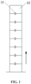
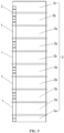
- FIG. 1 in the conventional household energy storage system, eight modules 02 are stacked in sequence in a vertical direction, where the vertical direction is shown by the arrow in FIG. 1 .
- Two adjacent modules 02 are fixedly connected through a fixing member 01. Specifically, one of the two adjacent modules 02 is fixedly connected to one end of the fixing member 01 and the other of the two adjacent modules 02 is fixedly connected to the other end of the fixing member 01.
- the household energy storage system is usually installed by a third party or by the customer, and the above fixing structure increases the complexity of on-site installation and on-site maintenance.
- a module fixing structure of a household energy storage system is provided according to embodiments of the present application.
- the module fixing structure includes multiple modules 3 and at least one first fixing member 1.
- the modules 3 are stacked in at least one stacking direction; the first fixing member 1 stretches across M modules 3 of the modules 3 in a stacking direction in which N modules 3 are stacked, and only two ends of the first fixing member 1 are fixed to two of the multiple modules 3, respectively.
- N is a positive integer greater than or equal to 3
- M is a positive integer less than or equal to N-2.
- the first fixing member 1 includes two fixing portions 111 and a stretching-across portion 112 located between the two fixing portions 111.
- One fixing portion 111 is fixedly connected to one end of the stretching-across portion 112, and the other fixing portion 111 is fixedly connected to the other end of the stretching-across portion 112, and the fixing portion 111 is fixedly connected to the corresponding module 3.
- the first fixing member 1 may be a one-piece structure or a split structure, depending on the actual needs.
- the first fixing member 1 stretches across the M modules 3 in the stacking direction in which N modules 3 are stacked, which effectively reduces the number of the first fixing member 1 and the number of fixed connections. Therefore, with the above module fixing structure, the convenience of installation and maintenance is improved.
- the number of the first fixing member 1 may be one, or two or more. In a case that the number of the first fixing member 1 is at least two, the at least two first fixing members 1 may stretch across the same number of modules 3, and/or, the at least two first fixing members 1 may stretch across different numbers of modules 3.
- the number of modules 3 across which each of first fixing members 1 stretches is selected according to actual needs, so that the form of fixing can be varied according to the actual situation without changing the number of fixing connections, which improves flexibility and further improves the convenience of installation and maintenance, thereby improving adaptability to complex installation environments.
- the above stacking direction may be one, or two or more, depending on the actual needs.
- the specific direction of the above stacking direction is also selected according to actual needs.
- the stacking direction is a vertical direction and/or a horizontal direction. It is understood that the horizontal direction is perpendicular to the vertical direction.
- the stacking direction in which N modules 3 are stacked is a vertical direction and/or a horizontal direction.
- the above modules 3 are usually of a rectangular cuboid shape, the above vertical direction is a height direction of the modules 3, and the above horizontal direction is a length direction and/or a width direction of the modules 3.
- the stacking direction in which N modules 3 are stacked is the height direction of the modules 3, and/or the length direction of the modules 3, and/or the width direction of the modules 3.
- the arrow lines shown in FIGS. 2 , 3 , 10 and 11 indicate the vertical direction
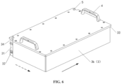
- the solid arrow line in FIG. 6 indicates the length direction of the modules 3
- the dashed arrow line in FIG. 6 indicates the width direction of the modules 3
- the horizontal arrow line in FIG. 12 indicates the horizontal direction
- the vertical arrow line in FIG. 12 indicates the vertical direction.
- two adjacent modules 3 fit with each other by positioning in the stacking direction.
- the specific structure of the fitting and positioning of the two modules 3 is selected according to actual needs.
- one of the two adjacent modules 3 is provided with at least one positioning groove
- the other of the two adjacent modules 3 is provided with at least one positioning member
- the positioning member and the positioning groove fit with each other by positioning.
- the specific structure and the specific number of the above positioning member and the positioning groove may be selected according to actual needs, which are not limited in the embodiment.
- two or more positioning members and two or more positioning grooves are provided; where at least one of the positioning members is a first positioning member 4, at least one of the positioning grooves is a first positioning groove 6, and the first positioning member 4 and the first positioning groove 6 fit with each other by positioning; at least another one of the positioning members is a second positioning member 5, at least another one of the positioning grooves is a second positioning groove 7, and the second positioning member 5 and the second positioning groove 7 fit with each other by positioning.
- a fit accuracy between the first positioning member 4 and the first positioning groove 6 is less than that between the second positioning member 5 and the second positioning groove 7.
- coarse positioning i.e., primary positioning
- fine positioning i.e., secondary positioning
- the modules 3 each is provided with a handle.
- the first positioning member 4 is embodied as the handle and the first positioning groove 6 may be a handle groove, where the handle is located at a top of the module 3 having the handle and the handle groove is located at a bottom of the module 3 having the handle groove. In this way, coarse positioning can be realized by the handle and the handle groove, which makes full use of the handle structure of the module 3 itself, and thereby the structure is simplified.
- coarse positioning can be realized by means of other positioning structures, which are not limited to the above embodiments.
- the second positioning member 5 may be a positioning rod and the second positioning groove 7 may be a positioning rod groove.
- the first positioning member 4 is a handle
- the module 3 is of a rectangular cuboid shape
- the number of the handle on the module 3 is two and the two handles are distributed in sequence in the length direction of the module 3, and the length direction of the handles parallel to the width direction of the module 3.
- the second positioning member 5 is a positioning rod
- the module 3 is of a rectangular cuboid shape
- the number of the positioning rod is at least two and the at least two positioning rods are distributed in sequence in the length direction, width direction or diagonal direction of the module 3.
- the first fixing member 1 may be fixedly connected to the module 3 in a detachable manner.
- the first fixing member 1 and the module 3 are fixedly connected through a threaded connecting member, so that the structure is simple and the fixing is reliable.
- the first fixing member 1 and module 3 are fixedly connected through screws.
- the first fixing member 1 is provided with first fixing holes 13 for the screws to pass through, and each of the first fixing holes 13 is a countersunk hole. In this way, the screws can be hidden and the appearance is improved.
- the structure for fixing the first fixing member 1 and the module 3 is not limited to the above way, and the first fixing member 1 may be fixed to the modules 3 by using one of manners or a combination of at least two of the manners of a binding member, a snap-on structure and a clamping member.
- the specific structures of the first fixing member 1 and the modules 3 may be selected according to actual needs. As shown in FIGS. 6 and 7 , the above module 3 is provided with a first mounting notch 31, and the first fixing member 1 is fixed at the first mounting notch 31.
- the first mounting notch 31 and the first fixing member 1 may fit with each other by positioning. In this way, the positioning effect of the first mounting notch 31 on the first fixing member 1 during installation prevents the first fixing member from being deflected during the fixation, thus facilitating fixing the first fixing member and also improving the fixing efficiency.
- the first fixing member 1 may be flush with the modules 3 at which the first fixing member 1 is located, so that the first fixing member 1 does not protrude from the modules 3 after the entire first fixing member 1 is mounted at the modules 3, which effectively improves the appearance and reduces the size of the entire structure.
- the first fixing member 1 if the first fixing member 1 is flush with the modules 3 on which the first fixing member 1 is located and at least one module 3 is provided with a first flange 33 in a circumferential direction, the first flange 33 may have a first flange notch 34.
- the first fixing member 1 includes a first fixing plate 11 and a first protruding portion 12 provided on the first fixing plate 11. The first fixing plate 11 is fixed at the first mounting notch 31 and the first fixing plate 11 is flush with the modules 3 at which the first fixing plate 11 is located.
- the first protruding portion 12 is located at the first flange notch 34, and the first protruding portion 12 and the first flange 33 at which the first protruding portion 12 is located are flush with each other and abutted to each other to form a closed loop structure.
- first mounting notch 31 and the first fixing member 1 fit with each other by positioning
- first mounting notch 31 and the first fixing plate 11 fit with each other by positioning.
- the number of the first protruding portion 12 in the first fixing member 1 is related to the number of modules 3 across which the first fixing member 1 stretches, which is not limited in this embodiment.
- the module 3 may be provided with a first mounting boss 32 at the first mounting notch 31.
- the first mounting boss 32 is provided with a mounting hole for fixing the first fixing member 1.
- the module 3 is of a rectangular cuboid shape
- the first fixing member 1 may be arranged on an edge of the module 3, as shown in FIGS. 3 to 5 .
- the first fixing member 1 may be arranged between two edges of the module 3.
- the module fixing structure of a household energy storage system, if after the modules 3 is fixed by using the first fixing member 1, only one module 3 remains unfixed in the stacking direction, and the only one module 3 remained in the stacking direction may be fixed by using a second fixing member 2.
- the second fixing member 2 is fixedly connected to two adjacent modules 3 in the stacking direction. Therefore, based on the above situations, the module fixing structure further includes a second fixing member 2 which is fixedly connected to two adjacent modules 3 in the stacking direction.
- the second fixing member 2 may be fixedly connected to the modules 3 in a detachable manner.
- the second fixing member 2 and the modules 3 are fixedly connected through a threaded connecting member, so that the structure is simple and the fixing is reliable.
- the second fixing member 2 and the module 3 are fixedly connected through screws.
- the second fixing member 2 is provided with second fixing holes 23 for the screws to pass through, and each of the second fixing holes 23 is a countersunk hole. In this way, the screws can be hidden and the appearance is improved.
- the structure for fixing the second fixing member 2 to the modules 3 is not limited to the above manners, and the second fixing member 2 may be fixed to the modules 3 by using one of manners or a combination of at least two of the manners of a binding member, a snap-on structure and a clamping member.
- the module 3 is provided with a second mounting notch, and the second fixing member 2 is fixed at the second mounting notch.
- the second mounting notch and the second fixing member 2 may fit with each other by positioning. In this way, the positioning effect of the second mounting notch on the second fixing member 2 during installation prevents the second fixing member 2 from being deflected during the fixation, thus facilitating fixing the second fixing member 2 and also improving the fixing efficiency.
- the second fixing member 2 may be flush with the modules 3 at which the second fixing member 2 is located, so that the second fixing member 2 does not protrude from the modules 3 after the entire second fixing member 2 is mounted at the modules 3, which effectively improves the appearance and reduces the size of the entire structure.
- the second fixing member 1 if the second fixing member 1 is flush with the modules 3at which the second fixing member 1 is located and at least one module 3 is provided with a second flange in a circumferential direction, the second flange may have a second flange notch.
- the second fixing member 2 includes a second fixing plate 21 and a second protruding portion 22 provided on the second fixing plate 21. The second fixing plate 21 is fixed at the second mounting notch, and the second fixing plate 21 is flush with the modules 3 at which the second fixing plate 21 is located.
- the second protruding portion 22 is located at the second flange notch, and the second protruding portion 22 and the second flange at which the second protruding portion 22 is located are flush with each other and abutted to each other to form a closed loop structure.
- the second mounting notch may be referred to the first mounting notch 31, the second flange may be referred to the first flange 33, and the second flange notch may be referred to the first flange notch 34. If the second mounting notch and the second fixing member 2 fit with each other by positioning, the second mounting notch and the second fixing member 21 fit with each other by positioning.
- the second protruding portion 22 is located in a middle of the second fixing member 2, and the second fixing holes 23 are located at two ends of the second fixing member 2.
- the module 3 is of a rectangular cuboid shape
- the second fixing member 2 may be arranged on an edge of the module 3 or between two edges of the module 3.
- the module 3 refers to a functional module that can be included in the household energy storage system or a structural module that can be stacked in the household energy storage system.
- the functional module may be an energy storage module, a power control module, an inverter module, or a heat dissipation module, and the above structural module may be a base or a top cover, or the like. If the household energy storage system is a light storage and charging system, alternatively, the functional module may be a photovoltaic power generation module.
- At least one module 3 may be a functional module and at least two modules 3 may be structural modules, or at least two modules 3 may be functional modules and at least one module 3 may be a structural module.
- each of the modules 3 may be a functional module.
- each of the modules 3 may be a structural module.
- the at least two functional modules may be the same or different; and in a case that at least two modules 3 are structural modules, the at least two structural modules may be the same or different.
- a module fixing structure of a household energy storage system includes multiple modules 3, at least one first fixing member 1, and at least one second fixing member 2.
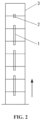
- the multiple modules 3 are stacked in a vertical direction.
- the second fixing member 2 is fixedly connected to two topmost modules 3, and the remaining modules 3 are fixedly connected by the first fixing member 1.
- the first fixing member 1 extends along a vertical direction, the first fixing member 1 stretches across at least one module 3, and only two ends of the first fixing member 1 are fixed to the other two modules 3, respectively.
- the number of the modules 3 is eight, the number of the first fixing member 1 is three, each of the first fixing member 1 stretches across one module 3, and the number of the second fixing member 2 is one.
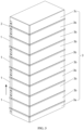
- the number of the modules 3 is ten, the number of the first fixing member 1 is four, each of the first fixing member 1 stretches across one module 3, and the number of the second fixing member 2 is one.
- the position of the second fixing member 2 may be adjusted, for example the second fixing member 2 is fixedly connected to two bottommost modules 3, which is not limited to the positions shown in FIGS. 2 and 3 .
- modules 3 may be selected according to actual needs. As shown in FIG. 3 , in the vertical direction, a module 3 at the bottommost end is a base 3a, a module 3 at the topmost end is a top cover 3c, and modules 3 between the base 3a and the top cover 3c are functional modules 3b.
- the modules 3 may have other types and are not limited to the above embodiment.
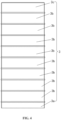
- the second embodiment differs from the first embodiment mainly in the number of modules 3 across which the first fixing member 1 stretches.
- the number of the modules 3 is eight
- the first fixing member 1 is two
- the number of the second fixing member 2 is one
- each of the first fixing member 1 stretches across two modules 3.
- the number of the modules 3 across which the first fixing member 1 stretches may be three, or four or more, and is not limited to two.
- the third embodiment differs from the first embodiment mainly in that no second fixing member is provided.
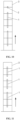
- a module fixing structure of a household energy storage system includes multiple modules 3 and at least two first fixing members 1.
- the multiple modules 3 are stacked in a vertical direction, the first fixing member 1 extends along the vertical direction, and the at least two first fixing members 1 are distributed in sequence in the vertical direction.
- the first fixing member 1 stretches across at least one of the modules 3, and only two ends of the first fixing member 1 are fixed to two modules 3, respectively.
- the number of the modules 3 across which each of the at least two first fixing members 1 stretches is different. Specifically, as shown in FIG. 11 , the number of the modules 3 is eight, the number of the first fixing member 1 is three, two of the three first fixing members 1 each stretches across one module 3, and the other one of the three first fixing members 1stretches across two modules 3.
- the number of the modules 3 across which the first fixing member 1 stretches maybe other values, which is not limited to one or two.
- the fourth embodiment differs from the first embodiment mainly in the stacking direction of the modules 3.
- a module fixing structure of a household energy storage system includes multiple modules 3, at least two first fixing members 1, and at least one second fixing member 2.
- the modules 3 are stacked both in a vertical direction and in a horizontal direction.
- the second fixing member 2 is fixedly connected to two adjacent modules 3
- at least one first fixing member 1 stretches across at least one module 3, and only two ends of the first fixing member 1 are fixedly connected to two modules 3, respectively.
- In the horizontal direction at least one first fixing member 1 stretches across at least one module 3, and only two ends of the first fixing member 1 are fixedly connected to two modules 3, respectively.
- the modules 3 stacked in the vertical direction are referred to as module columns, and the modules 3 stacked in the horizontal direction are referred to as module rows.
- the modules 3 are fixed by the first fixing member 1 in a stretching-across manner.
- the topmost two modules 3 are fixedly connected by the second fixing member 2, and the other modules 3 are fixed by the first fixing member 1 in a stretching-across manner.
- modules in other module rows 3 may be fixed by the first fixing member 1 in a stretching-across manner according to actual needs, which is not limited to the above embodiments.
- the horizontal direction may be a width direction of the modules 3, which is not limited to the direction shown in FIG. 12 ; the modules 3 may be stacked in the vertical direction and in the length direction of the modules 3, and also in the width direction of the modules 3, which is not limited to the two stacking directions shown in FIG. 12 .
- a household energy storage system is further provided.
- the household energy storage system includes the module fixing structure according to the above embodiments.
- the module fixing structure according to the above embodiments has the technical effects described above, and the household energy storage system includes the module fixing structure of a household energy storage system, the above household energy storage system also has the corresponding technical effects, which will not be repeated herein.
Landscapes
- Chemical & Material Sciences (AREA)
- Chemical Kinetics & Catalysis (AREA)
- Electrochemistry (AREA)
- General Chemical & Material Sciences (AREA)
- Engineering & Computer Science (AREA)
- Power Engineering (AREA)
- Microelectronics & Electronic Packaging (AREA)
- Battery Mounting, Suspending (AREA)
- Supply And Distribution Of Alternating Current (AREA)
- Connector Housings Or Holding Contact Members (AREA)
Claims (16)
- Modulbefestigungsstruktur, die auf ein Haushaltsenergiespeichersystem anwendbar ist, umfassend:eine Vielzahl von Modulen (3) und mindestens ein erstes Befestigungselement (1); wobeidie Vielzahl von Modulen (3) in mindestens einer Stapelrichtung gestapelt ist;in einer Stapelrichtung der mindestens einen Stapelrichtung, in der N Module (3) der Vielzahl von Modulen (3) gestapelt sind, sich das erste Befestigungselement (1) über M Module (3) der Vielzahl von Modulen (3) erstreckt, lediglich zwei Enden des ersten Befestigungselements (1) jeweils an zwei der Vielzahl von Modulen (3) befestigt sind und sich die M Module (3) zwischen den zwei Enden des ersten Befestigungselements (1) befinden und nicht fest mit dem ersten Befestigungselement (1) verbunden sind; wobeiN eine positive ganze Zahl größer oder gleich 3 ist und M eine positive ganze Zahl kleiner oder gleich N-2 ist.
- Modulbefestigungsstruktur nach Anspruch 1, wobeidie Anzahl des ersten Befestigungselements (1) mindestens zwei beträgt; undsich die mindestens zwei ersten Befestigungselemente (1) über eine gleiche Anzahl von Modulen (3) erstrecken; und/oder sich die mindestens zwei ersten Befestigungselemente (1) über unterschiedliche Anzahlen von Modulen (3) erstrecken.
- Modulbefestigungsstruktur nach Anspruch 1, wobei die Stapelrichtung, in der die N Module (3) gestapelt sind, eine vertikale Richtung und/oder eine horizontale Richtung ist.
- Modulbefestigungsstruktur nach Anspruch 3, wobei jedes der Vielzahl von Modulen (3) eine rechteckige Quaderform aufweist, die vertikale Richtung eine Höhenrichtung der Module (3) ist und die horizontale Richtung eine Längenrichtung und/oder eine Breitenrichtung der Module (3) ist.
- Modulbefestigungsstruktur nach Anspruch 1, wobei zwei benachbarte Module (3) der Vielzahl von Modulen (3) durch Positionieren in der Stapelrichtung ineinander passen.
- Modulbefestigungsstruktur nach Anspruch 5, wobei in der Stapelrichtung eines der zwei benachbarten Module (3) mit mindestens einer Positionierungsnut bereitgestellt ist, das andere der zwei benachbarten Module (3) mit mindestens einem Positionierungselement bereitgestellt ist und das Positionierungselement und die Positionierungsnut durch Positionieren ineinander passen.
- Modulbefestigungsstruktur nach Anspruch 6, wobeidie Anzahl des mindestens einen Positionierungselements zwei oder mehr beträgt und die Anzahl der mindestens einen Positionierungsnut zwei oder mehr beträgt; wobeimindestens eines der zwei oder mehr Positionierungselemente ein erstes Positionierungselement (4) ist, mindestens eine der zwei oder mehr Positionierungsnuten eine erste Positionierungsnut (6) ist und das erste Positionierungselement (4) und die erste Positionierungsnut (6) durch Positionieren ineinander passen; undmindestens ein anderes der zwei oder mehr Positionierungselemente ein zweites Positionierungselement (5) ist, mindestens eine andere der zwei oder mehr Positionierungsnuten eine zweite Positionierungsnut (7) ist und das zweite Positionierungselement (5) und die zweite Positionierungsnut (7) durch Positionieren ineinander passen; und wobeieine Passgenauigkeit zwischen dem ersten Positionierungselement (4) und der ersten Positionierungsnut (6) kleiner als diejenige zwischen dem zweiten Positionierungselement (5) und der zweiten Positionierungsnut (7) ist.
- Modulbefestigungsstruktur nach Anspruch 7, wobeidie Stapelrichtung eine vertikale Richtung ist, das erste Positionierungselement (4) ein Griff ist, die erste Positionierungsnut (6) eine Griffnut ist, der Griff oben an dem anderen der zwei benachbarten Module (3) angeordnet ist und die Griffnut unten an dem einen der zwei benachbarten Module (3) angeordnet ist; unddas zweite Positionierungselement (5) eine Positionierungsstange ist und die zweite Positionierungsnut (7) eine Positionierungsstangennut ist.
- Modulbefestigungsstruktur nach Anspruch 1, wobei das erste Befestigungselement (1) auf eine abnehmbare Weise fest mit den Modulen (3) verbunden ist.
- Modulbefestigungsstruktur nach Anspruch 1, wobei das Modul (3) mit einer ersten Montagekerbe (31) bereitgestellt ist, wobei die erste Montagekerbe (31) und das erste Befestigungselement (1) durch Positionieren ineinander passen und/oder das erste Befestigungselement (1) und die Module (3), an denen sich das erste Befestigungselement (1) befindet, miteinander bündig sind; und das erste Befestigungselement (1) an der ersten Montagekerbe (31) befestigt ist.
- Modulbefestigungsstruktur nach Anspruch 10, wobeiin einem Fall, in dem das erste Befestigungselement (1) und die Module (3), an denen sich das erste Befestigungselement (1) befindet, bündig miteinander sind, mindestens eines der Module (3) mit einem ersten Flansch (33) in einer Umfangsrichtung bereitgestellt ist, der erste Flansch (33) eine erste Flanschkerbe (34) aufweist; und das erste Befestigungselement (1) eine erste Befestigungsplatte (11) und einen ersten vorstehenden Abschnitt (12) umfasst, der an der ersten Befestigungsplatte (11) bereitgestellt ist; wobeidie erste Befestigungsplatte (11) an der ersten Montagekerbe (31) befestigt ist und die erste Befestigungsplatte (11) und die Module (3), an denen sich das erste Befestigungselement (1) befindet, bündig miteinander sind; der erste vorstehende Abschnitt (12) an der ersten Flanschkerbe (34) angeordnet ist und der erste vorstehende Abschnitt (12) und der erste Flansch (33) bündig miteinander sind und aneinander anliegen, um eine geschlossene Schleifenstruktur zu bilden.
- Modulbefestigungsstruktur nach Anspruch 1, ferner umfassend ein zweites Befestigungselement (2), wobei das zweite Befestigungselement (2) dazu konfiguriert ist, zwei benachbarte Module (3) der Vielzahl von Modulen (3) in der Stapelrichtung fest zu verbinden.
- Modulbefestigungsstruktur nach Anspruch 12, wobei jedes der zwei benachbarten Module (3) der Vielzahl der Module (3) mit einer zweiten Montagekerbe bereitgestellt ist, die zweite Montagekerbe und das zweite Befestigungselement (2) durch Positionieren ineinander passen und/oder das zweite Befestigungselement (2) und die zwei benachbarten Module (3), mit denen das zweite Befestigungselement (2) verbunden ist, miteinander bündig sind; und das zweite Befestigungselement (2) an der zweiten Montagekerbe befestigt ist.
- Modulbefestigungsstruktur nach Anspruch 13, wobeiin einem Fall, in dem das zweite Befestigungselement (2) und die zwei benachbarten Module (3), mit denen das zweite Befestigungselement (2) verbunden ist, miteinander bündig sind, mindestens eines der zwei benachbarten Module (3) mit einem zweiten Flansch in einer Umfangsrichtung bereitgestellt ist, der zweite Flansch eine zweite Flanschkerbe aufweist; und das zweite Befestigungselement (2) eine zweite Befestigungsplatte und einen zweiten vorstehenden Abschnitt umfasst, der an der zweiten Befestigungsplatte bereitgestellt ist;wobei die zweite Befestigungsplatte an der zweiten Montagekerbe befestigt ist und die zweite Befestigungsplatte und die zwei benachbarten Module (3), mit denen die zweite Befestigungsplatte verbunden ist, miteinander bündig sind; der zweite vorstehende Abschnitt an der zweiten Flanschkerbe angeordnet ist und der zweite vorstehende Abschnitt und der zweite Flansch, an dem der zweite vorstehende Abschnitt angeordnet ist, bündig miteinander sind und aneinander anliegen, um eine geschlossene Schleifenstruktur zu bilden.
- Modulbefestigungsstruktur nach einem der Ansprüche 1 bis 14, wobeimindestens zwei der Module (3) Funktionsmodule sind und mindestens eines der Module (3) ein Strukturmodul ist; oder mindestens eines der Module (3) ein Funktionsmodul ist und mindestens zwei der Module (3) Strukturmodule sind; oder jedes der Module (3) ein Funktionsmodul ist; und wobeidas Funktionsmodul ein Energiespeichermodul, ein Leistungssteuermodul, ein Wechselrichtermodul, ein Fotovoltaik-Leistungserzeugungsmodul oder ein Wärmeableitungsmodul ist und das Strukturmodul eine Basis oder eine obere Abdeckung ist.
- Haushaltsenergiespeichersystem, umfassend die Modulbefestigungsstruktur nach einem der Ansprüche 1 bis 15.
Applications Claiming Priority (1)
| Application Number | Priority Date | Filing Date | Title |
|---|---|---|---|
| CN202222241717.8U CN218783743U (zh) | 2022-08-24 | 2022-08-24 | 户用储能系统及其模块固定结构 |
Publications (3)
| Publication Number | Publication Date |
|---|---|
| EP4333176A1 EP4333176A1 (de) | 2024-03-06 |
| EP4333176C0 EP4333176C0 (de) | 2025-02-12 |
| EP4333176B1 true EP4333176B1 (de) | 2025-02-12 |
Family
ID=85707030
Family Applications (1)
| Application Number | Title | Priority Date | Filing Date |
|---|---|---|---|
| EP23185109.8A Active EP4333176B1 (de) | 2022-08-24 | 2023-07-12 | Haushaltsenergiespeichersystem und modulbefestigungsstruktur dafür |
Country Status (5)
| Country | Link |
|---|---|
| US (1) | US20240072361A1 (de) |
| EP (1) | EP4333176B1 (de) |
| CN (1) | CN218783743U (de) |
| AU (1) | AU2023204407B2 (de) |
| ZA (1) | ZA202307286B (de) |
Families Citing this family (2)
| Publication number | Priority date | Publication date | Assignee | Title |
|---|---|---|---|---|
| CN118448798A (zh) * | 2024-05-27 | 2024-08-06 | 厦门新能达科技有限公司 | 电池模组、储能设备及其安装方法 |
| CN223436605U (zh) * | 2024-09-29 | 2025-10-14 | 惠州亿纬锂能股份有限公司 | 电池箱及电池包 |
Family Cites Families (2)
| Publication number | Priority date | Publication date | Assignee | Title |
|---|---|---|---|---|
| CN111900502A (zh) * | 2020-08-21 | 2020-11-06 | 阳光电源股份有限公司 | 储能柜 |
| CN215644823U (zh) * | 2021-07-28 | 2022-01-25 | 天合光能股份有限公司 | 储能单元及使用该储能单元的储能电池 |
-
2022
- 2022-08-24 CN CN202222241717.8U patent/CN218783743U/zh active Active
-
2023
- 2023-07-07 AU AU2023204407A patent/AU2023204407B2/en active Active
- 2023-07-10 US US18/349,810 patent/US20240072361A1/en active Pending
- 2023-07-12 EP EP23185109.8A patent/EP4333176B1/de active Active
- 2023-07-21 ZA ZA2023/07286A patent/ZA202307286B/en unknown
Also Published As
| Publication number | Publication date |
|---|---|
| EP4333176C0 (de) | 2025-02-12 |
| AU2023204407A1 (en) | 2024-03-14 |
| CN218783743U (zh) | 2023-03-31 |
| EP4333176A1 (de) | 2024-03-06 |
| US20240072361A1 (en) | 2024-02-29 |
| AU2023204407B2 (en) | 2025-01-23 |
| ZA202307286B (en) | 2024-03-27 |
Similar Documents
| Publication | Publication Date | Title |
|---|---|---|
| EP4333176B1 (de) | Haushaltsenergiespeichersystem und modulbefestigungsstruktur dafür | |
| US9154074B2 (en) | Apparatus for forming and mounting a photovoltaic array | |
| US9243817B2 (en) | Apparatus for forming and mounting a photovoltaic array | |
| KR101953446B1 (ko) | 태양 전지판 기계적 커넥터 및 프레임 | |
| US20100043862A1 (en) | Solar Panel Interconnection System | |
| CN109769410B (zh) | 具有朝向角部电连接器端口的光伏组件 | |
| EP3621420B1 (de) | Fotovoltaischer wechselrichter | |
| US20240332711A1 (en) | Stacked power supply modules | |
| US20250286508A1 (en) | Solar panel assembly method | |
| CN218448314U (zh) | 一种户用储能系统 | |
| WO2024198317A1 (zh) | 可调节浮体、漂浮系统和水面光伏电站 | |
| KR20220018683A (ko) | 양면 수광형 태양광 모듈 프레임 및 양면 수광형 태양광 시스템 | |
| JP7791333B2 (ja) | 電気機器、電気機器掛装システム及び太陽光発電所 | |
| CN210123948U (zh) | 一种连接器 | |
| EP4597712A1 (de) | Batteriemodul, energiespeichervorrichtung und energiespeichersystem | |
| CN209545286U (zh) | 磁极模块、转子和电机 | |
| CN219180679U (zh) | 一种储能系统 | |
| CN220106744U (zh) | 电池模组 | |
| CN206921873U (zh) | 一种电池模组 | |
| CN216948725U (zh) | 一种新型抗震铰链底座 | |
| CN216056929U (zh) | 一体式接线装置 | |
| CN217469866U (zh) | 一种便于固定的光伏组件边框 | |
| CN217427930U (zh) | 一种拼块式直线电机铁芯的安装结构 | |
| CN219164059U (zh) | 一种大跨距高承重绝缘隔离的安装机构及安装组件 | |
| CN219937210U (zh) | 一种模组框架及模组 |
Legal Events
| Date | Code | Title | Description |
|---|---|---|---|
| PUAI | Public reference made under article 153(3) epc to a published international application that has entered the european phase |
Free format text: ORIGINAL CODE: 0009012 |
|
| STAA | Information on the status of an ep patent application or granted ep patent |
Free format text: STATUS: REQUEST FOR EXAMINATION WAS MADE |
|
| 17P | Request for examination filed |
Effective date: 20230712 |
|
| AK | Designated contracting states |
Kind code of ref document: A1 Designated state(s): AL AT BE BG CH CY CZ DE DK EE ES FI FR GB GR HR HU IE IS IT LI LT LU LV MC ME MK MT NL NO PL PT RO RS SE SI SK SM TR |
|
| GRAP | Despatch of communication of intention to grant a patent |
Free format text: ORIGINAL CODE: EPIDOSNIGR1 |
|
| STAA | Information on the status of an ep patent application or granted ep patent |
Free format text: STATUS: GRANT OF PATENT IS INTENDED |
|
| INTG | Intention to grant announced |
Effective date: 20240919 |
|
| GRAS | Grant fee paid |
Free format text: ORIGINAL CODE: EPIDOSNIGR3 |
|
| GRAA | (expected) grant |
Free format text: ORIGINAL CODE: 0009210 |
|
| STAA | Information on the status of an ep patent application or granted ep patent |
Free format text: STATUS: THE PATENT HAS BEEN GRANTED |
|
| AK | Designated contracting states |
Kind code of ref document: B1 Designated state(s): AL AT BE BG CH CY CZ DE DK EE ES FI FR GB GR HR HU IE IS IT LI LT LU LV MC ME MK MT NL NO PL PT RO RS SE SI SK SM TR |
|
| REG | Reference to a national code |
Ref country code: GB Ref legal event code: FG4D |
|
| REG | Reference to a national code |
Ref country code: CH Ref legal event code: EP |
|
| REG | Reference to a national code |
Ref country code: DE Ref legal event code: R096 Ref document number: 602023001991 Country of ref document: DE |
|
| REG | Reference to a national code |
Ref country code: IE Ref legal event code: FG4D |
|
| U01 | Request for unitary effect filed |
Effective date: 20250303 |
|
| U07 | Unitary effect registered |
Designated state(s): AT BE BG DE DK EE FI FR IT LT LU LV MT NL PT RO SE SI Effective date: 20250310 |
|
| PG25 | Lapsed in a contracting state [announced via postgrant information from national office to epo] |
Ref country code: RS Free format text: LAPSE BECAUSE OF FAILURE TO SUBMIT A TRANSLATION OF THE DESCRIPTION OR TO PAY THE FEE WITHIN THE PRESCRIBED TIME-LIMIT Effective date: 20250512 |
|
| PG25 | Lapsed in a contracting state [announced via postgrant information from national office to epo] |
Ref country code: PL Free format text: LAPSE BECAUSE OF FAILURE TO SUBMIT A TRANSLATION OF THE DESCRIPTION OR TO PAY THE FEE WITHIN THE PRESCRIBED TIME-LIMIT Effective date: 20250212 |
|
| PG25 | Lapsed in a contracting state [announced via postgrant information from national office to epo] |
Ref country code: ES Free format text: LAPSE BECAUSE OF FAILURE TO SUBMIT A TRANSLATION OF THE DESCRIPTION OR TO PAY THE FEE WITHIN THE PRESCRIBED TIME-LIMIT Effective date: 20250212 |
|
| PG25 | Lapsed in a contracting state [announced via postgrant information from national office to epo] |
Ref country code: IS Free format text: LAPSE BECAUSE OF FAILURE TO SUBMIT A TRANSLATION OF THE DESCRIPTION OR TO PAY THE FEE WITHIN THE PRESCRIBED TIME-LIMIT Effective date: 20250612 Ref country code: NO Free format text: LAPSE BECAUSE OF FAILURE TO SUBMIT A TRANSLATION OF THE DESCRIPTION OR TO PAY THE FEE WITHIN THE PRESCRIBED TIME-LIMIT Effective date: 20250512 |
|
| PG25 | Lapsed in a contracting state [announced via postgrant information from national office to epo] |
Ref country code: HR Free format text: LAPSE BECAUSE OF FAILURE TO SUBMIT A TRANSLATION OF THE DESCRIPTION OR TO PAY THE FEE WITHIN THE PRESCRIBED TIME-LIMIT Effective date: 20250212 |
|
| PG25 | Lapsed in a contracting state [announced via postgrant information from national office to epo] |
Ref country code: GR Free format text: LAPSE BECAUSE OF FAILURE TO SUBMIT A TRANSLATION OF THE DESCRIPTION OR TO PAY THE FEE WITHIN THE PRESCRIBED TIME-LIMIT Effective date: 20250513 |
|
| U20 | Renewal fee for the european patent with unitary effect paid |
Year of fee payment: 3 Effective date: 20250725 |
|
| PG25 | Lapsed in a contracting state [announced via postgrant information from national office to epo] |
Ref country code: SM Free format text: LAPSE BECAUSE OF FAILURE TO SUBMIT A TRANSLATION OF THE DESCRIPTION OR TO PAY THE FEE WITHIN THE PRESCRIBED TIME-LIMIT Effective date: 20250212 |
|
| PG25 | Lapsed in a contracting state [announced via postgrant information from national office to epo] |
Ref country code: CZ Free format text: LAPSE BECAUSE OF FAILURE TO SUBMIT A TRANSLATION OF THE DESCRIPTION OR TO PAY THE FEE WITHIN THE PRESCRIBED TIME-LIMIT Effective date: 20250212 |
|
| PG25 | Lapsed in a contracting state [announced via postgrant information from national office to epo] |
Ref country code: SK Free format text: LAPSE BECAUSE OF FAILURE TO SUBMIT A TRANSLATION OF THE DESCRIPTION OR TO PAY THE FEE WITHIN THE PRESCRIBED TIME-LIMIT Effective date: 20250212 |
|
| PLBE | No opposition filed within time limit |
Free format text: ORIGINAL CODE: 0009261 |
|
| STAA | Information on the status of an ep patent application or granted ep patent |
Free format text: STATUS: NO OPPOSITION FILED WITHIN TIME LIMIT |
|
| 26N | No opposition filed |
Effective date: 20251113 |