EP4332322A2 - Floor panel and floor panel assembly process - Google Patents
Floor panel and floor panel assembly process Download PDFInfo
- Publication number
- EP4332322A2 EP4332322A2 EP23193654.3A EP23193654A EP4332322A2 EP 4332322 A2 EP4332322 A2 EP 4332322A2 EP 23193654 A EP23193654 A EP 23193654A EP 4332322 A2 EP4332322 A2 EP 4332322A2
- Authority
- EP
- European Patent Office
- Prior art keywords
- floor
- floor panel
- grooves
- receiving element
- vertical
- Prior art date
- Legal status (The legal status is an assumption and is not a legal conclusion. Google has not performed a legal analysis and makes no representation as to the accuracy of the status listed.)
- Pending
Links
- 238000000034 method Methods 0.000 title claims description 10
- 238000009434 installation Methods 0.000 claims abstract description 25
- 238000009408 flooring Methods 0.000 claims abstract description 24
- 230000007704 transition Effects 0.000 claims description 3
- 239000000463 material Substances 0.000 claims description 2
- 238000005520 cutting process Methods 0.000 description 10
- 238000009413 insulation Methods 0.000 description 3
- 238000007373 indentation Methods 0.000 description 2
- 239000000853 adhesive Substances 0.000 description 1
- 230000001070 adhesive effect Effects 0.000 description 1
- 238000010276 construction Methods 0.000 description 1
- 239000012535 impurity Substances 0.000 description 1
- 239000002245 particle Substances 0.000 description 1
- 238000010094 polymer processing Methods 0.000 description 1
- 238000009417 prefabrication Methods 0.000 description 1
- 239000000758 substrate Substances 0.000 description 1
Images


Classifications
-
- E—FIXED CONSTRUCTIONS
- E04—BUILDING
- E04F—FINISHING WORK ON BUILDINGS, e.g. STAIRS, FLOORS
- E04F15/00—Flooring
- E04F15/02—Flooring or floor layers composed of a number of similar elements
- E04F15/02038—Flooring or floor layers composed of a number of similar elements characterised by tongue and groove connections between neighbouring flooring elements
-
- E—FIXED CONSTRUCTIONS
- E04—BUILDING
- E04F—FINISHING WORK ON BUILDINGS, e.g. STAIRS, FLOORS
- E04F15/00—Flooring
- E04F15/02—Flooring or floor layers composed of a number of similar elements
- E04F15/02005—Construction of joints, e.g. dividing strips
-
- E—FIXED CONSTRUCTIONS
- E04—BUILDING
- E04F—FINISHING WORK ON BUILDINGS, e.g. STAIRS, FLOORS
- E04F2201/00—Joining sheets or plates or panels
- E04F2201/01—Joining sheets, plates or panels with edges in abutting relationship
- E04F2201/0153—Joining sheets, plates or panels with edges in abutting relationship by rotating the sheets, plates or panels around an axis which is parallel to the abutting edges, possibly combined with a sliding movement
-
- E—FIXED CONSTRUCTIONS
- E04—BUILDING
- E04F—FINISHING WORK ON BUILDINGS, e.g. STAIRS, FLOORS
- E04F2203/00—Specially structured or shaped covering, lining or flooring elements not otherwise provided for
- E04F2203/08—Specially structured or shaped covering, lining or flooring elements not otherwise provided for with a plurality of grooves or slits in the back side, to increase the flexibility or bendability of the elements
Definitions
- the invention relates to the field of construction, more particularly to the field of floor structures.
- the subject of the invention is a prefabricated floor panel used in a flooring installation system.
- Said floor panel by virtue of its structure, allows for an easy and considerably more rapid flooring assembly - installation.
- the structure of the floor panel provided with additional vertical and floor grooves allows air to remain trapped in the grooves after the installation of the flooring and not to circulate, thereby improving the thermal insulation properties of the flooring.
- the floor grooves allow for easy subsequent laying of various installations, e.g. electrical cables.
- Patent documents such as EP Patent No. 1261785 , EP Patent No. 1585867 and EP Patent No. 2718516 are known from prior art and describe different panel configurations that allow the panels to be joined without the use of force or adhesive. These documents relate to different configurations of receiving and connecting elements, wherein the structure of the panels does not allow air to remain trapped in the grooves after installation of the flooring, which does not circulate, which would improve the thermal insulation properties of the flooring. The structure of the described panels does not allow for easy subsequent laying of different installations.
- a floor panel 1 is configured in the form of a rectangular board having at least two joints provided on opposite sides in the form of a receiving element 2 on one side and a connecting element 3 on the opposite side, the connecting element 3 and the receiving element 2 being configured such that, when a flooring is being installed, that is to say, when the floor panels 1 are being assembled, the connecting element 3 fits into the receiving element 2 in a form-locking manner, thus ensuring a tight joint between two adjacent floor panels 1.
- the receiving element 2 is configured as a recess 2a and the connecting element 3 is configured as a tongue 3a which fits into the recess 2a in a form-locking manner.
- the receiving element 2 is provided with an additional protrusion 2b and the connecting element 3 is provided with an indentation 3b, wherein upon the installation of the flooring, i.e. assembly of floor panels 1, the protrusion 2b fits into the indentation 3b.
- Said configuration of the receiving element 2 and the connecting element 3 also allows the joint to be easily opened if necessary, for example in the case where a single floor panel 1 needs to be replaced.
- the floor panel 1 is provided on its bottom face, that is the face which abuts the floor during installation, with at least one floor groove 4 in respective longitudinal and transverse directions.
- the floor panel 1 On each of the sides intended for a receiving element 2, the floor panel 1 is provided with at least one vertical groove 5 extending from the bottom surface of the floor panel 1 through the receiving element 2.
- the vertical groove 5 is formed in its upper portion, i.e. on the side facing the room when installed, in the form of a slot 5a, while it is formed in its bottom portion, i.e. on the side facing the ground when installed, in the form of an extension 5b, the transition from the slot 5a to the extension 5b being continuous.
- the continuous transition can be implemented in different ways, for example with straight lines or a curve or a combination of both.
- the ratio between the width W 1 of the slot 5a and the width W 2 of the extension 5b is between 1:1.1 and 1:10.
- the ratio between the height H 1 of the slot 5a and the height H 2 of the extension 5b is between 1:1 and 1:50.
- the width W 1 and the height H 1 of the slot 5a should be at least such to easily receive a cutting element of a tool for cutting the floor panel 1 and to allow adequate positioning of the tool for cutting the floor panel 1.
- This allows the floor panel 1 to be cut straight and square in both the horizontal and vertical directions, so that the individual floor panels 1 can be quickly and easily adjusted in length and width depending on the floor plan surface.
- the vertical groove 5 is preferably formed axially symmetrically with respect to the vertical axis.
- the floor panel 1 has a plurality of floor grooves 4 in the longitudinal and transverse directions, the floor grooves 4 preferably being equidistantly spaced.
- the floor panel 1 is provided with a plurality of vertical grooves 5, preferably arranged so that the extension 5b of each vertical groove 5 continues continuously into the corresponding floor groove 4.
- the width of the floor groove 4 is substantially identical to the width W 2 of the extension 5b.
- Floor panels 1 are preferably made of polymeric materials having a compressive strength in the range from 50 kPa to 800 kPa, which allow prefabrication by appropriate polymer processing techniques.
- the flooring assembly process includes laying the floor panels 1 on the floor and joining them by means of receiving elements 2 and connecting elements 3, so that a tight joint is made between the floor panels 1.
- the assembly process - installation method starts in a corner of a room, wherein the floor panels 1 are laid in rows, a first row being laid from one wall to the opposite wall, followed by a second row, and so on until the flooring is laid.
- the vertical grooves 5 are visible during the installation of the floor panels 1, it is also possible to precisely offset individual floor panels 1, if this is necessary due to the flooring layout.
- the floor assembly process comprises the following steps:
- the floor panel 1 is adequately trimmed before the installation and laid in accordance with the installation procedure described above.
Abstract
Description
- The invention relates to the field of construction, more particularly to the field of floor structures.
- The subject of the invention is a prefabricated floor panel used in a flooring installation system. Said floor panel, by virtue of its structure, allows for an easy and considerably more rapid flooring assembly - installation. In addition, the structure of the floor panel provided with additional vertical and floor grooves allows air to remain trapped in the grooves after the installation of the flooring and not to circulate, thereby improving the thermal insulation properties of the flooring. In addition, the floor grooves allow for easy subsequent laying of various installations, e.g. electrical cables.
- Patent documents such as
EP Patent No. 1261785 ,EP Patent No. 1585867 andEP Patent No. 2718516 are known from prior art and describe different panel configurations that allow the panels to be joined without the use of force or adhesive. These documents relate to different configurations of receiving and connecting elements, wherein the structure of the panels does not allow air to remain trapped in the grooves after installation of the flooring, which does not circulate, which would improve the thermal insulation properties of the flooring. The structure of the described panels does not allow for easy subsequent laying of different installations. - Said technical problem is solved by a floor panel of the invention and an assembly process described hereinbelow and illustrated on the figures which show:
-
Figure 1 shows a floor panel of the invention -
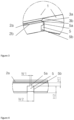
Figure 2 shows a joint of two adjacent floor panels -
Figure 3 shows a joint of two adjacent floor panels from the other direction -
Figure 4 shows a vertical groove -
Figure 5 shows part of the flooring with connected floor panels on the side abutting the ground. - A
floor panel 1 is configured in the form of a rectangular board having at least two joints provided on opposite sides in the form of areceiving element 2 on one side and a connectingelement 3 on the opposite side, the connectingelement 3 and thereceiving element 2 being configured such that, when a flooring is being installed, that is to say, when thefloor panels 1 are being assembled, the connectingelement 3 fits into thereceiving element 2 in a form-locking manner, thus ensuring a tight joint between twoadjacent floor panels 1. - In the preferred embodiment, the
receiving element 2 is configured as arecess 2a and the connectingelement 3 is configured as atongue 3a which fits into therecess 2a in a form-locking manner. - To further stiffen the tight joint against unintentional disassembly of the joint, the
receiving element 2 is provided with anadditional protrusion 2b and the connectingelement 3 is provided with anindentation 3b, wherein upon the installation of the flooring, i.e. assembly offloor panels 1, theprotrusion 2b fits into the indentation 3b. Said configuration of thereceiving element 2 and the connectingelement 3 also allows the joint to be easily opened if necessary, for example in the case where asingle floor panel 1 needs to be replaced. - The
floor panel 1 is provided on its bottom face, that is the face which abuts the floor during installation, with at least onefloor groove 4 in respective longitudinal and transverse directions. - On each of the sides intended for a
receiving element 2, thefloor panel 1 is provided with at least onevertical groove 5 extending from the bottom surface of thefloor panel 1 through thereceiving element 2. - The
vertical groove 5 is formed in its upper portion, i.e. on the side facing the room when installed, in the form of aslot 5a, while it is formed in its bottom portion, i.e. on the side facing the ground when installed, in the form of anextension 5b, the transition from theslot 5a to theextension 5b being continuous. The continuous transition can be implemented in different ways, for example with straight lines or a curve or a combination of both. - The ratio between the width W1 of the
slot 5a and the width W2 of theextension 5b is between 1:1.1 and 1:10. The ratio between the height H1 of theslot 5a and the height H2 of theextension 5b is between 1:1 and 1:50. - Preferably, the width W1 and the height H1 of the
slot 5a should be at least such to easily receive a cutting element of a tool for cutting thefloor panel 1 and to allow adequate positioning of the tool for cutting thefloor panel 1. This allows thefloor panel 1 to be cut straight and square in both the horizontal and vertical directions, so that theindividual floor panels 1 can be quickly and easily adjusted in length and width depending on the floor plan surface. - The
vertical groove 5 is preferably formed axially symmetrically with respect to the vertical axis. - Preferably, the
floor panel 1 has a plurality offloor grooves 4 in the longitudinal and transverse directions, thefloor grooves 4 preferably being equidistantly spaced. - Preferably, the
floor panel 1 is provided with a plurality ofvertical grooves 5, preferably arranged so that theextension 5b of eachvertical groove 5 continues continuously into thecorresponding floor groove 4. - Preferably, the width of the
floor groove 4 is substantially identical to the width W2 of theextension 5b. -
Floor panels 1 are preferably made of polymeric materials having a compressive strength in the range from 50 kPa to 800 kPa, which allow prefabrication by appropriate polymer processing techniques. - The flooring assembly process includes laying the
floor panels 1 on the floor and joining them by means of receivingelements 2 and connectingelements 3, so that a tight joint is made between thefloor panels 1. The assembly process - installation method starts in a corner of a room, wherein thefloor panels 1 are laid in rows, a first row being laid from one wall to the opposite wall, followed by a second row, and so on until the flooring is laid. As thevertical grooves 5 are visible during the installation of thefloor panels 1, it is also possible to precisely offsetindividual floor panels 1, if this is necessary due to the flooring layout. As thevertical grooves 5 continue continuously into thecorresponding floor grooves 4, a continuous arrangement of thefloor grooves 4 across the bottom surface of the flooring is also ensured. - The floor assembly process comprises the following steps:
- placing a
first floor panel 1 in a corner of a room on the floor, wherein thefirst floor panel 1 is placed on the floor so that the two sides provided with a connectingelement 3 face the corresponding walls of the room and the two sides provided with areceiving element 2 andvertical grooves 5 face the room; - placing each
subsequent floor panel 1 so that thefloor grooves 4 of thesubsequent panel 1 are as closely aligned as possible with thefloor grooves 4 of the precedingpanel 1, and joining eachsubsequent floor panel 1 through joining points, wherein the joiningelement 3 of asubsequent floor panel 1 fits into thereceiving element 2 of the precedingfloor panel 1 in a form-locking manner, thereby ensuring a tight joint between the twoadjacent floor panels 1 and a continuous arrangement offloor grooves 4 over the entire bottom surface of the flooring, a first row offloor panels 1 being laid first from one wall to the opposite wall, followed by a second row, and so on until the flooring installation is completed. - If an
individual floor panel 1 is to be adjusted in length and width to the floor plan of the room, thefloor panel 1 is adequately trimmed before the installation and laid in accordance with the installation procedure described above. - Said structure of the
floor panel 1 and the installation method have the following advantages: - the
floor grooves 4 allow impurities, such as pebbles, which remain on the surface of the substrate (floor) on which thefloor panels 1 are laid, to be withdrawn into thefloor grooves 4, thus ensuring the stability and suitable flatness of the laid flooring; - the
vertical grooves 5 allow any debris and particles that may be generated during installation to be pushed into thevertical grooves 5, thus ensuring a tight joint between the two floor panels; - the shape of the
vertical groove 5 with thenarrower slot 5a in the upper part allows precise positioning of the tool for cutting thefloor panels 1 and thus a straight and perpendicular cut of thefloor panel 1 in both the horizontal and vertical directions, thus allowing a high precision of the lengths of thecut panels 1 to be achieved in a quick and easy way; - the shape of the
vertical groove 5 with theextension 5b in the lower portion allows the chips generated at cutting to fall more easily due to the extension and to move away from the cutting area; - the shape of the
vertical groove 5 prevents the cutting tool from tearing thefloor panel 1 at the end and/or at the beginning of the cutting process, making the cutting of thefloor panels 1 precise and fast; - the vertical 5 and
floor grooves 4 allow air to remain trapped in thegrooves - the
floor grooves 4 allow the installation of cables (since thegrooves 4 are continuous), such as power cables, data cables, etc., from one side of the room to the other, in a way that is concealed; in this case, thegrooves 4 act as an installation canal, which, if the function of the room is changed, allows the room to be re-purposed without major interventions in the room; - the configuration of the
floor 4 andvertical grooves 5, namely thevertical grooves 5 continue continuously into thefloor grooves 4, a grid ofgrooves floor panel 1 and cutting the same; - since the
vertical grooves 5 are visible during the installation of the flooring (when laying the floor panels 1) by the defined installation method or system, it is also possible to precisely offsetindividual floor panels 1, if this is necessary due to the layout of the surface on which the floor panels are being installed, while ensuring a continuous arrangement of the canals, i.e. thefloor grooves 4.
Claims (10)
- A floor panel (1) used in a flooring installation system, wherein the floor panel (1) is configured in the form of a rectangular board having at least two joints provided on opposite sides in the form of a receiving element (2) on one side and a connecting element (3) on the opposite side, the connecting element (3) and the receiving element (2) being configured such that, when a flooring is being installed, the connecting element (3) fits into the receiving element (2) in a form-locking manner, characterized in that the floor panel (1) is provided on its bottom face, that is the face which abuts the floor during installation, with at least one floor groove (4) in respective longitudinal and transverse directions, on each of the sides intended for a receiving element (2), the floor panel (1) is provided with at least one vertical groove (5) extending from the bottom surface of the floor panel (1) through the receiving element (2), wherein the vertical groove (5) is formed in its upper portion, i.e. on the side facing the room when installed, in the form of a slot (5a), while it is formed in its bottom portion, i.e. on the side facing the ground when installed, in the form of an extension (5b).
- The floor panel (1) according to claim 1, characterized in that the transition from the slot (5a) to the extension (5b) is implemented in a continuous way with straight lines or a curve or a combination of both.
- The floor panel (1) according to claims 1 and 2, characterized in that the ratio between the width (W1) of the slot (5a) and the width (W2) of the extension (5b) is between 1:1.1 and 1:10.
- The floor panel (1) according to any of the preceding claims, characterized in that the ratio between the height (H1) of the slot (5a) and the height (H2) of the extension (5b) is between 1:1 and 1:50.
- The floor panel (1) according to any of the preceding claims, characterized in that the vertical groove (5) is preferably formed axially symmetrically with respect to the vertical axis.
- The floor panel (1) according to any of the preceding claims, characterized by being provided with a plurality of floor grooves (4) in the longitudinal and transverse directions, the floor grooves (4) preferably being equidistantly spaced.
- The floor panel (1) according to any of the preceding claims, characterized by being provided with a plurality of vertical grooves (5) and said vertical grooves (5) being preferably arranged so that the extension (5b) of each vertical groove (5) continues continuously into the corresponding floor groove (4).
- The floor panel (1) according to any of the preceding claims, characterized in that the width of the floor groove (4) is preferably identical to the width (W2) of the extension (5b).
- The floor panel (1) according to any of the preceding claims, characterized by being made of polymeric materials having a compressive strength in the range from 50 kPa to 800 kPa.
- A floor panel installation method comprising the following steps:- placing a first floor panel (1) in a corner of a room on the floor, wherein the first floor panel (1) is placed on the floor so that the two sides provided with a connecting element (3) face the corresponding walls of the room and the two sides provided with a receiving element (2) and vertical grooves (5) face the room;- placing each subsequent floor panel (1) so that the floor grooves (4) of the subsequent floor panel (1) are as closely aligned as possible with the floor grooves (4) of the preceding floor panel (1), and joining each subsequent floor panel (1) through joining points, wherein the joining element (3) of a subsequent floor panel (1) fits into the receiving element (2) of the preceding floor panel (1) in a form-locking manner, thereby ensuring a tight joint between the two adjacent floor panels (1) and a continuous arrangement of floor grooves (4) over the entire bottom surface of the flooring, a first row of floor panels (1) being laid first from one wall to the opposite wall, followed by a second row, and so on until the flooring installation is completed.
Applications Claiming Priority (1)
| Application Number | Priority Date | Filing Date | Title |
|---|---|---|---|
| SI202200145A SI26412A (en) | 2022-08-29 | 2022-08-29 | Floor panel and floor panel assembly process |
Publications (2)
| Publication Number | Publication Date |
|---|---|
| EP4332322A2 true EP4332322A2 (en) | 2024-03-06 |
| EP4332322A3 EP4332322A3 (en) | 2024-03-13 |
Family
ID=88237888
Family Applications (1)
| Application Number | Title | Priority Date | Filing Date |
|---|---|---|---|
| EP23193654.3A Pending EP4332322A3 (en) | 2022-08-29 | 2023-08-28 | Floor panel and floor panel assembly process |
Country Status (2)
| Country | Link |
|---|---|
| EP (1) | EP4332322A3 (en) |
| SI (1) | SI26412A (en) |
Citations (3)
| Publication number | Priority date | Publication date | Assignee | Title |
|---|---|---|---|---|
| EP1261785A1 (en) | 2000-03-07 | 2002-12-04 | E.F.P. Floor Products Fussböden GmbH | Mechanical connection of panels |
| EP1585867A1 (en) | 2003-01-24 | 2005-10-19 | John Redding | Underwater sediment management |
| EP2718516A1 (en) | 2011-06-06 | 2014-04-16 | Fritz Egger GmbH & Co. OG | Floor panel with a lateral edge having a locking bar |
Family Cites Families (3)
| Publication number | Priority date | Publication date | Assignee | Title |
|---|---|---|---|---|
| DE29716028U1 (en) * | 1997-09-05 | 1997-10-30 | Akzenta Paneele & Profile Gmbh | Laminate covering, especially for floors |
| BR112014000016B1 (en) * | 2011-07-11 | 2020-12-22 | Ceraloc Innovation Ab | mechanical locking system for floor panels |
| JP6139661B2 (en) * | 2012-04-13 | 2017-05-31 | アームストロング ワールド インダストリーズ インコーポレーテッド | Floating floor system, floor panel, and installation method thereof |
-
2022
- 2022-08-29 SI SI202200145A patent/SI26412A/en unknown
-
2023
- 2023-08-28 EP EP23193654.3A patent/EP4332322A3/en active Pending
Patent Citations (3)
| Publication number | Priority date | Publication date | Assignee | Title |
|---|---|---|---|---|
| EP1261785A1 (en) | 2000-03-07 | 2002-12-04 | E.F.P. Floor Products Fussböden GmbH | Mechanical connection of panels |
| EP1585867A1 (en) | 2003-01-24 | 2005-10-19 | John Redding | Underwater sediment management |
| EP2718516A1 (en) | 2011-06-06 | 2014-04-16 | Fritz Egger GmbH & Co. OG | Floor panel with a lateral edge having a locking bar |
Also Published As
| Publication number | Publication date |
|---|---|
| SI26412A (en) | 2024-03-29 |
| EP4332322A3 (en) | 2024-03-13 |
Similar Documents
| Publication | Publication Date | Title |
|---|---|---|
| US10273689B2 (en) | Panel and method for fabricating, installing and utilizing a panel | |
| US4896469A (en) | Prefabricated building panel assembly | |
| EP1907650B1 (en) | Metal finishing tile, production method and related covering | |
| US9725902B1 (en) | Panel and method for fabricating, installing and utilizing a panel | |
| EP4332322A2 (en) | Floor panel and floor panel assembly process | |
| GB2291079A (en) | Insulated building blocks | |
| CA1078576A (en) | Partition wall capable of being dismantled | |
| JPWO2008149543A1 (en) | Baffle mounting frame and formwork method | |
| KR101830354B1 (en) | Block for constructing wall and construction wall thereof | |
| US8667751B2 (en) | Set of elements for constructing a wooden wall and method for using such elements | |
| JP7210470B2 (en) | A flat building element, especially for composing horizontal building structures | |
| KR100438756B1 (en) | Fixer assembly for insulation of building | |
| EP2020471A1 (en) | Dry floor system and method for manufacturing a dry floor system | |
| EP4182513B1 (en) | Multi-layer wall element for building up drywalls as well as drywall comprising the wall element | |
| JP2018115426A (en) | Floor material unit and construction method thereof | |
| JP7329212B2 (en) | Plate material construction tool, plate material construction structure, and plate material construction method | |
| KR200258316Y1 (en) | Fixer assembly for insulation of building | |
| RU2220265C1 (en) | Building block | |
| CA3219494A1 (en) | Interlockable wall reinforcement panel, wall reinforcement assembly and method for wall reinforcement | |
| JP2021161701A (en) | Double floor structure | |
| JP3493997B2 (en) | Floor material construction method | |
| LT5389B (en) | Building blocks | |
| CH718367A2 (en) | Construction panel for building walls. | |
| JP3303657B2 (en) | Construction method and construction structure of building board | |
| JPH11141015A (en) | Plane of structure construction and plane of structure fitting construction |
Legal Events
| Date | Code | Title | Description |
|---|---|---|---|
| PUAI | Public reference made under article 153(3) epc to a published international application that has entered the european phase |
Free format text: ORIGINAL CODE: 0009012 |
|
| STAA | Information on the status of an ep patent application or granted ep patent |
Free format text: STATUS: THE APPLICATION HAS BEEN PUBLISHED |
|
| PUAL | Search report despatched |
Free format text: ORIGINAL CODE: 0009013 |
|
| AK | Designated contracting states |
Kind code of ref document: A2 Designated state(s): AL AT BE BG CH CY CZ DE DK EE ES FI FR GB GR HR HU IE IS IT LI LT LU LV MC ME MK MT NL NO PL PT RO RS SE SI SK SM TR |
|
| AK | Designated contracting states |
Kind code of ref document: A3 Designated state(s): AL AT BE BG CH CY CZ DE DK EE ES FI FR GB GR HR HU IE IS IT LI LT LU LV MC ME MK MT NL NO PL PT RO RS SE SI SK SM TR |
|
| RIC1 | Information provided on ipc code assigned before grant |
Ipc: E04F 15/02 20060101AFI20240206BHEP |