EP4332292A1 - Washing machine door lock module and washing machine - Google Patents
Washing machine door lock module and washing machine Download PDFInfo
- Publication number
- EP4332292A1 EP4332292A1 EP22794669.6A EP22794669A EP4332292A1 EP 4332292 A1 EP4332292 A1 EP 4332292A1 EP 22794669 A EP22794669 A EP 22794669A EP 4332292 A1 EP4332292 A1 EP 4332292A1
- Authority
- EP
- European Patent Office
- Prior art keywords
- door
- positioning
- rod
- washing machine
- unlocking
- Prior art date
- Legal status (The legal status is an assumption and is not a legal conclusion. Google has not performed a legal analysis and makes no representation as to the accuracy of the status listed.)
- Withdrawn
Links
Images




Classifications
-
- D—TEXTILES; PAPER
- D06—TREATMENT OF TEXTILES OR THE LIKE; LAUNDERING; FLEXIBLE MATERIALS NOT OTHERWISE PROVIDED FOR
- D06F—LAUNDERING, DRYING, IRONING, PRESSING OR FOLDING TEXTILE ARTICLES
- D06F39/00—Details of washing machines not specific to a single type of machines covered by groups D06F9/00 - D06F27/00
- D06F39/12—Casings; Tubs
- D06F39/14—Doors or covers; Securing means therefor
-
- D—TEXTILES; PAPER
- D06—TREATMENT OF TEXTILES OR THE LIKE; LAUNDERING; FLEXIBLE MATERIALS NOT OTHERWISE PROVIDED FOR
- D06F—LAUNDERING, DRYING, IRONING, PRESSING OR FOLDING TEXTILE ARTICLES
- D06F37/00—Details specific to washing machines covered by groups D06F21/00 - D06F25/00
- D06F37/42—Safety arrangements, e.g. for stopping rotation of the receptacle upon opening of the casing door
-
- D—TEXTILES; PAPER
- D06—TREATMENT OF TEXTILES OR THE LIKE; LAUNDERING; FLEXIBLE MATERIALS NOT OTHERWISE PROVIDED FOR
- D06F—LAUNDERING, DRYING, IRONING, PRESSING OR FOLDING TEXTILE ARTICLES
- D06F23/00—Washing machines with receptacles, e.g. perforated, having a rotary movement, e.g. oscillatory movement, the receptacle serving both for washing and for centrifugally separating water from the laundry
- D06F23/02—Washing machines with receptacles, e.g. perforated, having a rotary movement, e.g. oscillatory movement, the receptacle serving both for washing and for centrifugally separating water from the laundry and rotating or oscillating about a horizontal axis
-
- D—TEXTILES; PAPER
- D06—TREATMENT OF TEXTILES OR THE LIKE; LAUNDERING; FLEXIBLE MATERIALS NOT OTHERWISE PROVIDED FOR
- D06F—LAUNDERING, DRYING, IRONING, PRESSING OR FOLDING TEXTILE ARTICLES
- D06F37/00—Details specific to washing machines covered by groups D06F21/00 - D06F25/00
- D06F37/30—Driving arrangements
- D06F37/302—Automatic drum positioning
Definitions
- the invention relates to the field of drying household appliances, in particular, to a door locking unit of a washing machine, and also to a washing machine.
- the current washing machine is usually provided with an unlocking unit for unlocking the door, but the unlocking unit only has the function of unlocking, and cannot realize the function of locating the locking position of the washing tub and/or the door. In the process of actually unlocking the door, it should be ensured that the washing tub and/or the door are positioned at a preset position to prevent the rotation of the washing tub from affecting the unlocking process during the unlocking process.
- An objective of the present invention is to provide a positioning and unlocking unit, which can ensure that the washing tub and/or the machine door are locked in a preset position to unlock the door.
- the present invention provides a positioning and unlocking unit for a washing machine, comprises a casing; a positioning rod arranged in the casing, the positioning rod capable of extending out of the casing and correspondingly extending into a positioning hole arranged on a washing tub and/or a machine door; a door opening rod arranged in the casing, the door opening rod capable of extending out of the casing to drive to unlock; and a transmission assembly.
- the positioning rod is extended into the positioning hole for a first movement stroke and then when extending outward for a second movement stroke, the door opening rod is driven to extend to the outside of the casing by the transmission assembly.
- the positioning and unlocking unit for a washing machine can drive the door opening rod to unlock after the positioning rod is inserted in the positioning hole, so it is ensured that the washing tub and/or the machine door is unlocked at the preset locked position.
- the transmission assembly comprises, a first rack arranged on the positioning rod and extending along a movement direction of the positioning rod; a third rack, arranged on the door opening rod and extending along the movement direction of the door opening rod; and a fourth gear assembly, provided with a first meshing surface and a second meshing surface.
- the first meshing surface is engaged and connected the three rack on which the first movement stroke and the second movement stroke are generated, and the second meshing surface is separated from the first rack in the first movement stroke and engaged with the first rack in the second movement stroke.
- the movement directions of the positioning rod and the door opening rod extending outward are perpendicular to each other, and the first rack is perpendicular to the third rack.
- the structure of the first rack and the third rack can achieve the movement of the positioning rod vertical to that of the door opening rod.
- the positioning rod is extended downward and out of the casing, and the first rack is extended in the vertical direction.
- the door opening rod is extended out of the casing in the horizontal direction, and the third rack is extended in the horizontal direction.
- the fourth gear assembly is arranged above the third rack, and under the first rack in the first movement stroke, and the first rack is arranged on the left or right side of the fourth gear assembly.
- the positioning rod is provided with a second rack on which the positioning rod is driven to move downward in a vertical direction, and the second rack is arranged in parallel with the first rack.
- the second rack is engaged and connected with a second gear assembly, and the second gear assembly is engaged and connected with a power assembly for driving movement.
- the power assembly comprises a motor, and an output gear sleeved on an output shaft of the motor.
- the output gear is engaged and connected with a reduction gear set, the final output gear of the reduction gear set is meshed with the second gear assembly.
- a third gear assembly is arranged between the second gear assembly and the third rack, and the third gear assembly is respectively meshed with the second gear assembly and the third rack.
- the specific arrangement of the second gear assembly, the third gear assembly, the reduction gear set and the positioning rod in the housing is as follows.
- the rotating shaft of the second gear assembly is in parallel with the rotating shaft of the motor, and the second gear assembly has a vertical center plane passing through the rotating shaft.
- Both the reduction gear set and the third gear assembly are arranged on the same side relative to the vertical center plane, and the positioning rod is arranged on the other side relative to the vertical center plane.
- a running block is fixed on the positioning rod, and the first rack and the second rack are arranged on the running block.
- the bottom surfaces of the first rack and the second rack are all flush with the bottom surface of the running block.
- a length of the second rack is larger than a length of the first rack; further preferably, the length of the second rack is equal to a total length of the positioning rod extending outward in the first movement stroke and the second movement stroke.
- the length of the first rack is equal to the length of the door opening rod extending outward in the second movement stroke.
- a horizontal distance between the rotation shaft of the fourth gear assembly and the rotation shaft of the third gear assembly is set as L1, and L1 is less than the total length of the door opening rod extending outward in the first running stroke and the second running stroke.
- a vertical distance between the rotation shaft of the second gear assembly and the rotation shaft of the fourth gear assembly is set as L2, and L2 is equal to the length of the positioning rod extending outward in the first movement stroke.
- the present invention has the following beneficial effects compared with the prior art.
- Another object of the present invention is to provide a washing machine door lock detection unit, which can accurately detect the unlocking of the door lock and the positioning of the washing tub and/or the machine door by detecting the position of the positioning rod.
- the invention provides a door lock detection unit for a washing machine, comprising, a positioning and unlocking device in which a positioning rod and a door opening rod are arranged.
- the positioning and unlocking device is configured to operate a positioning movement and a unlocking movement.
- the positioning movement comprises, the positioning rod correspondingly extending into the positioning hole provided on the door and/or the washing tub of the washing machine;
- the unlocking movement comprises, the positioning rod driving the door opening rod to operate to unlock the door.
- a detection device is comprised to be used for detecting the position of the positioning rod, and detecting whether the positioning movement and unlocking movement are completed.
- the door lock detection unit of the present invention can detect the unlocking condition of the door lock and the positioning condition of the washing tub and/or the machine door by detecting the position of the positioning rod.
- the positioning rod moves along the same linear trajectory; and the detection device detects the position of the positioning rod moving in the linear trajectory.
- the positioning rod is extended into the positioning hole along the linear trajectory.
- the unlocking movement the positioning rod inserted into the positioning hole continues to move a outward long the linear trajectory, and drives the door opening rod to operate to unlock the door in outward moving. Since the movement trajectory of the positioning rod is relatively simple and only a linear trajectory, it is more convenient to detect the position of the positioning rod.
- the detection device is a photosensitive detection device
- a light shielding plate is provided on the positioning rod
- a photoelectric panel for emitting light and the photosensitive detection device are disposed at a predetermined position of the linear movement trajectory.
- At least a part of light sources of the photoelectric panel and the photosensitive detection device are fixedly installed on two sides of the light shielding plate opposite to each other.
- the photoelectric panel is configured to emit detection light towards the photosensitive detection device, and the light shielding plate shades the detection light emitted by the photoelectric panel when moving to the corresponding position together with the positioning rod.
- a direction of the detection light emitting from the photoelectric panel to the photosensitive detection device is perpendicular to the movement direction of the positioning rod.
- the photosensitive detection device comprises a first photosensitive detector and a second photosensitive detector.
- the first photosensitive detector is arranged on a position of the positioning rod where the positioning movement is executed and corresponding to the position of the light shading plate.
- the second photosensitive detector is arranged on a position of the positioning rod where the unlocking movement is executed and corresponding to the position of the light shading plate.
- the first photosensitive detector can detect whether the positioning rod completes the movement of the positioning stage, and the second photosensitive detector can correspondingly detect whether the positioning rod completes the movement of the unlocking stage.
- the photoelectric panel is provided with a guide hole being extended along the movement direction of the positioning rod for a certain length.
- the light shading plate is inserted in the guide hole, corresponds to a section of the positioning rod, and moves together with the positioning rod.
- the first photosensitive detector and the second photosensitive detector are respectively arranged one side of the guide hole.
- the movement direction of the light shading plate and the positioning rod is perpendicular to the direction of the detection light emitting from the photoelectric panel to the photosensitive detection device.
- first photosensitive detector and the second photosensitive detector are both provided with control switches, and the control switches are both connected with the motor for providing power for the movement of the door opening rod and the positioning rod. Since the first photosensitive detector and the second photosensitive detector are connected with the motor respectively, the motor can be controlled to turn on the first photosensitive detector and the second photosensitive detector in moving process. That is, the first photosensitive detector and the second photosensitive detector are turned on only during the movement of the positioning rod, to prevent wasting energy.
- the photosensitive detection device is capable of transmitting a position signal.
- the door lock detection unit of the washing machine includes a signal receiving device for receiving the position signal.
- a guide rail groove is provided at the position of the positioning hole of the machine door and/or the washing tub, and the guide rail groove is formed by the positioning hole extending in the movement direction of the positioning rod.
- the positioning rod inserted in the positioning hole is embedded in the guide rail groove to move.
- the bottom of the positioning rod is fixedly provided with a slider
- the guide rail groove is provided with a groove in which the slider is inserted
- a detection device is installed in the groove for detecting whether the slider is inserted into the groove. That is, the door lock detection unit provided of the present invention can also detect whether the positioning rod is moved in proper place through the arrangement of the guide rail groove, the slider and the groove.
- the door lock detection unit of the washing machine includes a door closing detection device for detecting whether the machine door is closed in a proper place.
- the door closing detection device includes a magnet arranged on the machine door, a Hall sensor is installed on the housing and/or the outer tub, and the Hall sensor is used to detect the position of the magnet.
- the Hall sensor is installed at a place where the magnet arranged on the machine door is detected in closing and locking the machine door.
- the magnet arranged on the machine door is detected by the Hall sensor.
- the magnet arranged on the door is not detected by the Hall sensor. It can be detected whether the door locking unit is locked in proper place through the setting of the magnet and the Hall sensor.
- the door locking device comprises a door hook fixed on the machine door, and a lock body corresponding to the position of the door hook, and the machine door is closed in the proper place to make the lock body lock the door hook.
- the present invention has the following beneficial effects compared with the prior art.
- a washing machine of the invention comprises: a washing tub, rotatably arranged in the washing machine; a washing tub door, arranged on the washing tub and being capable of opening and closing the opening of the washing tub; a door locking unit, for locking the washing tub door being closed; and a positioning and unlocking unit, having a positioning structure for locking the washing tub at a set position, and a unlocking structure being used for being driven to unlock the door locking unit by the positioning structure after the washing tub is locked at the set position.
- the washing machine of the invention can realize the positioning of the washing tub during the process of opening and closing the machine door, and can ensure that the washing tub is unlocked after being positioned.
- the positioning and unlocking unit includes a door opening rod and a positioning rod.
- the door locking unit includes a limiting component for keeping the machine door in a locked state.
- the positioning rod is individually extended into the positioning hole arranged on the washing tub and/or the washing tub door, or the positioning rod drives the door opening rod to contact with and trigger the limiting component to move after extending in the positioning hole.
- the door locking unit is fixed on the washing tub door, and the positioning and unlocking unit is correspondingly fixed on the wall of the outer tub.
- a front flange is arranged on the outer tub and corresponds to the position of the washing tub door.
- An unlocking hole for the door opening rod to pass through is provided on the front flange of the outer tub.
- the door opening rod is in contact with the limiting component through the unlocking hole; and a sealing member is arranged at the unlocking hole.
- the door opening rod of the positioning and unlocking unit needs to pass through the unlocking hole on the front flange of the outer tub, and the front flange of the outer tub may come into contact with water, so a seal member can be provided at the unlocking hole for tightness.
- the washing machine comprises a door lock detection unit for detecting whether the door locking unit locks the washing tub door, detecting whether the positioning and unlocking unit locks the washing tub at the set position, and detecting whether the washing tub door is unlocked by the positioning and unlocking unit.
- a control method for the aforementioned washing machine of the invention comprises: controlling the positioning and unlocking unit to lock the washing tub at a set position when the washing tub door needs to be opened, and then the washing tub door being operated to be opened.
- the control method for the washing machine of the invention can ensure that the washing tub is locked at a preset position to open the machine door, prevent danger caused by opening the machine door from happening during the running of the washing machine, and can ensure the normal opening operation of the machine door.
- the door lock detection unit detects whether the washing tub is locked at the set position by the positioning and unlocking unit, the positioning and unlocking unit is controlled to unlock the door locking unit after determining that the washing tub is locked at the set position, and the washing tub door is operated to be opened after the door lock detection unit detects that the positioning and unlocking unit is unlocked.
- the positioning rod of the positioning and unlocking unit is controlled to extend into the positioning hole when the positioning and unlocking unit is controlled to lock the washing tub at the set position.
- the door lock detection unit is controlled to detect the position of the positioning rod when the door lock detection unit detects whether the washing tub is locked at the set position by the positioning and unlocking unit.
- the positioning rod of the door locking unit is controlled to extend into the positioning hole and drive the door opening rod to contact with and trigger the limiting component to move.
- control method for closing the door includes the following steps. After the washing tub door is opened and the laundry are put in, and when the washing tub door needs to be closed, the door lock detection unit is controlled to detect whether the positioning unlocking unit locks the washing tub at the set position. The operation of closing the washing tub door is executed when it is determines that the positioning unlocking unit keeps the washing tub being locked at the set position.
- the door locking unit is controlled to lock the washing tub door, and the door lock detection unit detects whether the washing tub door is locked.
- the positioning and unlocking unit is controlled to release the washing tub from being locked at the set position.
- the door lock detection unit is controlled to detect whether the positioning and unlocking unit releases the washing tub from being locked at the set position, and the washing machine is controlled to run after determining that the washing tub is released from being locked at the set position.
- the door locking detection unit detects whether the positioning rod is extended into the positioning hole.
- the positioning rod of the positioning and unlocking unit is controlled to extend out of the positioning hole.
- the door lock detection unit detects whether the positioning rod extends out of the positioning hole.
- the present invention has the following beneficial effects compared with the prior art.
- Another object of the present invention is to provide a door locking unit of a washing machine, in which the limiting component in the door locking unit of the washing machine has a reasonable structure, so the effect of guiding the rotational movement of the locking portion is achieved.
- a door locking unit of a washing machine in the invention includes, a door hook fixed with a machine door, a locking portion being capable of rotating to hook the door hook, and a limiting component moving to the locking portion hooking with the door hook for limitation.
- a guiding slope is arranged on the limiting component, the locking portion is driven to move to be in contact with the guiding slope of the limiting component, and the guiding slope guides the locking portion to rotate.
- the structural of the limiting component in the door locking unit of the washing machine of the present invention is reasonable, and can guide the locking portion to rotate according to the set trajectory.
- the limiting component is provided with a limiting column with a shape of basically rectangle, and the guiding slope is provided on the limiting column near a top corner of the locking portion.
- the guiding slope is a slope being downward extended from the top of the limiting column, and the guiding slope is used for guiding the locking portion to rotate clockwise.
- a side surface being as a second limiting surface of the limiting column is connected with the guiding slope and close to the locking portion capable of rotating, and a side surface of the locking portion is a third limiting surface corresponding to the second limiting surface.
- the second limiting surface and the third limiting surface are in limited contact with each other.
- a limiting surface for locking the locking portion is also provided on the limiting column. The limiting surface of the locking portion and the guiding slope are arranged on the same limiting column, so that the structure of the limiting component is relatively simple.
- the limiting component has a base perpendicular to the limiting column, and the limiting column and base compose "L"-shaped structure in middle of which there is a space.
- the locking portion being in static is embedded in the space.
- An end surface of the locking portion perpendicular to the rotation shaft abuts against the first limiting surface of the limiting column.
- the door locking unit of the washing machine has a shell, a limiting component is arranged in the shell, and a compression spring is arranged between the shell and the side surface of the limiting component perpendicular to the rotation shaft of the locking portion. The limiting component being in static compresses the compression spring.
- one end of the limiting component is extended to the outside of the shell (3).
- the one end the limiting component being not provided with the compression spring is extended to the outside of the shell.
- the limiting component can be extended to the outside of the shell, so that the limiting component can be activated by other external structures to unlock the door.
- the specific structure of the rotatable locking portion is as follows.
- a support rod is fixed in the shell.
- the locking portion is sleeved on the support rod, and torsion springs are respectively sleeved on the support the rod and on both sides of the locking portion.
- the door hook comprises a hook portion extending into the shell, and the hook portion is provided with a locking hole for hooking the locking portion.
- a guide rail for guiding the hook portion to extend into is arranged in the shell, and the guide rail is extended from the top of the shell corresponding to the door hook toward the interior of the housing.
- the locking portion is set as a "C"-shaped structure with an opening facing to the door hook, and the opening of the locking portion is locked with the locking hole of the door hook.
- the door locking unit for the washing machine further comprises a door manually opening portion embedded in the shell; and the door manually opening portion drives the limiting component to move. By setting the door manually opening portion, the door can be unlocked by pressing the door manually opening portion.
- a first contact surface protruding outward is provided on the limiting component, and the second contact surface of the door manually opening portion is correspondingly set as being inclined outwards and upward from the bottom.
- the first contact surface is in contact with the second contact surface when the door manually opening portion is pressed.
- the shell is provided with a mounting hole for inserting the door manually opening portion, a button is provided on the top of the door manually opening portion, the button is protruded out of the installation hole; and the bottom of the door manually opening portion is provided with a compression spring.
- the button on the door manually opening portion is convenient for pressing, and the compression spring is convenient for reset after pressing.
- the present invention has the following beneficial effects compared with the prior art.
- the present invention provides a washing machine, in which a washing tub for washing laundry is arranged, and a washing tub door 42 is arranged on the washing tub.
- a supporting shell and/or an outer tub is arranged outside the washing tub, and a washing machine door 43 is disposed on the supporting shell and/or the outer tub at a position corresponding to the washing tub door 42 of the washing tub.
- the washing machine of the present invention is provided with a door lock system for locking and unlocking the door.
- the door lock system includes a door locking unit 40 that is used for locking the washing machine door after being closed, and a positioning unlocking unit 41 that is used for unlocking the door locking unit 40 accordingly.
- the positioning and unlocking unit 41 can also position the locking position of the washing tub.
- the structure of the door lock can be applied to the washing machine door 43 and/or the washing tub door 42.
- the door locking unit 40 can be applied to the washing tub door 42, and can also be applied to the washing machine door 43.
- the door locking unit 40 includes a door hook fixed with the washing machine door, and a locking device fixed on the washing tub or on the supporting shell. When the washing machine door is closed, the door hook is correspondingly extended into the locking device and is hooked by the locking device to lock the washing machine door.
- a door hook is provided on the washing tub door 42 and a locking device may be is provided on the washing tub to lock the washing tub door 42.
- a door hook is provided on the washing machine door 43 and a locking device is provided on the supporting shell to lock the washing machine door 43.
- the positioning and unlocking unit 41 has a positioning rod 22.
- the positioning rod 22 is capable of penetrating through a positioning hole to realize the position.
- the positioning and unlocking unit 41 also has a door opening rod 23.
- the door opening rod 23 can activate to disengage the door hook from the locking device of the door locking unit after the desired movement, to realize the unlocking of the door. That is, the positioning and unlocking unit 41 of the present invention can realize the positioning function and the unlocking function.
- the positioning and unlocking unit 41 can be set on the washing tub corresponding to the door locking device on the washing tub door 42, and the positioning hole can be set on the front flange of the washing tub, so that the position where the washing tub is locked together the washing tub door 42 is positioned.
- the positioning and unlocking unit 41 can be arranged on the supporting shell.
- the door locking system of the washing machine of the present invention can enable the washing tub door 42 and the washing machine door 43 to be opened or locked separately.
- the door locking system can also realize to position the position where the washing tub is locked together the door.
- the present invention also provides a method for controlling the inner door and outer door with respect to the above-mentioned door locking system, and the method of the present invention can reasonably control to open or close the inner door and outer door.
- the door locking unit 40 for locking and unlocking a machine door.
- the door locking unit 40 includes a door hook 1 fixed with the machine door.
- the door hook 1 is capable of moving with the machine door during the process of closing the machine door.
- the door locking unit 40 also includes a lock body for locking the door hook 1.
- the lock body has a shell. When the machine door is closed, the door hook 1 is extended into the lock body and is locked by the lock body, thereby locking the machine door.
- the lock body includes a locking portion 4 being rotatable.
- the locking portion 4 can hook the door hook 1 when rotating in one direction, and can be disengaged from the door hook 1 when the rotating in the opposite direction.
- the lock body also includes a limiting component 2 for limiting the movement state of the locking portion 4.
- the limiting component 2 abuts against the locking portion 4 to keep the locking portion 4 being in stationary, thereby ensuring that the locking portion 4 continuously and stably locks the door hook 1.
- the limiting component 2 can be moved to release the limit on the locking portion 4.
- the locking portion 4 rotates in the opposite direction, and the locking portion is disengaged from the door hook 1 to unlock the machine door.
- the lock body includes a shell 3 in which a locking portion 4 is rotatably arranged.
- a support rod 10 is arranged in the shell 3, and both ends of the support rod 10 are fixed on the shell 3 of the lock body.
- the locking portion 4 being capable of rotating is sleeved on the support rod 10, and the locking portion 4 is fixed in the shell 3 by the support rod 10.
- the limiting component 2 has a structure similar to an "L" shape. When the locking device does not start to move, the locking portion 4 is embedded in the space of the "L"-shaped structure of the limiting component.
- the "L"-shaped structure is composed of a limiting column 44 being vertical and a horizontal base vertical to the limiting column.
- the locking portion 4 When the locking portion 4 is embedded in the space of the "L"-shaped structure, the surface 5 of the locking portion 4 being perpendicular to the rotation axis abuts against a first limiting surface 6 of the limiting column 44. That is, at the beginning of the movement, the locking portion 4 and the limiting block 2 are engaged with each other to limit the position.
- a compression spring is arranged between the shell 3 and the side of the limiting component 2 that is perpendicular to the rotation shaft of the locking portion 4.
- the limiting component 2 compresses the compression spring when it is stationary at the beginning of movement. That is, when the locking portion 4 is in a stationary state, the limiting component 2 is limited by the locking portion 4 being in stationary state, and the limiting component 2 compresses the compression spring.
- a guiding slope 7 is provided on the limiting column 44 at the edge position corresponding to the locking portion 4 being capable of rotating.
- the locking portion 4 being rotating can be in contact with the guiding slope 7 of the limiting component 2 being in moving.
- the locking portion 4 rotates according to a set trajectory under the guiding action of the guiding slope 7 in contact therewith.
- the guiding slope 7 is a slope being downward extended from the top of the limiting column 44 and being gradually oblique to the shell, so that the locking portion 4 in contact with the guiding slope 7 is easily guided to rotate clockwise by the guiding slope 7.
- the locking portion 4 being in rotating clockwise is easy to hook the door hook 1, and the locking portion 4 being hooked in the door hook 1 abuts against the limiting component 2 for limitation. That is, the locking portion 4 is locked by the limiting component 2.
- Figure 3 shows the specific structure that the limiting column 44 abuts the locking portion 4 hooking the door hook 1.
- the limiting column 44 has a second limiting surface 8 parallel to the rotation axis of the locking portion 4, the locking portion 4 has a third limiting surface 9 parallel to the rotation axis, and the second limiting surface 8 of limiting column 44 is contact with the third limiting surface 9 of the locking portion 4 after being rotated. That is, the limiting column 44 can lock the locking portion 4 hooking the door hook 1, thereby locking the machine door.
- the second limiting surface 8 of the limiting column 44 is connected with the guiding slope 7, and the second limiting surface 8 is on the side close to the locking portion 4 being capable of rotating.
- the locking portion 4 rotates, and is guided by the guiding slope 7 to be contact with the second limiting surface 8 of the limiting column 44 for limitation, so the limiting component 2 can lock the locking portion 4.
- the second limiting surface 8 does not limit the position of the third limiting surface 9, and the locking portion 4 rotates in the opposite direction under the action of the torsion spring 11, so that the locking portion 4 is disengaged from the door hook 1.
- portion of the limiting component 2 is disposed outside the shell 3, so that other structures can push the limiting component 2.
- the compression spring provided on the limiting component 2 is in a compressing state.
- other structures push the portion of the limiting component 2 located outside the shell 3, and the limiting component 2 is driven to move for unlocking under the action of the compression spring.
- the door hook 1 is separated from the locking portion, and the machine door is unlocked.
- the end of the limiting component 2 without the compression spring is in the outside of the shell 3, and the portion extending to the outside of the shell 3 is used for being driven the limiting component 2 to move by the other structure.
- the specific structure of the door hook 1 is shown in the figure 1 .
- the door hook 1 includes a fixing portion 15 fixed to the machine door.
- the fixing portion 15 can be provided with screw holes and bolt holes, and the door hook 1 is fixed on the door by screw connection.
- other fixing structures such as snaps may also be arranged on the fixing portion 15 to fix the door hook 1 on the machine door.
- the door hook 1 is provided with screw holes.
- the machine door is provided with an installation groove for installing the door hook 1, the fixing portion 15 of the door hook 1 can be embedded in the installation groove, and the fixing portion 15 of the door hook 1 is fixed in the installation groove through screw connection.
- the fixing portion 15 on the door hook 1 is disposed outside the shell 3 and is fixed on the machine door.
- the door hook 1 further includes a hook portion 12 connected with the fixing portion 15.
- the hook portion 12 extends toward the interior of the shell 3 from the position connected to the fixing portion 15, and a part of the hook portion 12 in the interior of the shell 3 is provided with a locking hole 13.
- the door hook 1 moves with the machine door, and the hook portion 12 of the door hook 1 is contacted with the locking structure.
- the hook portion 12 triggers the locking portion 4 to the rotate, and a part of the locking portion 4 is inserted into the locking hole 13.
- the door hook is connected with the locking portion 4 in insertion mode to lock the door hook, so that the machine door is locked.
- the door hook 1 needs to move according to a preset trajectory, so that the locking hole 13 on the door hook 1 is engaged with the locking portion 4, and the machine door is locked. Therefore, in order to better define the running trajectory of the door hook 1, a guide rail 14 for guiding the door hook 1 to run is provided in the shell 3 of the locking structure.
- the guide rail 14 is extended from the top of the shell 3 corresponding to the door hook 1 toward the interior of the shell 3.
- the hook portion 12 of the door hook 1 is inserted in the guide rail 14.
- the hook portion 12 runs in the direction set by the guide rail 14. As described above, the door can be guaranteed to be properly locked and unlocked.
- the door hook 1 when the machine door is closed, the door hook 1 is inserted into the locking portion 4, the door hook 1 is contacted the locking portion 4, and drives the locking portion 4 to be inserted into the locking hole 13 on the door hook 1.
- the locking portion 4 is set as a "C"-shaped structure with an opening 16 facing the locking hole 13, and the opening 16 of the "C"-shaped structure can be inserted into the locking hole 13 of the door hook 1.
- the locking portion 4 is rotated by being contacted with the door hook 1. During the rotation, the locking hole 13 of the door hook 1 is inserted into the opening 16 of the "C"-shaped structure.
- the limiting component 2 moves to a position where the "C"-shaped structure abuts against the limiting component 2, so that the door hook 1 remains being locked by the "C"-shaped structure, thereby the machine door is locked.
- the second limiting surface 8 of the limiting component 2 abuts on the third limiting surface 9 of the locking portion 4 for limitation.
- the third limiting surface 9 is the surface of "C"-shaped structure of the locking portion 4 opposite to the opening 16.
- the locking structure also needs to be provided with a torsion spring 11, so that the locking portion 4 of the locking structure rotates in unlocking, and the "C"-shaped structure of the locking portion 4 is disengaged from the door hook 1.
- the torsion spring 11 is sleeved on the support rod 10, and is arranged on both end surfaces of the locking portion 4 that are perpendicular to the rotation axis.
- the structure of the limiting component 2 in the door locking unit 40 provided in this embodiment is reasonable.
- the limiting component 2 includes a plurality of surfaces which can be in contact with the locking portion 4. Through the arrangement of the surfaces, the locking portion 4 is limited by the limiting component 2 to not rotate in stationary state. After the locking portion 4 is driven to move, it is guided by the limiting component 2 to rotate according to the set trajectory, and the locking portion 4 hooks the door hook 1 and is locked by the limiting component 2.
- the structure of the door locking unit 40 provided in this embodiment is reasonable, so that the machine door can be locked and unlocked by pushing the part of the limiting component 2 located outside the shell 3. The machine door can be locked and unlocked only by the movement of the limiting component 2, and the operation is relatively simple.
- This embodiment provides a door locking unit 40 on the basis of Embodiment 1.
- the door locking unit 40 has the door hook 1, the locking portion 4 and the limiting component 2 as described above.
- the door hook 1 can be interlocked with the locking portion 4 to lock the machine door, and the limiting component 2 is used to keep the door hook 1 stably interlocking with the locking portion 4, or to disengage the door hook 1 from the locking portion 4.
- the difference between the door locking unit 40 of the present embodiment and the door locking unit 40 of Embodiment 1 is that, the door locking unit 40 of the present embodiment is provided with a door manually opening portion 17 by which the movement of the limiting component 2 is manually controlled, so that the door locking unit 40 can be manually controlled to unlock the machine door.
- the shell 3 of the door locking unit 40 is provided with a mounting hole into which the door manually opening portion 17 is inserted.
- the top of the door manually opening portion 17 is provided with a button 20 being protruded, which is convenient for pressing the door manually opening portion 17 downward.
- the button 20 protrudes from the surface of the shell 3 of the door locking unit 40, so that the button 20 can be pressed when it is required.
- the door manually opening portion 17 inserted into the shell 3 has a surface being contacted with the surface of the limiting device. The surfaces in contact with each other are respectively the first contact surface 18 of the limiting component 2 and the second contact surface 19 of the door manually opening portion 17.
- the limiting component 2 is provided with a contact portion that can be in contact with the door manually opening portion 17 being in embedded.
- the contact portion is disposed on the side of the limiting component 2 close to the door manually opening portion 17, corresponding to the door manually opening portion.
- the first contact surface 18 is set on the contact portion, and the first contact surface 18 is set as a curved surface being protruded outward.
- the second contact surface 19 of the door manually opening portion 17 is correspondingly set as an inclined surface gradually inclining outward from the bottom. The door manually opening portion 17 moves downward through pressing the button 20.
- the second contact surface 19 pushes the first contact surface 18, that is, the limiting block 2 is driven to move.
- the compression spring located at the end of the limiting component 2 is in a compressed state when the door is locked. Once the limiting component 2 is driven to move, the compression spring drives the limiting component 2 to disengage from the locking structure, thereby making the door hook 1 disengage from the locking structure to complete the unlocking of the door.
- a compression spring is also arranged on the door manually opening portion, for example, the compression spring can be arranged at the bottom of the door manually opening portion.
- the door manually opening portion After pressing the button 20 of the door manually opening portion for unlocking, the door manually opening portion is reset under the action of the compression spring.
- the second contact surface 19 and the first contact surface 18 cooperate to limit the position, and the second contact surface 19 is finally stuck by the first contact surface 18. It is ensured that the door manually opening portion 17 is reset to the preset position, and the door manually opening portion can be used normally next time.
- the door manually opening portion 17 is arranged inside the locking device, it can be ensured that the door can be manually unlocked under any circumstances.
- This embodiment provides a positioning and unlocking unit 41 of a machine door for unlocking the machine door and positioning the locking position.
- the positioning and unlocking unit 41 is suitable for all washing machine doors, and is especially suitable for unlocking the washing tub door 42 disposed on the washing tub.
- the positioning and unlocking unit 41 as shown in figure 5 , has a door opening rod 23 and a positioning rod 22.
- the positioning rod 22 is used for positioning the locking position
- the door opening rod 23 is used for unlocking the machine door.
- both the positioning rod 22 and the door opening rod 23 remain stationary inside the positioning and unlocking unit 41.
- the positioning and unlocking unit 41 performs positioning and unlocking, it is subject to two movement stages.
- the first stage is the positioning stage.
- the positioning rod 22 extends to the outside of the positioning and unlocking unit 41, and is inserted into the positioning hole for positioning the positioning rod 22.
- the positioning rod 22 passes through the positioning hole to realize to position the washing tub.
- the positioning hole can be set on the washing tub door 42 and/or the washing tub.
- the washing machine stops running the washing tub and the washing tub door 42 are positioned at a preset position. At this time, the position of the positioning hole corresponds that of the positioning rod 22.
- the washing tub and/or the washing tub door 42 can be locked in a preset position.
- the positioning hole can be provided on the front flange of the outer tub. Once the washing machine stops running, the washing tub door 42 and the washing tub are positioned at the preset position. At this time, the positioning hole on the front flange of the washing tub corresponds to the positioning rod 22, and the positioning rod 22 is controlled to move downward to the positioning hole. Thereby the washing tub and/or the washing tub door 42 can be positioned at the locking position.
- a guide groove can also be provided at the positioning hole of the front flange of the washing tub, and the positioning rod 22 can be embedded in the guide groove to accurately define the movement trajectory of the positioning rod 22.
- a sliding block can also be provided on the positioning rod 22, and a groove in which the sliding block is inserted is provided on the guide groove. After the positioning rod 22 completes the movement for positioning, the sliding block can be controlled to be embedded in the groove. In this way, by arranging a detection device in the guide groove and/or groove, the detection device can detect whether the positioning is completed.
- the positioning rod 22 and/or the sliding block move to the preset position in the guide groove and/or groove, and the detection device detects the positioning rod 22 and/or the sliding block.
- the positioning and unlocking unit 41 in the embodiment cannot only use the positioning rod 22 to position the washing tub and the machine door, and but also can use the detection device to detect whether the positioning is successfully completed.
- the door opening rod 23 moves in the horizontal direction to the outside of the positioning and unlocking unit 41. That is, the door opening rod 23 moves toward the door locking unit 40, so that the door opening rod 23 triggers the door locking unit 40 to unlock.
- the positioning rod 22 is inserted into the positioning hole, and the door opening rod 23 extends toward the door locking unit 40 for a certain distance. So, when the unlocking operation is performed later, the door opening rod 23 can continue to extend outward and extend to a position where being contact with the door locking unit 40, to trigger door locking unit to unlock.
- the door opening rod 23 moves in the horizontal direction and the positioning rod 22 moves in the vertical direction as an example.
- the desired movement trajectories of the door opening rod 23 and the positioning rod 22 can also be adjusted.
- the movement directions of the door opening rod 23 and the positioning rod 22 are perpendicular to each other. After the installation direction of the positioning and unlocking unit 41 is changed, the door opening rod 23 can also be moved in the vertical direction, and the positioning rod 22 can be moved in the horizontal direction.
- the positioning unlocking unit 41 is in the unlocking stage.
- the door opening rod 23 continues to move toward the outside of the positioning and unlocking unit 41 in the horizontal direction, and the door opening rod 23 contacts and triggers the door locking unit 40 arranged on the machine door, so that the door locking unit 40 is unlocked.
- the positioning and unlocking unit 41 of this embodiment is first in the positioning stage and then in the unlocking stage during operation, so that the washing tub and the machine door are locked at the preset positions before unlocking, and the washing tub and the machine door are locked at the preset positions in the unlocking process of the machine door.
- the structures of the positioning and unlocking unit 41 such as the positioning rod 22 of this embodiment can also be used to ensure that the washing tub and the machine door are locked at preset positions. That is, the positioning and unlocking unit 41 in this embodiment can enable the washing tub to be at a preset position during the process of opening and closing the machine door of the washing machine.
- the positioning unlocking unit 41 includes a first drive system for providing power for the movement in the positioning stage.
- the first drive system includes a motor 24.
- the motor 24 includes an output shaft that outputs rotational motion.
- An output gear 25 is sleeved on the output shaft, and the output gear 25 is meshed with a first gear 35.
- a first gear assembly 26 is mainly used for decelerating and transmitting the rotational motion, and the first gear assembly 26 is a reduction gear set.
- the first gear assembly 26 includes the first gear 35 with a larger number of teeth and a second gear 36 with a smaller number of teeth.
- the first gear 35 and the second gear 36 are coaxially arranged.
- the output gear 25 is meshed with the first gear 35 with a larger number of teeth, and the rotation of the first gear 35 can drive the second gear 36 to rotate. That is, through the connection between the output gear 25 and the first gear 35 of the first gear assembly 26, the rotational movement output by the motor 24 is decelerated.
- the first gear assembly 26 is meshed with the second gear assembly 27.
- the second gear 36 of the first gear assembly 26 is meshed with the second gear assembly 27.
- the second gear assembly 27 provides power to drive the door opening rod 23 and the positioning rod 22 to respectively move in the desired direction.
- the second gear assembly 27 drives the positioning rod 22 to move downward, and the third gear assembly 31 drives the door opening rod 23 to move outward for a distance. Since the second gear assembly 27 provides power for the positioning rod 22 and the door opening rod 23, the second gear assembly 27 needs to bear a relatively large force, so the strength of the second gear assembly 27 needs to be enhanced.
- a reinforcing rib is arranged on the second gear assembly 27.
- the purpose of setting the third gear assembly 31 is to make the door opening rod 23 is extended out for a certain distance during the unlocking stage.
- the positioning rod 22 continues to drive the door opening rod 23 to extend outwards, so the total length of the door opening rod 23 extending out is ensured, and the door opening rod 23 must be able to contact with the door locking unit to trigger the unlocking.
- the first gear assembly 26, the second gear assembly 27, and the third gear assembly 31 are all fixed gears whose rotation shafts are fixed.
- the positioning and unlocking unit 41 further includes a running block 28.
- the running block 28 is embedded in the positioning rod 22, and the positioning rod 22 can move with the running block 28.
- a second rack 29 is provided on the running block 28 at a position corresponding to the second gear assembly 27, and the second rack 29 is engaged with the second gear assembly 27.
- the second gear assembly 27 can drive the second rack 29 to move, and further drives the running block 28 and the positioning rod 22 to move, and finally the positioning rod 22 realizes the positioning movement.
- the second gear assembly 27 is connected with the second rack 29 to provide power for the movement of the positioning rod 22 in the positioning stage.
- the positioning and unlocking unit 41 has a casing 21.
- the first gear assembly 26, the second gear assembly 27, and the third gear assembly 31 are all arranged in the casing 21, and both the positioning rod 22 and the door opening rod 23 can be retracted in the casing 21, so it results that more structures are in the casing 21.
- the rotation shaft of the second gear assembly 27 is arranged parallel to the rotation shaft of the motor 24.
- the second gear assembly 27 has a vertical center plane passing through the rotation shaft, and the first gear assembly 26 and the third gear assembly 31 are arranged on the same side relative to the vertical center plane.
- the positioning rod 22 is arranged on the other side relative to the vertical center plane.
- the positioning rod 22 and the third gear assembly 31 are arranged on the two sides of the second gear assembly 27 respectively, so that the movements of the positioning rod 22 and the door opening rod 23 are not interfered with each other.
- the first gear assembly 26, the second gear assembly 27, and the third gear assembly 31 are connected in sequence, and there is a height difference between the first gear assembly 26 and the third gear assembly 31, so the first gear assembly 26 and the third gear assembly 31 are provided on the same side.
- the positioning and unlocking unit 41 can simultaneously control the door opening rod 23 and the positioning rod 22 to move.
- the motor 24 first drives the first gear assembly 26 to rotate at a reduced speed, and then the first gear assembly 26 drives the second gear assembly 27 to rotate.
- the rotation of the second gear assembly 27 drives a third rack 30 and the third gear assembly 31 to rotate.
- the positioning rod 22 is driven to move downward, and simultaneously the door opening rod 23 to move toward the outside of the positioning and unlocking unit 41 in the horizontal direction.
- the positioning and unlocking unit 41 is provided with a fourth gear assembly 33 which can push the door opening rod 23 to move further outward.
- the fourth gear assembly 33 is also a fixed gear with a fixed rotating shaft.
- the fourth gear assembly 33 is arranged above the third rack 30 of the door opening rod 23, and the fourth gear assembly 33 is always contact with the third rack 30 of the door opening rod 23. Once the fourth gear assembly 33 starts to rotate, the first meshing surface on the fourth gear assembly 33 is in meshing connection with the third rack 30.
- the first rack 32 is set on the surface of the running block 28 corresponding to the fourth gear assembly 33, and the first rack 32 continues to descend with the running block 28 during the positioning stage.
- the running block 28 and the first rack 32 thereon move to a preset position.
- the fourth gear assembly 33 is set at a position where it can be engaged and connected with the first rack 32 moving to the preset position.
- the first rack 32 of the running block 28 reaches the position where it engages with the fourth gear assembly 33, to drive the fourth gear assembly 33 to rotate, and then the fourth gear assembly 33 pushes the door opening rod 23 to perform an unlocking movement.
- the door opening rod 23 again extends toward the outside of the positioning and unlocking unit 41 and triggers the door locking unit 40, so that the door locking unit 40 completes the unlocking action.
- the vertical distance between the rotation shaft of the fourth gear assembly 33 and the door opening rod 23 is equal to the vertical distance between the rotation shaft of the third gear assembly 31 and the door opening rod 23. In this way, the force on the door opening rod 23 can be relatively uniform, and the door opening rod 23 can be ensured to move in the horizontal direction.
- a rectangular protrusion 34 is provided on the running block 28.
- a second rack 29 is provided on the side of the protrusion 34 corresponding to the second gear assembly 27.
- the first rack 32 is provided on the other side of the protrusion 34 parallel with the side on which the second rack 29 is arranged. A.
- the positioning rod 22 can be driven by the second gear assembly 27, and the positioning rod 22 can also drive the fourth gear assembly 33 to move, thereby saving space in the casing 21.
- the lower end of the first rack 32 and the lower end of the second rack 29 are flush with the lower end of the running block 28, so that the shape of the protrusion 34 is relatively simple. Since the positioning rod 22 is driven to extend downward by the second rack 29 during the whole movement of the positioning stage and the unlocking stage, the length of the second rack 29 is sufficient to allow the positioning rod 22 to complete the whole movement of the positioning stage and the unlocking stage. That is, the length of the second rack 29 is greater than or equal to the total length of the positioning rod 22 extending outward in the positioning stage and the unlocking stage.
- the length of the second rack 29 is equal to the total length of the positioning rod 22 extending outward during the movement of the positioning stage and the movement of the unlocking stage.
- L5 is a length for which it goes through that the positioning rod 22 moves downward in the positioning stage.
- L4 is a length for which it goes through that the positioning rod 22 moves downward in the unlocking stage. So the length of the second rack 29 is equal to L4 plus L5.
- the first rack 32 drives the door opening rod 23 to move in the unlocking stage, the length of the first rack 32 satisfies the movement of the door opening rod 23 in the unlocking stage, so the length of the first rack 32 is greater than or equal to the length extending outward of the door opening rod 23 in the unlocking stage.
- the length of the second rack 29 is larger than the length of the first rack 32.
- both the fourth gear assembly 33 and the third gear assembly 31 drive the third rack 30 on the door opening rod 23 to move.
- the horizontal distance between the rotation shaft of the fourth gear assembly 33 and the rotation shaft of the third gear assembly 31 is L1
- the third rack 30 starts to move leftward from the position in contact with the third gear assembly 31. If L 1 is greater than the total length extending outwards of the door opening rod 23 in the positioning stage and the unlocking stage, the third rack 30 may not be in meshing contact with the fourth gear assembly 33. So L1 is smaller than the total length extending outwards of the door opening rod 23 in the positioning stage and the unlocking stage.
- the second rack 29 of the positioning rod 22 begins to mesh with the second gear assembly 27 at the position of the rotating shaft
- the first rack 32 of the positioning rod 22 begins to mesh with the fourth gear assembly 33 at the position of the rotating shaft.
- the vertical distance between the rotation shaft of the second gear assembly 27 and the rotation shaft of the fourth gear assembly 33 is L2
- the length of L2 is greater than or equal to the length extending outward of the positioning rod 22 in the positioning stage, to ensure the positioning rod 22 completes the movement in the positioning stage. Therefore, in order to save the space in the housing of the positioning and unlocking unit, preferably, the length of L2 is equal to the length extending outward of the positioning rod 22 in the positioning stage.
- the positioning and unlocking unit 41 in this embodiment includes the door opening rod 23 and the positioning rod 22.
- the structure in the positioning and unlocking unit 41 enables the positioning rod 22 to position the locking position of the washing tub, and enables the door opening rod 23 to realize to unlock the door.
- the positioning rod 22 inserting into the positioning hole drives the door opening rod 23 to perform the unlocking movement, so that the washing tub and/or the machine door are locked in the preset position before unlocking.
- the door lock detection unit of the washing machine in this embodiment can be used to detect the state of the machine door lock.
- the door lock may include the door locking unit 40 in Embodiment 1 and Embodiment 2, and the positioning and unlocking unit 41 in Embodiment 3.
- the door lock detection unit of the washing machine includes a door opening rod 23 for triggering to unlock the door lock, and a positioning rod 22 for positioning the door lock and/or the washing tub.
- the door opening rod 23 and the positioning rod 22 can be linked with each other.
- the door lock detection unit of the washing machine also includes a detection device for detecting the positioning rod 22 and judging the state of the door lock.
- the positioning rod 22 realizes the positioning of the washing tub and/or the door, and then the positioning rod 22 drives the door opening rod 23 to move. Therefore, when the door opening rod 23 does not perform unlocking the machine door, or the door opening rod 23 has finished unlocking the machine door, the positioning rod 22 also has different movement states and/or moves to different positions. So the positioning rod 22 can be detected by the detection device to determine the movement state of the door lock.
- the door opening rod 23 In the process of actually unlocking the machine door, the door opening rod 23 needs to be contacted and trigger the door locking unit 40 as described in Embodiments 1 and 2.
- the detection device is not arranged between the door opening rod 23 and the door locking unit 40. As a result, it is difficult to detect the door opening rod 23.
- the door opening rod 23 is interlocked with the positioning rods 22, such as the positioning and unlocking unit 41 in Embodiment 3, as described above, the movement of the positioning rod 22 can be detected to detect whether the door lock is unlocked.
- the door opening rod 23 and the positioning rod 22 go through different movement stages in the process of unlocking and positioning, and different stages respectively correspond to different states of the door lock. Therefore, the state of the door lock can be determined by detecting the movement stage of the positioning rod 22.
- the positioning and unlocking unit 41 in Embodiment 3 the positioning and unlocking unit 41 can control the positioning rod 22 and the door opening rod 23 to perform the movements in the positioning stage and the unlocking stage.
- the positioning rod 22 is inserted into the positioning hole to achieve positioning.
- the door opening rod 23 is extended out of the positioning and unlocking device.
- the door lock When the positioning rod 22 and the door opening rod 23 complete the movement of the positioning stage, the door lock is in a locked state, and the washing tub and the machine door are in a state of being locked in the preset position.
- the door opening rod 23 and the positioning rod 22 complete the unlocking stage the door lock is in an unlocked state, and the washing tub and the machine door are still locked in the preset position.
- the position of the positioning rod 22 changes constantly in the positioning stage and the unlocking stage, so the detection device can detect the position of the positioning rod 22 to determine the movement stage of the positioning rod 22, and then to determine the above state of the machine door and the door lock.
- the positioning and unlocking unit 41 can also be different from the positioning and unlocking unit 41 in Embodiment 3. As long as the door opening rod 23 is linked with the positioning rod 22, and the positioning rod 22 is in different positions in different movement stages, it can be determined the state of the door lock and/or the machine door according to the position of the positioning rod 22.
- the positioning rod 22 moves along the same linear trajectory during the positioning stage and the unlocking stage, and the detection device can detect the movement position of the positioning rod 22 in the linear trajectory.
- the positioning rod 22 moves in a linear trajectory, so that the movement trajectory of the positioning rod 22 is relatively simple.
- the trajectory of the movement position of the positioning rod 22 is easily detected, and the detection device is easily arranged.
- the positioning and unlocking unit 41 in Embodiment 3 can realize that the positioning rod 22 moves along the same linear trajectory in the positioning stage and the unlocking stage.
- the detection device is arranged in the linear movement trajectory of the positioning rod 22.
- the detection device may be an image acquisition device or an electrical signal detection device.
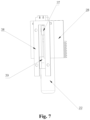
- a photosensitive detection device As shown in figure 7 , a light shielding plate 37 is arranged on the positioning rod 22, and a photosensitive detection device is arranged at the linear movement trajectory of the positioning rod 22.
- a photoelectric panel 38 for emitting light is disposed at a position corresponding to the linear movement trajectory of the positioning rod 22.
- the light shading plate 37 is fixed on the positioning rod 22, and the positioning rod 22 drives the light shading plate 37 to move.
- the light shading plate 37 shades the light in different positions, and the photosensitive detection device detects the different positions shading light, so the position of the positioning rod 22 can be positioned.
- part of the light sources of the photoelectric panel 38 and the photosensitive detection device are arranged on both sides of the light shading plate 37, so that part of the light emitted by the photoelectric plate 38 to the photosensitive detection device is shaded by the light shading plate 37.
- the light shading plate 37 is provided on the running block 28 fixed on the positioning rod 22.
- a guide hole 39 is provided on the photoelectric panel 38, and the light shading plate 37 can be inserted into the guide hole 39 correspondingly and run along the direction defined by the guide hole 39, so that the movement of the light shading plate 37 can be limited.
- the photosensitive detection device is arranged along the guide hole 39, so that it can be ensured that the photosensitive detection device detects that the light is shaded.
- the photosensitive detection device includes a first photosensitive detector and a second photosensitive detector.
- the first photosensitive detector is arranged at the position of the positioning rod 22 where the positioning stage is executed and corresponding to the position of the light shading plate 37.
- the second photosensitive detector is arranged at the position of the positioning rod 22 where the unlocking stage is executed and corresponding to the position of the light shading plate 37.
- Both the first photosensitive detector and the second photosensitive detector are arranged on the photoelectric plate 38. In this way, when the first photosensitive detector detects that the light is shaded, the positioning rod 22 completes the movement of the positioning stage. When the second photosensitive detector detects that the light is shaded, the positioning rod 22 completes the movement of the unlocking stage.
- Either the first photosensitive detector or the second photosensitive detector is composed of a detector sensitive to light.
- a control switch may be provided in both the first photosensitive detector and the second photosensitive detector, and the control switch is connected with the motor 24 that provides energy for the movement of the door opening rod 23 and the positioning rod 22.
- the first photosensitive detector and the second photosensitive detector can be controlled to work when the motor 24 starts to run, so as to reduce energy consumption and prolong the life of the photosensitive detectors.
- All the photosensitive detectors can transmit position signals.
- the door lock detection unit of the washing machine also includes a signal receiving device for receiving the position signals. The door lock detection unit of the washing machine can determine the state of the door lock according to the position signal sent by the photosensitive detector.
- the washing tub is provided with a positioning hole for the positioning rod 22 to be inserted in.
- a guide rail groove is set at the position of the positioning hole, and the positioning rod 22 inserted into the positioning hole is in the guide rail groove to move.
- the bottom of the positioning rod 22 is fixedly provided with a slider.
- the guide rail groove is provided with a groove in which the slider is inserted.
- a detection device is installed in the groove, and the detection device can detect whether the slider is inserted into the groove. After the positioning rod 22 completes all movements of the positioning stage and the unlocking stage, the slider on the positioning rod 22 is inserted in the groove, so the detection device disposed in the groove can be used to detect whether the positioning rod 22 moves to the proper place.
- This embodiment also provides a locking detection device for detecting whether the door is locked in proper place.
- the locking detection device includes a magnet arranged on the machine door, and a Hall sensor is arranged on the washing tub at a corresponding position for detecting the position of the magnet.
- the magnet on the machine door reaches the preset position, and the Hall sensor correspondingly detects the magnet to determine that the machine door is locked in proper place.
- washing tub door 42 Since the washing tub door 42 needs to rotate together with the washing tub, the washing tub door 42 cannot be controlled to automatically close by the electric signal.
- a door lock device is arranged on the washing tub door 42 as described in Embodiments 1 and 2, so the washing tub door 42 is locked under the action of closing the door. Therefore, when the washing tub door 42 is manually closed and locked, there is a situation that the machine door is not locked in proper place.
- the above mentioned magnet and Hall sensor can be used to detect whether the machine door is locked in proper place.
- the door lock device in Embodiments 1 and 2 has the door hook 1 and the locking portion 4 as described above.
- the locking portion 4 When the locking portion 4 is not locked, the rotatable locking portion 4 generates force on the door hook 1.
- the machine door fixedly connected with the door hook 1 cannot be driven to stay in the locking position under the action of the door hook 1, the corresponding magnet is not in the preset position, and the Hall sensor cannot detect the magnet.
- the door lock detection unit in this embodiment can accurately determine the state of the door lock by detecting the position of the positioning rod 22.
- the door lock detection unit further includes a locking detection device for detecting whether the machine door is accurately locked. That is, the door lock detection unit in this embodiment can comprehensively detect the door locking process, unlocking process, and positioning process.
- the washing machine includes the positioning and unlocking unit 41 as described in Embodiment 3, and the door locking unit 40 as described in Embodiment 1 or Embodiment 2.
- the positioning and unlocking unit 41 is disposed at a position corresponding to the door locking unit 40, and the positioning and unlocking unit 41 is contacted and cooperated with the door locking unit 40 to complete the unlocking of the machine door.
- the door opening rod 23 of the positioning and unlocking unit 41 is corresponded to the limiting component 2 extending to the outside of the housing 3 of the door locking unit 40.
- the door opening rod 23 automatically moves in the unlocking stage, to drive the limiting component 2 to perform the unlocking movement, and the movement of unlocking the machine door is completed.
- the installation position and structure of the door opening rod 23 in the positioning and unlocking unit 41 can be adjusted, so that the moving direction of the door opening rod 23 can be adjusted.
- the movement direction of the door opening rod 23 in this embodiment is consistent with the axial direction of the limiting component 2, that is, the door opening rod 23 pushes the limiting component 2 to move along the axial direction of the limiting component 2.
- the door opening rod 23 of the positioning and unlocking unit 41 can also be adjusted as moving in a direction perpendicular to the axial direction of the limiting component 2. That is, the door opening rod 23 pushes the side of the limiting component 2 to drive the limiting component 2, and other structures remain unchanged. The machine door can be unlocked.
- the washing machine has a washing tub, and a washing tub door 42 is arranged on the washing tub.
- the washing tub door 42 needs to rotate together with the washing tub. Therefore, as mentioned above, the washing tub door 42 cannot be controlled to be automatically closed by electric signal. Therefore, the door locking unit 40 as described in Embodiments 1 and 2 can be arranged on the washing tub door 42, so that the washing tub door 42 can be locked by the action of closing the washing tub door 42.
- the positioning and unlocking unit 41 may be fixed on the outer tub and/or the washing machine shell, and correspond to a position of the door locking unit 40.
- the door locking unit 40 is fixed on the washing tub door 42, and the positioning and unlocking unit 41 is fixed on the outer tub.
- the door opening rod 23 In order that the door opening rod 23 is in contact with the limiting component 2, the door opening rod 23 passes through the front flange of the outer tub. Therefore, an unlocking hole for the door opening rod 23 to pass through is provided on the front flange of the outer tub. Since the front flange of the outer tub may be exposed to water, a sealing member is preferably provided at the unlocking hole in order to ensure the sealing performance.
- the washing machine in this embodiment further includes the door lock detection unit of the washing machine as described in Embodiment 5.
- the door lock detection unit can detect whether to lock the machine door by the door locking unit 40, and can also detect whether to unlock and position the machine door by the positioning and unlocking unit 41.
- This embodiment provides a control method of the washing machine on the basis of the above mentioned embodiments.
- the washing tub door 42 is arranged on the washing tub, and rotates together with the washing tub during the washing process.
- the washing tub door 42 is provided with the door locking unit 40 as Embodiments 1 and 2.
- a washing tub door 42 is correspondingly provided on the washing tub, and a washing machine door 43 is provided on the outer tub and/or a shell of the washing machine corresponding to the position of the washing tub door 42.
- the washing tub door 42 and the washing machine door 43 can be opened and closed independently.
- This embodiment is especially suitable for a washing machine having only one washing tub inside.
- the control method of the washing machine in this embodiment reasonably sets the operations to be performed by the washing tub door 42 and the washing machine door 43 when opening and closing the doors, so as to ensure the normal operation of opening and closing the double doors.
- the control method of this embodiment includes, detecting whether the washing machine stops running before opening and closing the double doors.
- the washing machine stops running the washing tub is locked.
- the washing machine needs to perform the following other programs, such as the washing program.
- the washing tub starts the next operation from the set locking position, so it is detected whether the washing tub is locked at the preset locking position.
- the detection device on the washing tub is used for detecting whether the washing tub is locked.
- the positioning and unlocking unit 40 is controlled to lock the washing tub at the set position.
- the positioning rod 22 of the positioning and unlocking unit 41 is controlled to complete the movement of the positioning stage as described in Embodiment 3, and then the operation of opening the washing tub door is executed.
- the door lock detection unit detects whether the washing tub is locked at the set position by the positioning and unlocking unit 41. Specifically, the door lock detection unit described as in Embodiment 4 is used for detecting the position of the positioning rod 22, and it is determined whether the positioning rod 22 is inserted into the positioning hole to lock the washing tub at the preset position.
- the positioning and unlocking unit 41 is controlled to unlock the door locking unit 40.
- the door lock detection unit detects that the positioning and unlocking unit 41 completes the unlocking, and the washing tub door to be opened. Specifically, when the positioning and unlocking unit 41 unlocks the door locking unit 40, the positioning rod 22 of the positioning and unlocking unit 41 is controlled to complete the movement of the unlocking stage as described in the third embodiment. And when the door lock detection unit detects whether to unlock, as described in Embodiment 4, the door lock detection unit detects whether the unlock is completed by detecting the position of the positioning rod 22.
- the washing tub door is opened and the laundry is put in.
- the door lock detection unit is controlled to detect whether the positioning unlocking unit 41 still locks the washing tub at the set position.
- the operation of closing the washing tub door is executed.
- the door lock detection unit needs to detect the specific position of the positioning rod 22 to determine whether the positioning rod 22 remains inserted into the positioning hole, and then determine whether the washing tub remains locked in a preset position.
- the door locking unit 40 When the machine door is closed, the door locking unit 40 is controlled to lock the washing tub door, and the door lock detection unit detects whether the washing tub door is locked. Specifically, as described in Embodiments 1 and 2, the door locking unit 40 locks the washing tub door under the action of closing the door. The door lock detection unit can detect whether the washing tub door is locked, as the locking detection device described in Embodiment 4.
- the positioning and unlocking unit 41 is controlled to release the washing tub from being locked at the set position. Specifically, as described in Embodiment 3, the motor 24 of the positioning and unlocking unit 41 rotates reversely, to drive the positioning rod 22 to extract out of the position hole and release the washing tub from being locked.
- the door lock detection unit is controlled to detect whether the positioning unlocking unit 41 releases the washing tub from being locked at the set position. Specifically, the door lock detection unit detects the position of the positioning rod 22, and determines whether there is the contact to limit on the washing tub being locked at the set position in determining the positioning rod 22 to be extended out of the positioning hole. After determining that the limitation on the washing tub being locked in the set position is released, the washing machine is allowed to run, so that the washing tub can rotate to execute the subsequent operations.
- the washing machine generally has a washing tub door 42 located on the washing tub located inside, and a washing machine door 43 located on the outer tub and/or the shell of the washing machine located outside.
- the washing tub door 42 is controlled to keep locked first in the operation of opening the washing machine door 43. So, in opening the washing machine door 43, it is avoided that the washing tub door 42 moves to cause the inner and outer double doors to collide.
- the washing tub door 42 is controlled to be locked first, and the washing machine door 43 is controlled to be unlocked after detecting that the washing tub door 42 is successfully locked, and then the washing machine door 43 is opened.
- the specific control method is: controlling the washing tub door 42 to be unlocked after detecting that the washing machine door 43 is opened.
- the door locking unit 40 and the positioning unlocking unit 41 are provided on the washing tub door 42, the washing tub door 42 can be locked and unlocked when the washing tub is locked at a preset position. That is, the washing tub door 42 can be kept locked during the opening of the washing machine door 43, and be unlocked after the washing machine door 43 is opened.
- the operation of opening the door includes the following steps:
- the washing machine is not used until the laundry is fed into the washing machine again and the door is closed.
- the washing tub is locked at the preset locking position, so that the washing tub can start to run from the preset locking position when the washing machine needs to run again. It is convenient for the washing machine to run normally the washing program. That is, after the operation of opening the double doors is completed and before the operation of closing the double doors is performed, the washing tub is kept locked at the preset locking position.
- the washing tub door 42 and the washing machine door 43 are closed in sequence. After closing the washing tub door 42, the washing tub door 42 is locked, and it is detected whether the washing tub door 42 is locked at a preset position.
- the door locking unit 40 is arranged on the washing tub door 42. Once the washing tub door 42 is properly closed, the washing tub door 42 can be locked by the door locking unit 40. In addition, it can also be detected whether the washing tub door 42 is closed and locked at the proper position through the magnet arranged on the washing tub door 42 as described above. In the above control method, it can be ensured that the washing tub door 42 is closed at a proper position by detecting whether the washing tub door 42 is locked at a preset position.
- the control method in this embodiment is set reasonably.
- the washing tub door 42 is locked after being closed, so that the washing tub door 42 is not affected when the washing machine door 43 is closed.
- the close of the washing machine door 43 is operated only after it is determined that the washing tub door 42 is locked at the preset locking position, so that the washing machine door 43 is closed after the washing tub door 42 is properly closed.
- the washing machine door 43 is locked after closing the washing machine door 43.
- the washing machine can start executing other programs such as the washing program.
- the washing tub needs to perform a desired movement in executing the following programs by the washing machine, so the washing tub is required to be unlocked.
- the inner and outer double doors are kept locked after being closed, so as to prevent the washing machine door 43 from being opened in the operation of the washing machine to affect the normal operation of the washing machine.
- the positioning and unlocking unit 41 in the above mentioned embodiment, the locking and unlocking of the washing tub can be realized by using the positioning and unlocking unit 41.
- the washing tub is unlocked and the washing tub door 42 is locked by the control method.
- the operation of closing the door includes the following steps:
Landscapes
- Engineering & Computer Science (AREA)
- Textile Engineering (AREA)
- Main Body Construction Of Washing Machines And Laundry Dryers (AREA)
Abstract
Description
- The invention relates to the field of drying household appliances, in particular, to a door locking unit of a washing machine, and also to a washing machine.
- The current washing machine is usually provided with an unlocking unit for unlocking the door, but the unlocking unit only has the function of unlocking, and cannot realize the function of locating the locking position of the washing tub and/or the door. In the process of actually unlocking the door, it should be ensured that the washing tub and/or the door are positioned at a preset position to prevent the rotation of the washing tub from affecting the unlocking process during the unlocking process.
- Therefore, it is currently needed to provide with an unlocking unit with positioning function for a washing machine, which can ensure that the washing tub and/or the door are locked in the preset locking position before the unlocking operation is performed.
- In view of the above problems, the present invention is proposed.
- An objective of the present invention is to provide a positioning and unlocking unit, which can ensure that the washing tub and/or the machine door are locked in a preset position to unlock the door.
- The present invention provides a positioning and unlocking unit for a washing machine, comprises a casing; a positioning rod arranged in the casing, the positioning rod capable of extending out of the casing and correspondingly extending into a positioning hole arranged on a washing tub and/or a machine door; a door opening rod arranged in the casing, the door opening rod capable of extending out of the casing to drive to unlock; and a transmission assembly. After the positioning rod is extended into the positioning hole for a first movement stroke and then when extending outward for a second movement stroke, the door opening rod is driven to extend to the outside of the casing by the transmission assembly. The positioning and unlocking unit for a washing machine can drive the door opening rod to unlock after the positioning rod is inserted in the positioning hole, so it is ensured that the washing tub and/or the machine door is unlocked at the preset locked position.
- Further, the structure of the transmission assembly is as follows. The transmission assembly comprises, a first rack arranged on the positioning rod and extending along a movement direction of the positioning rod; a third rack, arranged on the door opening rod and extending along the movement direction of the door opening rod; and a fourth gear assembly, provided with a first meshing surface and a second meshing surface. The first meshing surface is engaged and connected the three rack on which the first movement stroke and the second movement stroke are generated, and the second meshing surface is separated from the first rack in the first movement stroke and engaged with the first rack in the second movement stroke.
- Further, the movement directions of the positioning rod and the door opening rod extending outward are perpendicular to each other, and the first rack is perpendicular to the third rack. The structure of the first rack and the third rack can achieve the movement of the positioning rod vertical to that of the door opening rod.
- Further, the specific structures of the positioning rod, the door opening rod, and the fourth gear assembly are set as follows. The positioning rod is extended downward and out of the casing, and the first rack is extended in the vertical direction. The door opening rod is extended out of the casing in the horizontal direction, and the third rack is extended in the horizontal direction. The fourth gear assembly is arranged above the third rack, and under the first rack in the first movement stroke, and the first rack is arranged on the left or right side of the fourth gear assembly.
- Further, the specific structure of driving the positioning rod to move is as follows. The positioning rod is provided with a second rack on which the positioning rod is driven to move downward in a vertical direction, and the second rack is arranged in parallel with the first rack. The second rack is engaged and connected with a second gear assembly, and the second gear assembly is engaged and connected with a power assembly for driving movement.
- Further, the specific structure of the power assembly is as follows. The power assembly comprises a motor, and an output gear sleeved on an output shaft of the motor. The output gear is engaged and connected with a reduction gear set, the final output gear of the reduction gear set is meshed with the second gear assembly.
- Further, a third gear assembly is arranged between the second gear assembly and the third rack, and the third gear assembly is respectively meshed with the second gear assembly and the third rack. By the arrangement of the third gear assembly, in the first movement stroke, the door opening rod can be extended outward for a distance.
- Further, the specific arrangement of the second gear assembly, the third gear assembly, the reduction gear set and the positioning rod in the housing is as follows. The rotating shaft of the second gear assembly is in parallel with the rotating shaft of the motor, and the second gear assembly has a vertical center plane passing through the rotating shaft. Both the reduction gear set and the third gear assembly are arranged on the same side relative to the vertical center plane, and the positioning rod is arranged on the other side relative to the vertical center plane.
- Further, a running block is fixed on the positioning rod, and the first rack and the second rack are arranged on the running block. The bottom surfaces of the first rack and the second rack are all flush with the bottom surface of the running block. Preferably, a length of the second rack is larger than a length of the first rack; further preferably, the length of the second rack is equal to a total length of the positioning rod extending outward in the first movement stroke and the second movement stroke. The length of the first rack is equal to the length of the door opening rod extending outward in the second movement stroke.
- Further, a horizontal distance between the rotation shaft of the fourth gear assembly and the rotation shaft of the third gear assembly is set as L1, and L1 is less than the total length of the door opening rod extending outward in the first running stroke and the second running stroke. Preferably, a vertical distance between the rotation shaft of the second gear assembly and the rotation shaft of the fourth gear assembly is set as L2, and L2 is equal to the length of the positioning rod extending outward in the first movement stroke.
- Adopting the above-mentioned technical scheme, the present invention has the following beneficial effects compared with the prior art.
- 1) The positioning and unlocking unit of the present invention can not only unlock the door lock, but also position the washing tub and/or the machine door. Through the structure of the positioning and unlocking unit, the machine door is unlocked after the washing tub and/or the machine door is controlled to be positioned by the positioning rod. Thus, it can be ensured that the washing tub and/or the machine door are positioned at a preset position during the unlocking process.
- 2) For the positioning and unlocking unit of the present invention, the movements of the door opening rod and the positioning rod are in two stages, that is, the movement of the positioning stage and the unlocking stage, through the driving device arranged inside. The structure on the positioning rod is reasonably arranged, so that the positioning rod can drive the door opening rod to perform the unlocking movement after the positioning rod completes the movement of the positioning stage.
- 3) The internal structure of the positioning and unlocking unit of the present invention is reasonably arranged, so that the movement of all gear assemblies and the positioning rod are not affected each other.
- 4) Through the reasonable arrangement of the running block of the present invention, the first rack and the second rack are simultaneously arranged on the protrusion, so that the running block can be connected with the second gear assembly and the fourth gear assembly respectively. The third gear assembly and the fourth gear assembly are arranged on the proper positions, so that the force on the door opening rod can be relatively uniform, and the door opening rod can be ensured to move in the horizontal direction.
- 5) In the present invention, the lengths of the first rack and the second rack are set reasonably. so the positioning rod and the door opening rod is ensured to do the desired movement, and the first rack and the second rack are set shorter to avoid waste. The arrangement of the second gear assembly, the third gear assembly and the fourth gear assembly is reasonable, which can save space.
- Another object of the present invention is to provide a washing machine door lock detection unit, which can accurately detect the unlocking of the door lock and the positioning of the washing tub and/or the machine door by detecting the position of the positioning rod.
- The invention provides a door lock detection unit for a washing machine, comprising, a positioning and unlocking device in which a positioning rod and a door opening rod are arranged. The positioning and unlocking device is configured to operate a positioning movement and a unlocking movement. The positioning movement comprises, the positioning rod correspondingly extending into the positioning hole provided on the door and/or the washing tub of the washing machine; the unlocking movement comprises, the positioning rod driving the door opening rod to operate to unlock the door. A detection device is comprised to be used for detecting the position of the positioning rod, and detecting whether the positioning movement and unlocking movement are completed. The door lock detection unit of the present invention can detect the unlocking condition of the door lock and the positioning condition of the washing tub and/or the machine door by detecting the position of the positioning rod.
- Further, in the positioning movement and the unlocking movement, the positioning rod moves along the same linear trajectory; and the detection device detects the position of the positioning rod moving in the linear trajectory. Preferably, in the positioning movement, the positioning rod is extended into the positioning hole along the linear trajectory. In the unlocking movement, the positioning rod inserted into the positioning hole continues to move a outward long the linear trajectory, and drives the door opening rod to operate to unlock the door in outward moving. Since the movement trajectory of the positioning rod is relatively simple and only a linear trajectory, it is more convenient to detect the position of the positioning rod.
- Further, the specific structure of the detection device is as follows. The detection device is a photosensitive detection device, a light shielding plate is provided on the positioning rod, and a photoelectric panel for emitting light and the photosensitive detection device are disposed at a predetermined position of the linear movement trajectory. At least a part of light sources of the photoelectric panel and the photosensitive detection device are fixedly installed on two sides of the light shielding plate opposite to each other. The photoelectric panel is configured to emit detection light towards the photosensitive detection device, and the light shielding plate shades the detection light emitted by the photoelectric panel when moving to the corresponding position together with the positioning rod. Preferably, a direction of the detection light emitting from the photoelectric panel to the photosensitive detection device is perpendicular to the movement direction of the positioning rod.
- Further, the photosensitive detection device comprises a first photosensitive detector and a second photosensitive detector. The first photosensitive detector is arranged on a position of the positioning rod where the positioning movement is executed and corresponding to the position of the light shading plate. The second photosensitive detector is arranged on a position of the positioning rod where the unlocking movement is executed and corresponding to the position of the light shading plate. The first photosensitive detector can detect whether the positioning rod completes the movement of the positioning stage, and the second photosensitive detector can correspondingly detect whether the positioning rod completes the movement of the unlocking stage.
- Further, the photoelectric panel is provided with a guide hole being extended along the movement direction of the positioning rod for a certain length. The light shading plate is inserted in the guide hole, corresponds to a section of the positioning rod, and moves together with the positioning rod. The first photosensitive detector and the second photosensitive detector are respectively arranged one side of the guide hole. Preferably, the movement direction of the light shading plate and the positioning rod is perpendicular to the direction of the detection light emitting from the photoelectric panel to the photosensitive detection device. Through the setting of the guide hole, the movement direction of the light shading plate is defined, and can ensure that the light shading plate can correspondingly shade the light sources at the first photosensitive detector and the second photosensitive detector during the movement with the positioning rod.
- Further, the first photosensitive detector and the second photosensitive detector are both provided with control switches, and the control switches are both connected with the motor for providing power for the movement of the door opening rod and the positioning rod. Since the first photosensitive detector and the second photosensitive detector are connected with the motor respectively, the motor can be controlled to turn on the first photosensitive detector and the second photosensitive detector in moving process. That is, the first photosensitive detector and the second photosensitive detector are turned on only during the movement of the positioning rod, to prevent wasting energy.
- Further, the photosensitive detection device is capable of transmitting a position signal. The door lock detection unit of the washing machine includes a signal receiving device for receiving the position signal.
- Further, a guide rail groove is provided at the position of the positioning hole of the machine door and/or the washing tub, and the guide rail groove is formed by the positioning hole extending in the movement direction of the positioning rod. The positioning rod inserted in the positioning hole is embedded in the guide rail groove to move. The bottom of the positioning rod is fixedly provided with a slider, the guide rail groove is provided with a groove in which the slider is inserted, and a detection device is installed in the groove for detecting whether the slider is inserted into the groove. That is, the door lock detection unit provided of the present invention can also detect whether the positioning rod is moved in proper place through the arrangement of the guide rail groove, the slider and the groove.
- Further, the door lock detection unit of the washing machine includes a door closing detection device for detecting whether the machine door is closed in a proper place. The door closing detection device includes a magnet arranged on the machine door, a Hall sensor is installed on the housing and/or the outer tub, and the Hall sensor is used to detect the position of the magnet. The Hall sensor is installed at a place where the magnet arranged on the machine door is detected in closing and locking the machine door. Preferably, when the machine door is closed and locked in the proper place, the magnet arranged on the machine door is detected by the Hall sensor. When the machine door is not closed and locked in the proper place, the magnet arranged on the door is not detected by the Hall sensor. It can be detected whether the door locking unit is locked in proper place through the setting of the magnet and the Hall sensor.
- Further, a door locking device is provided on the washing machine. The door locking device comprises a door hook fixed on the machine door, and a lock body corresponding to the position of the door hook, and the machine door is closed in the proper place to make the lock body lock the door hook.
- Adopting the above-mentioned technical solutions, the present invention has the following beneficial effects compared with the prior art.
- 1) The door lock detection unit for a washing machine of the invention can realize the connection between the positioning rod and the door opening rod. The unlocking condition of the door opening rod and the positioning condition of the positioning rod are detected by detecting the position of the positioning rod. That is, only one door lock detection unit can comprehensively detects the unlocking and positioning.
- 2) During the unlocking process of the positioning rod of the invention, the movement trajectory is relatively simple, which is convenient for detecting the position of the positioning rod. That is, the door lock detection unit of the washing machine provided of the present invention can facilitate the rapid detection of the door lock state.
- 3) In the invention, the position of the positioning rod can accurately detected by the photosensitive detection device. In addition, the photosensitive detection device of the invention works only when the motor is running, that is, when the positioning rod starts to move. So it is avoided to waste energy and prolong the life of the photosensitive detection device.
- 4) Through the arrangement of the guide rail groove, the slider, the groove and the detection device in the invention, it is detected whether the positioning rod is positioned in proper place by detecting whether the slider on the positioning rod is embedded in the groove. So it is detected whether the positioning rod is extended into the correct place in the positioning hole.
- 5) In the invention, a magnet is arranged on the machine door and a Hall sensor is arranged at the corresponding position of the washing tub. The magnet is detected by the Hall sensor, so it can be accurately determined whether the machine door is locked in proper place.
- Another object of the present invention is to provide a washing machine. It can ensured that the washing tub can be unlocked after being locked in a preset position, and can realize the washing tub is positioned during the process of opening and closing the machine door. Another object of the present invention is to provide a control method for a washing machine. The washing tub is locked during the process of closing the machine door.
- A washing machine of the invention, comprises: a washing tub, rotatably arranged in the washing machine; a washing tub door, arranged on the washing tub and being capable of opening and closing the opening of the washing tub; a door locking unit, for locking the washing tub door being closed; and a positioning and unlocking unit, having a positioning structure for locking the washing tub at a set position, and a unlocking structure being used for being driven to unlock the door locking unit by the positioning structure after the washing tub is locked at the set position. The washing machine of the invention can realize the positioning of the washing tub during the process of opening and closing the machine door, and can ensure that the washing tub is unlocked after being positioned.
- Further, the contact relationship between the positioning and unlocking unit and the door locking unit is as follows. The positioning and unlocking unit includes a door opening rod and a positioning rod. The door locking unit includes a limiting component for keeping the machine door in a locked state. The positioning rod is individually extended into the positioning hole arranged on the washing tub and/or the washing tub door, or the positioning rod drives the door opening rod to contact with and trigger the limiting component to move after extending in the positioning hole.
- Further, the specific arrangements of the door locking unit and the positioning unlocking unit are as follows. The door locking unit is fixed on the washing tub door, and the positioning and unlocking unit is correspondingly fixed on the wall of the outer tub.
- Further, a front flange is arranged on the outer tub and corresponds to the position of the washing tub door. An unlocking hole for the door opening rod to pass through is provided on the front flange of the outer tub. The door opening rod is in contact with the limiting component through the unlocking hole; and a sealing member is arranged at the unlocking hole. During the unlocking process, the door opening rod of the positioning and unlocking unit needs to pass through the unlocking hole on the front flange of the outer tub, and the front flange of the outer tub may come into contact with water, so a seal member can be provided at the unlocking hole for tightness.
- Further, the washing machine comprises a door lock detection unit for detecting whether the door locking unit locks the washing tub door, detecting whether the positioning and unlocking unit locks the washing tub at the set position, and detecting whether the washing tub door is unlocked by the positioning and unlocking unit.
- A control method for the aforementioned washing machine of the invention, comprises: controlling the positioning and unlocking unit to lock the washing tub at a set position when the washing tub door needs to be opened, and then the washing tub door being operated to be opened. The control method for the washing machine of the invention can ensure that the washing tub is locked at a preset position to open the machine door, prevent danger caused by opening the machine door from happening during the running of the washing machine, and can ensure the normal opening operation of the machine door.
- Further, the door lock detection unit detects whether the washing tub is locked at the set position by the positioning and unlocking unit, the positioning and unlocking unit is controlled to unlock the door locking unit after determining that the washing tub is locked at the set position, and the washing tub door is operated to be opened after the door lock detection unit detects that the positioning and unlocking unit is unlocked.
- Further, the specific operations of opening the washing tub door include the following steps. The positioning rod of the positioning and unlocking unit is controlled to extend into the positioning hole when the positioning and unlocking unit is controlled to lock the washing tub at the set position. The door lock detection unit is controlled to detect the position of the positioning rod when the door lock detection unit detects whether the washing tub is locked at the set position by the positioning and unlocking unit. When the positioning and unlocking unit is controlled to unlock the door locking unit, the positioning rod of the door locking unit is controlled to extend into the positioning hole and drive the door opening rod to contact with and trigger the limiting component to move.
- Further, the control method for closing the door includes the following steps. After the washing tub door is opened and the laundry are put in, and when the washing tub door needs to be closed, the door lock detection unit is controlled to detect whether the positioning unlocking unit locks the washing tub at the set position. The operation of closing the washing tub door is executed when it is determines that the positioning unlocking unit keeps the washing tub being locked at the set position. When the machine door is closed, the door locking unit is controlled to lock the washing tub door, and the door lock detection unit detects whether the washing tub door is locked. After it is determined that the washing tub door is locked, the positioning and unlocking unit is controlled to release the washing tub from being locked at the set position. The door lock detection unit is controlled to detect whether the positioning and unlocking unit releases the washing tub from being locked at the set position, and the washing machine is controlled to run after determining that the washing tub is released from being locked at the set position.
- Further, when the door locking detection unit is controlled to detect whether the positioning and unlocking unit keeps the washing tub being locked at the set position, the door locking detection unit detects whether the positioning rod is extended into the positioning hole.
- When the positioning and unlocking unit is controlled to release the washing tub from being locked at the set position, the positioning rod of the positioning and unlocking unit is controlled to extend out of the positioning hole. When the door locking detection unit is controlled to detect whether the positioning and unlocking unit releases the washing tub from being locked at the set position, the door lock detection unit detects whether the positioning rod extends out of the positioning hole.
- Adopting the above-mentioned technical solution, the present invention has the following beneficial effects compared with the prior art.
- 1) The washing machine of the present invention has a door locking unit that can be triggered to lock by the action of closing the door, and the door locking unit is more suitable for being arranged on the washing tub door of the washing tub, so that the washing tub door rotating with the washing tub does not need to be controlled by an electric signal.
- 2) The positioning and unlocking unit in the washing machine of the present invention is reasonably set. The washing tub door can be locked at a preset position, and the unlocking operation is performed after the washing tub is locked at the preset position.
- 3) In the washing machine door system of the present invention, the door locking unit and the positioning and unlocking unit are arranged at reasonable positions. The positioning and unlocking unit is arranged on the outer tub to avoid affecting the normal operation of the washing tub inside. A door lock detection unit in the present invention can comprehensively detect the locking of the washing tub, the condition of locking the washing tub door by the door locking unit, and the unlocking of the positioning and unlocking unit.
- 4) The installation positions of the positioning and unlocking unit and the door locking unit of the washing machine of the present invention are reasonably set, so as to prevent the positioning and unlocking unit from affecting the normal operation of the washing machine. A seal member is provided at the position of the front flange of the outer tub through which the door opening rod of the positioning and unlocking unit needs to pass, so as to ensure the tightness.
- 5) By adapting the controlling method for a washing machine of the present invention, the washing tub is locked at the preset position during the process of opening and closing the machine door, so as to ensure the normal operation of opening and closing the door. And the washing tub can be kept at the preset locking position after the machine door is opened and closed. So when the washing tub is performed to be in washing program, the washing tub starts to run from the locked position.
- 6) By adapting the controlling method for controlling the machine door of the invention, the operations of the washing tub door and the washing machine door are respectively performed when opening and closing the door, so as to ensure the normal opening and closing of the door.
- Another object of the present invention is to provide a door locking unit of a washing machine, in which the limiting component in the door locking unit of the washing machine has a reasonable structure, so the effect of guiding the rotational movement of the locking portion is achieved.
- A door locking unit of a washing machine in the invention, includes, a door hook fixed with a machine door, a locking portion being capable of rotating to hook the door hook, and a limiting component moving to the locking portion hooking with the door hook for limitation. A guiding slope is arranged on the limiting component, the locking portion is driven to move to be in contact with the guiding slope of the limiting component, and the guiding slope guides the locking portion to rotate. The structural of the limiting component in the door locking unit of the washing machine of the present invention is reasonable, and can guide the locking portion to rotate according to the set trajectory.
- Further, the specific structure of the guiding slope is as follows. The limiting component is provided with a limiting column with a shape of basically rectangle, and the guiding slope is provided on the limiting column near a top corner of the locking portion. The guiding slope is a slope being downward extended from the top of the limiting column, and the guiding slope is used for guiding the locking portion to rotate clockwise.
- Further, a side surface being as a second limiting surface of the limiting column is connected with the guiding slope and close to the locking portion capable of rotating, and a side surface of the locking portion is a third limiting surface corresponding to the second limiting surface. In a process that the locking portion rotates clockwise and the limiting component moves in a straight line to approach the locking portion, the second limiting surface and the third limiting surface are in limited contact with each other. A limiting surface for locking the locking portion is also provided on the limiting column. The limiting surface of the locking portion and the guiding slope are arranged on the same limiting column, so that the structure of the limiting component is relatively simple.
- Further, the limiting component has a base perpendicular to the limiting column, and the limiting column and base compose "L"-shaped structure in middle of which there is a space. The locking portion being in static is embedded in the space. An end surface of the locking portion perpendicular to the rotation shaft abuts against the first limiting surface of the limiting column. The door locking unit of the washing machine has a shell, a limiting component is arranged in the shell, and a compression spring is arranged between the shell and the side surface of the limiting component perpendicular to the rotation shaft of the locking portion. The limiting component being in static compresses the compression spring.
- Further, one end of the limiting component is extended to the outside of the shell (3). Preferably, the one end the limiting component being not provided with the compression spring is extended to the outside of the shell. The limiting component can be extended to the outside of the shell, so that the limiting component can be activated by other external structures to unlock the door.
- Further, the specific structure of the rotatable locking portion is as follows. A support rod is fixed in the shell. The locking portion is sleeved on the support rod, and torsion springs are respectively sleeved on the support the rod and on both sides of the locking portion.
- Further, the specific structure of the cooperation between the door hook and the locking portion is as follows. The door hook comprises a hook portion extending into the shell, and the hook portion is provided with a locking hole for hooking the locking portion. A guide rail for guiding the hook portion to extend into is arranged in the shell, and the guide rail is extended from the top of the shell corresponding to the door hook toward the interior of the housing. The locking portion is set as a "C"-shaped structure with an opening facing to the door hook, and the opening of the locking portion is locked with the locking hole of the door hook.
- Further, the door locking unit for the washing machine further comprises a door manually opening portion embedded in the shell; and the door manually opening portion drives the limiting component to move. By setting the door manually opening portion, the door can be unlocked by pressing the door manually opening portion.
- Further, the specific cooperation between the door manually opening portion and the limiting component is as follows. A first contact surface protruding outward is provided on the limiting component, and the second contact surface of the door manually opening portion is correspondingly set as being inclined outwards and upward from the bottom. The first contact surface is in contact with the second contact surface when the door manually opening portion is pressed.
- Further, the shell is provided with a mounting hole for inserting the door manually opening portion, a button is provided on the top of the door manually opening portion, the button is protruded out of the installation hole; and the bottom of the door manually opening portion is provided with a compression spring. The button on the door manually opening portion is convenient for pressing, and the compression spring is convenient for reset after pressing.
- Adopting the above-mentioned technical solutions, the present invention has the following beneficial effects compared with the prior art.
- 1) The limiting component of the door locking unit of the washing machine in the present invention has a reasonable structure. In the process of locking the door, the limiting component can guide the locking portion to rotate according to the set trajectory to ensure that the limiting component normally hooks the door hook.
- 2) The structures of the door locking unit, the locking structure and the limiting component of the washing machine of the present invention are reasonable, so that the locking structure is driven by the door hook to directly drive the limiting component to move, and the limiting component moves to limit the locking structure. That is, there is no need to set other structures of triggering the limiting component in the door locking unit, and the internal structure is simple.
- 3) The shape of the limiting component of the present invention is reasonably designed. The limiting component is also provided with an end surface being in contact with the locking portion for limitation. When it is in static state, part of the end surface of the limiting component can be limited by the locking portion to keep in static state. After moving, the locking portion that hooks the door hook can be in contact with another end surface on the limiting component for limitation. One limiting component can not only guide the locking portion to rotate, but also lock the locking portion.
- 4) The limiting component of the present invention extends to the outside of the shell, so that other structures outside the door locking unit can contact and trigger the limiting component to move, thereby unlocking the machine door. Other structures outside the door locking unit can triggers to unlock the door.
- 5) The door locking unit of the present invention also includes a door manually opening portion, and the movement of the limiting component is triggered by pressing the door manually opening portion, thereby unlocking the door locking unit. The door manually opening portion and the limiting component have contact surfaces that contact each other to trigger movement, and the shape of the contact surfaces is reasonably designed, so that the door manually opening portion is easier to trigger the limiting component to move. And the door manually opening portion is also provided with a compression spring, which is convenient to reset after pressing the door manually opening portion. It is convenient to use the door manually opening portion again.
- The specific embodiments of the present invention will be described in further detail below with reference to the accompanying drawings.
- The drawings serve as a portion of the present invention to further understand the present invention, and illustrative embodiments of the present invention and the description thereof are used to explain the present invention, but do not constitute an undue limitation on the present invention. Apparently, the drawings in the following description are merely some embodiments, and those of ordinary skill in the art can obtain other drawings according to these drawings without creative work.
-
Fig. 1 is the external overall schematic diagram of the door locking unit of the present invention; -
Fig. 2 is a schematic diagram of the cooperation between the locking portion and the limiting component when the washing machine door of the present invention is not locked; -
Fig. 3 is a schematic diagram of the locking portion locking the limiting component of the present invention; -
Fig. 4 is a schematic diagram of the cooperation between the door manually opening portion and the limiting component of the present invention; -
Fig. 5 is the overall external schematic diagram of the positioning and unlocking unit of the present invention; -
Fig. 6 is a schematic diagram of the internal structure of the housing of the positioning and unlocking unit of the present invention; -
Fig. 7 is a schematic diagram of a door lock detection unit of the present invention; -
Fig. 8 is a schematic diagram of the system of the washing machine door of the present invention; -
Fig. 9 is a schematic diagram of the cooperation of the door locking unit and the positioning unlocking unit of the present invention; -
Fig. 10 is a schematic diagram of the operation steps of opening the washing machine the door of the present invention; -
Fig. 11 is a schematic diagram of the operation steps of closing the washing machine door of the present invention. - In the drawings: 1, door hook; 2, limiting component; 3, shell; 4, locking portion; 5, one end face; 6, first limiting surface; 7, guiding slope; 8, second limiting face; 9, the third limiting surface; 10, support rod; 11, torsion spring; 12, hook portion; 13, locking hole; 14, guide rail; 15, fixed portion; 16, opening; 17, door manually opening portion; 18, the first contact surface; 19, the second contact surface; 20, the button; 21, housing; 22, positioning rod; 23, door opening rod; 24, motor; 25, output gear; 26, first gear assembly; 27 , second gear assembly; 28, running block; 29, second rack; 30, third rack; 31, third gear assembly; 32, first rack; 33, fourth gear assembly; 34,
protrusion 35, first gear; 36, second gear; 37, light shading plate; 38, photoelectric panel; 39, guide hole; 40, door locking unit; 41, positioning and unlocking unit; 42, washing tub door; 43, washing machine door; 44, limiting column. - It should be noted that these drawings and written descriptions are not intended to limit the scope of the present invention in any way, but to illustrate the concept of the present invention to those skilled in the art by referring to specific embodiments.
- The present invention provides a washing machine, in which a washing tub for washing laundry is arranged, and a
washing tub door 42 is arranged on the washing tub. A supporting shell and/or an outer tub is arranged outside the washing tub, and awashing machine door 43 is disposed on the supporting shell and/or the outer tub at a position corresponding to thewashing tub door 42 of the washing tub. - The washing machine of the present invention is provided with a door lock system for locking and unlocking the door. The door lock system includes a
door locking unit 40 that is used for locking the washing machine door after being closed, and apositioning unlocking unit 41 that is used for unlocking thedoor locking unit 40 accordingly. The positioning and unlockingunit 41 can also position the locking position of the washing tub. The structure of the door lock can be applied to thewashing machine door 43 and/or thewashing tub door 42. - Specifically, the
door locking unit 40 can be applied to thewashing tub door 42, and can also be applied to thewashing machine door 43. Thedoor locking unit 40 includes a door hook fixed with the washing machine door, and a locking device fixed on the washing tub or on the supporting shell. When the washing machine door is closed, the door hook is correspondingly extended into the locking device and is hooked by the locking device to lock the washing machine door. For example, a door hook is provided on thewashing tub door 42 and a locking device may be is provided on the washing tub to lock thewashing tub door 42. Alternatively, a door hook is provided on thewashing machine door 43 and a locking device is provided on the supporting shell to lock thewashing machine door 43. - The positioning and unlocking
unit 41 has apositioning rod 22. Thepositioning rod 22 is capable of penetrating through a positioning hole to realize the position. The positioning and unlockingunit 41 also has adoor opening rod 23. Thedoor opening rod 23 can activate to disengage the door hook from the locking device of the door locking unit after the desired movement, to realize the unlocking of the door. That is, the positioning and unlockingunit 41 of the present invention can realize the positioning function and the unlocking function. In order to unlock thewashing tub door 42, the positioning and unlockingunit 41 can be set on the washing tub corresponding to the door locking device on thewashing tub door 42, and the positioning hole can be set on the front flange of the washing tub, so that the position where the washing tub is locked together the washingtub door 42 is positioned. Or in order to unlock thewashing machine door 43, the positioning and unlockingunit 41 can be arranged on the supporting shell. - As can be seen from the foregoing, the door locking system of the washing machine of the present invention can enable the
washing tub door 42 and thewashing machine door 43 to be opened or locked separately. The door locking system can also realize to position the position where the washing tub is locked together the door. The present invention also provides a method for controlling the inner door and outer door with respect to the above-mentioned door locking system, and the method of the present invention can reasonably control to open or close the inner door and outer door. - This embodiment provides a
door locking unit 40 for locking and unlocking a machine door. Thedoor locking unit 40 includes adoor hook 1 fixed with the machine door. Thedoor hook 1 is capable of moving with the machine door during the process of closing the machine door. Thedoor locking unit 40 also includes a lock body for locking thedoor hook 1. The lock body has a shell. When the machine door is closed, thedoor hook 1 is extended into the lock body and is locked by the lock body, thereby locking the machine door. - The lock body includes a locking
portion 4 being rotatable. The lockingportion 4 can hook thedoor hook 1 when rotating in one direction, and can be disengaged from thedoor hook 1 when the rotating in the opposite direction. The lock body also includes a limitingcomponent 2 for limiting the movement state of the lockingportion 4. When thedoor hook 1 is hooked by the lockingportion 4, the limitingcomponent 2 abuts against the lockingportion 4 to keep the lockingportion 4 being in stationary, thereby ensuring that the lockingportion 4 continuously and stably locks thedoor hook 1. When unlocking is required, the limitingcomponent 2 can be moved to release the limit on the lockingportion 4. The lockingportion 4 rotates in the opposite direction, and the locking portion is disengaged from thedoor hook 1 to unlock the machine door. - As shown in
Fig. 1 , the lock body includes ashell 3 in which a lockingportion 4 is rotatably arranged. Specifically, asupport rod 10 is arranged in theshell 3, and both ends of thesupport rod 10 are fixed on theshell 3 of the lock body. The lockingportion 4 being capable of rotating is sleeved on thesupport rod 10, and the lockingportion 4 is fixed in theshell 3 by thesupport rod 10. The limitingcomponent 2 has a structure similar to an "L" shape. When the locking device does not start to move, the lockingportion 4 is embedded in the space of the "L"-shaped structure of the limiting component. The "L"-shaped structure is composed of a limitingcolumn 44 being vertical and a horizontal base vertical to the limiting column. When the lockingportion 4 is embedded in the space of the "L"-shaped structure, thesurface 5 of the lockingportion 4 being perpendicular to the rotation axis abuts against a first limitingsurface 6 of the limitingcolumn 44. That is, at the beginning of the movement, the lockingportion 4 and the limitingblock 2 are engaged with each other to limit the position. A compression spring is arranged between theshell 3 and the side of the limitingcomponent 2 that is perpendicular to the rotation shaft of the lockingportion 4. The limitingcomponent 2 compresses the compression spring when it is stationary at the beginning of movement. That is, when the lockingportion 4 is in a stationary state, the limitingcomponent 2 is limited by the lockingportion 4 being in stationary state, and the limitingcomponent 2 compresses the compression spring. - When the
door hook 1 contacts and drive the lockingportion 4 to rotate, the lockingportion 4 releases the limit on the limitingcomponent 2, so the limitingcomponent 2 starts to move under the action of the compression spring. As shown inFigs. 2 and3 , a guidingslope 7 is provided on the limitingcolumn 44 at the edge position corresponding to the lockingportion 4 being capable of rotating. The lockingportion 4 being rotating can be in contact with the guidingslope 7 of the limitingcomponent 2 being in moving. The lockingportion 4 rotates according to a set trajectory under the guiding action of the guidingslope 7 in contact therewith. - The guiding
slope 7 is a slope being downward extended from the top of the limitingcolumn 44 and being gradually oblique to the shell, so that the lockingportion 4 in contact with the guidingslope 7 is easily guided to rotate clockwise by the guidingslope 7. The lockingportion 4 being in rotating clockwise is easy to hook thedoor hook 1, and the lockingportion 4 being hooked in thedoor hook 1 abuts against the limitingcomponent 2 for limitation. That is, the lockingportion 4 is locked by the limitingcomponent 2. Through the setting of the guidingslope 7, it is convenient to guide the lockingportion 4 to rotate according to the set trajectory and hook the door hook. -
Figure 3 shows the specific structure that the limitingcolumn 44 abuts the lockingportion 4 hooking thedoor hook 1. The limitingcolumn 44 has a second limitingsurface 8 parallel to the rotation axis of the lockingportion 4, the lockingportion 4 has a third limitingsurface 9 parallel to the rotation axis, and the second limitingsurface 8 of limitingcolumn 44 is contact with the third limitingsurface 9 of the lockingportion 4 after being rotated. That is, the limitingcolumn 44 can lock the lockingportion 4 hooking thedoor hook 1, thereby locking the machine door. The second limitingsurface 8 of the limitingcolumn 44 is connected with the guidingslope 7, and the second limitingsurface 8 is on the side close to the lockingportion 4 being capable of rotating. The lockingportion 4 rotates, and is guided by the guidingslope 7 to be contact with the second limitingsurface 8 of the limitingcolumn 44 for limitation, so the limitingcomponent 2 can lock the lockingportion 4. When unlocking is required, it is only necessary to drive the limitingcomponent 2 to move. The second limitingsurface 8 does not limit the position of the third limitingsurface 9, and the lockingportion 4 rotates in the opposite direction under the action of thetorsion spring 11, so that the lockingportion 4 is disengaged from thedoor hook 1. - As shown in the figure, portion of the limiting
component 2 is disposed outside theshell 3, so that other structures can push the limitingcomponent 2. When the machine door is in a locked state, the compression spring provided on the limitingcomponent 2 is in a compressing state. When the machine door needs to be unlocked, other structures push the portion of the limitingcomponent 2 located outside theshell 3, and the limitingcomponent 2 is driven to move for unlocking under the action of the compression spring. Furthermore, as the foregoing, thedoor hook 1 is separated from the locking portion, and the machine door is unlocked. Specifically, the end of the limitingcomponent 2 without the compression spring is in the outside of theshell 3, and the portion extending to the outside of theshell 3 is used for being driven the limitingcomponent 2 to move by the other structure. - The specific structure of the
door hook 1 is shown in thefigure 1 . Thedoor hook 1 includes a fixingportion 15 fixed to the machine door. The fixingportion 15 can be provided with screw holes and bolt holes, and thedoor hook 1 is fixed on the door by screw connection. Alternatively, other fixing structures such as snaps may also be arranged on the fixingportion 15 to fix thedoor hook 1 on the machine door. In the embodiment, taking screw connection as an example, thedoor hook 1 is provided with screw holes. The machine door is provided with an installation groove for installing thedoor hook 1, the fixingportion 15 of thedoor hook 1 can be embedded in the installation groove, and the fixingportion 15 of thedoor hook 1 is fixed in the installation groove through screw connection. The fixingportion 15 on thedoor hook 1 is disposed outside theshell 3 and is fixed on the machine door. Thedoor hook 1 further includes ahook portion 12 connected with the fixingportion 15. Thehook portion 12 extends toward the interior of theshell 3 from the position connected to the fixingportion 15, and a part of thehook portion 12 in the interior of theshell 3 is provided with a lockinghole 13. When the machine door needs to be locked, thedoor hook 1 moves with the machine door, and thehook portion 12 of thedoor hook 1 is contacted with the locking structure. Thehook portion 12 triggers the lockingportion 4 to the rotate, and a part of the lockingportion 4 is inserted into the lockinghole 13. The door hook is connected with the lockingportion 4 in insertion mode to lock the door hook, so that the machine door is locked. Thedoor hook 1 needs to move according to a preset trajectory, so that the lockinghole 13 on thedoor hook 1 is engaged with the lockingportion 4, and the machine door is locked. Therefore, in order to better define the running trajectory of thedoor hook 1, aguide rail 14 for guiding thedoor hook 1 to run is provided in theshell 3 of the locking structure. Theguide rail 14 is extended from the top of theshell 3 corresponding to thedoor hook 1 toward the interior of theshell 3. Thehook portion 12 of thedoor hook 1 is inserted in theguide rail 14. When thedoor hook 1 moves for being locked and unlocked, thehook portion 12 runs in the direction set by theguide rail 14. As described above, the door can be guaranteed to be properly locked and unlocked. - As shown in
figure 3 , when the machine door is closed, thedoor hook 1 is inserted into the lockingportion 4, thedoor hook 1 is contacted the lockingportion 4, and drives the lockingportion 4 to be inserted into the lockinghole 13 on thedoor hook 1. The lockingportion 4 is set as a "C"-shaped structure with anopening 16 facing the lockinghole 13, and theopening 16 of the "C"-shaped structure can be inserted into the lockinghole 13 of thedoor hook 1. The lockingportion 4 is rotated by being contacted with thedoor hook 1. During the rotation, the lockinghole 13 of thedoor hook 1 is inserted into theopening 16 of the "C"-shaped structure. At the same time, the limitingcomponent 2 moves to a position where the "C"-shaped structure abuts against the limitingcomponent 2, so that thedoor hook 1 remains being locked by the "C"-shaped structure, thereby the machine door is locked. Specifically, as mentioned above, the second limitingsurface 8 of the limitingcomponent 2 abuts on the third limitingsurface 9 of the lockingportion 4 for limitation. Wherein, the third limitingsurface 9 is the surface of "C"-shaped structure of the lockingportion 4 opposite to theopening 16. The locking structure also needs to be provided with atorsion spring 11, so that the lockingportion 4 of the locking structure rotates in unlocking, and the "C"-shaped structure of the lockingportion 4 is disengaged from thedoor hook 1. Specifically, thetorsion spring 11 is sleeved on thesupport rod 10, and is arranged on both end surfaces of the lockingportion 4 that are perpendicular to the rotation axis. - The structure of the limiting
component 2 in thedoor locking unit 40 provided in this embodiment is reasonable. The limitingcomponent 2 includes a plurality of surfaces which can be in contact with the lockingportion 4. Through the arrangement of the surfaces, the lockingportion 4 is limited by the limitingcomponent 2 to not rotate in stationary state. After the lockingportion 4 is driven to move, it is guided by the limitingcomponent 2 to rotate according to the set trajectory, and the lockingportion 4 hooks thedoor hook 1 and is locked by the limitingcomponent 2. The structure of thedoor locking unit 40 provided in this embodiment is reasonable, so that the machine door can be locked and unlocked by pushing the part of the limitingcomponent 2 located outside theshell 3. The machine door can be locked and unlocked only by the movement of the limitingcomponent 2, and the operation is relatively simple. - This embodiment provides a
door locking unit 40 on the basis ofEmbodiment 1. Thedoor locking unit 40 has thedoor hook 1, the lockingportion 4 and the limitingcomponent 2 as described above. Similarly, thedoor hook 1 can be interlocked with the lockingportion 4 to lock the machine door, and the limitingcomponent 2 is used to keep thedoor hook 1 stably interlocking with the lockingportion 4, or to disengage thedoor hook 1 from the lockingportion 4. The difference between thedoor locking unit 40 of the present embodiment and thedoor locking unit 40 ofEmbodiment 1 is that, thedoor locking unit 40 of the present embodiment is provided with a door manually openingportion 17 by which the movement of the limitingcomponent 2 is manually controlled, so that thedoor locking unit 40 can be manually controlled to unlock the machine door. As mentioned inEmbodiment 1, other structures other than thedoor locking unit 40 can be used to automatically drive the limitingcomponent 2 of thedoor locking unit 40 to move to unlock the machine door. Once there is a problem with the device that automatically supplies energy for unlocking the machine door, the machine door will not be unlocked normally, which affects the use of the washing machine. Since thedoor locking unit 40 of this embodiment is provided with the door manually openingportion 17, the machine door can be manually triggered to unlock under any circumstances, so that the machine door can be unlocked and used normally. - As shown in
figure 1 , theshell 3 of thedoor locking unit 40 is provided with a mounting hole into which the door manually openingportion 17 is inserted. The top of the door manually openingportion 17 is provided with abutton 20 being protruded, which is convenient for pressing the door manually openingportion 17 downward. Preferably, thebutton 20 protrudes from the surface of theshell 3 of thedoor locking unit 40, so that thebutton 20 can be pressed when it is required. The door manually openingportion 17 inserted into theshell 3 has a surface being contacted with the surface of the limiting device. The surfaces in contact with each other are respectively thefirst contact surface 18 of the limitingcomponent 2 and thesecond contact surface 19 of the door manually openingportion 17. - Specifically, as shown in
figure 4 , the limitingcomponent 2 is provided with a contact portion that can be in contact with the door manually openingportion 17 being in embedded. The contact portion is disposed on the side of the limitingcomponent 2 close to the door manually openingportion 17, corresponding to the door manually opening portion. Thefirst contact surface 18 is set on the contact portion, and thefirst contact surface 18 is set as a curved surface being protruded outward. Thesecond contact surface 19 of the door manually openingportion 17 is correspondingly set as an inclined surface gradually inclining outward from the bottom. The door manually openingportion 17 moves downward through pressing thebutton 20. At this time, due to the shape characteristics of thefirst contact surface 18 and thesecond contact surface 19, thesecond contact surface 19 pushes thefirst contact surface 18, that is, the limitingblock 2 is driven to move. The compression spring located at the end of the limitingcomponent 2 is in a compressed state when the door is locked. Once the limitingcomponent 2 is driven to move, the compression spring drives the limitingcomponent 2 to disengage from the locking structure, thereby making thedoor hook 1 disengage from the locking structure to complete the unlocking of the door. - A compression spring is also arranged on the door manually opening portion, for example, the compression spring can be arranged at the bottom of the door manually opening portion. After pressing the
button 20 of the door manually opening portion for unlocking, the door manually opening portion is reset under the action of the compression spring. During the reset process of the door manually opening portion, thesecond contact surface 19 and thefirst contact surface 18 cooperate to limit the position, and thesecond contact surface 19 is finally stuck by thefirst contact surface 18. It is ensured that the door manually openingportion 17 is reset to the preset position, and the door manually opening portion can be used normally next time. - In the
door locking unit 40 in this embodiment, since the door manually openingportion 17 is arranged inside the locking device, it can be ensured that the door can be manually unlocked under any circumstances. - This embodiment provides a positioning and unlocking
unit 41 of a machine door for unlocking the machine door and positioning the locking position. The positioning and unlockingunit 41 is suitable for all washing machine doors, and is especially suitable for unlocking thewashing tub door 42 disposed on the washing tub. The positioning and unlockingunit 41, as shown infigure 5 , has adoor opening rod 23 and apositioning rod 22. In the structure of the positioning and unlockingunit 41, thepositioning rod 22 is used for positioning the locking position, and thedoor opening rod 23 is used for unlocking the machine door. - When the positioning and unlocking
unit 41 is in a starting state, both thepositioning rod 22 and thedoor opening rod 23 remain stationary inside the positioning and unlockingunit 41. When the positioning and unlockingunit 41 performs positioning and unlocking, it is subject to two movement stages. The first stage is the positioning stage. Thepositioning rod 22 extends to the outside of the positioning and unlockingunit 41, and is inserted into the positioning hole for positioning thepositioning rod 22. Thepositioning rod 22 passes through the positioning hole to realize to position the washing tub. The positioning hole can be set on thewashing tub door 42 and/or the washing tub. When the washing machine stops running, the washing tub and thewashing tub door 42 are positioned at a preset position. At this time, the position of the positioning hole corresponds that of thepositioning rod 22. By controlling thepositioning rod 22 to insert into the positioning hole, the washing tub and/or thewashing tub door 42 can be locked in a preset position. Specifically, the positioning hole can be provided on the front flange of the outer tub. Once the washing machine stops running, thewashing tub door 42 and the washing tub are positioned at the preset position. At this time, the positioning hole on the front flange of the washing tub corresponds to thepositioning rod 22, and thepositioning rod 22 is controlled to move downward to the positioning hole. Thereby the washing tub and/or thewashing tub door 42 can be positioned at the locking position. - In order to ensure the accuracy of positioning, a guide groove can also be provided at the positioning hole of the front flange of the washing tub, and the
positioning rod 22 can be embedded in the guide groove to accurately define the movement trajectory of thepositioning rod 22. A sliding block can also be provided on thepositioning rod 22, and a groove in which the sliding block is inserted is provided on the guide groove. After thepositioning rod 22 completes the movement for positioning, the sliding block can be controlled to be embedded in the groove. In this way, by arranging a detection device in the guide groove and/or groove, the detection device can detect whether the positioning is completed. That is, if the positioning is successful, thepositioning rod 22 and/or the sliding block move to the preset position in the guide groove and/or groove, and the detection device detects thepositioning rod 22 and/or the sliding block. The positioning and unlockingunit 41 in the embodiment cannot only use thepositioning rod 22 to position the washing tub and the machine door, and but also can use the detection device to detect whether the positioning is successfully completed. - In the positioning stage, the
door opening rod 23 moves in the horizontal direction to the outside of the positioning and unlockingunit 41. That is, thedoor opening rod 23 moves toward thedoor locking unit 40, so that thedoor opening rod 23 triggers thedoor locking unit 40 to unlock. In the positioning stage, thepositioning rod 22 is inserted into the positioning hole, and thedoor opening rod 23 extends toward thedoor locking unit 40 for a certain distance. So, when the unlocking operation is performed later, thedoor opening rod 23 can continue to extend outward and extend to a position where being contact with thedoor locking unit 40, to trigger door locking unit to unlock. In the embodiment, thedoor opening rod 23 moves in the horizontal direction and thepositioning rod 22 moves in the vertical direction as an example. In fact, the desired movement trajectories of thedoor opening rod 23 and thepositioning rod 22 can also be adjusted. As for the structure of the positioning and unlockingunit 41 in this embodiment, the movement directions of thedoor opening rod 23 and thepositioning rod 22 are perpendicular to each other. After the installation direction of the positioning and unlockingunit 41 is changed, thedoor opening rod 23 can also be moved in the vertical direction, and thepositioning rod 22 can be moved in the horizontal direction. - After the positioning stage is completed, the
positioning unlocking unit 41 is in the unlocking stage. In the unlocking stage, thedoor opening rod 23 continues to move toward the outside of the positioning and unlockingunit 41 in the horizontal direction, and thedoor opening rod 23 contacts and triggers thedoor locking unit 40 arranged on the machine door, so that thedoor locking unit 40 is unlocked. However, the positioning and unlockingunit 41 of this embodiment is first in the positioning stage and then in the unlocking stage during operation, so that the washing tub and the machine door are locked at the preset positions before unlocking, and the washing tub and the machine door are locked at the preset positions in the unlocking process of the machine door. In locking the machine door, the structures of the positioning and unlockingunit 41 such as thepositioning rod 22 of this embodiment can also be used to ensure that the washing tub and the machine door are locked at preset positions. That is, the positioning and unlockingunit 41 in this embodiment can enable the washing tub to be at a preset position during the process of opening and closing the machine door of the washing machine. - As shown in
figure 6 , thepositioning unlocking unit 41 includes a first drive system for providing power for the movement in the positioning stage. The first drive system includes amotor 24. Themotor 24 includes an output shaft that outputs rotational motion. Anoutput gear 25 is sleeved on the output shaft, and theoutput gear 25 is meshed with afirst gear 35. Afirst gear assembly 26 is mainly used for decelerating and transmitting the rotational motion, and thefirst gear assembly 26 is a reduction gear set. Thefirst gear assembly 26 includes thefirst gear 35 with a larger number of teeth and asecond gear 36 with a smaller number of teeth. Thefirst gear 35 and thesecond gear 36 are coaxially arranged. Theoutput gear 25 is meshed with thefirst gear 35 with a larger number of teeth, and the rotation of thefirst gear 35 can drive thesecond gear 36 to rotate. That is, through the connection between theoutput gear 25 and thefirst gear 35 of thefirst gear assembly 26, the rotational movement output by themotor 24 is decelerated. - The
first gear assembly 26 is meshed with thesecond gear assembly 27. Specifically, thesecond gear 36 of thefirst gear assembly 26 is meshed with thesecond gear assembly 27. Thesecond gear assembly 27 provides power to drive thedoor opening rod 23 and thepositioning rod 22 to respectively move in the desired direction. Thesecond gear assembly 27 drives thepositioning rod 22 to move downward, and thethird gear assembly 31 drives thedoor opening rod 23 to move outward for a distance. Since thesecond gear assembly 27 provides power for thepositioning rod 22 and thedoor opening rod 23, thesecond gear assembly 27 needs to bear a relatively large force, so the strength of thesecond gear assembly 27 needs to be enhanced. Specifically, as shown in the figures, a reinforcing rib is arranged on thesecond gear assembly 27. - It should be described that the purpose of setting the
third gear assembly 31 is to make thedoor opening rod 23 is extended out for a certain distance during the unlocking stage. In the unlocking stage, thepositioning rod 22 continues to drive thedoor opening rod 23 to extend outwards, so the total length of thedoor opening rod 23 extending out is ensured, and thedoor opening rod 23 must be able to contact with the door locking unit to trigger the unlocking. Thefirst gear assembly 26, thesecond gear assembly 27, and thethird gear assembly 31 are all fixed gears whose rotation shafts are fixed. - As shown in
figure 6 , the positioning and unlockingunit 41 further includes a runningblock 28. The runningblock 28 is embedded in thepositioning rod 22, and thepositioning rod 22 can move with the runningblock 28. Asecond rack 29 is provided on the runningblock 28 at a position corresponding to thesecond gear assembly 27, and thesecond rack 29 is engaged with thesecond gear assembly 27. In this way, thesecond gear assembly 27 can drive thesecond rack 29 to move, and further drives the runningblock 28 and thepositioning rod 22 to move, and finally thepositioning rod 22 realizes the positioning movement. Thesecond gear assembly 27 is connected with thesecond rack 29 to provide power for the movement of thepositioning rod 22 in the positioning stage. - The positioning and unlocking
unit 41 has acasing 21. Thefirst gear assembly 26, thesecond gear assembly 27, and thethird gear assembly 31 are all arranged in thecasing 21, and both thepositioning rod 22 and thedoor opening rod 23 can be retracted in thecasing 21, so it results that more structures are in thecasing 21. In order to save the space of thecasing 21 and prevent the various structures arranged in thecasing 21 from interfering with each other, it is necessary to reasonably arrange the space in thecasing 21. Specifically, the rotation shaft of thesecond gear assembly 27 is arranged parallel to the rotation shaft of themotor 24. Thesecond gear assembly 27 has a vertical center plane passing through the rotation shaft, and thefirst gear assembly 26 and thethird gear assembly 31 are arranged on the same side relative to the vertical center plane. Thepositioning rod 22 is arranged on the other side relative to the vertical center plane. Thepositioning rod 22 and thethird gear assembly 31 are arranged on the two sides of thesecond gear assembly 27 respectively, so that the movements of thepositioning rod 22 and thedoor opening rod 23 are not interfered with each other. Thefirst gear assembly 26, thesecond gear assembly 27, and thethird gear assembly 31 are connected in sequence, and there is a height difference between thefirst gear assembly 26 and thethird gear assembly 31, so thefirst gear assembly 26 and thethird gear assembly 31 are provided on the same side. - It can be seen from the above structure, in the positioning stage, the positioning and unlocking
unit 41 can simultaneously control thedoor opening rod 23 and thepositioning rod 22 to move. Themotor 24 first drives thefirst gear assembly 26 to rotate at a reduced speed, and then thefirst gear assembly 26 drives thesecond gear assembly 27 to rotate. The rotation of thesecond gear assembly 27 drives athird rack 30 and thethird gear assembly 31 to rotate. Thereby thepositioning rod 22 is driven to move downward, and simultaneously thedoor opening rod 23 to move toward the outside of the positioning and unlockingunit 41 in the horizontal direction. - As shown in
figure 6 , in the unlocking stage, thedoor opening rod 23 continues to move toward the outside of thepositioning unlocking unit 41 in the horizontal direction to realize the unlocking of the machine door. In order to realize the movement in the unlocking stage, the positioning and unlockingunit 41 is provided with afourth gear assembly 33 which can push thedoor opening rod 23 to move further outward. Thefourth gear assembly 33 is also a fixed gear with a fixed rotating shaft. Thefourth gear assembly 33 is arranged above thethird rack 30 of thedoor opening rod 23, and thefourth gear assembly 33 is always contact with thethird rack 30 of thedoor opening rod 23. Once thefourth gear assembly 33 starts to rotate, the first meshing surface on thefourth gear assembly 33 is in meshing connection with thethird rack 30. Thefirst rack 32 is set on the surface of the runningblock 28 corresponding to thefourth gear assembly 33, and thefirst rack 32 continues to descend with the runningblock 28 during the positioning stage. When the positioning stage is completed, the runningblock 28 and thefirst rack 32 thereon move to a preset position. Thefourth gear assembly 33 is set at a position where it can be engaged and connected with thefirst rack 32 moving to the preset position. Thefirst rack 32 of the runningblock 28 reaches the position where it engages with thefourth gear assembly 33, to drive thefourth gear assembly 33 to rotate, and then thefourth gear assembly 33 pushes thedoor opening rod 23 to perform an unlocking movement. Thedoor opening rod 23 again extends toward the outside of the positioning and unlockingunit 41 and triggers thedoor locking unit 40, so that thedoor locking unit 40 completes the unlocking action. The vertical distance between the rotation shaft of thefourth gear assembly 33 and thedoor opening rod 23 is equal to the vertical distance between the rotation shaft of thethird gear assembly 31 and thedoor opening rod 23. In this way, the force on thedoor opening rod 23 can be relatively uniform, and thedoor opening rod 23 can be ensured to move in the horizontal direction. - As shown in
figure 6 , arectangular protrusion 34 is provided on the runningblock 28. Asecond rack 29 is provided on the side of theprotrusion 34 corresponding to thesecond gear assembly 27. Thefirst rack 32 is provided on the other side of theprotrusion 34 parallel with the side on which thesecond rack 29 is arranged. A. In this way, by arranging the runningblock 28, thepositioning rod 22 can be driven by thesecond gear assembly 27, and thepositioning rod 22 can also drive thefourth gear assembly 33 to move, thereby saving space in thecasing 21. - As shown in
figure 6 , the lower end of thefirst rack 32 and the lower end of thesecond rack 29 are flush with the lower end of the runningblock 28, so that the shape of theprotrusion 34 is relatively simple. Since thepositioning rod 22 is driven to extend downward by thesecond rack 29 during the whole movement of the positioning stage and the unlocking stage, the length of thesecond rack 29 is sufficient to allow thepositioning rod 22 to complete the whole movement of the positioning stage and the unlocking stage. That is, the length of thesecond rack 29 is greater than or equal to the total length of thepositioning rod 22 extending outward in the positioning stage and the unlocking stage. In order to save the length of the rack, the length of thesecond rack 29 is equal to the total length of thepositioning rod 22 extending outward during the movement of the positioning stage and the movement of the unlocking stage. As shown infigure 6 , L5 is a length for which it goes through that thepositioning rod 22 moves downward in the positioning stage. L4 is a length for which it goes through that thepositioning rod 22 moves downward in the unlocking stage. So the length of thesecond rack 29 is equal to L4 plus L5. Thefirst rack 32 drives thedoor opening rod 23 to move in the unlocking stage, the length of thefirst rack 32 satisfies the movement of thedoor opening rod 23 in the unlocking stage, so the length of thefirst rack 32 is greater than or equal to the length extending outward of thedoor opening rod 23 in the unlocking stage. Preferably, the length of thesecond rack 29 is larger than the length of thefirst rack 32. - And as shown in
figure 6 , both thefourth gear assembly 33 and thethird gear assembly 31 drive thethird rack 30 on thedoor opening rod 23 to move. For example, the horizontal distance between the rotation shaft of thefourth gear assembly 33 and the rotation shaft of thethird gear assembly 31 is L1, thethird rack 30 starts to move leftward from the position in contact with thethird gear assembly 31. IfL 1 is greater than the total length extending outwards of thedoor opening rod 23 in the positioning stage and the unlocking stage, thethird rack 30 may not be in meshing contact with thefourth gear assembly 33. So L1 is smaller than the total length extending outwards of thedoor opening rod 23 in the positioning stage and the unlocking stage. - And when the gears are meshed normally, the
second rack 29 of thepositioning rod 22 begins to mesh with thesecond gear assembly 27 at the position of the rotating shaft, and thefirst rack 32 of thepositioning rod 22 begins to mesh with thefourth gear assembly 33 at the position of the rotating shaft. For example, the vertical distance between the rotation shaft of thesecond gear assembly 27 and the rotation shaft of thefourth gear assembly 33 is L2, and the length of L2 is greater than or equal to the length extending outward of thepositioning rod 22 in the positioning stage, to ensure thepositioning rod 22 completes the movement in the positioning stage. Therefore, in order to save the space in the housing of the positioning and unlocking unit, preferably, the length of L2 is equal to the length extending outward of thepositioning rod 22 in the positioning stage. - The positioning and unlocking
unit 41 in this embodiment includes thedoor opening rod 23 and thepositioning rod 22. The structure in the positioning and unlockingunit 41 enables thepositioning rod 22 to position the locking position of the washing tub, and enables thedoor opening rod 23 to realize to unlock the door. Through the structure of the positioning and unlockingunit 41 in this embodiment, thepositioning rod 22 inserting into the positioning hole drives thedoor opening rod 23 to perform the unlocking movement, so that the washing tub and/or the machine door are locked in the preset position before unlocking. - This embodiment provides a door lock detection unit of a washing machine on the basis of the above mentioned embodiment. The door lock detection unit of the washing machine in this embodiment can be used to detect the state of the machine door lock. The door lock may include the
door locking unit 40 inEmbodiment 1 andEmbodiment 2, and the positioning and unlockingunit 41 inEmbodiment 3. The door lock detection unit of the washing machine includes adoor opening rod 23 for triggering to unlock the door lock, and apositioning rod 22 for positioning the door lock and/or the washing tub. Thedoor opening rod 23 and thepositioning rod 22 can be linked with each other. The door lock detection unit of the washing machine also includes a detection device for detecting thepositioning rod 22 and judging the state of the door lock. Since thedoor opening rod 23 and thepositioning rod 22 are linked with each other, as described inEmbodiment 3, thepositioning rod 22 realizes the positioning of the washing tub and/or the door, and then thepositioning rod 22 drives thedoor opening rod 23 to move. Therefore, when thedoor opening rod 23 does not perform unlocking the machine door, or thedoor opening rod 23 has finished unlocking the machine door, thepositioning rod 22 also has different movement states and/or moves to different positions. So thepositioning rod 22 can be detected by the detection device to determine the movement state of the door lock. - In the process of actually unlocking the machine door, the
door opening rod 23 needs to be contacted and trigger thedoor locking unit 40 as described inEmbodiments door opening rod 23 and thedoor locking unit 40. As a result, it is difficult to detect thedoor opening rod 23. When thedoor opening rod 23 is interlocked with thepositioning rods 22, such as the positioning and unlockingunit 41 inEmbodiment 3, as described above, the movement of thepositioning rod 22 can be detected to detect whether the door lock is unlocked. - The
door opening rod 23 and thepositioning rod 22 go through different movement stages in the process of unlocking and positioning, and different stages respectively correspond to different states of the door lock. Therefore, the state of the door lock can be determined by detecting the movement stage of thepositioning rod 22. For example, the positioning and unlockingunit 41 inEmbodiment 3, the positioning and unlockingunit 41 can control thepositioning rod 22 and thedoor opening rod 23 to perform the movements in the positioning stage and the unlocking stage. In the positioning stage, thepositioning rod 22 is inserted into the positioning hole to achieve positioning. Correspondingly, thedoor opening rod 23 is extended out of the positioning and unlocking device. When thepositioning rod 22 and thedoor opening rod 23 complete the movement of the positioning stage, the door lock is in a locked state, and the washing tub and the machine door are in a state of being locked in the preset position. When thedoor opening rod 23 and thepositioning rod 22 complete the unlocking stage, the door lock is in an unlocked state, and the washing tub and the machine door are still locked in the preset position. The position of thepositioning rod 22 changes constantly in the positioning stage and the unlocking stage, so the detection device can detect the position of thepositioning rod 22 to determine the movement stage of thepositioning rod 22, and then to determine the above state of the machine door and the door lock. The positioning and unlockingunit 41 can also be different from the positioning and unlockingunit 41 inEmbodiment 3. As long as thedoor opening rod 23 is linked with thepositioning rod 22, and thepositioning rod 22 is in different positions in different movement stages, it can be determined the state of the door lock and/or the machine door according to the position of thepositioning rod 22. - In order to better detect the position of the
positioning rod 22. Preferably, thepositioning rod 22 moves along the same linear trajectory during the positioning stage and the unlocking stage, and the detection device can detect the movement position of thepositioning rod 22 in the linear trajectory. Thepositioning rod 22 moves in a linear trajectory, so that the movement trajectory of thepositioning rod 22 is relatively simple. The trajectory of the movement position of thepositioning rod 22 is easily detected, and the detection device is easily arranged. For example, the positioning and unlockingunit 41 inEmbodiment 3 can realize that thepositioning rod 22 moves along the same linear trajectory in the positioning stage and the unlocking stage. The detection device is arranged in the linear movement trajectory of thepositioning rod 22. - The detection device may be an image acquisition device or an electrical signal detection device. In this embodiment, it is described to take a photosensitive detection device as an example. As shown in
figure 7 , alight shielding plate 37 is arranged on thepositioning rod 22, and a photosensitive detection device is arranged at the linear movement trajectory of thepositioning rod 22. In thecasing 21 of the positioning and unlockingunit 41, aphotoelectric panel 38 for emitting light is disposed at a position corresponding to the linear movement trajectory of thepositioning rod 22. Thelight shading plate 37 is fixed on thepositioning rod 22, and thepositioning rod 22 drives thelight shading plate 37 to move. When thepositioning rod 22 moves to different positions, thelight shading plate 37 shades the light in different positions, and the photosensitive detection device detects the different positions shading light, so the position of thepositioning rod 22 can be positioned. Specifically, part of the light sources of thephotoelectric panel 38 and the photosensitive detection device are arranged on both sides of thelight shading plate 37, so that part of the light emitted by thephotoelectric plate 38 to the photosensitive detection device is shaded by thelight shading plate 37. - As shown in
figure 7 , thelight shading plate 37 is provided on the runningblock 28 fixed on thepositioning rod 22. Aguide hole 39 is provided on thephotoelectric panel 38, and thelight shading plate 37 can be inserted into theguide hole 39 correspondingly and run along the direction defined by theguide hole 39, so that the movement of thelight shading plate 37 can be limited. The photosensitive detection device is arranged along theguide hole 39, so that it can be ensured that the photosensitive detection device detects that the light is shaded. - Specifically, the photosensitive detection device includes a first photosensitive detector and a second photosensitive detector. The first photosensitive detector is arranged at the position of the
positioning rod 22 where the positioning stage is executed and corresponding to the position of thelight shading plate 37. The second photosensitive detector is arranged at the position of thepositioning rod 22 where the unlocking stage is executed and corresponding to the position of thelight shading plate 37. Both the first photosensitive detector and the second photosensitive detector are arranged on thephotoelectric plate 38. In this way, when the first photosensitive detector detects that the light is shaded, thepositioning rod 22 completes the movement of the positioning stage. When the second photosensitive detector detects that the light is shaded, thepositioning rod 22 completes the movement of the unlocking stage. Either the first photosensitive detector or the second photosensitive detector is composed of a detector sensitive to light. - Preferably, a control switch may be provided in both the first photosensitive detector and the second photosensitive detector, and the control switch is connected with the
motor 24 that provides energy for the movement of thedoor opening rod 23 and thepositioning rod 22. In this way, the first photosensitive detector and the second photosensitive detector can be controlled to work when themotor 24 starts to run, so as to reduce energy consumption and prolong the life of the photosensitive detectors. All the photosensitive detectors can transmit position signals. The door lock detection unit of the washing machine also includes a signal receiving device for receiving the position signals. The door lock detection unit of the washing machine can determine the state of the door lock according to the position signal sent by the photosensitive detector. - This embodiment provides a solution for detecting whether the
positioning rod 22 is locked in proper place. The washing tub is provided with a positioning hole for thepositioning rod 22 to be inserted in. A guide rail groove is set at the position of the positioning hole, and thepositioning rod 22 inserted into the positioning hole is in the guide rail groove to move. The bottom of thepositioning rod 22 is fixedly provided with a slider. The guide rail groove is provided with a groove in which the slider is inserted. A detection device is installed in the groove, and the detection device can detect whether the slider is inserted into the groove. After thepositioning rod 22 completes all movements of the positioning stage and the unlocking stage, the slider on thepositioning rod 22 is inserted in the groove, so the detection device disposed in the groove can be used to detect whether thepositioning rod 22 moves to the proper place. - This embodiment also provides a locking detection device for detecting whether the door is locked in proper place. The locking detection device includes a magnet arranged on the machine door, and a Hall sensor is arranged on the washing tub at a corresponding position for detecting the position of the magnet. When the machine door is locked in proper place, the magnet on the machine door reaches the preset position, and the Hall sensor correspondingly detects the magnet to determine that the machine door is locked in proper place.
- Since the
washing tub door 42 needs to rotate together with the washing tub, thewashing tub door 42 cannot be controlled to automatically close by the electric signal. A door lock device is arranged on thewashing tub door 42 as described inEmbodiments washing tub door 42 is locked under the action of closing the door. Therefore, when thewashing tub door 42 is manually closed and locked, there is a situation that the machine door is not locked in proper place. The above mentioned magnet and Hall sensor can be used to detect whether the machine door is locked in proper place. - The door lock device in
Embodiments door hook 1 and the lockingportion 4 as described above. When the lockingportion 4 is not locked, therotatable locking portion 4 generates force on thedoor hook 1. The machine door fixedly connected with thedoor hook 1 cannot be driven to stay in the locking position under the action of thedoor hook 1, the corresponding magnet is not in the preset position, and the Hall sensor cannot detect the magnet. - The door lock detection unit in this embodiment can accurately determine the state of the door lock by detecting the position of the
positioning rod 22. The door lock detection unit further includes a locking detection device for detecting whether the machine door is accurately locked. That is, the door lock detection unit in this embodiment can comprehensively detect the door locking process, unlocking process, and positioning process. - This embodiment provides a washing machine on the basis of the above mentioned embodiments. The washing machine includes the positioning and unlocking
unit 41 as described inEmbodiment 3, and thedoor locking unit 40 as described inEmbodiment 1 orEmbodiment 2. As shown infigure 7 , the positioning and unlockingunit 41 is disposed at a position corresponding to thedoor locking unit 40, and the positioning and unlockingunit 41 is contacted and cooperated with thedoor locking unit 40 to complete the unlocking of the machine door. Specifically, thedoor opening rod 23 of the positioning and unlockingunit 41 is corresponded to the limitingcomponent 2 extending to the outside of thehousing 3 of thedoor locking unit 40. Thedoor opening rod 23 automatically moves in the unlocking stage, to drive the limitingcomponent 2 to perform the unlocking movement, and the movement of unlocking the machine door is completed. - It is pointed out that, the installation position and structure of the
door opening rod 23 in the positioning and unlockingunit 41 can be adjusted, so that the moving direction of thedoor opening rod 23 can be adjusted. As shown in the figure, the movement direction of thedoor opening rod 23 in this embodiment is consistent with the axial direction of the limitingcomponent 2, that is, thedoor opening rod 23 pushes the limitingcomponent 2 to move along the axial direction of the limitingcomponent 2. Thedoor opening rod 23 of the positioning and unlockingunit 41 can also be adjusted as moving in a direction perpendicular to the axial direction of the limitingcomponent 2. That is, thedoor opening rod 23 pushes the side of the limitingcomponent 2 to drive the limitingcomponent 2, and other structures remain unchanged. The machine door can be unlocked. - As shown in
figure 8 , the washing machine has a washing tub, and awashing tub door 42 is arranged on the washing tub. Thewashing tub door 42 needs to rotate together with the washing tub. Therefore, as mentioned above, thewashing tub door 42 cannot be controlled to be automatically closed by electric signal. Therefore, thedoor locking unit 40 as described inEmbodiments washing tub door 42, so that thewashing tub door 42 can be locked by the action of closing thewashing tub door 42. Correspondingly, the positioning and unlockingunit 41 may be fixed on the outer tub and/or the washing machine shell, and correspond to a position of thedoor locking unit 40. - In the washing machine, it is often necessary to set the front flange of the outer tub on the outer tub near the machine door. The
door locking unit 40 is fixed on thewashing tub door 42, and the positioning and unlockingunit 41 is fixed on the outer tub. In order that thedoor opening rod 23 is in contact with the limitingcomponent 2, thedoor opening rod 23 passes through the front flange of the outer tub. Therefore, an unlocking hole for thedoor opening rod 23 to pass through is provided on the front flange of the outer tub. Since the front flange of the outer tub may be exposed to water, a sealing member is preferably provided at the unlocking hole in order to ensure the sealing performance. - The washing machine in this embodiment further includes the door lock detection unit of the washing machine as described in
Embodiment 5. The door lock detection unit can detect whether to lock the machine door by thedoor locking unit 40, and can also detect whether to unlock and position the machine door by the positioning and unlockingunit 41. - This embodiment provides a control method of the washing machine on the basis of the above mentioned embodiments. The
washing tub door 42 is arranged on the washing tub, and rotates together with the washing tub during the washing process. Thewashing tub door 42 is provided with thedoor locking unit 40 asEmbodiments washing tub door 42 is correspondingly provided on the washing tub, and awashing machine door 43 is provided on the outer tub and/or a shell of the washing machine corresponding to the position of thewashing tub door 42. Thewashing tub door 42 and thewashing machine door 43 can be opened and closed independently. This embodiment is especially suitable for a washing machine having only one washing tub inside. The control method of the washing machine in this embodiment reasonably sets the operations to be performed by thewashing tub door 42 and thewashing machine door 43 when opening and closing the doors, so as to ensure the normal operation of opening and closing the double doors. - When it is necessary to open and close the double doors of the washing machine, it is ensured that the washing machine is in a stopped and locked state, so that the washing machine is prevented from opening the door during operation to cause the laundry and liquid to flow out, or is prevented from happening the danger in operation when the door is closed. Therefore, the control method of this embodiment includes, detecting whether the washing machine stops running before opening and closing the double doors. When the washing machine stops running, the washing tub is locked. After the operation of opening and closing the machine door, the washing machine needs to perform the following other programs, such as the washing program. The washing tub starts the next operation from the set locking position, so it is detected whether the washing tub is locked at the preset locking position. The detection device on the washing tub is used for detecting whether the washing tub is locked.
- Specifically, when the washing tub door needs to be opened, the positioning and unlocking
unit 40 is controlled to lock the washing tub at the set position. Thepositioning rod 22 of the positioning and unlockingunit 41 is controlled to complete the movement of the positioning stage as described inEmbodiment 3, and then the operation of opening the washing tub door is executed. - After the washing tub is locked at the set position by the positioning and unlocking
unit 41, the door lock detection unit detects whether the washing tub is locked at the set position by the positioning and unlockingunit 41. Specifically, the door lock detection unit described as inEmbodiment 4 is used for detecting the position of thepositioning rod 22, and it is determined whether thepositioning rod 22 is inserted into the positioning hole to lock the washing tub at the preset position. - After it is determined that the washing tub is locked at the set position, the positioning and unlocking
unit 41 is controlled to unlock thedoor locking unit 40. The door lock detection unit detects that the positioning and unlockingunit 41 completes the unlocking, and the washing tub door to be opened. Specifically, when the positioning and unlockingunit 41 unlocks thedoor locking unit 40, thepositioning rod 22 of the positioning and unlockingunit 41 is controlled to complete the movement of the unlocking stage as described in the third embodiment. And when the door lock detection unit detects whether to unlock, as described inEmbodiment 4, the door lock detection unit detects whether the unlock is completed by detecting the position of thepositioning rod 22. - The washing tub door is opened and the laundry is put in. When the washing tub door needs to be closed, the door lock detection unit is controlled to detect whether the
positioning unlocking unit 41 still locks the washing tub at the set position. When it is determines that thepositioning unlocking unit 41 still keeps the washing tub being locked at the set position, the operation of closing the washing tub door is executed. At this time, the door lock detection unit needs to detect the specific position of thepositioning rod 22 to determine whether thepositioning rod 22 remains inserted into the positioning hole, and then determine whether the washing tub remains locked in a preset position. - When the machine door is closed, the
door locking unit 40 is controlled to lock the washing tub door, and the door lock detection unit detects whether the washing tub door is locked. Specifically, as described inEmbodiments door locking unit 40 locks the washing tub door under the action of closing the door. The door lock detection unit can detect whether the washing tub door is locked, as the locking detection device described inEmbodiment 4. - After it is determined that the washing tub door is locked, the positioning and unlocking
unit 41 is controlled to release the washing tub from being locked at the set position. Specifically, as described inEmbodiment 3, themotor 24 of the positioning and unlockingunit 41 rotates reversely, to drive the positioningrod 22 to extract out of the position hole and release the washing tub from being locked. The door lock detection unit is controlled to detect whether thepositioning unlocking unit 41 releases the washing tub from being locked at the set position. Specifically, the door lock detection unit detects the position of thepositioning rod 22, and determines whether there is the contact to limit on the washing tub being locked at the set position in determining thepositioning rod 22 to be extended out of the positioning hole. After determining that the limitation on the washing tub being locked in the set position is released, the washing machine is allowed to run, so that the washing tub can rotate to execute the subsequent operations. - The washing machine generally has a
washing tub door 42 located on the washing tub located inside, and awashing machine door 43 located on the outer tub and/or the shell of the washing machine located outside. In the process of actually opening the door, thewashing machine door 43 and thewashing tub door 42 are opened in sequence. Thewashing tub door 42 is controlled to keep locked first in the operation of opening thewashing machine door 43. So, in opening thewashing machine door 43, it is avoided that thewashing tub door 42 moves to cause the inner and outer double doors to collide. In actually opening the door, thewashing tub door 42 is controlled to be locked first, and thewashing machine door 43 is controlled to be unlocked after detecting that thewashing tub door 42 is successfully locked, and then thewashing machine door 43 is opened. After thewashing machine door 43 is opened and when thewashing tub door 42 needs to be opened, thewashing tub door 42 is controlled to be unlocked, and then thewashing tub door 42 can be opened. The specific control method is: controlling thewashing tub door 42 to be unlocked after detecting that thewashing machine door 43 is opened. - It can be known from the above mentioned embodiments, the
door locking unit 40 and thepositioning unlocking unit 41 are provided on thewashing tub door 42, thewashing tub door 42 can be locked and unlocked when the washing tub is locked at a preset position. That is, thewashing tub door 42 can be kept locked during the opening of thewashing machine door 43, and be unlocked after thewashing machine door 43 is opened. - As shown in
figure 10 , the operation of opening the door includes the following steps: - Step S1, detecting whether the washing tub is at a preset position, executing step S2 if the washing tub is unlocked at the preset position, executing step S3 if the washing tub is locked at the preset position;
- Step S2, controlling the washing tub to be locked at the preset position, and executing step S3;
- Step S3, controlling the
washing tub door 42 to be locked, and executing step S4 after detecting that thewashing tub door 42 is locked; - Step S4, controlling the
washing machine door 43 to unlock, and executing step S5; - Step S5, detecting whether the
washing machine door 43 is opened, executing step S6 if thewashing machine door 43 is not opened, and executing step S7 if thewashing machine door 43 is opened; - Step S6, opening the
washing machine door 43, and executing step S7; - Step S7, controlling the
washing tub door 42 to be unlocked, and opening thewashing tub door 42. - Generally, after opening the double doors, the laundry in the washing machine is taken out, and the use of the washing machine is ended after the laundry is taken out. The washing machine is not used until the laundry is fed into the washing machine again and the door is closed. During the period when the washing machine is not in use, the washing tub is locked at the preset locking position, so that the washing tub can start to run from the preset locking position when the washing machine needs to run again. It is convenient for the washing machine to run normally the washing program. That is, after the operation of opening the double doors is completed and before the operation of closing the double doors is performed, the washing tub is kept locked at the preset locking position.
- When closing the double doors, the
washing tub door 42 and thewashing machine door 43 are closed in sequence. After closing thewashing tub door 42, thewashing tub door 42 is locked, and it is detected whether thewashing tub door 42 is locked at a preset position. It can be known from the above embodiments, thedoor locking unit 40 is arranged on thewashing tub door 42. Once thewashing tub door 42 is properly closed, thewashing tub door 42 can be locked by thedoor locking unit 40. In addition, it can also be detected whether thewashing tub door 42 is closed and locked at the proper position through the magnet arranged on thewashing tub door 42 as described above. In the above control method, it can be ensured that thewashing tub door 42 is closed at a proper position by detecting whether thewashing tub door 42 is locked at a preset position. The control method in this embodiment is set reasonably. Thewashing tub door 42 is locked after being closed, so that thewashing tub door 42 is not affected when thewashing machine door 43 is closed. The close of thewashing machine door 43 is operated only after it is determined that thewashing tub door 42 is locked at the preset locking position, so that thewashing machine door 43 is closed after thewashing tub door 42 is properly closed. Thewashing machine door 43 is locked after closing thewashing machine door 43. By the controlling method, the repeated closing of the machine door is prevented from happening in closing the machine door, caused by not properly locking thewashing tub door 42. - After the inner and outer double doors of the washing machine are properly closed and locked, the washing machine can start executing other programs such as the washing program. However, the washing tub needs to perform a desired movement in executing the following programs by the washing machine, so the washing tub is required to be unlocked. The inner and outer double doors are kept locked after being closed, so as to prevent the
washing machine door 43 from being opened in the operation of the washing machine to affect the normal operation of the washing machine. As the description of the positioning and unlockingunit 41 in the above mentioned embodiment, the locking and unlocking of the washing tub can be realized by using the positioning and unlockingunit 41. The washing tub is unlocked and thewashing tub door 42 is locked by the control method. - Specifically, as shown in
figure 11 , the operation of closing the door includes the following steps: - Step S1, detecting whether the washing tub is at a preset position, executing step S2 if the washing tub is unlocked at the preset position, executing step S3 if the washing tub is locked at the preset position;
- Step S2, controlling the washing tub to be locked at the preset position, and executing step S3;
- Step S3, closing and locking the
washing tub door 42, detecting whether thewashing tub door 42 is locked at the preset position, executing step S4 if not being locked in the preset position, and executing step S5 if being locked in the preset position; - Step S4, controlling the
washing tub door 42 to be locked at the preset position, and executing step S5; - Step S5, closing and locking the
washing machine door 43, detecting whether thewashing machine door 43 is successfully locked, and executing step S6 if thewashing machine door 43 is successfully locked; - Step S6, controlling the washing tub to be unlocked.
- The above descriptions are only preferred embodiments of the present invention, and are not intended to limit the present invention in any form. Although the present invention has been disclosed above with preferred embodiments, it is not intended to limit the present invention. The technical personnel of the present patent can make some changes or modifications to equivalent examples of equivalent changes by using the technical content indicated above, within the scope of the technical solution of the present invention. Any simple modifications, equivalent changes and modifications made to the above embodiments according to the technical essence of the present invention still fall within the scope of the solution of the present invention.
Claims (40)
- A positioning and unlocking unit for a washing machine, comprising, a casing (21);a positioning rod (22) arranged in the casing (21), and the positioning rod (22) being capable of extending out of the casing (21) and correspondingly extending into a positioning hole arranged on a washing tub and/or a machine door;a door opening rod (23), arranged in the casing (21), and the door opening rod (23) being capable of extending out of the casing (21) to drive to unlock; anda transmission assembly, wherein after the positioning rod ( 22) is extended into the positioning hole for a first movement stroke and then when extending outward for a second movement stroke, the door opening rod (23) is driven to extend to the outside of the casing (21) by the transmission assembly.
- The positioning and unlocking unit of a washing machine according to claim 1, wherein, the transmission assembly comprises, a first rack (32) arranged on the positioning rod (22) and extending along a movement direction of the positioning rod (22),a third rack (30), arranged on the door opening rod (23) and extending along the movement direction of the door opening rod (23); anda fourth gear assembly (33), provided with a first meshing surface and a second meshing surface, wherein,the first meshing surface is engaged the three rack (30) on which the first movement stroke and the second movement stroke are generated, and the second meshing surface is separated from the first rack (32) in the first movement stroke and engaged with the first rack (32) in the second movement stroke.
- The positioning and unlocking unit of a washing machine according to claim 2, wherein the movement directions of the positioning rod (22) and the door opening rod (23) extending outward are perpendicular to each other, and the first rack (32) is perpendicular to the third rack (30).
- The positioning and unlocking unit of a washing machine according to claim 3, wherein the positioning rod (22) is extended downward and out of the casing (21), and the first rack (32) is extended in the vertical direction;the door opening rod (23) is extended out of the casing (21) in the horizontal direction, and the third rack (30) is extended in the horizontal direction;the fourth gear assembly (33) is arranged above the third rack (30) and under the first rack (32) in the first movement stroke, and the first rack (32) is arranged on the left or right side of the fourth gear assembly (33).
- The positioning and unlocking unit of a washing machine according to claim 4, wherein the positioning rod (22) is provided with a second rack (29) by which the positioning rod (22) is driven to move downward in a vertical direction, and the second rack (29) is arranged in parallel with the first rack (32); the second rack (29) is engaged with a second gear assembly (27), and the second gear assembly (27) is engaged with a power assembly for driving movement.
- The positioning and unlocking unit of a washing machine according to claim 5, wherein the power assembly comprises a motor (24), and an output gear (25) sleeved on an output shaft of the motor (24), wherein, the output gear (25) is engaged with a reduction gear set, the final output gear of the reduction gear set is meshed with the second gear assembly (27).
- The positioning and unlocking unit of a washing machine according to claim 6, wherein the third gear assembly (31) is arranged between the second gear assembly (27) and the third rack (30), and the third gear assembly (31) is respectively meshed with the second gear assembly (27) and the third rack (30).
- The positioning and unlocking unit of a washing machine according to claim 7, wherein the rotating shaft of the second gear assembly (27) is in parallel with the rotating shaft of the motor (24), and the second gear assembly (27) has a vertical center plane passing through the rotating shaft, both the reduction gear set and the third gear assembly (31) are arranged on the same side relative to the vertical center plane, and the positioning rod (22) is arranged on the other side relative to the vertical center plane.
- The positioning and unlocking unit for a washing machine according to any one of claims 5 to 8, wherein a running block (28) is fixed on the positioning rod (22), and the first rack (32) and the second rack (29) are arranged on the running block (28), the bottom surfaces of the first rack (32) and the second rack (29) are all flush with the bottom surface of the running block (28);
preferably, a length of the second rack (29) is larger than a length of the first rack (32); further preferably, the length of the second rack (29) is equal to a total length of the positioning rod (22) extending outward in the first movement stroke and the second movement stroke, and the length of the first rack (32) is equal to the length of the door opening rod (23) extending outward in the second movement stroke. - The positioning and unlocking unit of a washing machine according to any one of claims 7 to 8, wherein a horizontal distance between the rotation shaft of the fourth gear assembly (33) and the rotation shaft of the third gear assembly (31) is set as L1, and L1 is less than the total length of the door opening rod (23) extending outward in the first running stroke and the second running stroke; preferably, a vertical distance between the rotation shaft of the second gear assembly (27) and the rotation shaft of the fourth gear assembly (33) is set as L2, L2 is equal to the length of the positioning rod (22) extending outward in the first movement stroke.
- A door lock detection unit for a washing machine, comprising, a positioning and unlocking device in which a positioning rod (22) and a door opening rod (23) are arranged, and the positioning and unlocking device is configured to operate a positioning movement and a unlocking movement; wherein,
the positioning movement comprises, the positioning rod (22) correspondingly extending into the positioning hole provided on the door and/or the washing tub of the washing machine; the unlocking movement comprises, the positioning rod (22) driving the door opening rod (23) to operate to unlock the door; and a detection device is used for detecting the position of the positioning rod (22), and detecting whether the positioning movement and unlocking movement are completed. - The door lock detection unit for a washing machine according to claim 1, wherein in the positioning movement and the unlocking movement, the positioning rod (22) moves along the same linear trajectory; the detection device detects the position of the positioning rod (22) moving in the linear trajectory;preferably, in the positioning movement, the positioning rod (22) is extended into the positioning hole along the linear trajectory;in the unlocking movement, the positioning rod (22) inserted into the positioning hole continues to move outward long the linear trajectory, and drives the door opening rod (23) to operate to unlock the door in outward moving.
- The door lock detection unit for a washing machine according to claim 11 or 12, wherein the detection device is a photosensitive detection device, a light shielding plate (37) is provided on the positioning rod (22), and a photoelectric panel (38) for emitting light and the photosensitive detection device are disposed at a predetermined position of the linear movement trajectory;at least a part of light sources of the photoelectric panel (38) and the photosensitive detection device are fixedly installed on two sides of the light shielding plate (37) opposite to each other,the photoelectric panel (38) is configured to emit detection light towards the photosensitive detection device, and the light shielding plate (37) shades the detection light emitted by the photoelectric panel (38) when moving to the corresponding position together with the positioning rod (22);preferably, a direction of the detection light emitting from the photoelectric panel (38) to the photosensitive detection device is perpendicular to the movement direction of the positioning rod.
- The door lock detection unit for a washing machine according to claim 13, wherein the photosensitive detection device comprises a first photosensitive detector and a second photosensitive detector, and the first photosensitive detector is arranged on a position of the positioning rod (22) where the positioning movement is executed and corresponding to the position of the light shading plate (37), and the second photosensitive detector is arranged on a position of the positioning rod (22) where the unlocking movement is executed and corresponding to the position of the light shading plate (37).
- The door lock detection unit for a washing machine according to claim 14, wherein the photoelectric panel (38) is provided with a guide hole (39) being extended along the movement direction of the positioning rod (22) for a certain length,the light shading plate (37) is inserted in the guide hole (39), corresponds to a section of the positioning rod (22), and moves together with the positioning rod (22), andthe first photosensitive detector and the second photosensitive detector are respectively arranged one side of the guide hole (39);preferably, the movement direction of the light shading plate (37) and the positioning rod (22) is perpendicular to the direction of the detection light emitting from the photoelectric panel (38) to the photosensitive detection device.
- The door lock detection unit for a washing machine according to claim 15,wehrein the first photosensitive detector and the second photosensitive detector are both provided with control switches, and the control switches are both connected with the motor (24) for providing power for the movement of the door opening rod (23) and the positioning rod (22).
- The door lock detection unit for a washing machine according to any one of claims 13 to 16, wherein the photosensitive detection device is capable of transmitting a position signal, and the door lock detection unit of the washing machine includes a signal receiving device for receiving the position signal.
- The door lock detection unit for a washing machine according to any one of claims 11 to 16, wherein a guide rail groove is provided at the position of the positioning hole of the machine door and/or the washing tub, and the guide rail groove is formed by the positioning hole extending in the movement direction of the positioning rod (22), and the positioning rod (22) inserted in the positioning hole is embedded in the guide rail groove to move;
the bottom of the positioning rod (22) is fixedly provided with a slider, the guide rail groove is provided with a groove in which the slider is inserted, and a detection device is installed in the groove for detecting whether the slider is inserted into the groove. - The door lock detection unit for a washing machine according to any one of claims 11 to 18, wherein the door lock detection unit of the washing machine includes a door closing detection device for detecting whether the machine door is closed in a proper place;the door closing detection device includes a magnet arranged on the machine door, a Hall sensor is installed on the housing and/or the outer tub, and the Hall sensor is used to detect the position of the magnet;the Hall sensor is installed at a place where the magnet arranged on the machine door is detected in closing and locking the machine door;preferably, when the machine door is closed and locked in the proper place, the magnet arranged on the machine door is detected by the Hall sensor; when the machine door is not closed and locked in the proper place, the magnet arranged on the door is not detected by the Hall sensor.
- The door lock detection unit for a washing machine according to claim 19, wherein a door locking device is provided on the washing machine,the door locking device comprises a door hook (1) fixed on the machine door, and a lock body corresponding to the position of the door hook (1), andthe machine door is closed in the proper place to make the lock body lock the door hook (1).
- A washing machine, comprising a washing tub, rotatably arranged in the washing machine;a washing tub door, arranged on the washing tub and being capable of opening and closing the opening of the washing tub;a door locking unit (40), for locking the washing tub door being closed; anda positioning and unlocking unit (41), having a positioning structure for locking the washing tub at a set position, and a unlocking structure being used for being driven to unlock the door locking unit (40) by the positioning structure after the washing tub is locked at the set position.
- The washing machine according to claim 21, wherein the positioning and unlocking unit (41) includes a door opening rod (23) and a positioning rod (22),the door locking unit (40) includes a limiting component (2) for keeping the machine door in a locked state;the positioning rod (22) is individually extended into the positioning hole arranged on the washing tub and/or the washing tub door, or the positioning rod (22) drives the door opening rod (23) to contact with and trigger the limiting component (2) to move after extending in the positioning hole.
- The washing machine according to claim 22, wherein the door locking unit (40) is fixed on the washing tub door (42), and the positioning and unlocking unit (41) is correspondingly fixed on the wall of the outer tub.
- The washing machine according to claim 23, wherein a front flange is arranged on the outer tub and corresponds to the position of the washing tub door; an unlocking hole for the door opening rod (23) to pass through is provided on the front flange of the outer tub;
the door opening rod (23) is in contact with the limiting component (2) through the unlocking hole;
and a sealing member is arranged at the unlocking hole. - The washing machine according to claim 24, wherein the washing machine comprises a door lock detection unit for detecting whether the door locking unit (40) locks the washing tub door, detecting whether the positioning and unlocking unit (41) locks the washing tub at the set position, and detecting whether the washing tub door is unlocked by the positioning and unlocking unit (41).
- A controlling method for a washing machine according to any one of claims 21 to 25, comprising, controlling the positioning and unlocking unit (40) to lock the washing tub at a set position when the washing tub door needs to be opened, and then the washing tub door being operated to be opened.
- The controlling method for a washing machine according to claim 26, wherein the door lock detection unit detects whether the washing tub is locked at the set position by the positioning and unlocking unit (40), the positioning and unlocking unit (41) is controlled to unlock the door locking unit (40) after determining that the washing tub is locked at the set position, and the washing tub door is operated to be opened after the door lock detection unit detects that the positioning and unlocking unit (41) is unlocked.
- The controlling method for a washing machine according to claim 27, wherein the positioning rod (22) of the positioning and unlocking unit (40) is controlled to extend into the positioning hole when the positioning and unlocking unit (40) is controlled to lock the washing tub at the set position;the door lock detection unit is controlled to detect the position of the positioning rod (22) when the door lock detection unit detects whether the washing tub is locked at the set position by the positioning and unlocking unit (40); andwhen the positioning and unlocking unit (41) is controlled to unlock the door locking unit (40), the positioning rod (22) of the door locking unit (40) is controlled to extend into the positioning hole and drive the door opening rod (23) to contact with and trigger the limiting component (2) to move.
- The controlling method of a washing machine according to any one of claims 26 to 28, wherein,after the washing tub door is opened and the laundry are put in, and when the washing tub door needs to be closed, the door lock detection unit is controlled to detect whether the positioning unlocking unit (41) locks the washing tub at the set position,the operation of closing the washing tub door is executed when it is determines that the positioning unlocking unit (41) keeps the washing tub being locked at the set position;when the machine door is closed, the door locking unit (40) is controlled to lock the washing tub door, and the door lock detection unit detects whether the washing tub door is locked;after it is determined that the washing tub door is locked, the positioning and unlocking unit (41) is controlled to release the washing tub from being locked at the set position; andthe door lock detection unit is controlled to detect whether the positioning and unlocking unit (41) releases the washing tub from being locked at the set position, and the washing machine is controlled to run after determining that the washing tub is released from being locked at the set position.
- The controlling method of a washing machine according to claim 29, wherein when the door locking detection unit is controlled to detect whether the positioning and unlocking unit (41) keeps the washing tub being locked at the set position, the door locking detection unit detects whether the positioning rod (22) is extended into the positioning hole;when the positioning and unlocking unit (41) is controlled to release the washing tub from being locked at the set position, the positioning rod (22) of the positioning and unlocking unit (41) is controlled to extend out of the positioning hole; andwhen the door locking detection unit is controlled to detect whether the positioning and unlocking unit (41) releases the washing tub from being locked at the set position, the door lock detection unit detects whether the positioning rod (22) extends out of the positioning hole.
- A door locking unit for a washing machine, comprising a door hook (1) fixed with a machine door, a locking portion (4) being capable of rotating to hook the door hook (1), and a limiting component (2) moving to the locking portion (4) hooking with the door hook (1) for limitation, wherein,
a guiding slope (7) is arranged on the limiting component (2), the locking portion (4) is driven to move to be in contact with the guiding slope (7) of the limiting component (2), and the guiding slope (7) guides the locking portion (4) to rotate. - The door locking unit for a washing machine according to claim 31, wherein the limiting component (2) is provided with a limiting column (44) with a shape of basically rectangle, the guiding slope (7) is provided on the limiting column (44) near a top corner of the locking portion (4), the guiding slope (7) is a slope being downward extended from the top of the limiting column (44), and the guiding slope (7) is used for guiding the locking portion (4) to rotate clockwise.
- The door locking unit for a washing machine according to claim 32, wherein a side surface being as a second limiting surface (8) of the limiting column (44) is connected with the guiding slope (7) and close to the locking portion (4) capable of rotating, and a side surface of the locking portion (4) is a third limiting surface (9) corresponding to the second limiting surface, wherein,
in a process that the locking portion (4) rotates clockwise and the limiting component (2) moves in a straight line to approach the locking portion (4), the second limiting surface (8) and the third limiting surface (9) are in limited contact with each other. - The door locking unit of a washing machine according to claim 33, wherein the limiting component (2) has a base perpendicular to the limiting column (44), and the limiting column (44) and base compose "L"-shaped structure in middle of which there is a space,the locking portion (4) being in static is embedded in the space, an end surface (5) of the locking portion (4) perpendicular to the rotation shaft abuts against the first limiting surface (6) of the limiting column (44);the door locking unit of the washing machine has a shell (3), a limiting component (2) is arranged in the shell (3), and a compression spring is arranged between the shell (3) and the side surface of the limiting component (2) perpendicular to the rotation shaft of the locking portion (4), and the limiting component (2) being in static compresses the compression spring.
- The door locking unit for a washing machine according to claim 34, wherein one end of the limiting component (2) is extended to the outside of the shell (3);
preferably, the one end the limiting component (2) being not provided with the compression spring is extended to the outside of the shell. - The door locking unit for a washing machine according to any one of claims 31 to 35, wherein a support rod (10) is fixed in the shell (3); the locking portion (4) is sleeved on the support rod (10), and torsion springs (11) are respectively sleeved on the support the rod (10) and on both sides of the locking portion (4).
- The door locking unit for a washing machine according to any one of claims 32 to 35, wherein the door hook (1) comprises a hook portion (12) extending into the shell (3), and the hook portion (12) is provided with a locking hole (13) for hooking the locking portion (4);a guide rail (14) for guiding the hook portion (12) to extend into is arranged in the shell (3), and the guide rail (14) is extended from the top of the shell (3) corresponding to the door hook (1) toward the interior of the shell (3);the locking portion (4) is set as a "C"-shaped structure with an opening (16) facing to the door hook (1), and the opening (16) of the locking portion (4) is locked with the locking hole (13) of the door hook (1).
- The door locking unit for a washing machine according to any one of claims 31 to 35, wherein the door locking unit for the washing machine further comprises a door manually opening portion (17) embedded in the shell (3); and the door manually opening portion (17) drives the limiting component (2) to move.
- The door locking unit for a washing machine according to claim 38, wherein a first contact surface (18) protruding outward is provided on the limiting component (2), and the second contact surface (19) of the door manually opening portion is correspondingly set as being inclined outwards and upward from the bottom.; and the first contact surface (18) is in contact with the second contact surface (19) when the door manually opening portion (17) is pressed.
- The door locking unit for a washing machine according to claim 39, wherein the shell (3) is provided with a mounting hole for inserting the door manually opening portion (17), a button (20) is provided on the top of the door manually opening portion, the button (20) is protruded out of the installation hole; and the bottom of the door manually opening portion (17) is provided with a compression spring.
Applications Claiming Priority (5)
| Application Number | Priority Date | Filing Date | Title |
|---|---|---|---|
| CN202110461360.1A CN115247352B (en) | 2021-04-27 | 2021-04-27 | A washing machine and its control method |
| CN202110459683.7A CN115247348B (en) | 2021-04-27 | 2021-04-27 | A washing machine positioning and unlocking module |
| CN202110459695.XA CN115247349B (en) | 2021-04-27 | 2021-04-27 | A washing machine door lock module |
| CN202110459686.0A CN115247346B (en) | 2021-04-27 | 2021-04-27 | A washing machine door lock detection module |
| PCT/CN2022/087618 WO2022228198A1 (en) | 2021-04-27 | 2022-04-19 | Washing machine door lock module and washing machine |
Publications (2)
| Publication Number | Publication Date |
|---|---|
| EP4332292A1 true EP4332292A1 (en) | 2024-03-06 |
| EP4332292A4 EP4332292A4 (en) | 2024-10-16 |
Family
ID=83846648
Family Applications (1)
| Application Number | Title | Priority Date | Filing Date |
|---|---|---|---|
| EP22794669.6A Withdrawn EP4332292A4 (en) | 2021-04-27 | 2022-04-19 | WASHING MACHINE DOOR LOCK MODULE AND WASHING MACHINE |
Country Status (2)
| Country | Link |
|---|---|
| EP (1) | EP4332292A4 (en) |
| WO (1) | WO2022228198A1 (en) |
Families Citing this family (1)
| Publication number | Priority date | Publication date | Assignee | Title |
|---|---|---|---|---|
| DE102023119510A1 (en) * | 2023-07-24 | 2025-01-30 | Emz-Hanauer Gmbh & Co. Kgaa | locking device for a door of a household appliance |
Family Cites Families (11)
| Publication number | Priority date | Publication date | Assignee | Title |
|---|---|---|---|---|
| GB8410796D0 (en) * | 1984-04-27 | 1984-06-06 | Hotpoint Ltd | Interlock mechanism |
| DE3738613A1 (en) * | 1987-11-13 | 1989-05-24 | Miele & Cie | COAT-LOADED DRUM WASHING MACHINE |
| US5546772A (en) * | 1994-05-02 | 1996-08-20 | Whirlpool Corporation | Tub door system for a top loading horizontal axis automatic washer |
| JP2000014980A (en) * | 1998-07-03 | 2000-01-18 | Hitachi Ltd | Electric washing machine |
| KR101463512B1 (en) * | 2013-02-08 | 2014-11-20 | 두얼메카닉스 주식회사 | Door-lock Apparatus for Washing Machine |
| CN105442257B (en) * | 2015-12-31 | 2017-09-08 | 温州天健电器有限公司 | A kind of door lock of washing machine |
| TR201908868A2 (en) * | 2019-06-14 | 2020-12-21 | Arcelik As | WASHER / DRYER WITH A LOCK |
| CN112281411B (en) * | 2019-07-26 | 2023-09-12 | 青岛海尔洗涤电器有限公司 | a washing machine |
| CN110512960B (en) * | 2019-09-16 | 2020-09-29 | 温州天健电器有限公司 | Door lock for electric appliance |
| CN110565329B (en) * | 2019-09-16 | 2021-05-28 | 温州天健电器有限公司 | Door lock for electric appliance |
| CN110820267B (en) * | 2019-11-27 | 2022-12-20 | 无锡小天鹅电器有限公司 | Door body assembly of clothes treatment equipment and clothes treatment equipment |
-
2022
- 2022-04-19 WO PCT/CN2022/087618 patent/WO2022228198A1/en not_active Ceased
- 2022-04-19 EP EP22794669.6A patent/EP4332292A4/en not_active Withdrawn
Also Published As
| Publication number | Publication date |
|---|---|
| EP4332292A4 (en) | 2024-10-16 |
| WO2022228198A1 (en) | 2022-11-03 |
Similar Documents
| Publication | Publication Date | Title |
|---|---|---|
| EP2470736B1 (en) | Door hardware drive mechanism with sensor | |
| US10829881B2 (en) | Door lock device for washing machine and method of locking washing machine door | |
| EP3137707B1 (en) | Low closure force motorized latch | |
| CN112430983A (en) | Positioning device and washing machine | |
| WO2022228198A1 (en) | Washing machine door lock module and washing machine | |
| CN115707815B (en) | Washing machine door lock module and washing machine control method | |
| CN115247348B (en) | A washing machine positioning and unlocking module | |
| CN115247352B (en) | A washing machine and its control method | |
| CN115247349B (en) | A washing machine door lock module | |
| KR102006290B1 (en) | Flush door handle assembly for vehicle | |
| CN115247346B (en) | A washing machine door lock detection module | |
| KR200360653Y1 (en) | Motor-Driven Mortise Locking Device for Use in Digital Doorlock | |
| CN115898156A (en) | Split type door lock system | |
| CN108823915B (en) | Clothes treatment device | |
| CN209556617U (en) | A kind of door interlock switch of household appliance | |
| KR102006307B1 (en) | Flush door handle assembly for vehicle including a blocking lever | |
| CN215108109U (en) | Lock body structure and intelligent door lock | |
| KR100755399B1 (en) | Gasket Separator in Refrigerator | |
| CN108842388B (en) | Push-pull mechanism and electrical apparatus | |
| KR200493472Y1 (en) | Digital locking apparatus for locker | |
| KR200360631Y1 (en) | Motor-Driven Mortise Locking Device by Using Bevel Gear | |
| JP2768568B2 (en) | Door lock mechanism of drum type dehydration washing machine | |
| KR200223979Y1 (en) | Sliding Door Locks | |
| JPH04327675A (en) | Window | |
| KR102150082B1 (en) | Inner bady of digital locking apparatus for locker |
Legal Events
| Date | Code | Title | Description |
|---|---|---|---|
| STAA | Information on the status of an ep patent application or granted ep patent |
Free format text: STATUS: THE INTERNATIONAL PUBLICATION HAS BEEN MADE |
|
| PUAI | Public reference made under article 153(3) epc to a published international application that has entered the european phase |
Free format text: ORIGINAL CODE: 0009012 |
|
| STAA | Information on the status of an ep patent application or granted ep patent |
Free format text: STATUS: REQUEST FOR EXAMINATION WAS MADE |
|
| 17P | Request for examination filed |
Effective date: 20231127 |
|
| AK | Designated contracting states |
Kind code of ref document: A1 Designated state(s): AL AT BE BG CH CY CZ DE DK EE ES FI FR GB GR HR HU IE IS IT LI LT LU LV MC MK MT NL NO PL PT RO RS SE SI SK SM TR |
|
| DAV | Request for validation of the european patent (deleted) | ||
| DAX | Request for extension of the european patent (deleted) | ||
| REG | Reference to a national code |
Ref country code: DE Ref legal event code: R079 Free format text: PREVIOUS MAIN CLASS: D06F0037100000 Ipc: D06F0039140000 |
|
| A4 | Supplementary search report drawn up and despatched |
Effective date: 20240913 |
|
| RIC1 | Information provided on ipc code assigned before grant |
Ipc: D06F 37/30 20200101ALN20240909BHEP Ipc: D06F 23/02 20060101ALN20240909BHEP Ipc: D06F 37/42 20060101ALI20240909BHEP Ipc: D06F 39/14 20060101AFI20240909BHEP |
|
| STAA | Information on the status of an ep patent application or granted ep patent |
Free format text: STATUS: THE APPLICATION IS DEEMED TO BE WITHDRAWN |
|
| 18D | Application deemed to be withdrawn |
Effective date: 20250402 |