EP4332000B1 - Einweggeschwindigkeitsbegrenzer für ein motorisiertes türöffnungssystem für ein flugzeug - Google Patents
Einweggeschwindigkeitsbegrenzer für ein motorisiertes türöffnungssystem für ein flugzeug Download PDFInfo
- Publication number
- EP4332000B1 EP4332000B1 EP23191171.0A EP23191171A EP4332000B1 EP 4332000 B1 EP4332000 B1 EP 4332000B1 EP 23191171 A EP23191171 A EP 23191171A EP 4332000 B1 EP4332000 B1 EP 4332000B1
- Authority
- EP
- European Patent Office
- Prior art keywords
- motor shaft
- housing
- ball
- speed limiter
- door
- Prior art date
- Legal status (The legal status is an assumption and is not a legal conclusion. Google has not performed a legal analysis and makes no representation as to the accuracy of the status listed.)
- Active
Links
Images


Classifications
-
- B—PERFORMING OPERATIONS; TRANSPORTING
- B64—AIRCRAFT; AVIATION; COSMONAUTICS
- B64D—EQUIPMENT FOR FITTING IN OR TO AIRCRAFT; FLIGHT SUITS; PARACHUTES; ARRANGEMENT OR MOUNTING OF POWER PLANTS OR PROPULSION TRANSMISSIONS IN AIRCRAFT
- B64D29/00—Power-plant nacelles, fairings or cowlings
- B64D29/06—Attaching of nacelles, fairings or cowlings
-
- B—PERFORMING OPERATIONS; TRANSPORTING
- B64—AIRCRAFT; AVIATION; COSMONAUTICS
- B64C—AEROPLANES; HELICOPTERS
- B64C1/00—Fuselages; Constructional features common to fuselages, wings, stabilising surfaces or the like
- B64C1/14—Windows; Doors; Hatch covers or access panels; Surrounding frame structures; Canopies; Windscreens accessories therefor, e.g. pressure sensors, water deflectors, hinges, seals, handles, latches, windscreen wipers
- B64C1/1407—Doors; surrounding frames
- B64C1/1446—Inspection hatches
-
- E—FIXED CONSTRUCTIONS
- E05—LOCKS; KEYS; WINDOW OR DOOR FITTINGS; SAFES
- E05F—DEVICES FOR MOVING WINGS INTO OPEN OR CLOSED POSITION; CHECKS FOR WINGS; WING FITTINGS NOT OTHERWISE PROVIDED FOR, CONCERNED WITH THE FUNCTIONING OF THE WING
- E05F15/00—Power-operated mechanisms for wings
- E05F15/60—Power-operated mechanisms for wings using electrical actuators
- E05F15/603—Power-operated mechanisms for wings using electrical actuators using rotary electromotors
- E05F15/611—Power-operated mechanisms for wings using electrical actuators using rotary electromotors for swinging wings
-
- F—MECHANICAL ENGINEERING; LIGHTING; HEATING; WEAPONS; BLASTING
- F16—ENGINEERING ELEMENTS AND UNITS; GENERAL MEASURES FOR PRODUCING AND MAINTAINING EFFECTIVE FUNCTIONING OF MACHINES OR INSTALLATIONS; THERMAL INSULATION IN GENERAL
- F16D—COUPLINGS FOR TRANSMITTING ROTATION; CLUTCHES; BRAKES
- F16D41/00—Freewheels or freewheel clutches
- F16D41/04—Freewheels or freewheel clutches combined with a clutch for locking the driving and driven members
-
- F—MECHANICAL ENGINEERING; LIGHTING; HEATING; WEAPONS; BLASTING
- F16—ENGINEERING ELEMENTS AND UNITS; GENERAL MEASURES FOR PRODUCING AND MAINTAINING EFFECTIVE FUNCTIONING OF MACHINES OR INSTALLATIONS; THERMAL INSULATION IN GENERAL
- F16D—COUPLINGS FOR TRANSMITTING ROTATION; CLUTCHES; BRAKES
- F16D43/00—Automatic clutches
- F16D43/02—Automatic clutches actuated entirely mechanically
- F16D43/24—Automatic clutches actuated entirely mechanically controlled by acceleration or deceleration of angular speed
-
- E—FIXED CONSTRUCTIONS
- E05—LOCKS; KEYS; WINDOW OR DOOR FITTINGS; SAFES
- E05Y—INDEXING SCHEME ASSOCIATED WITH SUBCLASSES E05D AND E05F, RELATING TO CONSTRUCTION ELEMENTS, ELECTRIC CONTROL, POWER SUPPLY, POWER SIGNAL OR TRANSMISSION, USER INTERFACES, MOUNTING OR COUPLING, DETAILS, ACCESSORIES, AUXILIARY OPERATIONS NOT OTHERWISE PROVIDED FOR, APPLICATION THEREOF
- E05Y2201/00—Constructional elements; Accessories therefor
- E05Y2201/20—Brakes; Disengaging means; Holders; Stops; Valves; Accessories therefor
- E05Y2201/214—Disengaging means
- E05Y2201/216—Clutches
-
- E—FIXED CONSTRUCTIONS
- E05—LOCKS; KEYS; WINDOW OR DOOR FITTINGS; SAFES
- E05Y—INDEXING SCHEME ASSOCIATED WITH SUBCLASSES E05D AND E05F, RELATING TO CONSTRUCTION ELEMENTS, ELECTRIC CONTROL, POWER SUPPLY, POWER SIGNAL OR TRANSMISSION, USER INTERFACES, MOUNTING OR COUPLING, DETAILS, ACCESSORIES, AUXILIARY OPERATIONS NOT OTHERWISE PROVIDED FOR, APPLICATION THEREOF
- E05Y2201/00—Constructional elements; Accessories therefor
- E05Y2201/20—Brakes; Disengaging means; Holders; Stops; Valves; Accessories therefor
- E05Y2201/23—Actuation thereof
- E05Y2201/232—Actuation thereof by automatically acting means
- E05Y2201/234—Actuation thereof by automatically acting means direction dependent
-
- E—FIXED CONSTRUCTIONS
- E05—LOCKS; KEYS; WINDOW OR DOOR FITTINGS; SAFES
- E05Y—INDEXING SCHEME ASSOCIATED WITH SUBCLASSES E05D AND E05F, RELATING TO CONSTRUCTION ELEMENTS, ELECTRIC CONTROL, POWER SUPPLY, POWER SIGNAL OR TRANSMISSION, USER INTERFACES, MOUNTING OR COUPLING, DETAILS, ACCESSORIES, AUXILIARY OPERATIONS NOT OTHERWISE PROVIDED FOR, APPLICATION THEREOF
- E05Y2201/00—Constructional elements; Accessories therefor
- E05Y2201/20—Brakes; Disengaging means; Holders; Stops; Valves; Accessories therefor
- E05Y2201/252—Type of friction
- E05Y2201/26—Mechanical friction
-
- E—FIXED CONSTRUCTIONS
- E05—LOCKS; KEYS; WINDOW OR DOOR FITTINGS; SAFES
- E05Y—INDEXING SCHEME ASSOCIATED WITH SUBCLASSES E05D AND E05F, RELATING TO CONSTRUCTION ELEMENTS, ELECTRIC CONTROL, POWER SUPPLY, POWER SIGNAL OR TRANSMISSION, USER INTERFACES, MOUNTING OR COUPLING, DETAILS, ACCESSORIES, AUXILIARY OPERATIONS NOT OTHERWISE PROVIDED FOR, APPLICATION THEREOF
- E05Y2900/00—Application of doors, windows, wings or fittings thereof
- E05Y2900/50—Application of doors, windows, wings or fittings thereof for vehicles
- E05Y2900/502—Application of doors, windows, wings or fittings thereof for vehicles for aircraft or spacecraft
-
- F—MECHANICAL ENGINEERING; LIGHTING; HEATING; WEAPONS; BLASTING
- F16—ENGINEERING ELEMENTS AND UNITS; GENERAL MEASURES FOR PRODUCING AND MAINTAINING EFFECTIVE FUNCTIONING OF MACHINES OR INSTALLATIONS; THERMAL INSULATION IN GENERAL
- F16D—COUPLINGS FOR TRANSMITTING ROTATION; CLUTCHES; BRAKES
- F16D41/00—Freewheels or freewheel clutches
- F16D41/06—Freewheels or freewheel clutches with intermediate wedging coupling members between an inner and an outer surface
- F16D41/069—Freewheels or freewheel clutches with intermediate wedging coupling members between an inner and an outer surface the intermediate members wedging by pivoting or rocking, e.g. sprags
Definitions
- Exemplary embodiments pertain to the art of aircraft and, more particularly, to a one-way speed limiter for a power door opening system (PDOS) for an aircraft.
- PDOS power door opening system
- Outward opening doors such as may be found on an aircraft engine nacelle typically employ a hydraulic or an electric power door opening system (PDOS).
- the electric PDOS employs an actuator which generally includes a screw shaft and nut-based mechanism in which screw is rotating member while nut is translating member.
- the screw is driven by an electric motor via gear and clutch arrangement.
- the PDOS includes a no-back unit, which acts as one way clutch and allows free rotation of screw in extension direction and imposes a resistive torque which is directly proportional to axial load, in retraction direction.
- the actuator can be retracted only by the motor. That is, if power to the motor is lost, the PDOS does not allow retraction of actuator.
- the no-back unit prevents the free rotation of the actuator needed to lower or close the door. Without the no-back unit, the actuator/door will retract at an uncontrolled rate.
- US 9,650,917 B2 describes a nacelle with hinged cowl doors enabling access to the engine.
- US 8,393,568 B2 describes an enhanced lubrication skewed roller clutch assembly.
- a one-way speed limiter for a power door opening system mounted in an aircraft is defined in claim 1.
- the one-way speed limiter includes a first housing including a first wall including an outer surface and an inner surface. The inner surface defines a speed limiter receiving zone.
- a second housing extends into the first housing.
- the second housing includes a flange having an inner surface section and a second wall extending outwardly from the flange the second wall including an outer surface portion that engages with the inner surface of the first housing and an inner surface portion that includes a stop feature.
- a ball housing including a ball member is rotatably supported in the speed limiter receiving zone. The ball member selectively engages the stop feature to generate an axial force on the ball housing.
- a friction clutch is disposed between the ball housing and the first housing.
- the friction clutch selectively retards rotation of the ball housing.
- a motor shaft is selectively rotatably connected to the ball housing.
- the motor shaft including a first end supported at the ball housing and a second end.
- the motor shaft is rotatable relative to the ball housing in a first direction and selectively rotatably constrained relative to the ball housing in a second direction to selectively engage the friction clutch.
- the ball housing includes a central hub supporting a bearing and a one-way clutch axially spaced from the bearing, the motor shaft being operatively connected to the one-way clutch with the first end of the motor shaft being supported by the bearing.
- the one-way clutch comprises a sprag clutch.
- the ball housing includes a plurality of cups extending about and arranged radially outwardly of the central hub.
- the ball member comprises a ball arranged in one of the plurality of cups.
- the ball member includes a plurality of balls arranged in corresponding ones of the plurality of cups.
- the stop feature comprises an angled surface extending between an inner surface section of the flange and the inner surface portion of the second wall.
- the friction clutch comprises a friction plate supporting a plurality of skewed bearings.
- the one-way speed limiter is employed in combination with a motor connected to the motor shaft.
- the motor selectively rotates the motor shaft in the first direction and in the second direction.
- a door operatively connected to the motor shaft.
- the door is mounted on a door shaft that is operatively connected to the motor shaft through a gear system.
- An aircraft is described herein and defined in claim 10 and includes a fuselage including a tail, a wing projecting outwardly from the fuselage, an engine including a cowl supported by one of the fuselage, and the wing, a door provided on one of the fuselage and the cowl.
- the door includes a power door opening system (PDOS) including a one-way speed limiter.
- PDOS power door opening system
- the ball housing includes a central hub supporting a bearing and a one-way clutch axially spaced from the bearing, the motor shaft being operatively connected to the one-way clutch with the first end of the motor shaft being supported by the bearing.
- the one-way clutch comprises a sprag clutch.
- the ball housing includes a plurality of cups extending about and arranged radially outwardly of the central hub.
- the ball member comprises a ball arranged in one of the plurality of cups.
- the ball member includes a plurality of balls arranged in corresponding ones of the plurality of cups.
- the stop feature comprises an angled surface extending between an inner surface section of the flange and the inner surface portion of the second wall.
- the friction clutch comprises a friction plate supporting a plurality of skewed bearings.
- a motor connected to the motor shaft, the motor selectively rotating the motor shaft in the first direction and in the second direction, wherein the door is operatively connected to the motor shaft.
- the door is pivotally mounted to the cowl.
- Aircraft 10 includes a fuselage 12 including a tail 14 and a wing 16.
- Tail 14 supports a horizontal stabilizer 18.
- Wing 16 supports an engine nacelle 20.
- aircraft 10 includes a second wing (not shown) that supports a second engine nacelle (also not shown). The number and mounting locations of the engine nacelles may vary.
- engine nacelle 20 houses an engine 24.
- engine nacelle 20 includes a frame 26 that supports cowl 28.
- Cowl 28 protects engine 24 from environmental effects.
- Cowl 28 includes a first door 30 and a second door 32 that are pivotally mounted to frame 26.
- First door 30 and second door 32 may be selectively opened to provide access to engine 24 for maintenance and the like.
- first door 30 is connected to a power door opening system (PDOS) 34.
- Second door 32 may also be connected to PDOS 34.
- PDOS 34 selectively opens and closes first door 30 and/or second door 32 to provide access to engine 24. Further, in an absence of power, PDOS 34 allows first door 30 and/or second door 32 to be moved to a closed configuration in a controlled manner.
- PDOS power door opening system
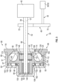
- PDOS 34 includes a motor 40 connected to a motor shaft 42.
- Motor shaft 42 is connected to a door shaft 44 through a gear system 48.
- door shaft 44 extends substantially parallel to motor shaft 42 and is operatively connected to first door 30 and/or second door 32.
- motor shaft 42 and door shaft 44 are also contemplated.
- Motor shaft 42 includes a first end 62, a second end 64 connected to motor 40 and an intermediate portion 66 that is connected to gear system 48. That is, a first gear 70 of gear system 48 is mounted to intermediate portion 66 of motor shaft 42 and a second gear 72 is connected to door shaft 44. Operation of motor 40 causes first gear 70 to rotate second gear 72 which in turn rotates door shaft 44 to shift first door 30 and/or second door 32.
- a one-way speed limiter 80 is connected to first end 62 of motor shaft 42.
- One-way speed limiter 80 allows motor shaft 42 to freely move first door 30 and/or second door 32 to an open configuration as shown in FIG. 2 and mandates a controlled movement of motor shaft 42 to close first door 30.
- One-way speed limiter 80 includes a first housing 82, a second housing 84, and a ball housing 86 that is disposed between and encapsulated by, first housing 82 and second housing 84.
- First housing 82 includes a first wall 89 that defines an outer surface 91 and an inner surface 93. Inner surface 93 defines, in part, a speed limiter receiving zone 95 within which is arranged ball housing 86.
- First wall 89 includes a first annular segment 97 connected to a second annular segment 99 by a first base wall 102.
- Second annular segment 99 extends outwardly from first base wall 102.
- a second base wall 104 is axially spaced from first base wall 102 and is connected to second annular segment 99.
- First annular segment 97 includes a first circumference and second annular segment 99 includes a second circumference that, in the non-limiting example shown, is smaller than the first circumference.
- Second annular segment 99 and second base wall 104 define a stopper housing support 106.
- Second housing 84 includes a flange 110 through which passes motor shaft 42.
- a second wall 112 is connected to flange 110.
- Flange 110 includes an inner surface section 114 and an outer surface section 116.
- Second wall 112 extends substantially perpendicularly from inner surface section 114.
- Second wall 112 includes an outer surface portion 119 and an inner surface portion 121.
- Outer surface portion 119 and inner surface portion 121 are, in a non-limiting example, annular surfaces.
- Outer surface portion 119 abuts inner surface 93 of first wall 89.
- a shim 122 is disposed between second wall 112 and an inner surface (not separately labeled) of first base wall 102.
- Second housing 84 includes a stop feature 124 which, as will be detailed herein, that prevents uncontrolled rotation of motor shaft 42 in a door closing direction. Stop feature 124 is shown in the form of an angular surface 128 that extends between inner surface section 114 and inner surface portion 121.
- ball housing 86 includes a central hub 133 that includes a bearing portion 135 and a clutch portion 137.
- a bearing 140 is arranged in bearing portion 135.
- Bearing 140 supports first end 62 of motor shaft 42.
- Clutch portion 137 supports a one-way clutch 148 that is operatively connected with intermediate portion 66 of motor shaft 42.
- One-way clutch 148 may take the form of a sprag clutch 146 that allows motor shaft 42 to rotate in first direction to open first door 30 and or second door 32 and prevents uncontrolled rotation of motor shaft 42 in a second direction, that is opposite the first direction. That is, motor shaft 42 in the second direction allows first door 30 to close below a designed limiting speed. In second direction, motor shaft 42 and ball housing 86 rotate together due to one-way clutch 148.
- ball housing 86 includes a cup support 150 that extends radially outwardly of central hub 133.
- Cup support 150 includes an outwardly facing circumferential edge 154 that is radially spaced from central hub 133.
- a plurality of cups 158 are formed in cup support 150.
- the plurality of cups 158 extend circumferentially about cup support 150 between central hub 133 and outwardly facing circumferential edge 154.
- each of the plurality of cups 158 includes an opening 162 positioned at outwardly facing circumferential edge 154.
- a ball member 165 is provided in each of the plurality of cups 158.
- Ball member 165 is shown in the form of a spherical ball 169.
- Ball members 165 rest freely in each of the plurality of cups 158. In the event that motor 40 loses power, motor shaft 42 will not spin out of control allowing first door 30 to fall closed.
- a friction clutch 180 is disposed between cup support 150 and an inner surface (not separately labeled) of first base wall 102.
- friction clutch 180 takes the form of a friction plate 182 supporting a plurality of skewed roller bearings 188.
- skewed roller bearings should be understood to describe a roller bearing having an axis of rotation that is skewed relative to a radius extending from an axis of rotation "A" of motor shaft 42.
- friction clutch 180 could take on a variety of forms.
- Loss of electrical power to motor 40 could cause first door 30 and or second door 32 to back drive motor shaft 42.
- Gravity, acting on first door 30 and/or second door 32 could cause a reverse rotation of motor shaft 42 and ball housing 86. due to back drive torque from door shaft 44.
- the reverse rotation of ball housing 86 will generate a force that urges ball members 165 radially outwardly and project through corresponding ones of openings 162.
- one-way speed limiter 80 will prevent first door 30 and/or second door 32 from falling closed in an uncontrolled manner if power to motor 40 is lost. However, one-way speed limiter 80 still allows a controlled closing of first door 30. That is, first door 30 may be slowly lowered, such as by a forklift, and closed without causing friction clutch 180 to fully engage.
Landscapes
- Engineering & Computer Science (AREA)
- General Engineering & Computer Science (AREA)
- Mechanical Engineering (AREA)
- Aviation & Aerospace Engineering (AREA)
- Power-Operated Mechanisms For Wings (AREA)
Claims (15)
- Einweggeschwindigkeitsbegrenzer für ein in einem Flugzeug montiertes motorisiertes Türöffnungssystem, wobei der Einweggeschwindigkeitsbegrenzer Folgendes umfasst:ein erstes Gehäuse (82), das eine erste Wand beinhaltet, die eine Außenfläche und eine Innenfläche beinhaltet, wobei die Innenfläche eine Geschwindigkeitsbegrenzer-Aufnahmezone definiert;ein sich in das erste Gehäuse (82) erstreckendes zweites Gehäuse (84), wobei das zweite Gehäuse (84) einen Flansch beinhaltet, der einen Innenflächenabschnitt und eine sich von dem Flansch nach außen erstreckende zweite Wand aufweist, wobei die zweite Wand einen in die Innenfläche des ersten Gehäuses (82) eingreifenden Außenflächenteil und einen ein Anschlagmerkmal beinhaltenden Innenflächenteil beinhaltet;ein Kugelgehäuse (86), das ein drehbar in der Geschwindigkeitsbegrenzer-Aufnahmezone gelagertes Kugelelement beinhaltet, wobei das Kugelelement selektiv in das Anschlagmerkmal eingreift, um eine axiale Kraft auf dem Kugelgehäuse (86) zu erzeugen;eine zwischen dem Kugelgehäuse (86) und dem ersten Gehäuse (82) angeordnete Reibungskupplung, wobei die Reibungskupplung die Drehung des Kugelgehäuses (86) selektiv verzögert; undeine selektiv drehbar mit dem Kugelgehäuse (86) verbundene Motorwelle (42), wobei die Motorwelle (42) ein am Kugelgehäuse (86) gelagertes erstes Ende und ein zweites Ende beinhaltet, wobei die Motorwelle (42) relativ zu dem Kugelgehäuse (86) in eine erste Richtung drehbar ist und relativ zu dem Kugelgehäuse (86) in eine zweite Richtung selektiv drehbar eingespannt ist, um selektiv in die Reibungskupplung einzugreifen, und dadurch gekennzeichnet, dass das Kugelgehäuse (86) eine ein Lager tragende zentrale Nabe und eine axial von dem Lager beabstandete Einwegkupplung beinhaltet, wobei die Motorwelle (42) mit der Einwegkupplung wirkverbunden ist, wobei das erste Ende der Motorwelle (42) durch das Lager getragen wird.
- Einweggeschwindigkeitsbegrenzer nach Anspruch 1, wobei der Einwegkupplung einen Klemmkörper-Freilauf umfasst.
- Einweggeschwindigkeitsbegrenzer nach Anspruch 1, wobei das Kugelgehäuse (86) eine Vielzahl von Schalen umfasst, die sich um die zentrale Nabe erstreckt und radial außerhalb davon angeordnet ist.
- Einweggeschwindigkeitsbegrenzer nach Anspruch 3, wobei das Kugelelement eine in einer der Vielzahl von Schalen angeordnete Kugel umfasst.
- Einweggeschwindigkeitsbegrenzer nach Anspruch 4, wobei das Kugelelement eine Vielzahl von Kugeln umfasst, die in entsprechenden der Vielzahl von Schalen angeordnet ist.
- Einweggeschwindigkeitsbegrenzer nach Anspruch 2, wobei das Anschlagmerkmal eine abgewinkelte Oberfläche umfasst, die sich zwischen einem Innenflächenabschnitt des Flansches und dem Innenflächenteil der zweiten Wand erstreckt.
- Einweggeschwindigkeitsbegrenzer nach einem der vorhergehenden Ansprüche, wobei die Reibungskupplung eine Reibungsplatte umfasst, die eine Vielzahl von Schräglagern trägt.
- Einweggeschwindigkeitsbegrenzer nach einem der vorhergehenden Ansprüche in Kombination mit:einem mit der Motorwelle (42) verbundenen Motor, wobei der Motor die Motorwelle (42) selektiv in die erste und in die zweite Richtung dreht; undeiner mit der Motorwelle (42) wirkverbundenen Tür.
- Einweggeschwindigkeitsbegrenzer nach Anspruch 8, wobei die Tür auf einer über ein Getriebesystem mit der Motorwelle (42) wirkverbundenen Türwelle montiert ist.
- Flugzeug, umfassend:einen Rumpf (12), der ein Heck beinhaltet;eine von dem Rumpf (12) nach außen ragende Tragfläche (16);ein Triebwerk, das eine entweder von dem Rumpf (12) oder von der Tragfläche (16) getragene Verkleidung beinhaltet;eine entweder an dem Rumpf oder an der Verkleidung bereitgestellte Tür, wobei die Tür ein motorisiertes Türöffnungssystem (PDOS) beinhaltet, das einen Einweggeschwindigkeitsbegrenzer nach einem der vorhergehenden Ansprüche beinhaltet, und dadurch gekennzeichnet, dass das Kugelgehäuse (86) eine ein Lager tragende zentrale Nabe und eine axial von dem Lager beabstandete Einwegkupplung beinhaltet,wobei die Motorwelle (42) mit der Einwegkupplung wirkverbunden ist, wobei das erste Ende der Motorwelle (42) durch das Lager getragen wird.
- Flugzeug nach Anspruch 10, wobei die Einwegkupplung einen Klemmkörper-Freilauf umfasst und/oder wobei das Anschlagmerkmal eine abgewinkelte Oberfläche umfasst, die sich zwischen einem Innenflächenabschnitt des Flansches und dem Innenflächenteil der zweiten Wand erstreckt.
- Flugzeug nach Anspruch 10, wobei das Kugelgehäuse (86) eine Vielzahl von Schalen umfasst, die sich um die zentrale Nabe erstreckt und radial außerhalb davon angeordnet ist.
- Flugzeug nach Anspruch 12, wobei das Kugelelement eine in einer der Vielzahl von Schalen angeordnete Kugel umfasst und wobei das Kugelelement optional eine Vielzahl von Kugeln umfasst, die in entsprechenden der Vielzahl von Schalen angeordnet ist.
- Flugzeug nach einem der Ansprüche 10 bis 13, wobei die Reibungskupplung eine Reibungsplatte umfasst, die eine Vielzahl von Schräglagern trägt.
- Flugzeug nach einem der Ansprüche 10 bis 14, ferner umfassend: einen mit der Motorwelle (42) verbundenen Motor, wobei der Motor die Motorwelle (42) selektiv in die erste und in die zweite Richtung dreht, wobei die Tür mit der Motorwelle (42) wirkverbunden ist und wobei die Tür optional schwenkbar an der Verkleidung montiert ist.
Applications Claiming Priority (1)
| Application Number | Priority Date | Filing Date | Title |
|---|---|---|---|
| IN202211047480 | 2022-08-20 |
Publications (2)
| Publication Number | Publication Date |
|---|---|
| EP4332000A1 EP4332000A1 (de) | 2024-03-06 |
| EP4332000B1 true EP4332000B1 (de) | 2025-06-11 |
Family
ID=87571358
Family Applications (1)
| Application Number | Title | Priority Date | Filing Date |
|---|---|---|---|
| EP23191171.0A Active EP4332000B1 (de) | 2022-08-20 | 2023-08-11 | Einweggeschwindigkeitsbegrenzer für ein motorisiertes türöffnungssystem für ein flugzeug |
Country Status (4)
| Country | Link |
|---|---|
| US (1) | US12214892B2 (de) |
| EP (1) | EP4332000B1 (de) |
| BR (1) | BR102023016401A2 (de) |
| CA (1) | CA3206773A1 (de) |
Family Cites Families (12)
| Publication number | Priority date | Publication date | Assignee | Title |
|---|---|---|---|---|
| US8393568B2 (en) | 2006-07-17 | 2013-03-12 | Eaton Corporation | Enhanced lubrication skewed roller clutch assembly and actuator including same |
| US9650917B2 (en) | 2010-09-24 | 2017-05-16 | Short Brothers Plc | Nacelle with hinged cowl doors enabling access to the engine |
| US9616990B2 (en) * | 2014-07-18 | 2017-04-11 | Hamilton Sundstrand Corporation | Aircraft component rotary device |
| US9703312B2 (en) | 2015-09-29 | 2017-07-11 | Moog Inc. | Non-jamming stop module for high revolution applications |
| US10683691B2 (en) | 2016-04-07 | 2020-06-16 | Magna Closures Inc. | Power swing door actuator with integrated door check mechanism |
| DE102017204914A1 (de) | 2016-04-07 | 2017-10-12 | Magna Closures Inc. | Kraft-Schwenktür-Betätigungsglied mit gelenkigem Verbindungsmechanismus |
| US10655378B2 (en) | 2017-02-07 | 2020-05-19 | Magna Closures Inc. | Power side door actuator with rotating drive nut |
| FR3067004B1 (fr) * | 2017-05-30 | 2021-04-16 | Airbus Operations Sas | Systeme de propulsion d'un aeronef comportant une nacelle avec un systeme d'ouverture ameliore |
| US10816070B2 (en) | 2018-09-26 | 2020-10-27 | Woodward, Inc. | Geared rotary power distribution unit with mechanical differential gearing for multiple actuator systems |
| US11421463B2 (en) | 2019-09-09 | 2022-08-23 | Hamilton Sundstrand Corporation | One-way clutch for use in a no-back clutch design |
| EP3798134B1 (de) * | 2019-09-30 | 2024-05-29 | Rohr, Inc. | Verbindung(en) zwischen innerer und äusserer triebwerksverkleidung |
| US11623739B2 (en) * | 2020-10-27 | 2023-04-11 | Eaton Intelligent Power Limited | Electromechanical actuator with no-back system |
-
2022
- 2022-10-18 US US17/967,985 patent/US12214892B2/en active Active
-
2023
- 2023-07-17 CA CA3206773A patent/CA3206773A1/en active Pending
- 2023-08-11 EP EP23191171.0A patent/EP4332000B1/de active Active
- 2023-08-15 BR BR102023016401-3A patent/BR102023016401A2/pt unknown
Also Published As
| Publication number | Publication date |
|---|---|
| CA3206773A1 (en) | 2024-02-20 |
| US20240060344A1 (en) | 2024-02-22 |
| BR102023016401A2 (pt) | 2024-03-12 |
| US12214892B2 (en) | 2025-02-04 |
| EP4332000A1 (de) | 2024-03-06 |
Similar Documents
| Publication | Publication Date | Title |
|---|---|---|
| US11619344B2 (en) | Elevation device and robot | |
| EP0983937B2 (de) | Bremseinrichtung ohne Rückwärtsgang für einen Stellantrieb eines Flugzeuges | |
| US5865235A (en) | Counterbalance mechanism for vertical opening door | |
| CA2610368A1 (en) | De-rotation system for counter-rotating, coaxial rotor hub shaft fairing | |
| AU2012339688A1 (en) | Centrifugal de-clutch | |
| EP3715660B1 (de) | Selbsteinstellende automatische lastbremse | |
| US9863515B2 (en) | Self-locking no-back actuator | |
| EP4332000B1 (de) | Einweggeschwindigkeitsbegrenzer für ein motorisiertes türöffnungssystem für ein flugzeug | |
| EP2725253A2 (de) | Zentrifugale Rückwärtsdrallbremse | |
| US20180118515A1 (en) | Remote triggering device, overspeed governor assembly and elevator | |
| US20210387831A1 (en) | Speed limiter for a lifting gear having brake actuated by centrifugal force | |
| US4817771A (en) | Spring clutch with engageable first and second helical clutch springs | |
| US20140135132A1 (en) | Non-chattering ball detent torque limiter | |
| US3897651A (en) | Revolving door speed control and hanger mechanism | |
| SE510300C2 (sv) | Momentöverförande anordning | |
| US7140475B1 (en) | Brake | |
| FI114503B (fi) | Momenttiohjatusti toimiva jarru | |
| JP3853090B2 (ja) | シャッターの軸受 | |
| EP4265931B1 (de) | Asymmetrischer mechanischer drehmomentbegrenzer | |
| EP1754914A1 (de) | Scheibe für einen Wechselstromgenerator | |
| US9074727B2 (en) | Safety guard for a rotatable member | |
| EP3882133A1 (de) | Schaufelwinkelbetätigungsmechanismus | |
| DE102008004712A1 (de) | Bremsvorrichtung für eine Windturbine | |
| JPS6354144B2 (de) | ||
| EP2893232B1 (de) | Elektrischer stellantrieb |
Legal Events
| Date | Code | Title | Description |
|---|---|---|---|
| PUAI | Public reference made under article 153(3) epc to a published international application that has entered the european phase |
Free format text: ORIGINAL CODE: 0009012 |
|
| STAA | Information on the status of an ep patent application or granted ep patent |
Free format text: STATUS: THE APPLICATION HAS BEEN PUBLISHED |
|
| AK | Designated contracting states |
Kind code of ref document: A1 Designated state(s): AL AT BE BG CH CY CZ DE DK EE ES FI FR GB GR HR HU IE IS IT LI LT LU LV MC ME MK MT NL NO PL PT RO RS SE SI SK SM TR |
|
| STAA | Information on the status of an ep patent application or granted ep patent |
Free format text: STATUS: REQUEST FOR EXAMINATION WAS MADE |
|
| 17P | Request for examination filed |
Effective date: 20240902 |
|
| RBV | Designated contracting states (corrected) |
Designated state(s): AL AT BE BG CH CY CZ DE DK EE ES FI FR GB GR HR HU IE IS IT LI LT LU LV MC ME MK MT NL NO PL PT RO RS SE SI SK SM TR |
|
| GRAP | Despatch of communication of intention to grant a patent |
Free format text: ORIGINAL CODE: EPIDOSNIGR1 |
|
| STAA | Information on the status of an ep patent application or granted ep patent |
Free format text: STATUS: GRANT OF PATENT IS INTENDED |
|
| INTG | Intention to grant announced |
Effective date: 20250109 |
|
| GRAS | Grant fee paid |
Free format text: ORIGINAL CODE: EPIDOSNIGR3 |
|
| GRAA | (expected) grant |
Free format text: ORIGINAL CODE: 0009210 |
|
| STAA | Information on the status of an ep patent application or granted ep patent |
Free format text: STATUS: THE PATENT HAS BEEN GRANTED |
|
| AK | Designated contracting states |
Kind code of ref document: B1 Designated state(s): AL AT BE BG CH CY CZ DE DK EE ES FI FR GB GR HR HU IE IS IT LI LT LU LV MC ME MK MT NL NO PL PT RO RS SE SI SK SM TR |
|
| REG | Reference to a national code |
Ref country code: GB Ref legal event code: FG4D |
|
| REG | Reference to a national code |
Ref country code: CH Ref legal event code: EP |
|
| REG | Reference to a national code |
Ref country code: IE Ref legal event code: FG4D |
|
| REG | Reference to a national code |
Ref country code: DE Ref legal event code: R096 Ref document number: 602023003922 Country of ref document: DE |
|
| PG25 | Lapsed in a contracting state [announced via postgrant information from national office to epo] |
Ref country code: ES Free format text: LAPSE BECAUSE OF FAILURE TO SUBMIT A TRANSLATION OF THE DESCRIPTION OR TO PAY THE FEE WITHIN THE PRESCRIBED TIME-LIMIT Effective date: 20250611 Ref country code: FI Free format text: LAPSE BECAUSE OF FAILURE TO SUBMIT A TRANSLATION OF THE DESCRIPTION OR TO PAY THE FEE WITHIN THE PRESCRIBED TIME-LIMIT Effective date: 20250611 |
|
| PGFP | Annual fee paid to national office [announced via postgrant information from national office to epo] |
Ref country code: DE Payment date: 20250812 Year of fee payment: 3 |
|
| REG | Reference to a national code |
Ref country code: LT Ref legal event code: MG9D |
|
| PG25 | Lapsed in a contracting state [announced via postgrant information from national office to epo] |
Ref country code: NO Free format text: LAPSE BECAUSE OF FAILURE TO SUBMIT A TRANSLATION OF THE DESCRIPTION OR TO PAY THE FEE WITHIN THE PRESCRIBED TIME-LIMIT Effective date: 20250911 Ref country code: GR Free format text: LAPSE BECAUSE OF FAILURE TO SUBMIT A TRANSLATION OF THE DESCRIPTION OR TO PAY THE FEE WITHIN THE PRESCRIBED TIME-LIMIT Effective date: 20250912 |
|
| PGFP | Annual fee paid to national office [announced via postgrant information from national office to epo] |
Ref country code: IT Payment date: 20250901 Year of fee payment: 3 |
|
| REG | Reference to a national code |
Ref country code: NL Ref legal event code: MP Effective date: 20250611 |
|
| PG25 | Lapsed in a contracting state [announced via postgrant information from national office to epo] |
Ref country code: BG Free format text: LAPSE BECAUSE OF FAILURE TO SUBMIT A TRANSLATION OF THE DESCRIPTION OR TO PAY THE FEE WITHIN THE PRESCRIBED TIME-LIMIT Effective date: 20250611 |
|
| PG25 | Lapsed in a contracting state [announced via postgrant information from national office to epo] |
Ref country code: HR Free format text: LAPSE BECAUSE OF FAILURE TO SUBMIT A TRANSLATION OF THE DESCRIPTION OR TO PAY THE FEE WITHIN THE PRESCRIBED TIME-LIMIT Effective date: 20250611 |
|
| PGFP | Annual fee paid to national office [announced via postgrant information from national office to epo] |
Ref country code: FR Payment date: 20250829 Year of fee payment: 3 Ref country code: AT Payment date: 20251020 Year of fee payment: 3 |
|
| PG25 | Lapsed in a contracting state [announced via postgrant information from national office to epo] |
Ref country code: RS Free format text: LAPSE BECAUSE OF FAILURE TO SUBMIT A TRANSLATION OF THE DESCRIPTION OR TO PAY THE FEE WITHIN THE PRESCRIBED TIME-LIMIT Effective date: 20250911 |
|
| PG25 | Lapsed in a contracting state [announced via postgrant information from national office to epo] |
Ref country code: LV Free format text: LAPSE BECAUSE OF FAILURE TO SUBMIT A TRANSLATION OF THE DESCRIPTION OR TO PAY THE FEE WITHIN THE PRESCRIBED TIME-LIMIT Effective date: 20250611 |
|
| PG25 | Lapsed in a contracting state [announced via postgrant information from national office to epo] |
Ref country code: NL Free format text: LAPSE BECAUSE OF FAILURE TO SUBMIT A TRANSLATION OF THE DESCRIPTION OR TO PAY THE FEE WITHIN THE PRESCRIBED TIME-LIMIT Effective date: 20250611 |
|
| PG25 | Lapsed in a contracting state [announced via postgrant information from national office to epo] |
Ref country code: PT Free format text: LAPSE BECAUSE OF FAILURE TO SUBMIT A TRANSLATION OF THE DESCRIPTION OR TO PAY THE FEE WITHIN THE PRESCRIBED TIME-LIMIT Effective date: 20251013 |
|
| REG | Reference to a national code |
Ref country code: AT Ref legal event code: MK05 Ref document number: 1802172 Country of ref document: AT Kind code of ref document: T Effective date: 20250611 |
|
| PG25 | Lapsed in a contracting state [announced via postgrant information from national office to epo] |
Ref country code: IS Free format text: LAPSE BECAUSE OF FAILURE TO SUBMIT A TRANSLATION OF THE DESCRIPTION OR TO PAY THE FEE WITHIN THE PRESCRIBED TIME-LIMIT Effective date: 20251011 |
|
| PG25 | Lapsed in a contracting state [announced via postgrant information from national office to epo] |
Ref country code: AT Free format text: LAPSE BECAUSE OF FAILURE TO SUBMIT A TRANSLATION OF THE DESCRIPTION OR TO PAY THE FEE WITHIN THE PRESCRIBED TIME-LIMIT Effective date: 20250611 Ref country code: SM Free format text: LAPSE BECAUSE OF FAILURE TO SUBMIT A TRANSLATION OF THE DESCRIPTION OR TO PAY THE FEE WITHIN THE PRESCRIBED TIME-LIMIT Effective date: 20250611 |
|
| PG25 | Lapsed in a contracting state [announced via postgrant information from national office to epo] |
Ref country code: CZ Free format text: LAPSE BECAUSE OF FAILURE TO SUBMIT A TRANSLATION OF THE DESCRIPTION OR TO PAY THE FEE WITHIN THE PRESCRIBED TIME-LIMIT Effective date: 20250611 |
|
| PG25 | Lapsed in a contracting state [announced via postgrant information from national office to epo] |
Ref country code: PL Free format text: LAPSE BECAUSE OF FAILURE TO SUBMIT A TRANSLATION OF THE DESCRIPTION OR TO PAY THE FEE WITHIN THE PRESCRIBED TIME-LIMIT Effective date: 20250611 |
|
| PG25 | Lapsed in a contracting state [announced via postgrant information from national office to epo] |
Ref country code: EE Free format text: LAPSE BECAUSE OF FAILURE TO SUBMIT A TRANSLATION OF THE DESCRIPTION OR TO PAY THE FEE WITHIN THE PRESCRIBED TIME-LIMIT Effective date: 20250611 |
|
| PG25 | Lapsed in a contracting state [announced via postgrant information from national office to epo] |
Ref country code: SK Free format text: LAPSE BECAUSE OF FAILURE TO SUBMIT A TRANSLATION OF THE DESCRIPTION OR TO PAY THE FEE WITHIN THE PRESCRIBED TIME-LIMIT Effective date: 20250611 |