EP4331978A1 - Drehflügelflugzeug mit einem blattspitzenbeleuchtungssystem - Google Patents
Drehflügelflugzeug mit einem blattspitzenbeleuchtungssystem Download PDFInfo
- Publication number
- EP4331978A1 EP4331978A1 EP22400008.3A EP22400008A EP4331978A1 EP 4331978 A1 EP4331978 A1 EP 4331978A1 EP 22400008 A EP22400008 A EP 22400008A EP 4331978 A1 EP4331978 A1 EP 4331978A1
- Authority
- EP
- European Patent Office
- Prior art keywords
- light
- rotorcraft
- rotor
- light beam
- night
- Prior art date
- Legal status (The legal status is an assumption and is not a legal conclusion. Google has not performed a legal analysis and makes no representation as to the accuracy of the status listed.)
- Granted
Links
Images

Classifications
-
- B—PERFORMING OPERATIONS; TRANSPORTING
- B64—AIRCRAFT; AVIATION; COSMONAUTICS
- B64C—AEROPLANES; HELICOPTERS
- B64C27/00—Rotorcraft; Rotors peculiar thereto
- B64C27/008—Rotors tracking or balancing devices
Definitions
- the invention is related to a rotorcraft with a blade tip illumination system.
- flight conditions may also be challenging for pilots. For instance, comparatively slow helicopter side drift due to repetitive side wind gusts may easily go unnoticed by the pilot and result in a stepwise drifting of the helicopter towards the wind turbine generator structure and/or its wind turbine blades. Moreover, in flight conditions with comparatively low visibility, e. g. due to night time, visibility to certain position reference points at the wind turbine generator may also be rather limited.
- the pilot may be placed in a position to prevent a potentially disastrous rotor strike of the helicopter's rotor blades against the wind turbine generator structure and/or its wind turbine blades by providing the pilot with precise and reliable information with respect to distances between the helicopter and the wind turbine generator structure and/or its wind turbine blades.
- the document EP 3 072 813 B1 describes a helicopter comprising a helicopter light system with layer material and light sources.
- the layer material comprises at least one of a fluorescent material and a phosphorescent material.
- the light sources comprise any appropriate lighting device, such as a light bulb, LED, or OLED in any appropriate number, which is capable of generating light in appropriate color and of sufficient lighting power to be directed onto the layer material for sufficient light emission and/or reflection by the layer material.
- the helicopter comprises a helicopter body, which includes a main frame and a tail boom.
- the helicopter comprises multiple rotor blades, each rotor blade having rotor blade tips at both of its ends, wherein layer material of the helicopter light system is arranged at only one rotor tip or at both rotor tips of a given rotor blade.
- the layer material is arranged on a side of the rotor blade tip of the given rotor blade that faces the helicopter body, which side is a bottom side of the given rotor blade.
- the layer material emits and/or reflects visible light
- the rotor blades are clearly visible in a night time mission of the helicopter not only to the pilot, but also to other people which are not necessarily onboard the helicopter. These other people would, thus, be able to distinguish and trace the helicopter in its night time mission, which may for instance represent a potential danger in military helicopter operation.
- the pilot or other crew members wear night vision devices, they may be blinded by the visible light.
- an object of the present invention to provide a new rotorcraft with a blade tip illumination system that is suitable to overcome the above-described drawbacks and problems of the state-of-the-art.
- a rotorcraft comprising the features of claim 1. More specifically, according to the present invention a rotorcraft is provided that comprises at least one main rotor, at least one light returning unit, and a blade tip illumination device.
- the at least one main rotor comprises a rotor head and a plurality of rotor blades extending from the rotor head toward associated rotor blade tips.
- the associated rotor blade tips form a virtual blade tip circle upon rotation around the rotor head.
- the at least one light returning unit is provided on at least one of the associated rotor blade tips.
- the blade tip illumination device comprises at least one light source configured to emit a light beam toward at least a portion of the virtual blade tip circle for illuminating the at least one light returning unit.
- the at least one light returning unit is adapted to return light in response to being illuminated with the emitted light beam.
- the returned light has a wavelength suitable for detection by a night-vision device and forms during rotation of the associated rotor blade tips around the rotor head on the virtual blade tip circle at least a luminous ring segment visible via the night-vision device.
- the inventive blade tip illumination system with the blade tip illumination device and the at least one light returning unit enables particularly in night time missions a clear indication of the rotor blade tips to a pilot of the rotorcraft, thereby increasing safety of flight and maneuver potential of the rotorcraft.
- the blade tip illumination system has a simple low-cost configuration and avoids a requirement for expensive additional components.
- such a low-cost configuration may be obtained by painting conventional standard rotor blades on their rotor blade tips with reflective paintings or coatings (e. g. glossy effect).
- low-cost stickers may be attached to the rotor blade tips.
- application of the reflective paintings or coatings, or stickers is not limited to the rotor blade tips, but could also be made on the entire rotor blades or one or more selected sections thereof.
- one or more light sources e. g. white and/or infrared
- their respective light beams are directed towards the rotor blades and, more particularly, to the rotor blade tips.
- the reflection of the light beams is preferably detectable at least with night-vision devices and may, thus, be made visible to rotorcraft personnel or crew.
- the reflective paintings or coatings, or stickers reflect the light beams only in sections of a respective virtual rotor disk, i. e. in sections of the virtual blade tip circle, formed by rotation of the rotor blades where the light beam illuminates, i. e. hits the reflective paintings or coatings, or stickers, which may then be made visible in night time missions with night-vision devices.
- a respective virtual rotor disk i. e. in sections of the virtual blade tip circle, formed by rotation of the rotor blades where the light beam illuminates, i. e. hits the reflective paintings or coatings, or stickers, which may then be made visible in night time missions with night-vision devices.
- the reflective paintings or coatings, or stickers reflect the light beams only in sections of a respective virtual rotor disk, i. e. in sections of the virtual blade tip circle, formed by rotation of the rotor blades where the light beam illuminates, i. e. hits the reflective paintings or coatings, or stickers, which may then be made visible in night time
- the light beam in order to ensure visibility of the rotor blade tips the light beam must be designed in a way to cover a respectively desired section of the rotor blades in any flight state as only illuminated areas are visible. Furthermore, a respectively applied light source power needs to be adjusted in order not to blind rotorcraft personnel or crew wearing night-vision devices. However, dependent on mission focus, visible (e. g. white light) or non-visible light (e. g. infrared light) may preferably be used.
- visible e. g. white light
- non-visible light e. g. infrared light
- a light source such as e. g. LED, Halogen, Laser, Xenon, etc. is used which emits some light in infrared spectrum for reflection by the reflective paintings or coatings, or stickers, such that respectively reflected light may be detected by the night-vision device (any type of night-vision device and no matter which class, as they are detecting different wavelengths better or worse; class a, b, or c).
- the night-vision device any type of night-vision device and no matter which class, as they are detecting different wavelengths better or worse; class a, b, or c.
- the light source may also emit some light in the whole spectrum from ultraviolet to infrared.
- a suitable lighting power for infrared light of the light source is approximately 0,1 W/sr.
- For white light (measured in cd) approximately 1000 cd appear to be acceptable.
- a suitable level of lighting power of the light source is required so that the light beam will be reflected by the reflective paintings or coatings, or stickers, but neither too much so that the pilot is blinded, nor too few such that the pilot may not recognize anything.
- the glossiness of the reflective paintings or coatings, or stickers preferably at least 90 Gloss units are implemented.
- the position of the light sources is preferably on the left and right side of the rotorcraft, in the case of a helicopter preferably on the upper deck behind the cockpit, but it is not only limited to this position. In fact, the position must only be suitable to emit the light beam towards the rotor blade tips and to get some reflected light back from the reflective paintings or coatings, or stickers to be visualized with the night-vision device.
- An illustrative reflective painting on a given rotor blade tip preferably comprises a base coat that enables application of a paint, a phosphorescent paint applied on the base coat to make the rotor blade tip visible without night-vision device, and a glossy clear coat to make the rotor blade tip visible with the night-vision device. In other words, only the glossy clear coat is required for use with the night-vision device.
- the wavelength suitable for detection by a night-vision device is comprised in a wavelength spectrum ranging from 450 nm to 930 nm, preferably from 650 nm to 850 nm.
- the emitted light beam comprises infrared light.
- the emitted light beam may be an infrared light beam with a radiant intensity of approximately 0.1 W/sr.
- the emitted light beam may alternatively be a white light beam with a luminous intensity of approximately 1000 cd.
- the at least one light source may be one of a LED, Halogen, Laser or Xenon light.
- the at least one light returning unit comprises a light returning sticker attached on the at least one of the associated rotor blade tips, and/or a light returning coating applied to the at least one of the associated rotor blade tips.
- the light returning coating may comprise at least a base coating and a glossy clear coating.
- the glossy clear coating may comprise a glossiness of more than 90 Gloss units.
- the returned light may have a wavelength suitable for detection without a night-vision device, if the emitted light beam is a white light beam with a luminous intensity of more than 1000 cd and, preferably, a maximum of 2000 cd.
- the rotorcraft may further comprise a command unit configured to command the at least one light source to emit one of the white light beam, in an associated night-vision free mode, or an infrared light beam with a radiant intensity of approximately 0.1 W/sr, in an associated night-vision mode.
- the at least one light returning unit may comprise a light returning sticker attached on the at least one of the associated rotor blade tips, and/or a light returning coating applied to the at least one of the associated rotor blade tips.
- the light returning coating may comprise at least a base coating, a phosphorescent layer, and a glossy clear coating.
- the phosphorescent layer is adapted to return light in response to being illuminated with a white light beam
- the glossy clear coating is adapted to return light in response to being illuminated with an infrared light beam.
- the fuselage forms a starboard side wall and a portside wall
- the at least one light source comprises a first light source provided on the portside wall and a second light source provided on the starboard side wall.
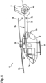
- FIG. 1 shows a rotorcraft 1 that is exemplarily illustrated as a helicopter.
- helicopter 1 the rotorcraft 1
- the present invention is, however, not limited to helicopters and may likewise be applied to any other rotorcraft.
- the helicopter 1 comprises at least one main rotor 1a, preferably a multi-blade main rotor, for providing lift and forward or backward thrust during operation.
- the at least one main rotor 1a comprises a plurality of rotor blades which are connected at an associated rotor head 1d to a rotor shaft 1e, which rotates in operation of the helicopter 1 about an associated rotor axis.
- Two rotor blades of the plurality of rotor blades are visible in Figure 1 and separately labelled with the reference signs 1b, 1c.
- the helicopter 1 comprises a fuselage 2 that preferably forms an aircraft interior region 2a.
- a lefthand side of the fuselage 2 is shown and, thus, a portside wall (2d in Figure 2 ) of the fuselage 2 of the helicopter 1, to which a landing gear 1f of the skid-type is attached, by way of example.
- the aircraft interior region 2a may accommodate a cockpit and may further accommodate a cabin for passengers and/or cargo.
- a tail boom 3 with a horizontal stabilizer 3a is connected at a rear fuselage 2b to the fuselage 2 of the helicopter 1.
- the tail boom 3 is illustratively implemented as a slim beam element that comprises at least a tubular tail boom cone 3b.
- the helicopter 1 illustratively further comprises at least one preferentially shrouded counter-torque device 4 configured to provide counter-torque during operation, i. e. to counter the torque created by rotation of the at least one main rotor 1a for purposes of balancing the helicopter 1 in terms of yaw.
- the at least one counter-torque device 4 is illustratively provided at an aft section of the tail boom 3 and preferably comprises a tail rotor 4a.
- the aft section of the tail boom 3 preferably further comprises a fin 5.
- FIG. 2 shows the helicopter 1 of Figure 1 seen from above.
- the helicopter 1 comprises the fuselage 2 that illustratively forms a starboard side wall 2c and a portside wall 2d, and that is connected at the rear fuselage 2b to the tail boom 3 which comprises the horizontal stabilizer 3a, the counter-torque device 4 and the fin 5.
- the helicopter 1 further comprises the at least one main rotor 1a with the plurality of rotor blades which are connected at the rotor head 1d to the rotor shaft 1e.
- the plurality of rotor blades comprises the rotor blades 1b, 1c of Figure 1 , as well as two additional rotor blades 1g, 1h.
- the plurality of rotor blades 1b, 1c, 1g, 1h extend from the rotor head 1d toward associated rotor blade tips 6b, 6c, 6g, 6h.
- the rotor blade tips 6b, 6c, 6g, 6h form a virtual blade tip circle (6i in Figure 4 ) upon rotation around the rotor head 1d.
- a blade tip illumination system with a blade tip illumination device 7 and at least one light returning unit (9b, 9h in Figure 3 ) is provided.
- the at least one light returning unit is provided on at least one of the rotor blade tips 6b, 6c, 6g, 6h, as described in more detail below at Figure 3 and Figure 4 .
- the blade tip illumination device 7 comprises at least one light source configured to emit a light beam toward at least a portion of the virtual blade tip circle (6i in Figure 4 ) for illuminating the at least one light returning unit.
- the at least one light source may be one of a LED, Halogen, Laser or Xenon light.
- the blade tip illumination device 7 comprises two light sources 7a, 7b, each one being configured to emit an associated light beam 8a, 8b toward at least a portion of the virtual blade tip circle for illuminating the at least one light returning unit (9b, 9h in Figure 3 ).
- Each light returning unit (9b, 9h in Figure 3 ) is adapted to return light in response to being illuminated with one of the emitted light beams 8a, 8b, as described in more detail below at Figure 3 .
- Each light returning unit may comprise a light returning sticker attached on an associated one of the rotor blade tips 6b, 6c, 6g, 6h, and/or a light returning coating (13a, 13b, 13c in Figure 5 ) applied to the associated one of the rotor blade tips 6b, 6c, 6g, 6h.
- the two light sources 7a, 7b are arranged close to the rear fuselage 2 of the helicopter 1.
- the two light sources 7a, 7b and the light returning units provided on the rotor blade tips 6b, 6c, 6g, 6h are preferably configured such that returned light from the light returning units forms during rotation of the rotor blade tips 6b, 6c, 6g, 6h around the rotor head 1d on the virtual blade tip circle (6i in Figure 4 ) a luminous ring.
- the returned light may have a wavelength suitable for detection without a night-vision device.
- the emitted light beams 8a, 8b are preferably white light beams with a luminous intensity of more than 1000 cd and, preferentially, a maximum of 2000 cd.
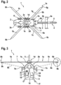
- FIG 3 shows the helicopter 1 of Figure 2 seen from the front.
- the helicopter 1 comprises the fuselage 2 that forms the aircraft interior region 2a, the starboard side wall 2c, and the portside wall 2d.
- the helicopter 1 further comprises the at least one main rotor 1a with the plurality of rotor blades 1b, 1h which are connected at the rotor head 1d to the rotor shaft 1e and which extend from the rotor head 1d toward the rotor blade tips 6b, 6h.
- the rotor blade tips 6b, 6h form a virtual blade tip circle (6i in Figure 4 ) upon rotation around the rotor head 1d.
- the helicopter 1 comprises the blade tip illumination system with the blade tip illumination device 7 having the two light sources 7a, 7b, which emit the light beams 8a, 8b, as well as the at least one light returning unit.
- each one of the rotor blade tips is provided with an associated light returning unit.
- the rotor blade tip 6b is provided with a light returning unit 9b
- the rotor blade tip 6h is provided with a light returning unit 9h.
- the light returning units 9b, 9h are arranged on an underside of the rotor blade tips 6b, 6h such that they are visible from the aircraft interior region 2a, e. g. at least from a pilot 10 in the cockpit of the helicopter 1.
- the pilot 10 is wearing a night-vision device 11.
- the light returning units 9b, 9h are illuminated with the light beams 8a, 8b emitted from the light sources 7a, 7b which are now illustratively arranged in a front portion of the helicopter 1 close to the cockpit.
- the light returning unit 9b is illuminated with the light beam 8a
- the light returning unit 9h is illuminated with the light beam 8b.
- Each one of the light returning units 9b, 9h is adapted to return light in response to being illuminated with one of the emitted light beams 8a, 8b.
- the light returning unit 9b returns light in response to being illuminated with the emitted light beam 8a
- the light returning unit 9h returns light in response to being illuminated with the emitted light beam 8b.
- the emitted light beams 8a, 8b preferably comprise infrared light. More specifically, the emitted light beams 8a, 8b are preferably infrared light beams with a radiant intensity of approximately 0.1 W/sr. Alternatively, the emitted light beams 8a, 8b may be white light beams with a luminous intensity of approximately 1000 cd.
- the returned light forms during rotation of the rotor blade tips 6b, 6h around the rotor head 1d on the virtual blade tip circle (6i in Figure 4 ) at least a luminous ring segment (12 in Figure 4 ) visible via the night-vision device 11. Therefore, the returned light from the light returning units 9b, 9h has a wavelength suitable for detection by the night-vision device 11.
- the wavelength suitable for detection by the night-vision device 11 is preferably comprised in a wavelength spectrum ranging from 450 nm to 930 nm, preferably from 650 nm to 850 nm.
- FIG 4 shows the helicopter 1 of Figure 3 seen from above, similar to the representation in Figure 2 .
- the helicopter 1 comprises the fuselage 2 that forms the aircraft interior region 2a, the starboard side wall 2c, and the portside wall 2d.
- the helicopter 1 further comprises the at least one main rotor 1a with the plurality of rotor blades 1b, 1c, 1g, 1h which are connected at the rotor head 1d to the rotor shaft 1e and which extend from the rotor head 1d toward the rotor blade tips 6b, 6c, 6g, 6h.
- the helicopter 1 comprises the blade tip illumination system with the blade tip illumination device 7 having the two light sources 7a, 7b, which emit the light beams 8a, 8b, as well as the light returning units provided on the rotor blade tips 6b, 6c, 6g, 6h.
- the rotor blades 1b, 1c, 1g, 1h and, thus, the rotor blade tips 6b, 6c, 6g, 6h rotate around the rotor head 1d.
- the rotor blade tips 6b, 6c, 6g, 6h form a virtual blade tip circle 6i.
- the blade tip circle 6i is referred to as being "virtual”, as actually no circle is formed.
- the rotor blade tips 6b, 6c, 6g, 6h are merely travelling along a circular path around the rotor head 1d.
- the light returning units provided on the rotor blade tips 6b, 6c, 6g, 6h are illuminated with the light beams 8a, 8b emitted from the light sources 7a, 7b which are arranged in the front portion of the helicopter 1 close to the cockpit.
- Each one of the light beams 8a, 8b is preferably formed to illuminate a predetermined segment of the virtual blade tip circle 6i.
- the light returning units provided on the rotor blade tips 6b, 6c, 6g, 6h are illuminated with the light beams 8a, 8b emitted from the light sources 7a, 7b only in the predetermined segments of the virtual blade tip circle 6i.
- each one of the light returning units returns light in response to being illuminated with one of the emitted light beams 8a, 8b.
- each one of the light returning units returns only light as long as it is illuminated with one of the emitted light beams 8a, 8b. Accordingly, the returned light forms on the virtual blade tip circle 6i only a luminous ring segment 12, illustratively in front of the cockpit.
- Figure 5 shows the rotor blade tip 6b of the rotor blade 1b of Figure 2 to Figure 4 , which is provided with the light returning unit 9b as described above at Figure 3 .
- the light returning unit 9b may comprise a light returning sticker attached on the rotor blade tip 6b, and/or a light returning coating applied to the rotor blade tip 6b.
- the light returning unit 9b is formed as a light returning coating.
- the light returning coating comprises at least a base coating 13a and a glossy clear coating 13c.
- the glossy clear coating 13c is at least adapted to return light in response to being illuminated with an infrared light beam and may be formed with a glossiness of more than 90 Gloss units.
- the light returning coating may further comprise a phosphorescent layer 13b.
- the phosphorescent layer 13b may be adapted to return light at least in response to being illuminated with a white light beam.
- the light sources 7a, 7b are arranged in a front portion of the helicopter 1 and the returned light from the light returning units 9a, 9b has a wavelength suitable for detection by the night-vision device 11, e. g. in an associated night-vision mode
- the light sources 7a, 7b are arranged close to the rear fuselage 2b of the helicopter 1 and the returned light from the light returning units 9a, 9b has a wavelength suitable for detection without a night-vision device, e. g. in an associated night-vision free mode.
- the helicopter 1 may also be configured to enable both the night-vision mode and the night-vision free mode.
- the helicopter 1 may be provided with a command unit configured to command the light sources 7a, 7b to emit either white light beams in the night-vision free mode, or infrared light beams with radiant intensities of approximately 0.1 W/sr in the night-vision mode.
- a respective command unit is exemplified in Figure 3 and labelled therein with the reference sign 14.
- each light source may be configured to emit either a white light beam, or an infrared light beam.
- each light source may be configured to emit either a white light beam, or an infrared light beam.
- four light sources may be provided, for instance two light sources according to the configuration of Figure 2 , which may be configured to emit only white light beams, and two light sources according to the configuration of Figure 3 , which may be configured to emit only infrared light beams.
- Figure 2 to Figure 5 make only reference to light returning units provided on rotor blade tips.
- one or more rotor blades may also be provided with more than one light returning unit.
- a given rotor blade may be provided with a plurality of light returning units which are spaced apart from each other on the given rotor blade, and so on.
Landscapes
- Engineering & Computer Science (AREA)
- Mechanical Engineering (AREA)
- Aviation & Aerospace Engineering (AREA)
- Toys (AREA)
- Wind Motors (AREA)
Priority Applications (1)
| Application Number | Priority Date | Filing Date | Title |
|---|---|---|---|
| EP22400008.3A EP4331978B1 (de) | 2022-08-29 | 2022-08-29 | Drehflügelflugzeug mit einem blattspitzenbeleuchtungssystem |
Applications Claiming Priority (1)
| Application Number | Priority Date | Filing Date | Title |
|---|---|---|---|
| EP22400008.3A EP4331978B1 (de) | 2022-08-29 | 2022-08-29 | Drehflügelflugzeug mit einem blattspitzenbeleuchtungssystem |
Publications (3)
| Publication Number | Publication Date |
|---|---|
| EP4331978A1 true EP4331978A1 (de) | 2024-03-06 |
| EP4331978C0 EP4331978C0 (de) | 2025-07-23 |
| EP4331978B1 EP4331978B1 (de) | 2025-07-23 |
Family
ID=84330285
Family Applications (1)
| Application Number | Title | Priority Date | Filing Date |
|---|---|---|---|
| EP22400008.3A Active EP4331978B1 (de) | 2022-08-29 | 2022-08-29 | Drehflügelflugzeug mit einem blattspitzenbeleuchtungssystem |
Country Status (1)
| Country | Link |
|---|---|
| EP (1) | EP4331978B1 (de) |
Citations (4)
| Publication number | Priority date | Publication date | Assignee | Title |
|---|---|---|---|---|
| DE102014223727A1 (de) * | 2014-11-20 | 2016-05-25 | Airbus Defence and Space GmbH | Passive Rotorblattspitzenbeleuchtung |
| CN108802732A (zh) * | 2018-06-14 | 2018-11-13 | 中航金林科技(北京)有限公司 | 直升机翼尖显示装置 |
| CN109018394A (zh) * | 2018-07-10 | 2018-12-18 | 中航金林科技(北京)有限公司 | 直升机翼尖照明方法 |
| EP3072813B1 (de) | 2015-03-27 | 2020-01-15 | Goodrich Lighting Systems GmbH | Hubschrauberbeleuchtungssystem mit einem schichtmaterial zur anordnung auf einer rotorblattspitze des hubschraubers sowie hubschrauber damit |
-
2022
- 2022-08-29 EP EP22400008.3A patent/EP4331978B1/de active Active
Patent Citations (4)
| Publication number | Priority date | Publication date | Assignee | Title |
|---|---|---|---|---|
| DE102014223727A1 (de) * | 2014-11-20 | 2016-05-25 | Airbus Defence and Space GmbH | Passive Rotorblattspitzenbeleuchtung |
| EP3072813B1 (de) | 2015-03-27 | 2020-01-15 | Goodrich Lighting Systems GmbH | Hubschrauberbeleuchtungssystem mit einem schichtmaterial zur anordnung auf einer rotorblattspitze des hubschraubers sowie hubschrauber damit |
| CN108802732A (zh) * | 2018-06-14 | 2018-11-13 | 中航金林科技(北京)有限公司 | 直升机翼尖显示装置 |
| CN109018394A (zh) * | 2018-07-10 | 2018-12-18 | 中航金林科技(北京)有限公司 | 直升机翼尖照明方法 |
Non-Patent Citations (3)
| Title |
|---|
| ANONYMOUS: "Whats the limit on white light for saving night vision?", CANDLE POWER FORUMS, 1 September 2006 (2006-09-01), XP093020119, Retrieved from the Internet <URL:https://www.candlepowerforums.com/threads/whats-the-limit-on-white-light-for-saving-night-vision.131366/> [retrieved on 20230202] * |
| CHRZANOWSKI K ED - SKARBEK WLAD: "Review of night vision technology", OPTO-ELECTRONICS REVIEW, WARSZAWA, PL, vol. 21, no. 2, 15 March 2013 (2013-03-15), pages 153 - 181, XP035349513, ISSN: 1230-3402, [retrieved on 20130315], DOI: 10.2478/S11772-013-0089-3 * |
| WEYNE JOHN E.: "Differences between Gen3 and 4G image intensification technology", 5 May 2021 (2021-05-05), XP093019968, Retrieved from the Internet <URL:https://web.archive.org/web/20210505124344if_/https://www.photonis.com/system/files/2020-10/Difference_Gen3_4G_english_version.pdf> [retrieved on 20230201] * |
Also Published As
| Publication number | Publication date |
|---|---|
| EP4331978C0 (de) | 2025-07-23 |
| EP4331978B1 (de) | 2025-07-23 |
Similar Documents
| Publication | Publication Date | Title |
|---|---|---|
| US8157383B2 (en) | System for displaying images and/or information on aircraft blades and method thereof | |
| US8876295B2 (en) | Method for displaying images and/or other information on aircraft blades | |
| US20240239512A1 (en) | Rotorcraft with a blade tip illumination system | |
| EP2855275B1 (de) | Beleuchtungsanordnung für ein flugzeug | |
| EP3284684B1 (de) | Äussere flugzeuglichteinheit und verfahren zur warnung des bodenpersonals | |
| US10773825B1 (en) | Laser lighting system for use in landing an aircraft in a degraded visual environment | |
| US8037840B2 (en) | Lamellar ground marking | |
| CN101778770B (zh) | 飞机灯光单元 | |
| US10220959B2 (en) | Aircraft lighting system | |
| US20180000062A1 (en) | Aircraft lighting system | |
| GB2553524A (en) | Wing tip device | |
| US20190241278A1 (en) | Helicopter and window lights | |
| US20200017236A1 (en) | Arrangement for projections onto the exterior surf ace of an aircraft | |
| EP3498611B1 (de) | Flugzeugleuchtfeuereinheit und satz aus flugzeugleuchtfeuereinheiten | |
| KR102293055B1 (ko) | 안전 거리 디스플레이 장치를 갖는 항공기 | |
| US5416672A (en) | Aircraft illumination device | |
| US10836506B2 (en) | Exterior aircraft light, aircraft wing comprising the same, and method of operating an exterior aircraft light | |
| EP4331978A1 (de) | Drehflügelflugzeug mit einem blattspitzenbeleuchtungssystem | |
| US8245973B2 (en) | Methods and systems for improving aircraft visibility | |
| EP3867149B1 (de) | Reduktion der visuellen und hörbaren signaturen von uav, um die detektion während langer überwachungsoperationen zu minimieren | |
| ES2973499T3 (es) | Vehículo que comprende una combinación de dispositivo de iluminación activa y pasiva | |
| US20240376976A1 (en) | Remote gearbox lubricant level gauge system for rotorcraft | |
| Cowling et al. | An Emergency Illumination System for Emergency Night Landing by Light Aircraft |
Legal Events
| Date | Code | Title | Description |
|---|---|---|---|
| PUAI | Public reference made under article 153(3) epc to a published international application that has entered the european phase |
Free format text: ORIGINAL CODE: 0009012 |
|
| STAA | Information on the status of an ep patent application or granted ep patent |
Free format text: STATUS: THE APPLICATION HAS BEEN PUBLISHED |
|
| AK | Designated contracting states |
Kind code of ref document: A1 Designated state(s): AL AT BE BG CH CY CZ DE DK EE ES FI FR GB GR HR HU IE IS IT LI LT LU LV MC MK MT NL NO PL PT RO RS SE SI SK SM TR |
|
| STAA | Information on the status of an ep patent application or granted ep patent |
Free format text: STATUS: REQUEST FOR EXAMINATION WAS MADE |
|
| 17P | Request for examination filed |
Effective date: 20240312 |
|
| P01 | Opt-out of the competence of the unified patent court (upc) registered |
Effective date: 20240312 |
|
| RBV | Designated contracting states (corrected) |
Designated state(s): AL AT BE BG CH CY CZ DE DK EE ES FI FR GB GR HR HU IE IS IT LI LT LU LV MC MK MT NL NO PL PT RO RS SE SI SK SM TR |
|
| GRAP | Despatch of communication of intention to grant a patent |
Free format text: ORIGINAL CODE: EPIDOSNIGR1 |
|
| STAA | Information on the status of an ep patent application or granted ep patent |
Free format text: STATUS: GRANT OF PATENT IS INTENDED |
|
| INTG | Intention to grant announced |
Effective date: 20250403 |
|
| GRAS | Grant fee paid |
Free format text: ORIGINAL CODE: EPIDOSNIGR3 |
|
| GRAA | (expected) grant |
Free format text: ORIGINAL CODE: 0009210 |
|
| STAA | Information on the status of an ep patent application or granted ep patent |
Free format text: STATUS: THE PATENT HAS BEEN GRANTED |
|
| AK | Designated contracting states |
Kind code of ref document: B1 Designated state(s): AL AT BE BG CH CY CZ DE DK EE ES FI FR GB GR HR HU IE IS IT LI LT LU LV MC MK MT NL NO PL PT RO RS SE SI SK SM TR |
|
| REG | Reference to a national code |
Ref country code: GB Ref legal event code: FG4D |
|
| REG | Reference to a national code |
Ref country code: CH Ref legal event code: EP |
|
| REG | Reference to a national code |
Ref country code: IE Ref legal event code: FG4D |
|
| U01 | Request for unitary effect filed |
Effective date: 20250723 |
|
| U07 | Unitary effect registered |
Designated state(s): AT BE BG DE DK EE FI FR IT LT LU LV MT NL PT RO SE SI Effective date: 20250729 |
|
| U20 | Renewal fee for the european patent with unitary effect paid |
Year of fee payment: 4 Effective date: 20250924 |
|
| PG25 | Lapsed in a contracting state [announced via postgrant information from national office to epo] |
Ref country code: IS Free format text: LAPSE BECAUSE OF FAILURE TO SUBMIT A TRANSLATION OF THE DESCRIPTION OR TO PAY THE FEE WITHIN THE PRESCRIBED TIME-LIMIT Effective date: 20251123 |
|
| PG25 | Lapsed in a contracting state [announced via postgrant information from national office to epo] |
Ref country code: NO Free format text: LAPSE BECAUSE OF FAILURE TO SUBMIT A TRANSLATION OF THE DESCRIPTION OR TO PAY THE FEE WITHIN THE PRESCRIBED TIME-LIMIT Effective date: 20251023 |
|
| PG25 | Lapsed in a contracting state [announced via postgrant information from national office to epo] |
Ref country code: HR Free format text: LAPSE BECAUSE OF FAILURE TO SUBMIT A TRANSLATION OF THE DESCRIPTION OR TO PAY THE FEE WITHIN THE PRESCRIBED TIME-LIMIT Effective date: 20250723 |
|
| PG25 | Lapsed in a contracting state [announced via postgrant information from national office to epo] |
Ref country code: GR Free format text: LAPSE BECAUSE OF FAILURE TO SUBMIT A TRANSLATION OF THE DESCRIPTION OR TO PAY THE FEE WITHIN THE PRESCRIBED TIME-LIMIT Effective date: 20251024 |
|
| PG25 | Lapsed in a contracting state [announced via postgrant information from national office to epo] |
Ref country code: PL Free format text: LAPSE BECAUSE OF FAILURE TO SUBMIT A TRANSLATION OF THE DESCRIPTION OR TO PAY THE FEE WITHIN THE PRESCRIBED TIME-LIMIT Effective date: 20250723 |
|
| PG25 | Lapsed in a contracting state [announced via postgrant information from national office to epo] |
Ref country code: RS Free format text: LAPSE BECAUSE OF FAILURE TO SUBMIT A TRANSLATION OF THE DESCRIPTION OR TO PAY THE FEE WITHIN THE PRESCRIBED TIME-LIMIT Effective date: 20251023 |
|
| PG25 | Lapsed in a contracting state [announced via postgrant information from national office to epo] |
Ref country code: ES Free format text: LAPSE BECAUSE OF FAILURE TO SUBMIT A TRANSLATION OF THE DESCRIPTION OR TO PAY THE FEE WITHIN THE PRESCRIBED TIME-LIMIT Effective date: 20250723 |