EP4331868A1 - Schwerlastreifen - Google Patents
Schwerlastreifen Download PDFInfo
- Publication number
- EP4331868A1 EP4331868A1 EP23189444.5A EP23189444A EP4331868A1 EP 4331868 A1 EP4331868 A1 EP 4331868A1 EP 23189444 A EP23189444 A EP 23189444A EP 4331868 A1 EP4331868 A1 EP 4331868A1
- Authority
- EP
- European Patent Office
- Prior art keywords
- layer
- tire
- tan
- less
- mass
- Prior art date
- Legal status (The legal status is an assumption and is not a legal conclusion. Google has not performed a legal analysis and makes no representation as to the accuracy of the status listed.)
- Pending
Links
- 229920001971 elastomer Polymers 0.000 claims abstract description 184
- 239000005060 rubber Substances 0.000 claims abstract description 183
- 239000000203 mixture Substances 0.000 claims abstract description 66
- 229910052739 hydrogen Inorganic materials 0.000 claims abstract description 5
- VYPSYNLAJGMNEJ-UHFFFAOYSA-N Silicium dioxide Chemical compound O=[Si]=O VYPSYNLAJGMNEJ-UHFFFAOYSA-N 0.000 claims description 65
- PPBRXRYQALVLMV-UHFFFAOYSA-N Styrene Chemical compound C=CC1=CC=CC=C1 PPBRXRYQALVLMV-UHFFFAOYSA-N 0.000 claims description 56
- 239000000377 silicon dioxide Substances 0.000 claims description 32
- RRHGJUQNOFWUDK-UHFFFAOYSA-N Isoprene Chemical compound CC(=C)C=C RRHGJUQNOFWUDK-UHFFFAOYSA-N 0.000 claims description 28
- 239000006229 carbon black Substances 0.000 claims description 27
- 229920005989 resin Polymers 0.000 description 48
- 239000011347 resin Substances 0.000 description 48
- 239000005062 Polybutadiene Substances 0.000 description 38
- 229920002857 polybutadiene Polymers 0.000 description 38
- 229920003048 styrene butadiene rubber Polymers 0.000 description 38
- 238000005299 abrasion Methods 0.000 description 33
- 238000004073 vulcanization Methods 0.000 description 32
- 239000002174 Styrene-butadiene Substances 0.000 description 30
- 239000006087 Silane Coupling Agent Substances 0.000 description 19
- NINIDFKCEFEMDL-UHFFFAOYSA-N Sulfur Chemical compound [S] NINIDFKCEFEMDL-UHFFFAOYSA-N 0.000 description 19
- 238000000034 method Methods 0.000 description 19
- 239000007788 liquid Substances 0.000 description 18
- 239000003921 oil Substances 0.000 description 17
- 235000019198 oils Nutrition 0.000 description 17
- 239000003208 petroleum Substances 0.000 description 17
- 229910052717 sulfur Inorganic materials 0.000 description 17
- 239000011593 sulfur Substances 0.000 description 17
- 239000004902 Softening Agent Substances 0.000 description 15
- 230000000694 effects Effects 0.000 description 15
- 238000004898 kneading Methods 0.000 description 15
- 239000001993 wax Substances 0.000 description 15
- 238000005259 measurement Methods 0.000 description 14
- 238000012360 testing method Methods 0.000 description 14
- 244000043261 Hevea brasiliensis Species 0.000 description 13
- 239000003795 chemical substances by application Substances 0.000 description 13
- 239000000945 filler Substances 0.000 description 13
- 230000020169 heat generation Effects 0.000 description 13
- 229920003052 natural elastomer Polymers 0.000 description 13
- 229920001194 natural rubber Polymers 0.000 description 13
- IJGRMHOSHXDMSA-UHFFFAOYSA-N Atomic nitrogen Chemical compound N#N IJGRMHOSHXDMSA-UHFFFAOYSA-N 0.000 description 12
- 125000003118 aryl group Chemical group 0.000 description 11
- 238000013329 compounding Methods 0.000 description 11
- 235000007586 terpenes Nutrition 0.000 description 11
- ZRALSGWEFCBTJO-UHFFFAOYSA-N Guanidine Chemical compound NC(N)=N ZRALSGWEFCBTJO-UHFFFAOYSA-N 0.000 description 10
- XLOMVQKBTHCTTD-UHFFFAOYSA-N Zinc monoxide Chemical compound [Zn]=O XLOMVQKBTHCTTD-UHFFFAOYSA-N 0.000 description 10
- 230000035939 shock Effects 0.000 description 10
- 239000003963 antioxidant agent Substances 0.000 description 9
- -1 for example Chemical compound 0.000 description 9
- 239000010734 process oil Substances 0.000 description 9
- 239000000126 substance Substances 0.000 description 9
- 229920000642 polymer Polymers 0.000 description 8
- 150000003505 terpenes Chemical class 0.000 description 8
- ISWSIDIOOBJBQZ-UHFFFAOYSA-N Phenol Chemical compound OC1=CC=CC=C1 ISWSIDIOOBJBQZ-UHFFFAOYSA-N 0.000 description 7
- 235000021355 Stearic acid Nutrition 0.000 description 7
- 230000000052 comparative effect Effects 0.000 description 7
- QIQXTHQIDYTFRH-UHFFFAOYSA-N octadecanoic acid Chemical compound CCCCCCCCCCCCCCCCCC(O)=O QIQXTHQIDYTFRH-UHFFFAOYSA-N 0.000 description 7
- OQCDKBAXFALNLD-UHFFFAOYSA-N octadecanoic acid Natural products CCCCCCCC(C)CCCCCCCCC(O)=O OQCDKBAXFALNLD-UHFFFAOYSA-N 0.000 description 7
- 239000008117 stearic acid Substances 0.000 description 7
- YXIWHUQXZSMYRE-UHFFFAOYSA-N 1,3-benzothiazole-2-thiol Chemical compound C1=CC=C2SC(S)=NC2=C1 YXIWHUQXZSMYRE-UHFFFAOYSA-N 0.000 description 6
- KAKZBPTYRLMSJV-UHFFFAOYSA-N butadiene group Chemical group C=CC=C KAKZBPTYRLMSJV-UHFFFAOYSA-N 0.000 description 6
- 229920003049 isoprene rubber Polymers 0.000 description 6
- IUJLOAKJZQBENM-UHFFFAOYSA-N n-(1,3-benzothiazol-2-ylsulfanyl)-2-methylpropan-2-amine Chemical compound C1=CC=C2SC(SNC(C)(C)C)=NC2=C1 IUJLOAKJZQBENM-UHFFFAOYSA-N 0.000 description 6
- 229910052757 nitrogen Inorganic materials 0.000 description 6
- CHJJGSNFBQVOTG-UHFFFAOYSA-N N-methyl-guanidine Natural products CNC(N)=N CHJJGSNFBQVOTG-UHFFFAOYSA-N 0.000 description 5
- 229920000459 Nitrile rubber Polymers 0.000 description 5
- XYLMUPLGERFSHI-UHFFFAOYSA-N alpha-Methylstyrene Chemical compound CC(=C)C1=CC=CC=C1 XYLMUPLGERFSHI-UHFFFAOYSA-N 0.000 description 5
- 230000003078 antioxidant effect Effects 0.000 description 5
- 229920001577 copolymer Polymers 0.000 description 5
- 230000006866 deterioration Effects 0.000 description 5
- SWSQBOPZIKWTGO-UHFFFAOYSA-N dimethylaminoamidine Natural products CN(C)C(N)=N SWSQBOPZIKWTGO-UHFFFAOYSA-N 0.000 description 5
- 239000000446 fuel Substances 0.000 description 5
- 238000001179 sorption measurement Methods 0.000 description 5
- 239000011787 zinc oxide Substances 0.000 description 5
- YBYIRNPNPLQARY-UHFFFAOYSA-N 1H-indene Chemical compound C1=CC=C2CC=CC2=C1 YBYIRNPNPLQARY-UHFFFAOYSA-N 0.000 description 4
- SMWDFEZZVXVKRB-UHFFFAOYSA-N Quinoline Chemical compound N1=CC=CC2=CC=CC=C21 SMWDFEZZVXVKRB-UHFFFAOYSA-N 0.000 description 4
- 150000001875 compounds Chemical class 0.000 description 4
- AFZSMODLJJCVPP-UHFFFAOYSA-N dibenzothiazol-2-yl disulfide Chemical compound C1=CC=C2SC(SSC=3SC4=CC=CC=C4N=3)=NC2=C1 AFZSMODLJJCVPP-UHFFFAOYSA-N 0.000 description 4
- XMGQYMWWDOXHJM-UHFFFAOYSA-N limonene Chemical compound CC(=C)C1CCC(C)=CC1 XMGQYMWWDOXHJM-UHFFFAOYSA-N 0.000 description 4
- 239000000463 material Substances 0.000 description 4
- 230000000379 polymerizing effect Effects 0.000 description 4
- QAZLUNIWYYOJPC-UHFFFAOYSA-M sulfenamide Chemical compound [Cl-].COC1=C(C)C=[N+]2C3=NC4=CC=C(OC)C=C4N3SCC2=C1C QAZLUNIWYYOJPC-UHFFFAOYSA-M 0.000 description 4
- 229920002554 vinyl polymer Polymers 0.000 description 4
- 239000004636 vulcanized rubber Substances 0.000 description 4
- OWRCNXZUPFZXOS-UHFFFAOYSA-N 1,3-diphenylguanidine Chemical compound C=1C=CC=CC=1NC(=N)NC1=CC=CC=C1 OWRCNXZUPFZXOS-UHFFFAOYSA-N 0.000 description 3
- ZZMVLMVFYMGSMY-UHFFFAOYSA-N 4-n-(4-methylpentan-2-yl)-1-n-phenylbenzene-1,4-diamine Chemical compound C1=CC(NC(C)CC(C)C)=CC=C1NC1=CC=CC=C1 ZZMVLMVFYMGSMY-UHFFFAOYSA-N 0.000 description 3
- RSWGJHLUYNHPMX-UHFFFAOYSA-N Abietic-Saeure Natural products C12CCC(C(C)C)=CC2=CCC2C1(C)CCCC2(C)C(O)=O RSWGJHLUYNHPMX-UHFFFAOYSA-N 0.000 description 3
- WSFSSNUMVMOOMR-UHFFFAOYSA-N Formaldehyde Chemical compound O=C WSFSSNUMVMOOMR-UHFFFAOYSA-N 0.000 description 3
- AFCARXCZXQIEQB-UHFFFAOYSA-N N-[3-oxo-3-(2,4,6,7-tetrahydrotriazolo[4,5-c]pyridin-5-yl)propyl]-2-[[3-(trifluoromethoxy)phenyl]methylamino]pyrimidine-5-carboxamide Chemical compound O=C(CCNC(=O)C=1C=NC(=NC=1)NCC1=CC(=CC=C1)OC(F)(F)F)N1CC2=C(CC1)NN=N2 AFCARXCZXQIEQB-UHFFFAOYSA-N 0.000 description 3
- KHPCPRHQVVSZAH-HUOMCSJISA-N Rosin Natural products O(C/C=C/c1ccccc1)[C@H]1[C@H](O)[C@@H](O)[C@@H](O)[C@@H](CO)O1 KHPCPRHQVVSZAH-HUOMCSJISA-N 0.000 description 3
- FZWLAAWBMGSTSO-UHFFFAOYSA-N Thiazole Chemical compound C1=CSC=N1 FZWLAAWBMGSTSO-UHFFFAOYSA-N 0.000 description 3
- 238000005520 cutting process Methods 0.000 description 3
- 230000003247 decreasing effect Effects 0.000 description 3
- 150000001993 dienes Chemical class 0.000 description 3
- RAXXELZNTBOGNW-UHFFFAOYSA-N imidazole Natural products C1=CNC=N1 RAXXELZNTBOGNW-UHFFFAOYSA-N 0.000 description 3
- 238000012986 modification Methods 0.000 description 3
- 230000004048 modification Effects 0.000 description 3
- DEQZTKGFXNUBJL-UHFFFAOYSA-N n-(1,3-benzothiazol-2-ylsulfanyl)cyclohexanamine Chemical compound C1CCCCC1NSC1=NC2=CC=CC=C2S1 DEQZTKGFXNUBJL-UHFFFAOYSA-N 0.000 description 3
- 239000012188 paraffin wax Substances 0.000 description 3
- 229910052761 rare earth metal Inorganic materials 0.000 description 3
- 230000003014 reinforcing effect Effects 0.000 description 3
- 125000003011 styrenyl group Chemical group [H]\C(*)=C(/[H])C1=C([H])C([H])=C([H])C([H])=C1[H] 0.000 description 3
- KHPCPRHQVVSZAH-UHFFFAOYSA-N trans-cinnamyl beta-D-glucopyranoside Natural products OC1C(O)C(O)C(CO)OC1OCC=CC1=CC=CC=C1 KHPCPRHQVVSZAH-UHFFFAOYSA-N 0.000 description 3
- GRWFGVWFFZKLTI-IUCAKERBSA-N (-)-α-pinene Chemical compound CC1=CC[C@@H]2C(C)(C)[C@H]1C2 GRWFGVWFFZKLTI-IUCAKERBSA-N 0.000 description 2
- JSNRRGGBADWTMC-UHFFFAOYSA-N (6E)-7,11-dimethyl-3-methylene-1,6,10-dodecatriene Chemical compound CC(C)=CCCC(C)=CCCC(=C)C=C JSNRRGGBADWTMC-UHFFFAOYSA-N 0.000 description 2
- OPNUROKCUBTKLF-UHFFFAOYSA-N 1,2-bis(2-methylphenyl)guanidine Chemical compound CC1=CC=CC=C1N\C(N)=N\C1=CC=CC=C1C OPNUROKCUBTKLF-UHFFFAOYSA-N 0.000 description 2
- AZQWKYJCGOJGHM-UHFFFAOYSA-N 1,4-benzoquinone Chemical compound O=C1C=CC(=O)C=C1 AZQWKYJCGOJGHM-UHFFFAOYSA-N 0.000 description 2
- IANQTJSKSUMEQM-UHFFFAOYSA-N 1-benzofuran Chemical compound C1=CC=C2OC=CC2=C1 IANQTJSKSUMEQM-UHFFFAOYSA-N 0.000 description 2
- ZNRLMGFXSPUZNR-UHFFFAOYSA-N 2,2,4-trimethyl-1h-quinoline Chemical compound C1=CC=C2C(C)=CC(C)(C)NC2=C1 ZNRLMGFXSPUZNR-UHFFFAOYSA-N 0.000 description 2
- SKIIKRJAQOSWFT-UHFFFAOYSA-N 2-[3-[1-(2,2-difluoroethyl)piperidin-4-yl]oxy-4-[2-(2,3-dihydro-1H-inden-2-ylamino)pyrimidin-5-yl]pyrazol-1-yl]-1-(2,4,6,7-tetrahydrotriazolo[4,5-c]pyridin-5-yl)ethanone Chemical compound FC(CN1CCC(CC1)OC1=NN(C=C1C=1C=NC(=NC=1)NC1CC2=CC=CC=C2C1)CC(=O)N1CC2=C(CC1)NN=N2)F SKIIKRJAQOSWFT-UHFFFAOYSA-N 0.000 description 2
- KXGFMDJXCMQABM-UHFFFAOYSA-N 2-methoxy-6-methylphenol Chemical compound [CH]OC1=CC=CC([CH])=C1O KXGFMDJXCMQABM-UHFFFAOYSA-N 0.000 description 2
- ROGIWVXWXZRRMZ-UHFFFAOYSA-N 2-methylbuta-1,3-diene;styrene Chemical compound CC(=C)C=C.C=CC1=CC=CC=C1 ROGIWVXWXZRRMZ-UHFFFAOYSA-N 0.000 description 2
- CSCPPACGZOOCGX-UHFFFAOYSA-N Acetone Chemical compound CC(C)=O CSCPPACGZOOCGX-UHFFFAOYSA-N 0.000 description 2
- 239000002028 Biomass Substances 0.000 description 2
- VTYYLEPIZMXCLO-UHFFFAOYSA-L Calcium carbonate Chemical compound [Ca+2].[O-]C([O-])=O VTYYLEPIZMXCLO-UHFFFAOYSA-L 0.000 description 2
- OKTJSMMVPCPJKN-UHFFFAOYSA-N Carbon Chemical compound [C] OKTJSMMVPCPJKN-UHFFFAOYSA-N 0.000 description 2
- 229920002633 Kraton (polymer) Polymers 0.000 description 2
- CSNNHWWHGAXBCP-UHFFFAOYSA-L Magnesium sulfate Chemical compound [Mg+2].[O-][S+2]([O-])([O-])[O-] CSNNHWWHGAXBCP-UHFFFAOYSA-L 0.000 description 2
- 229920005683 SIBR Polymers 0.000 description 2
- UCKMPCXJQFINFW-UHFFFAOYSA-N Sulphide Chemical compound [S-2] UCKMPCXJQFINFW-UHFFFAOYSA-N 0.000 description 2
- 150000001491 aromatic compounds Chemical class 0.000 description 2
- 239000011324 bead Substances 0.000 description 2
- IOJUPLGTWVMSFF-UHFFFAOYSA-N benzothiazole Chemical compound C1=CC=C2SC=NC2=C1 IOJUPLGTWVMSFF-UHFFFAOYSA-N 0.000 description 2
- UAHWPYUMFXYFJY-UHFFFAOYSA-N beta-myrcene Chemical compound CC(C)=CCCC(=C)C=C UAHWPYUMFXYFJY-UHFFFAOYSA-N 0.000 description 2
- IISBACLAFKSPIT-UHFFFAOYSA-N bisphenol A Chemical compound C=1C=C(O)C=CC=1C(C)(C)C1=CC=C(O)C=C1 IISBACLAFKSPIT-UHFFFAOYSA-N 0.000 description 2
- 229920005549 butyl rubber Polymers 0.000 description 2
- 125000004432 carbon atom Chemical group C* 0.000 description 2
- 238000004132 cross linking Methods 0.000 description 2
- ZSWFCLXCOIISFI-UHFFFAOYSA-N cyclopentadiene Chemical compound C1C=CC=C1 ZSWFCLXCOIISFI-UHFFFAOYSA-N 0.000 description 2
- 238000011161 development Methods 0.000 description 2
- 238000009472 formulation Methods 0.000 description 2
- 238000005227 gel permeation chromatography Methods 0.000 description 2
- 239000002480 mineral oil Substances 0.000 description 2
- CMAUJSNXENPPOF-UHFFFAOYSA-N n-(1,3-benzothiazol-2-ylsulfanyl)-n-cyclohexylcyclohexanamine Chemical compound C1CCCCC1N(C1CCCCC1)SC1=NC2=CC=CC=C2S1 CMAUJSNXENPPOF-UHFFFAOYSA-N 0.000 description 2
- 239000000123 paper Substances 0.000 description 2
- 239000005011 phenolic resin Substances 0.000 description 2
- 229920001084 poly(chloroprene) Polymers 0.000 description 2
- 230000002265 prevention Effects 0.000 description 2
- HJWLCRVIBGQPNF-UHFFFAOYSA-N prop-2-enylbenzene Chemical compound C=CCC1=CC=CC=C1 HJWLCRVIBGQPNF-UHFFFAOYSA-N 0.000 description 2
- 150000002910 rare earth metals Chemical class 0.000 description 2
- 150000003839 salts Chemical class 0.000 description 2
- 239000007787 solid Substances 0.000 description 2
- PXQLVRUNWNTZOS-UHFFFAOYSA-N sulfanyl Chemical class [SH] PXQLVRUNWNTZOS-UHFFFAOYSA-N 0.000 description 2
- 230000001629 suppression Effects 0.000 description 2
- 238000009864 tensile test Methods 0.000 description 2
- 238000013518 transcription Methods 0.000 description 2
- 230000035897 transcription Effects 0.000 description 2
- FBBATURSCRIBHN-UHFFFAOYSA-N triethoxy-[3-(3-triethoxysilylpropyldisulfanyl)propyl]silane Chemical compound CCO[Si](OCC)(OCC)CCCSSCCC[Si](OCC)(OCC)OCC FBBATURSCRIBHN-UHFFFAOYSA-N 0.000 description 2
- 239000003981 vehicle Substances 0.000 description 2
- 239000002699 waste material Substances 0.000 description 2
- WTARULDDTDQWMU-RKDXNWHRSA-N (+)-β-pinene Chemical compound C1[C@H]2C(C)(C)[C@@H]1CCC2=C WTARULDDTDQWMU-RKDXNWHRSA-N 0.000 description 1
- WTARULDDTDQWMU-IUCAKERBSA-N (-)-Nopinene Natural products C1[C@@H]2C(C)(C)[C@H]1CCC2=C WTARULDDTDQWMU-IUCAKERBSA-N 0.000 description 1
- WYTZZXDRDKSJID-UHFFFAOYSA-N (3-aminopropyl)triethoxysilane Chemical compound CCO[Si](OCC)(OCC)CCCN WYTZZXDRDKSJID-UHFFFAOYSA-N 0.000 description 1
- CXENHBSYCFFKJS-UHFFFAOYSA-N (3E,6E)-3,7,11-Trimethyl-1,3,6,10-dodecatetraene Natural products CC(C)=CCCC(C)=CCC=C(C)C=C CXENHBSYCFFKJS-UHFFFAOYSA-N 0.000 description 1
- PMJHHCWVYXUKFD-SNAWJCMRSA-N (E)-1,3-pentadiene Chemical compound C\C=C\C=C PMJHHCWVYXUKFD-SNAWJCMRSA-N 0.000 description 1
- KCNBAUKGODRNGM-UHFFFAOYSA-N 1,2-bis(2-propan-2-ylphenyl)guanidine Chemical compound CC(C)C1=CC=CC=C1NC(=N)NC1=CC=CC=C1C(C)C KCNBAUKGODRNGM-UHFFFAOYSA-N 0.000 description 1
- GEYOCULIXLDCMW-UHFFFAOYSA-N 1,2-phenylenediamine Chemical compound NC1=CC=CC=C1N GEYOCULIXLDCMW-UHFFFAOYSA-N 0.000 description 1
- SQZCAOHYQSOZCE-UHFFFAOYSA-N 1-(diaminomethylidene)-2-(2-methylphenyl)guanidine Chemical compound CC1=CC=CC=C1N=C(N)N=C(N)N SQZCAOHYQSOZCE-UHFFFAOYSA-N 0.000 description 1
- LGBYJXBCVZKJBL-UHFFFAOYSA-N 1-[(2-oxoazepan-1-yl)disulfanyl]azepan-2-one Chemical compound O=C1CCCCCN1SSN1C(=O)CCCCC1 LGBYJXBCVZKJBL-UHFFFAOYSA-N 0.000 description 1
- KPAPHODVWOVUJL-UHFFFAOYSA-N 1-benzofuran;1h-indene Chemical compound C1=CC=C2CC=CC2=C1.C1=CC=C2OC=CC2=C1 KPAPHODVWOVUJL-UHFFFAOYSA-N 0.000 description 1
- LRTOHSLOFCWHRF-UHFFFAOYSA-N 1-methyl-1h-indene Chemical compound C1=CC=C2C(C)C=CC2=C1 LRTOHSLOFCWHRF-UHFFFAOYSA-N 0.000 description 1
- VETPHHXZEJAYOB-UHFFFAOYSA-N 1-n,4-n-dinaphthalen-2-ylbenzene-1,4-diamine Chemical compound C1=CC=CC2=CC(NC=3C=CC(NC=4C=C5C=CC=CC5=CC=4)=CC=3)=CC=C21 VETPHHXZEJAYOB-UHFFFAOYSA-N 0.000 description 1
- ZRMMVODKVLXCBB-UHFFFAOYSA-N 1-n-cyclohexyl-4-n-phenylbenzene-1,4-diamine Chemical compound C1CCCCC1NC(C=C1)=CC=C1NC1=CC=CC=C1 ZRMMVODKVLXCBB-UHFFFAOYSA-N 0.000 description 1
- HECLRDQVFMWTQS-RGOKHQFPSA-N 1755-01-7 Chemical compound C1[C@H]2[C@@H]3CC=C[C@@H]3[C@@H]1C=C2 HECLRDQVFMWTQS-RGOKHQFPSA-N 0.000 description 1
- 238000005160 1H NMR spectroscopy Methods 0.000 description 1
- JDICEKWSLNPYSN-UHFFFAOYSA-N 2-(2,4-dinitrophenyl)-1,3-benzothiazole-4-thiol Chemical compound [O-][N+](=O)C1=CC([N+](=O)[O-])=CC=C1C1=NC2=C(S)C=CC=C2S1 JDICEKWSLNPYSN-UHFFFAOYSA-N 0.000 description 1
- QTWJRLJHJPIABL-UHFFFAOYSA-N 2-methylphenol;3-methylphenol;4-methylphenol Chemical compound CC1=CC=C(O)C=C1.CC1=CC=CC(O)=C1.CC1=CC=CC=C1O QTWJRLJHJPIABL-UHFFFAOYSA-N 0.000 description 1
- DVNPFNZTPMWRAX-UHFFFAOYSA-N 2-triethoxysilylethanethiol Chemical compound CCO[Si](CCS)(OCC)OCC DVNPFNZTPMWRAX-UHFFFAOYSA-N 0.000 description 1
- LOSLJXKHQKRRFN-UHFFFAOYSA-N 2-trimethoxysilylethanethiol Chemical compound CO[Si](OC)(OC)CCS LOSLJXKHQKRRFN-UHFFFAOYSA-N 0.000 description 1
- KSCAZPYHLGGNPZ-UHFFFAOYSA-N 3-chloropropyl(triethoxy)silane Chemical compound CCO[Si](OCC)(OCC)CCCCl KSCAZPYHLGGNPZ-UHFFFAOYSA-N 0.000 description 1
- OXYZDRAJMHGSMW-UHFFFAOYSA-N 3-chloropropyl(trimethoxy)silane Chemical compound CO[Si](OC)(OC)CCCCl OXYZDRAJMHGSMW-UHFFFAOYSA-N 0.000 description 1
- DCQBZYNUSLHVJC-UHFFFAOYSA-N 3-triethoxysilylpropane-1-thiol Chemical compound CCO[Si](OCC)(OCC)CCCS DCQBZYNUSLHVJC-UHFFFAOYSA-N 0.000 description 1
- SJECZPVISLOESU-UHFFFAOYSA-N 3-trimethoxysilylpropan-1-amine Chemical compound CO[Si](OC)(OC)CCCN SJECZPVISLOESU-UHFFFAOYSA-N 0.000 description 1
- UUEWCQRISZBELL-UHFFFAOYSA-N 3-trimethoxysilylpropane-1-thiol Chemical compound CO[Si](OC)(OC)CCCS UUEWCQRISZBELL-UHFFFAOYSA-N 0.000 description 1
- ZEUAKOUTLQUQDN-UHFFFAOYSA-N 6-(dibenzylcarbamothioyldisulfanyl)hexylsulfanyl n,n-dibenzylcarbamodithioate Chemical compound C=1C=CC=CC=1CN(CC=1C=CC=CC=1)C(=S)SSCCCCCCSSC(=S)N(CC=1C=CC=CC=1)CC1=CC=CC=C1 ZEUAKOUTLQUQDN-UHFFFAOYSA-N 0.000 description 1
- 238000004438 BET method Methods 0.000 description 1
- 240000001548 Camellia japonica Species 0.000 description 1
- HECLRDQVFMWTQS-UHFFFAOYSA-N Dicyclopentadiene Chemical compound C1C2C3CC=CC3C1C=C2 HECLRDQVFMWTQS-UHFFFAOYSA-N 0.000 description 1
- 229920000181 Ethylene propylene rubber Polymers 0.000 description 1
- 239000013032 Hydrocarbon resin Substances 0.000 description 1
- 238000004566 IR spectroscopy Methods 0.000 description 1
- 239000006237 Intermediate SAF Substances 0.000 description 1
- WHXSMMKQMYFTQS-UHFFFAOYSA-N Lithium Chemical compound [Li] WHXSMMKQMYFTQS-UHFFFAOYSA-N 0.000 description 1
- UTGQNNCQYDRXCH-UHFFFAOYSA-N N,N'-diphenyl-1,4-phenylenediamine Chemical compound C=1C=C(NC=2C=CC=CC=2)C=CC=1NC1=CC=CC=C1 UTGQNNCQYDRXCH-UHFFFAOYSA-N 0.000 description 1
- OUBMGJOQLXMSNT-UHFFFAOYSA-N N-isopropyl-N'-phenyl-p-phenylenediamine Chemical compound C1=CC(NC(C)C)=CC=C1NC1=CC=CC=C1 OUBMGJOQLXMSNT-UHFFFAOYSA-N 0.000 description 1
- 240000007594 Oryza sativa Species 0.000 description 1
- 235000007164 Oryza sativa Nutrition 0.000 description 1
- CBENFWSGALASAD-UHFFFAOYSA-N Ozone Chemical compound [O-][O+]=O CBENFWSGALASAD-UHFFFAOYSA-N 0.000 description 1
- 239000004793 Polystyrene Substances 0.000 description 1
- WTARULDDTDQWMU-UHFFFAOYSA-N Pseudopinene Natural products C1C2C(C)(C)C1CCC2=C WTARULDDTDQWMU-UHFFFAOYSA-N 0.000 description 1
- XUIMIQQOPSSXEZ-UHFFFAOYSA-N Silicon Chemical compound [Si] XUIMIQQOPSSXEZ-UHFFFAOYSA-N 0.000 description 1
- 229910000831 Steel Inorganic materials 0.000 description 1
- ATJFFYVFTNAWJD-UHFFFAOYSA-N Tin Chemical compound [Sn] ATJFFYVFTNAWJD-UHFFFAOYSA-N 0.000 description 1
- 238000010521 absorption reaction Methods 0.000 description 1
- 229920000800 acrylic rubber Polymers 0.000 description 1
- 239000000654 additive Substances 0.000 description 1
- XCPQUQHBVVXMRQ-UHFFFAOYSA-N alpha-Fenchene Natural products C1CC2C(=C)CC1C2(C)C XCPQUQHBVVXMRQ-UHFFFAOYSA-N 0.000 description 1
- HSFWRNGVRCDJHI-UHFFFAOYSA-N alpha-acetylene Natural products C#C HSFWRNGVRCDJHI-UHFFFAOYSA-N 0.000 description 1
- VYBREYKSZAROCT-UHFFFAOYSA-N alpha-myrcene Natural products CC(=C)CCCC(=C)C=C VYBREYKSZAROCT-UHFFFAOYSA-N 0.000 description 1
- MVNCAPSFBDBCGF-UHFFFAOYSA-N alpha-pinene Natural products CC1=CCC23C1CC2C3(C)C MVNCAPSFBDBCGF-UHFFFAOYSA-N 0.000 description 1
- WNROFYMDJYEPJX-UHFFFAOYSA-K aluminium hydroxide Chemical compound [OH-].[OH-].[OH-].[Al+3] WNROFYMDJYEPJX-UHFFFAOYSA-K 0.000 description 1
- PNEYBMLMFCGWSK-UHFFFAOYSA-N aluminium oxide Inorganic materials [O-2].[O-2].[O-2].[Al+3].[Al+3] PNEYBMLMFCGWSK-UHFFFAOYSA-N 0.000 description 1
- 150000001412 amines Chemical class 0.000 description 1
- 239000010775 animal oil Substances 0.000 description 1
- 239000010426 asphalt Substances 0.000 description 1
- QVGXLLKOCUKJST-UHFFFAOYSA-N atomic oxygen Chemical compound [O] QVGXLLKOCUKJST-UHFFFAOYSA-N 0.000 description 1
- 229930006722 beta-pinene Natural products 0.000 description 1
- 239000004305 biphenyl Substances 0.000 description 1
- 229910000019 calcium carbonate Inorganic materials 0.000 description 1
- DKVNPHBNOWQYFE-UHFFFAOYSA-N carbamodithioic acid Chemical class NC(S)=S DKVNPHBNOWQYFE-UHFFFAOYSA-N 0.000 description 1
- KXDHJXZQYSOELW-UHFFFAOYSA-N carbonic acid monoamide Natural products NC(O)=O KXDHJXZQYSOELW-UHFFFAOYSA-N 0.000 description 1
- 239000003054 catalyst Substances 0.000 description 1
- 235000013339 cereals Nutrition 0.000 description 1
- 238000006243 chemical reaction Methods 0.000 description 1
- 125000001309 chloro group Chemical group Cl* 0.000 description 1
- 239000004927 clay Substances 0.000 description 1
- 229910052570 clay Inorganic materials 0.000 description 1
- 235000018597 common camellia Nutrition 0.000 description 1
- 239000000306 component Substances 0.000 description 1
- 238000010411 cooking Methods 0.000 description 1
- 239000008162 cooking oil Substances 0.000 description 1
- 229930003836 cresol Natural products 0.000 description 1
- 239000013078 crystal Substances 0.000 description 1
- 238000013461 design Methods 0.000 description 1
- 238000006471 dimerization reaction Methods 0.000 description 1
- NPPPRXSQJZPQHY-UHFFFAOYSA-L disodium;1,6-bis(sulfidosulfonyloxy)hexane Chemical compound [Na+].[Na+].[O-]S(=O)(=S)OCCCCCCOS([O-])(=O)=S NPPPRXSQJZPQHY-UHFFFAOYSA-L 0.000 description 1
- 238000007323 disproportionation reaction Methods 0.000 description 1
- 238000001035 drying Methods 0.000 description 1
- 230000002708 enhancing effect Effects 0.000 description 1
- 230000007613 environmental effect Effects 0.000 description 1
- 230000032050 esterification Effects 0.000 description 1
- 238000005886 esterification reaction Methods 0.000 description 1
- FWDBOZPQNFPOLF-UHFFFAOYSA-N ethenyl(triethoxy)silane Chemical compound CCO[Si](OCC)(OCC)C=C FWDBOZPQNFPOLF-UHFFFAOYSA-N 0.000 description 1
- NKSJNEHGWDZZQF-UHFFFAOYSA-N ethenyl(trimethoxy)silane Chemical compound CO[Si](OC)(OC)C=C NKSJNEHGWDZZQF-UHFFFAOYSA-N 0.000 description 1
- DECIPOUIJURFOJ-UHFFFAOYSA-N ethoxyquin Chemical compound N1C(C)(C)C=C(C)C2=CC(OCC)=CC=C21 DECIPOUIJURFOJ-UHFFFAOYSA-N 0.000 description 1
- 235000019285 ethoxyquin Nutrition 0.000 description 1
- 125000002534 ethynyl group Chemical group [H]C#C* 0.000 description 1
- 238000011156 evaluation Methods 0.000 description 1
- 238000001125 extrusion Methods 0.000 description 1
- 229930009668 farnesene Natural products 0.000 description 1
- 239000003925 fat Substances 0.000 description 1
- 238000011049 filling Methods 0.000 description 1
- 229920001973 fluoroelastomer Polymers 0.000 description 1
- 125000000524 functional group Chemical group 0.000 description 1
- LCWMKIHBLJLORW-UHFFFAOYSA-N gamma-carene Natural products C1CC(=C)CC2C(C)(C)C21 LCWMKIHBLJLORW-UHFFFAOYSA-N 0.000 description 1
- 229920005555 halobutyl Polymers 0.000 description 1
- 238000010438 heat treatment Methods 0.000 description 1
- 229920001519 homopolymer Polymers 0.000 description 1
- 239000010903 husk Substances 0.000 description 1
- 229920006270 hydrocarbon resin Polymers 0.000 description 1
- 238000005984 hydrogenation reaction Methods 0.000 description 1
- 239000003999 initiator Substances 0.000 description 1
- 229910052500 inorganic mineral Inorganic materials 0.000 description 1
- 238000005304 joining Methods 0.000 description 1
- 229920005610 lignin Polymers 0.000 description 1
- 235000001510 limonene Nutrition 0.000 description 1
- 229940087305 limonene Drugs 0.000 description 1
- 229910052744 lithium Inorganic materials 0.000 description 1
- 238000011068 loading method Methods 0.000 description 1
- 229910052943 magnesium sulfate Inorganic materials 0.000 description 1
- 235000019341 magnesium sulphate Nutrition 0.000 description 1
- 238000004519 manufacturing process Methods 0.000 description 1
- 238000000691 measurement method Methods 0.000 description 1
- 229910052751 metal Inorganic materials 0.000 description 1
- 239000002184 metal Substances 0.000 description 1
- 239000004200 microcrystalline wax Substances 0.000 description 1
- 235000019808 microcrystalline wax Nutrition 0.000 description 1
- 239000011707 mineral Substances 0.000 description 1
- 235000010755 mineral Nutrition 0.000 description 1
- 235000010446 mineral oil Nutrition 0.000 description 1
- 238000005065 mining Methods 0.000 description 1
- 238000000465 moulding Methods 0.000 description 1
- INJVFBCDVXYHGQ-UHFFFAOYSA-N n'-(3-triethoxysilylpropyl)ethane-1,2-diamine Chemical compound CCO[Si](OCC)(OCC)CCCNCCN INJVFBCDVXYHGQ-UHFFFAOYSA-N 0.000 description 1
- XZNRKASLGUNQTA-UHFFFAOYSA-N n-[bis(2-propan-2-ylanilino)methylidene]propanamide Chemical compound C=1C=CC=C(C(C)C)C=1NC(=NC(=O)CC)NC1=CC=CC=C1C(C)C XZNRKASLGUNQTA-UHFFFAOYSA-N 0.000 description 1
- 239000000025 natural resin Substances 0.000 description 1
- 125000000449 nitro group Chemical group [O-][N+](*)=O 0.000 description 1
- CLNYHERYALISIR-UHFFFAOYSA-N nona-1,3-diene Chemical compound CCCCCC=CC=C CLNYHERYALISIR-UHFFFAOYSA-N 0.000 description 1
- 235000014593 oils and fats Nutrition 0.000 description 1
- TWNQGVIAIRXVLR-UHFFFAOYSA-N oxo(oxoalumanyloxy)alumane Chemical compound O=[Al]O[Al]=O TWNQGVIAIRXVLR-UHFFFAOYSA-N 0.000 description 1
- 229910052760 oxygen Inorganic materials 0.000 description 1
- 239000001301 oxygen Substances 0.000 description 1
- DBSDMAPJGHBWAL-UHFFFAOYSA-N penta-1,4-dien-3-ylbenzene Chemical compound C=CC(C=C)C1=CC=CC=C1 DBSDMAPJGHBWAL-UHFFFAOYSA-N 0.000 description 1
- YWAKXRMUMFPDSH-UHFFFAOYSA-N pentene Chemical compound CCCC=C YWAKXRMUMFPDSH-UHFFFAOYSA-N 0.000 description 1
- 239000013500 performance material Substances 0.000 description 1
- 229920001568 phenolic resin Polymers 0.000 description 1
- 230000000704 physical effect Effects 0.000 description 1
- 229920002587 poly(1,3-butadiene) polymer Polymers 0.000 description 1
- 229920000636 poly(norbornene) polymer Polymers 0.000 description 1
- 229920000058 polyacrylate Polymers 0.000 description 1
- 229920002223 polystyrene Polymers 0.000 description 1
- 150000003097 polyterpenes Chemical class 0.000 description 1
- 238000003825 pressing Methods 0.000 description 1
- 125000002924 primary amino group Chemical group [H]N([H])* 0.000 description 1
- 238000012545 processing Methods 0.000 description 1
- GRWFGVWFFZKLTI-UHFFFAOYSA-N rac-alpha-Pinene Natural products CC1=CCC2C(C)(C)C1C2 GRWFGVWFFZKLTI-UHFFFAOYSA-N 0.000 description 1
- 238000007670 refining Methods 0.000 description 1
- 230000002787 reinforcement Effects 0.000 description 1
- 235000009566 rice Nutrition 0.000 description 1
- 238000005096 rolling process Methods 0.000 description 1
- 238000010074 rubber mixing Methods 0.000 description 1
- HRNWETBDIWJQRN-UHFFFAOYSA-N s-(3-triethoxysilylpropyl) hexanethioate Chemical compound CCCCCC(=O)SCCC[Si](OCC)(OCC)OCC HRNWETBDIWJQRN-UHFFFAOYSA-N 0.000 description 1
- JPPLPDOXWBVPCW-UHFFFAOYSA-N s-(3-triethoxysilylpropyl) octanethioate Chemical compound CCCCCCCC(=O)SCCC[Si](OCC)(OCC)OCC JPPLPDOXWBVPCW-UHFFFAOYSA-N 0.000 description 1
- KHYCKXNQNMBFAU-UHFFFAOYSA-N s-(3-trimethoxysilylpropyl) octanethioate Chemical compound CCCCCCCC(=O)SCCC[Si](OC)(OC)OC KHYCKXNQNMBFAU-UHFFFAOYSA-N 0.000 description 1
- 238000010008 shearing Methods 0.000 description 1
- 125000005372 silanol group Chemical group 0.000 description 1
- 229910052710 silicon Inorganic materials 0.000 description 1
- 239000010703 silicon Substances 0.000 description 1
- 150000003377 silicon compounds Chemical class 0.000 description 1
- 229920002379 silicone rubber Polymers 0.000 description 1
- 239000004945 silicone rubber Substances 0.000 description 1
- 239000010959 steel Substances 0.000 description 1
- 239000000454 talc Substances 0.000 description 1
- 229910052623 talc Inorganic materials 0.000 description 1
- 239000004753 textile Substances 0.000 description 1
- 229920002725 thermoplastic elastomer Polymers 0.000 description 1
- 150000007970 thio esters Chemical class 0.000 description 1
- KUAZQDVKQLNFPE-UHFFFAOYSA-N thiram Chemical compound CN(C)C(=S)SSC(=S)N(C)C KUAZQDVKQLNFPE-UHFFFAOYSA-N 0.000 description 1
- 229960002447 thiram Drugs 0.000 description 1
- 150000003606 tin compounds Chemical class 0.000 description 1
- KJAMZCVTJDTESW-UHFFFAOYSA-N tiracizine Chemical compound C1CC2=CC=CC=C2N(C(=O)CN(C)C)C2=CC(NC(=O)OCC)=CC=C21 KJAMZCVTJDTESW-UHFFFAOYSA-N 0.000 description 1
- FPBXRRDHCADTAL-UHFFFAOYSA-N triethoxy(3-nitropropyl)silane Chemical compound CCO[Si](OCC)(OCC)CCC[N+]([O-])=O FPBXRRDHCADTAL-UHFFFAOYSA-N 0.000 description 1
- VTHOKNTVYKTUPI-UHFFFAOYSA-N triethoxy-[3-(3-triethoxysilylpropyltetrasulfanyl)propyl]silane Chemical compound CCO[Si](OCC)(OCC)CCCSSSSCCC[Si](OCC)(OCC)OCC VTHOKNTVYKTUPI-UHFFFAOYSA-N 0.000 description 1
- JXUKBNICSRJFAP-UHFFFAOYSA-N triethoxy-[3-(oxiran-2-ylmethoxy)propyl]silane Chemical compound CCO[Si](OCC)(OCC)CCCOCC1CO1 JXUKBNICSRJFAP-UHFFFAOYSA-N 0.000 description 1
- QPPXVBLDIDEHBA-UHFFFAOYSA-N trimethoxy(3-nitropropyl)silane Chemical compound CO[Si](OC)(OC)CCC[N+]([O-])=O QPPXVBLDIDEHBA-UHFFFAOYSA-N 0.000 description 1
- BPSIOYPQMFLKFR-UHFFFAOYSA-N trimethoxy-[3-(oxiran-2-ylmethoxy)propyl]silane Chemical compound CO[Si](OC)(OC)CCCOCC1CO1 BPSIOYPQMFLKFR-UHFFFAOYSA-N 0.000 description 1
- 235000015112 vegetable and seed oil Nutrition 0.000 description 1
- 235000019871 vegetable fat Nutrition 0.000 description 1
- 239000008158 vegetable oil Substances 0.000 description 1
- 125000000391 vinyl group Chemical group [H]C([*])=C([H])[H] 0.000 description 1
- 230000002087 whitening effect Effects 0.000 description 1
- 125000002256 xylenyl group Chemical class C1(C(C=CC=C1)C)(C)* 0.000 description 1
Images


Classifications
-
- B—PERFORMING OPERATIONS; TRANSPORTING
- B60—VEHICLES IN GENERAL
- B60C—VEHICLE TYRES; TYRE INFLATION; TYRE CHANGING; CONNECTING VALVES TO INFLATABLE ELASTIC BODIES IN GENERAL; DEVICES OR ARRANGEMENTS RELATED TO TYRES
- B60C11/00—Tyre tread bands; Tread patterns; Anti-skid inserts
- B60C11/0041—Tyre tread bands; Tread patterns; Anti-skid inserts comprising different tread rubber layers
- B60C11/005—Tyre tread bands; Tread patterns; Anti-skid inserts comprising different tread rubber layers with cap and base layers
-
- B—PERFORMING OPERATIONS; TRANSPORTING
- B60—VEHICLES IN GENERAL
- B60C—VEHICLE TYRES; TYRE INFLATION; TYRE CHANGING; CONNECTING VALVES TO INFLATABLE ELASTIC BODIES IN GENERAL; DEVICES OR ARRANGEMENTS RELATED TO TYRES
- B60C1/00—Tyres characterised by the chemical composition or the physical arrangement or mixture of the composition
- B60C1/0016—Compositions of the tread
-
- B—PERFORMING OPERATIONS; TRANSPORTING
- B60—VEHICLES IN GENERAL
- B60C—VEHICLE TYRES; TYRE INFLATION; TYRE CHANGING; CONNECTING VALVES TO INFLATABLE ELASTIC BODIES IN GENERAL; DEVICES OR ARRANGEMENTS RELATED TO TYRES
- B60C11/00—Tyre tread bands; Tread patterns; Anti-skid inserts
- B60C11/03—Tread patterns
- B60C11/0306—Patterns comprising block rows or discontinuous ribs
- B60C11/0309—Patterns comprising block rows or discontinuous ribs further characterised by the groove cross-section
-
- B—PERFORMING OPERATIONS; TRANSPORTING
- B60—VEHICLES IN GENERAL
- B60C—VEHICLE TYRES; TYRE INFLATION; TYRE CHANGING; CONNECTING VALVES TO INFLATABLE ELASTIC BODIES IN GENERAL; DEVICES OR ARRANGEMENTS RELATED TO TYRES
- B60C11/00—Tyre tread bands; Tread patterns; Anti-skid inserts
- B60C11/03—Tread patterns
- B60C11/0327—Tread patterns characterised by special properties of the tread pattern
- B60C11/033—Tread patterns characterised by special properties of the tread pattern by the void or net-to-gross ratios of the patterns
-
- B—PERFORMING OPERATIONS; TRANSPORTING
- B60—VEHICLES IN GENERAL
- B60C—VEHICLE TYRES; TYRE INFLATION; TYRE CHANGING; CONNECTING VALVES TO INFLATABLE ELASTIC BODIES IN GENERAL; DEVICES OR ARRANGEMENTS RELATED TO TYRES
- B60C11/00—Tyre tread bands; Tread patterns; Anti-skid inserts
- B60C11/0008—Tyre tread bands; Tread patterns; Anti-skid inserts characterised by the tread rubber
- B60C2011/0016—Physical properties or dimensions
- B60C2011/0025—Modulus or tan delta
-
- B—PERFORMING OPERATIONS; TRANSPORTING
- B60—VEHICLES IN GENERAL
- B60C—VEHICLE TYRES; TYRE INFLATION; TYRE CHANGING; CONNECTING VALVES TO INFLATABLE ELASTIC BODIES IN GENERAL; DEVICES OR ARRANGEMENTS RELATED TO TYRES
- B60C11/00—Tyre tread bands; Tread patterns; Anti-skid inserts
- B60C11/0008—Tyre tread bands; Tread patterns; Anti-skid inserts characterised by the tread rubber
- B60C2011/0016—Physical properties or dimensions
- B60C2011/0033—Thickness of the tread
-
- B—PERFORMING OPERATIONS; TRANSPORTING
- B60—VEHICLES IN GENERAL
- B60C—VEHICLE TYRES; TYRE INFLATION; TYRE CHANGING; CONNECTING VALVES TO INFLATABLE ELASTIC BODIES IN GENERAL; DEVICES OR ARRANGEMENTS RELATED TO TYRES
- B60C11/00—Tyre tread bands; Tread patterns; Anti-skid inserts
- B60C11/03—Tread patterns
- B60C2011/0337—Tread patterns characterised by particular design features of the pattern
- B60C2011/0339—Grooves
- B60C2011/0341—Circumferential grooves
- B60C2011/0355—Circumferential grooves characterised by depth
-
- B—PERFORMING OPERATIONS; TRANSPORTING
- B60—VEHICLES IN GENERAL
- B60C—VEHICLE TYRES; TYRE INFLATION; TYRE CHANGING; CONNECTING VALVES TO INFLATABLE ELASTIC BODIES IN GENERAL; DEVICES OR ARRANGEMENTS RELATED TO TYRES
- B60C11/00—Tyre tread bands; Tread patterns; Anti-skid inserts
- B60C11/03—Tread patterns
- B60C11/13—Tread patterns characterised by the groove cross-section, e.g. for buttressing or preventing stone-trapping
- B60C11/1307—Tread patterns characterised by the groove cross-section, e.g. for buttressing or preventing stone-trapping with special features of the groove walls
- B60C2011/133—Tread patterns characterised by the groove cross-section, e.g. for buttressing or preventing stone-trapping with special features of the groove walls comprising recesses
-
- B—PERFORMING OPERATIONS; TRANSPORTING
- B60—VEHICLES IN GENERAL
- B60C—VEHICLE TYRES; TYRE INFLATION; TYRE CHANGING; CONNECTING VALVES TO INFLATABLE ELASTIC BODIES IN GENERAL; DEVICES OR ARRANGEMENTS RELATED TO TYRES
- B60C2200/00—Tyres specially adapted for particular applications
- B60C2200/06—Tyres specially adapted for particular applications for heavy duty vehicles
Definitions
- the present invention relates to a heavy duty tire.
- JP 2007-126523 A describes a pneumatic tire that comprises a tread part consisting of a cap rubber layer and a base rubber layer and that realizes fuel efficiency without deterioration of abrasion resistance.
- a land part (block) of the tread is composed of a single rubber layer. Accordingly, there is a concern that, in a case where this land part is applied to a tire to which a high load is applied like a heavy duty tire, uneven abrasion occurs when a high load is locally applied to a tread rubber.
- the present invention relates to:
- a heavy duty tire enabling improvement of uneven-abrasion resistance.
- the tire that is one embodiment of the present invention is a heavy duty tire comprising a tread part, wherein the tread part comprises a plurality of circumferential grooves extending continuously in a tire circumferential direction, wherein the tread part at least comprises a first layer constituting a tread surface, a second layer adjacent to the inner side of the first layer in a tire radial direction, and a third layer present on the inner side of the second layer in the tire radial direction, wherein the first layer, the second layer, and the third layer are composed of rubber compositions each comprising a rubber component, wherein, when a tan ⁇ at 70°C of the rubber composition constituting the first layer is defined as 70°C tan ⁇ 1, and a tan ⁇ at 70°C of the rubber composition constituting the second layer is defined as 70°C tan ⁇ 2, 70°C tan ⁇ 1/70°0 tan ⁇ 2 is less than 1.0, and wherein, when a tire outer diameter is defined as Dt, in m
- the tire When the tire is produced such that a ratio (t1/H) of the thickness of the first layer to the groove depth at the deepest part of the circumferential grooves is 0.90 or less, it is formed such that the deepest part of the groove bottom of the circumferential groove is located on an inner side in a tire radial direction with respect to an outer surface of the second layer, and thus, the inside of the block is formed by two or more rubber layers. Additionally, when the 70°C tan ⁇ of the second layer is greater than the 70°C tan ⁇ of the first layer, deformation energy during running can be released in a form of heat inside the block, and it is considered that abrasion resistance inside a land part can be improved.
- the 70°C tan ⁇ of the first layer has a small value, heat generation outside the block is suppressed, and thus it is considered that a surface of the block part has a high temperature and softens, thereby enabling suppression of deterioration of abrasion resistance.
- the tread part comprises three or more layers, it is considered that presence of a further interface on the inner side of the second layer in a tire radial direction can make it easy to absorb deformation or shock by this interface part when the deformation or shock transmits from the first layer to the inside of the tread.
- the 70°C tan ⁇ 2 is preferably greater than 0.11.
- the 70°C tan ⁇ 1 is preferably less than 0.10.
- 70°C tan ⁇ 1/R is preferably less than 0.120.
- a Shore hardness (Hs) of the first layer is preferably 65 or more.
- 70°C tan ⁇ 2/R is preferably 0.165 or more.
- a modulus M2 at 200% elongation of the rubber composition constituting the second layer is preferably 9.0 MPa or less.
- the inside of the second layer deforms flexibly when deformation that the first layer cannot absorb enough,, due to a road surface, occurs, and it is considered that deformation can be easily absorbed.
- a mass content ratio of silica to carbon black in the rubber composition constituting the second layer is preferably 0.50 or more.
- Elongation at break EB2 of the rubber composition constituting the second layer is preferably 500% or more.
- the rubber component constituting the first layer preferably comprises an isoprene-based rubber from the viewpoint of the effects of the present invention.
- a total styrene amount in the rubber component constituting the second layer is preferably less than 20% by mass.
- the total styrene amount in the rubber component constituting the second layer is within the above-described range, a minute styrene domain is formed in the second layer, and it is considered that deformation from the outside can be easily absorbed by an interface between the styrene domain and surrounding rubber molecular chains.
- 70°C tan ⁇ at 70°C of the rubber composition constituting the third layer is defined as 70°C tan ⁇ 3, 70°C tan ⁇ 2/70°C tan ⁇ 3 is preferably greater than 1.0.
- H is preferably greater than 10 mm and less than 20 mm from the viewpoint of the effects of the present invention.
- At least one groove wall of each circumferential groove is preferably provided with a recessed part that is recessed outward in a groove width direction from a groove edge appearing on a grounding face of the tread part.
- L/t1 is preferably greater than 1.0.
- the air gap is formed on the second layer or the following layers, and it is considered that shock and deformation can be easily absorbed inside the tire.
- the tread part preferably comprises a plurality of lateral grooves extending in a tire width direction.
- the tread part comprises the lateral grooves, it is considered that it become easy for the block part to deform also in the tire circumferential direction.
- a "tread part” is a part forming a grounding surface of a tire and is a member located on the outer side in a tire radial direction with respect to members forming a tire skeleton with steel or textile material, such as a belt layer, a belt reinforcement layer, a carcass layer, and the like, on a cross-section in the tire radial direction when the tire comprises these members.
- a "standardized rim” is a rim defined for each tire in a standard system including a standard, on which the tire is based, by the standard, for example, a “standard rim” in JATMA, "Design Rim” in TRA, or “Measuring Rim” in ETRTO. JATMA, ETRTO, and TRA are referred to in this order, and when an applicable size is found during reference to the standard, a standardized rim is based on that standard.
- a “standardized internal pressure” is an air pressure defined for each tire in a standard system including a standard, on which the tire is based, by each standard, for example, a “MAXIMUM AIR PRESSURE” in JATMA, a maximum value described in the table “TIRE LOAD LIMITS AT VARIOUS COLD INFLATION PRESSURES" in TRA, or "INFLATION PRESSURE” in ETRTO.
- JATMA, ETRTO, and TRA are referred to in this order, and when an applicable size is found during reference to the standard, a standardized internal pressure is based on that standard.
- a "standardized state” is a state in which the tire is rim-assembled to a standardized rim, filled with air at a standardized internal pressure, and applied with no load. Besides, unless otherwise noted, in the present specification, a size of each part of a tire is measured in the above-described standardized state.
- a “standardized load” is a load defined for each tire in a standard system including a standard, on which the tire is based, by each standard, for example, the "MAXIMUN LOAD CAPACITY" in JATMA, the maximum value described in the table “TIRE LOAD LIMITS AT VARIOUS COLD INFLATION PRESSURES" in the TRA, or "LOAD CAPACITY” in ETRTO.
- JATMA, ETRTO, and TRA are referred to in this order, and when an applicable size is found during reference to the standard, a standardized load is based on that standard.
- a "grounding end” means a grounding position located on the outermost side in the tire width direction when a standardized load is applied to the tire in a standardized state and the tire comes into contact with a flat surface at a camber angle of 0°.
- a “thickness of each of rubber layers constituting the tread part” refers to a thickness of each lubber layer on a tire equatorial plane on a cross-section obtained by cutting the tire along a plane including a tire rotation axis.
- a thickness of the first layer refers to a direct distance in the tire radial direction from the tread outermost surface to an interface on the inner side of the first layer in the tire radial direction on the tire equatorial plane.
- the thickness of each of the rubber layers constituting the tread part is defined as a thickness of each rubber layer in a central part of a land part nearest to tire equatorial plane in the tire width direction.
- the "land part nearest to tire equatorial plane” refers to a land part having a groove edge of circumferential grooves present on the tire equatorial plane, the groove edge being nearest to the tire equatorial plane.
- the thickness of each of the rubber layers constituting the tread part is defined as an average value of thicknesses of respective rubber layers in the central parts of these two land parts in the tire width direction.
- measurement shall be made after virtually joining interfaces together that are interrupted by the energizing member or the like.
- the "grooves”, including the circumferential grooves and the lateral grooves, mean recessed parts each having a depth greater than at least 3 mm. Particularly, a groove whose opening width on a tire surface is 2 mm or less is called a "sipe".
- the "block” refers to an area bounded by a circumferential groove, a lateral groove, and a grounding end, the circumferential groove and the lateral groove being formed on the tread part and each having an opening width of greater than 2.0 mm on the tread surface, and refers to a land part partitioned by a circumferential groove and a grounding end when it does not have any lateral groove.
- a “land ratio R” is a ratio of a total area of a grounding surface touching a flat surface to a total surface area of a tread surface that is in a state where it is assumed that all grooves are filled when a standardized load is applied to a tire in a standardized state and the tire touches the flat surface at a camber angle of 0°.
- all grooves means that they include grooves that do not fall under circumferential grooves and lateral grooves.
- the "groove depth at the deepest part of the circumferential grooves” is calculated by a distance from the tread surface to the deepest part of the groove bottom of the circumferential grooves.
- the "deepest part of the groove bottom of the circumferential grooves” means the deepest part of the groove bottom of a circumferential groove having the deepest groove depth among circumferential grooves adjacent to a block.
- a distance L, of a circumferential groove whose groove wall is provided with a recessed part that is recessed outward in the groove width direction from a groove edge appearing on a grounding face of the tread part, from an end on the outer side of the recessed part in the tire radial direction to the tread surface refers to a direct distance from an inflection point, at which a groove width becomes wide in a direction from the tire surface side to the inner side of the tire on a cross-section in the tire radial direction, to a straight line connecting ends on the tire outmost surface side of the circumferential groove ( FIG. 3 ).
- L is 0.
- a “softening agent” is a material giving a rubber component plasticity and is a component extracted from a rubber composition using acetone.
- the softening agent includes a softening agent that is a liquid (in a liquid state) at 25°C and a softening agent that is a solid at 25°C.
- examples of the softening agent shall not include wax and stearic acid commonly used in the tire industry.
- a “content of a softening agent” also comprises an amount of a softening agent contained in an extended rubber component previously extended with the softening agent such as oil, a resin component, a liquid rubber component, and the like. Moreover, the same applies to a content of oil, a content of a resin component, and a content of a liquid rubber, and for example, in a case where the extending component is oil, the extending oil is included in the content of oil.
- the "thickness of each of the rubber layers constituting the tread part" is measured in a state where a width of a bead part and a width of a standardized rim are fit together after cutting a tire along a plane including a tire rotation axis.
- a "70°C tan ⁇ " is a loss tangent measured under a condition of a temperature at 70°C, a frequency of 10 Hz, an initial strain of 10%, a dynamic strain of 1%, and an extension mode.
- a sample for measurement of 70°C tan ⁇ is a vulcanized rubber composition having a length of 20 mm, a width of 4 mm, and a thickness of 1 mm. In a case where a sample is prepared by being cut out from a tire, the sample is cut out from the tread part of the tire such that the tire circumferential direction becomes a long side and the tire radial direction becomes a thickness direction.
- the "Shore hardness” is a Shore hardness (Hs) measured in accordance with JIS K 6253-3:2012 using a type A durometer under a condition of a temperature at 23°C.
- a sample for measurement of Shore hardness is prepared by being cut out from the tread part such that the tire radial direction becomes a thickness direction. Moreover, the measurement is performed by pressing a measuring instrument against the sample from the grounding surface side of the sample for measurement of hardness.
- An “elongation at break EB” is an elongation at break (elongation at cutting) (%) measured under an atmosphere at 23°C, under a condition of a tension rate of 3.3 mm/sec, in accordance with JIS K 6251 :2017.
- a sample for measurement of EB is a vulcanized rubber test piece of dumbbell-shaped No. 7 having a thickness of 1 mm. In a case where a sample is prepared by being cut out from the tire, the sample is cut out from the tread part of the tire such that the tire circumferential direction becomes a tensile direction and the tire radial direction becomes a thickness direction.
- a “modulus at 200% elongation” is a tensile stress (MPa) at 200% elongation in a grain direction (a rolling direction in forming a rubber sheet by extrusion or shearing process), the tensile stress being measured in accordance with JIS K 6251 :2017 under an atmosphere at 23°C under a condition of a tension rate of 3.3 mm/sec.
- a sample for measurement in this case is prepared in the same manner as in the case of EB.
- the "total area of a grounding surface” is calculated from a grounding shape of the tire.
- the grounding shape is obtained by assembling the tire to a standardized rim, filling the tire with air at a standardized internal pressure, and leaving the tire to stand at 25°C for 24 hours, followed by applying ink to a tread surface, imposing a load of the maximum load capacity on the tire to press the tread surface on cardboard (a camber angle is 0°), and performing transcription to a paper. Additionally, the tire is rotated in 72 degree increments in the circumferential direction, and the transcription is performed at five portions of the tire. That is, grounding shapes are obtained five times. An actual grounding area is calculated as an average value of areas of the five inked portions.
- a "styrene content” is a value calculated by 1 H-NMR measurement and is applied to a rubber component having a repeating unit derived from styrene such as, for example, a SBR and the like.
- a "cis content (cis-1 ,4-bond butadiene unit amount)” is a value calculated in accordance with JIS K 6239-2:2017 by an infrared absorption spectrometry and is applied to a rubber component having a repeating unit derived from butadiene such as, for example, a BR and the like.
- total styrene amount in the rubber component is a total content (% by mass) of styrene units compounded in 100% by mass of the rubber component and is a value obtained by calculating, for each rubber component, a value obtained by multiplying a styrene content (% by mass) by a mass fraction in the rubber component and summing up these values. Specifically, it is calculated by ⁇ (styrene content (% by mass) of each styrene unit-containing rubber ⁇ content (% by mass) of each styrene unit-containing rubber in rubber component / 100).
- a "weight-average molecular weight (Mw)" can be calculated in terms of a standard polystyrene based on measurement values obtained by a gel permeation chromatography (GPC) (for example, GPC-8000 Series manufactured by Tosoh Corporation, detector: differential refractometer, column: TSKGEL SUPERMULTIPORE HZ-M manufactured by Tosoh Corporation).
- GPC gel permeation chromatography
- the Mw is applied to, for example, a SBR, a BR, or the like.
- a “nitrogen adsorption specific surface area (N 2 SA) of carbon black” is measured according to JIS K 6217-2:2017.
- a “nitrogen adsorption specific surface area (N 2 SA) of silica” is measured by a BET method according to ASTM D3037-93.
- a "softening point of the resin component” is a temperature at which a sphere drops when the softening point specified in JIS K 6220-1: 2015 7.7 is measured with a ring and ball softening point measuring device.
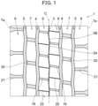
- FIG. 1 shows one example of a development view in which a tread pattern of a tire according to one embodiment of the present invention is developed on a plane.
- a pair of center land parts 6, 6, a pair of middle land parts 7, 7, and a pair of shoulder parts 8, 8 are provided by circumferential grooves 3, 4, and 5 extending continuously in a tire circumferential direction.
- Each center land part 6 is formed between a center circumferential groove 3 and a middle circumferential groove 4.
- Each middle land part 7 is formed between a middle circumferential groove 4 and a shoulder circumferential groove 5.
- Each shoulder land part 8 is formed between a shoulder circumferential groove 5 and a grounding end Te.
- Each center land part 6 is provided with a plurality of center lateral grooves 19 each crossing the center land part 6 and communicating with the center circumferential groove 3 and the middle circumferential groove 4, and independent blocks are formed in each center land part 6.
- Each middle land part 7 is provided with a plurality of middle lateral grooves 20 each crossing the middle land part 7 and communicating with the middle circumferential groove 4 and the shoulder circumferential groove 5, and independent blocks are formed in each middle land part 7.
- Each shoulder land part 8 is provided with a plurality of shoulder lateral grooves 21 each communicating with the shoulder circumferential groove 5.
- the center circumferential grooves 3 extend in zigzag shape. Moreover, each of the center circumferential grooves 3 comprises center long side parts 3A and center short side parts 3B alternating with the center long side parts.
- the center long side parts 3A incline to one side relative to the tire circumferential direction.
- the center short side parts 3B incline in a direction opposite to the direction in which the center long side parts 3A incline.
- center lateral grooves 19 and the middle lateral grooves 20 linearly extend in FIG. 1 , but the present invention is not limited to such an aspect, and they may be those extending, for example, in a wavy, sinusoidal, or zigzag shape.
- Each center land part 6 is provided with a center sipe 22 communicating with the center circumferential groove 3 and the middle circumferential groove 4.
- a center sipe 22 deforms in a direction in which its width is closed when a block edge of the center land part 6 in the tire circumferential direction touches the ground, so that adjacent wall surfaces of the sipe closely adhere to each other for supporting each other, and deterioration of rigidity of a land part can be suppressed.
- the center sipe 22 extends in zigzag shape, but the present invention is not limited to such an aspect, and the center sipe may be one extending, for example, in a wavy or sinusoidal shape or extending linearly.
- a land ratio R in a grounding surface of the tread part is preferably 0.65 or more, more preferably 0.70 or more, further preferably 0.75 or more. Moreover, the land ratio R is preferably 0.95 or less, more preferably 0.90 or less, further preferably 0.85 or less.
- FIG. 2 is a cross-sectional view illustrating a part of a circumferential groove according to the present embodiment.
- a vertical direction is a tire radial direction
- a horizontal direction is a tire axial direction
- a direction perpendicular to a paper surface is a tire circumferential direction.
- the tread part of the tire comprises a first layer 11, a second layer 12, and a third layer 13, wherein an outer surface of the first layer 11 constitutes a tread surface, the second layer 12 is adjacent to the inner side of the first layer 11 in the tire radial direction, and the third layer 13 is present on the inner side of the second layer 12 in the tire radial direction.
- one or two or more rubber layers may be further provided between the second layer 12 and the third layer 13 and/or between the third layer 13 and a belt layer (not shown in the drawings).
- a thickness t1 of the first layer 11 is preferably 5 mm or more, more preferably 8 mm or more, further preferably 10 mm or more, from the viewpoint of the effects of the present invention.
- t1 is preferably 20 mm or less, more preferably 18 mm or less, further preferably 15 mm or less.
- a thickness t2 of the second layer 12 is preferably 1 mm or more, more preferably 3 mm or more, further preferably 5 mm or more, from the viewpoint of the effects of the present invention.
- t2 is preferably 15 mm or less, more preferably 12 mm or less, further preferably 10 mm or less.
- a groove depth H of each of the circumferential grooves is preferably greater than 4 mm, more preferably greater than 7 mm, further preferably greater than 10 mm, particularly preferably greater than 12 mm, from the viewpoint of the effects of the present invention.
- H is preferably less than 26 mm, more preferably less than 24 mm, further preferably less than 22 mm, particularly preferably less than 20 mm.
- the tire according to the present embodiment is formed such that the deepest part of the groove bottom of the circumferential grooves is located on the inner side in the tire radial direction with respect to the outer surface of the second layer 12, and the inner side of each block is formed of two or more rubber layers.
- t1/H is 0.09 or less, preferably 0.85 or less, more preferably 0.80 or less, from the viewpoint of the effects of the present invention.
- a lower limit value of t1/H is, but not particularly limited to, preferably 0.20 or more, more preferably 0.30 or more, further preferably 0.40 or more.
- At least one groove wall of each circumferential groove is preferably provided with a recessed part that is recessed outward in the groove width direction from a groove edge 2 appearing on a grounding face of the tread part.
- a recessed part is provided on the groove wall of the circumferential groove, an air gap is formed inside the tread part, and it is considered that shock can be absorbed and propagation of the shock can be suppressed by the air gap.
- recessed parts 9 are provided on both groove walls 10 of a circumferential groove 3.
- the groove width of the circumferential groove 3 continues to gradually increase from the end on the tire surface side toward the inner side in the tire radial direction, but the present invention is not limited to such an aspect.
- FIG. 3 is a cross-section illustrating a part of another circumferential groove according to the present embodiment.
- a groove width of a circumferential groove 3 is constant in a range of a distance L from the tread surface 14 t and gradually increases therefrom toward the inner side in the tire radial direction, thereby forming a recessed part 9.
- L/t1 is preferably greater than 1.0, more preferably greater than 1.1, further preferably greater than 1.2.
- an upper limit value of L/t1 is, but not particularly limited to, preferably less than 4.0, more preferably less than 3.0, further preferably less than 2.0.
- L is preferably greater than 0 mm, more preferably greater than 5 mm, further preferably greater than 8 mm. On the other hand, L is preferably less than 25 mm, more preferably less than 21 mm, further preferably less than 16 mm.
- a total amount of recession of the circumferential groove 3 (c1 + c2 in FIGS. 2 and 3 ) is preferably 0.10 to 5.00 times, more preferably 0.20 to 3.00 times, further preferably 0.30 to 1.00 times as large as the groove width W1 of the circumferential groove 3.
- a total amount of recession of any one of the circumferential grooves may satisfy the above-described relationship, or all the circumferential grooves each having such a recessed part may satisfy the above-described relationship.
- the tan ⁇ at 70°C (70°C tan ⁇ 1) of the rubber composition constituting the first layer is preferably less than 0.20, more preferably less than 0.16, further preferably less than 0.12, particularly preferably less than 0.10, from the viewpoint of suppressing softening of a rubber due to a rise in temperature of the first layer.
- it is preferably 0.03 or more, more preferably 0.04 or more, further preferably 0.05 or more, from the viewpoint of absorbing deformation due to a road surface.
- a tan ⁇ at 70°C (70°C tan ⁇ 2) of the rubber composition constituting the second layer is preferably greater than 0.07, more preferably greater than 0.09, further preferably greater than 0.10, particularly preferably greater than 0.11, from the viewpoint of making energy to be released by the second layer generating heat when a load is applied to the tire.
- it is preferably 0.30 or less, more preferably 0.25 or less, further preferably 0.20 or less, particularly preferably 0.18 or less, from the viewpoint of suppressing an excessive heat generation inside the block.
- a tan ⁇ at 70°C (70°C tan ⁇ 3) of the rubber composition constituting the third layer is preferably 0.24 or less, more preferably 0.19 or less, further preferably 0.14 or less, particularly preferably 0.09 or less, from the viewpoint of suppressing an excessive heat generation inside the block.
- the 70°C tan ⁇ 3 is preferably 0.03 or more, more preferably 0.04 or more, further preferably 0.05 or more.
- 70°C tan ⁇ 1/70°C tan ⁇ 2 is less than 1.0, preferably less than 0.95, more preferably less than 0.90, further preferably less than 0.85, particularly preferably less than 0.80.
- 70°C tan ⁇ 1/70°C tan ⁇ 2 is within the above-described ranges, energy can be released in a form of heat inside the block, and it is considered that uneven-abrasion resistance can be improved.
- heat generation outside the block is suppressed and a surface of the block part has a high temperature and softens, whereby deterioration of uneven abrasion can be suppressed.
- a lower limit value of 70°C tan ⁇ 1/70°C tan ⁇ 2 is, but not particularly limited to, preferably greater than 0.40, more preferably greater than 0.50, further preferably greater than 0.60.
- 70°C tan ⁇ 2/70°C tan ⁇ 3 is preferably greater than 1.0, more preferably greater than 1.2, further preferably greater than 1.4, further preferably greater than 1.6, particularly preferably greater than 1.8.
- an upper limit value of 70°C tan ⁇ 2/70°C tan ⁇ 3 is, but not particularly limited to, preferably less than 4.0, more preferably less than 3.0.
- 70°C tan ⁇ of each rubber layer can be appropriately adjusted depending on types or compounding amounts of a rubber component, a filler, a softening agent, and the like that are described below.
- a modulus at 200% elongation (M1) of the rubber composition constituting the first layer is preferably 15.0 MPa or less, more preferably 14.0 MPa or less, further preferably 13.0 MPa or less, particularly preferably 12.0 MPa or less.
- a modulus at 200% elongation (M2) of the rubber composition constituting the second layer is preferably 13.0 MPa or less, more preferably 11.0 MPa or less, further preferably 10.0 MPa or less, particularly preferably 9.0 MPa or less.
- each of lower limit values of M1 and M2 is, but not particularly limited to, preferably 2.0 MPa or more, more preferably 3.0 MPa or more, further preferably 4.0 MPa or more.
- a modulus at 200% elongation of the rubber composition constituting the third layer is not particularly limited.
- Elongation at break (EB1) of the rubber composition constituting the first layer is preferably 420% or more, more preferably 440% or more, further preferably 460% or more.
- elongation at break (EB2) of the rubber composition constituting the second layer is preferably 440% or more, more preferably 470% or more, further preferably 500% or more.
- upper limit values of EB1 and EB2 are not particularly limited.
- EB and the modulus at 200% elongation of each rubber layer can be appropriately adjusted depending on types or compounding amounts of the rubber component, filler, softening agent, and the like that are described below.
- a Shore hardness (Hs) of the first layer is preferably 55 or more, more preferably 60 or more, further preferably 65 or more.
- the Shore hardness of the first layer is set to be within the above-described ranges to suppress deformation of the first layer, it is considered that uneven-abrasion resistance can be improved.
- the Shore hardness (Hs) of the first layer is preferably 80 or less, more preferably 75 or less, further preferably 70 or less.
- the Shore hardness can be appropriately adjusted depending on types or compounding amounts of the rubber component, filler, plasticizing agent, and the like.
- a tire outer diameter Dt is preferably 0.70 m or more, more preferably 0.80 m or more, further preferably 0.90 m or more. Moreover, Dt is preferably 1.20 m or less, more preferably 1.10 m or less.
- 70°C tan ⁇ 2/Dt is greater than 0.09, preferably greater than 0.10, more preferably greater than 0.12, further preferably greater than 0.14.
- 70°C tan ⁇ 2/Dt is within the above-described ranges, it is considered that an effect of absorbing deformation inside the tread can be enhanced.
- an upper limit value of 70°C tan ⁇ 2/Dt is, but not particularly limited to, preferably less than 0.24, more preferably less than 0.22.
- 70°C tan ⁇ 1/R is preferably less than 0.150, more preferably less than 0.140, further preferably less than 0.130, further preferably less than 0.120, particularly preferably less than 0.115.
- 70°C tan ⁇ 1/R is within the above-described ranges and the land ratio R is increased with an increase of 70°C tan ⁇ of the first layer, deformation of the first layer is decreased, and it is considered that heat generation is suppressed.
- a lower limit value of 70°C tan ⁇ 1/R is, but not particularly limited to, preferably 0.030 or more, more preferably 0.040 or more, further preferably 0.050 or more, particularly preferably 0.060 or more.
- 70°C tan ⁇ 2/R is preferably 0.100 or more, more preferably 0.130 or more, further preferably 0.150 or more, further preferably 0.160 or more, particularly preferably 0.165 or more.
- an upper limit value of 70°C tan ⁇ 2/R is, but not particularly limited to, preferably 0.270 or less, more preferably 0.230 or less, further preferably 0.200 or less.
- uneven-abrasion resistance can be improved by cooperation of the above-described configurations of the tire and the tread and the above-described physical properties of the rubber composition constituting each layer of the tread part.
- the rubber composition according to the present embodiment will be described below, though the description shall be applicable to any rubber layer of the tread part, unless otherwise noted.
- the rubber composition according to the present embodiment preferably comprises, as a rubber component, at least one selected from the group consisting of an isoprene-based rubber, a styrene-butadiene rubber (SBR), and a butadiene rubber (BR), and more preferably comprises the isoprene-based rubber.
- SBR styrene-butadiene rubber
- BR butadiene rubber
- These rubber components may be used alone, or two or more thereof may be used in combination.
- these rubber components may be modified rubbers each treated with a modified group that can interact with a filler such as carbon black, silica, and the like or may be hydrogenated rubbers for which hydrogeneration treatment is performed on a part of an unsaturated bond.
- Each of the rubber components constituting the first and second layers preferably comprises an isoprene-based rubber and more preferably comprises an isoprene-based rubber and BR.
- isoprene-based rubber those common in the tire industry can be used, such as, for example, an isoprene rubber (IR), a natural rubber, and the like.
- the natural rubber include not only non-modified natural rubbers (NR) but also modified natural rubbers such as an epoxidized natural rubber (ENR), a hydrogenated natural rubber (HNR), a deproteinized natural rubber (DPNR), an ultra pure natural rubber, a grafted natural rubber, and the like.
- ENR epoxidized natural rubber
- HNR hydrogenated natural rubber
- DPNR deproteinized natural rubber
- ultra pure natural rubber a grafted natural rubber, and the like.
- the NR is not particularly limited, and those common in the tire industry can be used, examples of which include, for example, SIR20, RSS#3, TSR20, and the like.
- a content of the isoprene-based rubber in the rubber component is preferably 20% by mass or more, more preferably 30% by mass or more, further preferably 40% by mass or more, particularly preferably 50% by mass or more, from the viewpoint of the effects of the present invention.
- an upper limit value of the content can be, but not particularly limited to, for example, 100% by mass, 99% by mass or less, 95% by mass or less, 90% by mass or less, or 85% by mass or less.
- the BR is not particularly limited, and those common in the tire industry can be used, such as, for example, a BR having a cis content of less than 50% by mass (a low cis BR), a BR having a cis content of 90% by mass or more (a high cis BR), a rare-earth-based butadiene rubber synthesized using a rare-earth element-based catalyst (a rare-earth-based BR), a BR containing a syndiotactic polybutadiene crystal (a SPB-containing BR), a modified BR (a high cis modified BR, a low cis modified BR), and the like. These BRs may be used alone, or two or more thereof may be used in combination.
- a cis content of the high cis BR is preferably 95% by mass or more, more preferably 96% by mass or more, further preferably 97% by mass or more. Besides, the cis content of the BR is measured by the above-described measuring method.
- modified BR a modified butadiene rubber (modified BR) is appropriately used whose terminal and/or main chain are modified with a functional group including at least one element selected from the group consisting of silicon, nitrogen, and oxygen.
- modified BRs examples include those obtained by adding a tin compound after polymerizing 1,3-butadiene by a lithium initiator, a terminal of the modified BR molecule being further bonded by tin-carbon bond (tin-modified BRs), and the like.
- the modified BR may be either non-hydrogenated or hydrogenated.
- a weight-average molecular weight (Mw) of the BR is preferably 300,000 or more, more preferably 350,000 or more, further preferably 400,000 or more, from the viewpoint of abrasion resistance. Moreover, it is preferably 2,000,000 or less, more preferably 1,000,000 or less, from the viewpoints of cross-linking uniformity and the like. Besides, the Mw of the BR can be measured by the above-described measuring method.
- a content of the BR in the rubber component is preferably 50% by mass or less, more preferably 40% by mass or less, further preferably 30% by mass or less, particularly preferably 25% by mass or less, from the viewpoint of the effects of the present invention.
- a lower limit value of the content can be, but not limited to, for example, 1% by mass or more, 3% by mass or more, 5% by mass or more, or 7% by mass or more.
- the SBR is not particularly limited, examples of which include a non-modified solution-polymerized SBR (S-SBR), a non-modified emulsion-polymerized SBR (E-SBR), modified SBRs (a modified S-SBR, a modified E-SBR) thereof, and the like.
- S-SBR solution-polymerized SBR
- E-SBR non-modified emulsion-polymerized SBR
- modified SBR include a SBR modified at its terminal and/or main chain, a modified SBR coupled with tin, a silicon compound, etc. (a modified SBR of condensate or having a branched structure, etc.), and the like.
- the S-SBR and the modified SBR are preferable.
- hydrogenated ones of these SBRs (hydrogenated SBRs) and the like can also be used. These SBRs may be used alone, or two or more thereof may be used in combination.
- An extended SBR or a non-extended SBR may be used as a SBR according to the present embodiment.
- an extending amount of the SBR that is, a content of an extending softening agent in the SBR is preferably 10 to 50 parts by mass based on 100 parts by mass of a rubber solid content of the SBR.
- the SBRs recited above may be used alone, or two or more thereof may be used in combination.
- SBRs recited above for example, those commercially available from Sumitomo Chemical Co., JSR Corporation, Ltd., Asahi Kasei Corporation, Zeon Corporation, ZS Elastomer Co., Ltd., etc. can be used.
- a styrene content of the SBR is preferably 40% by mass or less, more preferably 36% by mass or less, further preferably 32% by mass or less, particularly preferably 28% by mass or less. Moreover, the styrene content of the SBR is preferably 5% by mass or more, more preferably 7% by mass or more, further preferably 10% by mass or more. Besides, the styrene content of the SBR is measured by the above-described measuring method.
- a weight-average molecular weight (Mw) of the SBR is preferably 100,000 or more, more preferably 200,000 or more, further preferably 300,000 or more, from the viewpoint of the effects of the present invention. Moreover, the weight-average molecular weight is preferably 2,000,000 or less, more preferably 1,800,000 or less, further preferably 1,500,000 or less, from the viewpoint of cross-linking uniformity. Besides, the weight-average molecular weight of the SBR is measured by the above-described measurement method.
- a content of the SBR in the rubber component constituting the second layer is preferably 50% by mass or less, more preferably 40% by mass or less, further preferably 30% by mass or less, particularly preferably 20% by mass or less, although it can be appropriately selected, for example, such that a total styrene amount in the rubber component satisfies a range which will be described below.
- a lower limit value of the content can be, but not particularly limited to, for example, 1% by mass or more, 3% by mass or more, 5% by mass or more, or 7% by mass or more.
- contents of the SBR in the rubber components constituting the first and third layers are not particularly limited.
- the total styrene amount in the rubber component constituting the second layer is preferably less than 20% by mass, more preferably less than 16% by mass, further preferably less than 12% by mass, particularly preferably less than 8.0% by mass, from the viewpoint of the effects of the present invention.
- a lower limit value of the total styrene amount in the rubber component constituting the second layer can be, but not particularly limited to, for example, greater than 1.0% by mass, greater than 2.0% by mass, or greater than 3.0% by mass.
- total styrene amounts in the rubber components constituting the first and third layers are not particularly limited.
- the rubber composition may comprise a rubber component other than the above-described isoprene-based rubber, SBR, and BR.
- a cross-linkable rubber component commonly used in the tire industry can be used, examples of which include a diene-based rubber other than the isoprene-based rubber, the SBR, and the BR, such as a styrene-isoprene rubber (SIR), a styrene-isoprene-butadiene rubber (SIBR), a chloroprene rubber (CR), an acrylonitrile-butadiene rubber (NBR), and the like; and a non-diene-based rubber, such as a butyl rubber (IIR), a halogenated butyl rubber, an ethylene propylene rubber, a polynorbornene rubber, a silicone rubber, a polyethylene chloride rubber, a fluororubber (FKM), an acrylic rubber (SIR), styrene-iso
- the rubber component according to the present embodiment comprises preferably 80% by mass or more, more preferably 90% by mass or more, further preferably 95% by mass or more, particularly preferably 98% by mass or more of a diene-based rubber or may be a rubber component consisting of a diene-based rubber. Moreover, it may or may not comprise a known thermoplastic elastomer in addition to the above-described rubber component.
- a filler comprising carbon black and/or silica is appropriately used.
- Each of the rubber compositions constituting the first layer and the second layer comprises, as a filler, preferably carbon black, more preferably carbon black and silica.
- the rubber composition constituting the third layer preferably comprises, as a filler, carbon black.
- Carbon black is not particularly limited, and those common in the tire industry can be used, such as, for example, GPF, FEF, HAF, ISAF, SAF, and the like. Besides, in addition to carbon black generated by burning general mineral oil, carbon black in which a biomass material such as lignin and the like is used, may be used. These carbon black may be used alone, or two or more thereof may be used in combination.
- a nitrogen adsorption specific surface area (N 2 SA) of carbon black contained in the rubber composition constituting the first layer is preferably 70 m 2 /g or more, more preferably 90 m 2 /g or more, further preferably 110 m 2 /g or more, particularly preferably 130 m 2 /g or more, from the viewpoint of reinforcing property. Moreover, it is preferably 200 m 2 /g or less, more preferably 180 m 2 /g or less, further preferably 160 m 2 /g or less, from the viewpoints of fuel efficiency and processability. Besides, the N 2 SA of carbon black is measured by the above-described measuring method.
- a nitrogen adsorption specific surface area (N 2 SA) of carbon black contained in each of the rubber compositions constituting the second layer and the third layer is preferably 10 m 2 /g or more, more preferably 30 m 2 /g or more, further preferably 50 m 2 /g or more, from the viewpoint of reinforcing property. Moreover, it is preferably 200 m 2 /g or less, more preferably 160 m 2 /g or less, further preferably 120 m 2 /g or less, from the viewpoints of fuel efficiency and processability.
- a content of carbon black based on 100 parts by mass of the rubber component is preferably 5 parts by mass or more, more preferably 8 parts by mass or more, further preferably 15 parts by mass or more, particularly preferably 25 parts by mass or more, from the viewpoint of reinforcing property. Moreover, the content is preferably 90 parts by mass or less, more preferably 80 parts by mass or less, further preferably 70 parts by mass or less, particularly preferably 60 parts by mass or less.
- Silica is not particularly limited, and those common in the tire industry can be used, such as, for example, silica prepared by a dry process (anhydrous silica), silica prepared by a wet process (hydrous silica), and the like. Among them, hydrous silica prepared by a wet process is preferable for the reason that it has many silanol groups. Besides, in addition to the above-described silica, silica made from a biomass material such as rice husks and the like may be appropriately used. These silica may be used alone, or two or more thereof may be used in combination.
- a nitrogen adsorption specific surface area (N 2 SA) of silica is preferably 120 m 2 /g or more, more preferably 150 m 2 /g or more, further preferably 170 m 2 /g or more, from the viewpoints of fuel efficiency and abrasion resistance. Moreover, it is preferably 350 m 2 /g or less, more preferably 300 m 2 /g or less, further preferably 250 m 2 /g or less, from the viewpoints of fuel efficiency and processability. Besides, the N 2 SA of silica is measured by the above-described measuring method.
- a content of silica based on 100 parts by mass of each of the rubber components of the rubber compositions constituting the first and second layers is preferably 3 parts by mass or more, more preferably 5 parts by mass or more, further preferably 10 parts by mass or more, particularly preferably 15 parts by mass or more, from the viewpoint of the effects of the present invention. Moreover, the content is preferably 90 parts by mass or less, more preferably 80 parts by mass or less, further preferably 70 parts by mass or less, particularly preferably 60 parts by mass or less. Besides, a content of silica based on 100 parts by mass of the rubber component of the rubber composition constituting the third layer is not particularly limited.
- Fillers other than silica and carbon black are not particularly limited, and those conventionally and commonly used in the tire industry can be compounded, such as, for example, aluminum hydroxide, alumina (aluminum oxide), calcium carbonate, magnesium sulfate, talc, clay, biochar, and the like. These other fillers may be used alone, or two or more thereof may be used in combination.
- a total content of fillers based on 100 parts by mass of the rubber component is preferably 25 parts by mass or more, more preferably 30 parts by mass or more, further preferably 35 parts by mass or more, particularly preferably 40 parts by mass or more. Moreover, the total content is preferably 150 parts by mass or less, more preferably 130 parts by mass or less, further preferably 110 parts by mass or less, particularly preferably 90 parts by mass or less.
- a mass content ratio of silica to carbon black in the rubber composition constituting the second layer is preferably 0.30 or more, more preferably 0.40 or more, further preferably 0.50 or more, particularly preferably 0.75 or more, particularly preferably greater than 1.0.
- the mass content ratio is preferably 20 or less, more preferably 15 or less, further preferably 10 or less, particularly preferably 5.0 or less, from the viewpoint of the effects of the present invention.
- a mass content ratio of silica to carbon black in each of the rubber compositions constituting the first layer and the third layer is not particularly limited.
- Silica is preferably used in combination with a silane coupling agent.
- the silane coupling agent is not particularly limited, and any silane coupling agent conventionally used in combination with silica in the tire industry can be used, such as, for example, mercapto-based silane coupling agents such as 3-mercaptopropyltrimethoxysilane, 3-mercaptopropyltriethoxysilane, 2-mercaptoethyltrimethoxysilane, 2-mercaptoethyltriethoxysilane, and the like; sulfide-based silane coupling agents such as bis(3-triethoxysilylpropyl)disulfide, bis(3-triethoxysilylpropyl)tetrasulfide, and the like; thioester-based silane coupling agents such as 3-octanoylthio-1-propyltriethoxysilane, 3-hexanoylthio-1-propyltrie
- a sulfide-based silane coupling agent and/or a mercapto-based silane coupling agent are preferably compounded in the rubber composition.
- the silane coupling agent for example, those commercially available from Momentive Performance Materials, etc. can be used. These silane coupling agents may be used alone, or two or more thereof may be used in combination.
- a content of the silane coupling agent based on 100 parts by mass of silica preferably 1.0 part by mass or more, more preferably 3.0 parts by mass or more, further preferably 5.0 parts by mass or more, from the viewpoint of enhancing dispersibility of silica. Moreover, it is preferably 20 parts by mass or less, more preferably 15 parts by mass or less, further preferably 12 parts by mass or less, from the viewpoints of cost and processability.
- the rubber composition according to the present embodiment can appropriately comprise compounding agents conventionally and commonly used in the tire industry, such as, for example, a softening agent, wax, stearic acid, zinc oxide, an antioxidant, a vulcanizing agent, a vulcanization accelerator, and the like, in addition to the above-described components.
- compounding agents conventionally and commonly used in the tire industry, such as, for example, a softening agent, wax, stearic acid, zinc oxide, an antioxidant, a vulcanizing agent, a vulcanization accelerator, and the like, in addition to the above-described components.
- softening agent examples include, for example, a resin component, oil, a liquid polymer, and the like.
- the resin component examples include, but not particularly limited to, hydrocarbon resins, such as a petroleum resin, a terpene-based resin, a rosin-based resin, a phenol-based resin, and the like, which are commonly used in the tire industry. These resin components may be used alone, or two or more thereof may be used in combination.
- Examples of the petroleum resin include a C5-based petroleum resin, an aromatic petroleum resin, a C5-C9-based petroleum resin, and the like.
- C5-based petroleum resin means a resin obtained by polymerizing C5 fractions and may be those undergoing hydrogeneration or modification.
- C5 fractions include, for example, petroleum fractions having 4 to 5 carbon atoms, such as cyclopentadiene, pentene, pentadiene, isoprene, and the like.
- Dicyclopentadiene resin DCPD resin
- C5-based petroleum resin is appropriately used as a C5-based petroleum resin.
- the "aromatic petroleum resin” means a resin obtained by polymerizing C9 fractions and may be those undergoing hydrogeneration or modification.
- C9 fractions include, for example, petroleum fractions having 8 to 10 carbon atoms, such as vinyltoluene, alkylstyrene, indene, methylindene, and the like.
- aromatic petroleum resin for example, a coumarone-indene resin, a coumarone resin, an indene resin, and an aromatic vinyl-based resin are appropriately used.
- aromatic vinyl-based resin a homopolymer of ⁇ -methylstyrene or styrene or a copolymer of ⁇ -methylstyrene and styrene is preferable, and the copolymer of ⁇ -methylstyrene and styrene is more preferable, because it is economical, easy to process, and excellent in heat generation.
- aromatic vinyl-based resin for example, those commercially available from Kraton Corporation, Eastman Chemical Company, etc. can be used.
- C5-C9-based petroleum resin means a resin obtained by polymerizing the C5 fractions and the C9 fractions and may be those undergoing hydrogeneration or modification.
- Examples of C5 fractions and C9 fractions include the above-described petroleum fractions.
- the C5-C9-based petroleum resin for example, those commercially available from Tosoh Corporation, Zibo Luhua Hongjin New Material Co., Ltd., etc. can be used.
- terpene-based resin examples include a polyterpene resin consisting of at least one selected from terpene compounds such as ⁇ -pinene, ⁇ -pinene, limonene, dipentene, and the like; an aromatic modified terpene resin made from a terpene compound described above and an aromatic compound; a terpene phenol resin made from a terpene compound and a phenol-based compound; and a resin obtained by hydrogenating these types of terpene-based resin (hydrogenated terpene-based resin).
- terpene resin consisting of at least one selected from terpene compounds such as ⁇ -pinene, ⁇ -pinene, limonene, dipentene, and the like
- an aromatic modified terpene resin made from a terpene compound described above and an aromatic compound
- a terpene phenol resin made from a terpene compound and a phenol-based compound
- aromatic compound from which the aromatic modified terpene resin is made examples include, for example, styrene, ⁇ -methylstyrene, vinyltoluene, divinyltoluene, and the like.
- phenol-based compound from which the terpene phenol resin is made examples include, for example, phenol, bisphenol A, cresol, xylenol, and the like.
- rosin-based resin examples include, but not particularly limited to, for example, a natural resin rosin; a rosin-modified resin obtained by modifying it by hydrogenation, disproportionation, dimerization, or esterification, or the like; and the like.
- phenol-based resin examples include, but not particularly limited to, a phenol formaldehyde resin, an alkylphenol formaldehyde resin, an alkylphenol acetylene resin, an oil-modified phenol formaldehyde resin, and the like.
- a softening point of the resin component is preferably 60 °C or higher, more preferably 70°C or higher, further preferably 80°C or higher, from the viewpoint of grip performance. Moreover, it is preferably 150 °C or lower, more preferably 140 °C or lower, further preferably 130 °C or lower, from the viewpoints of processability and improvement in dispersibility of the rubber component with the filler. Besides, the softening point of the resin component is measured by the above-described measuring method.
- a content of the resin component when compounded based on 100 parts by mass of the rubber component is preferably greater than 1.0 part by mass, more preferably greater than 1.5 parts by mass. Moreover, it is preferably less than 50 parts by mass, more preferably less than 40 parts by mass, further preferably less than 30 parts by mass, from the viewpoint of suppression of heat generation.
- oils examples include, for example, process oils, vegetable oils and fats, animal oils and fats, and the like.
- process oils include paraffinic process oils (mineral oils), naphthenic process oils, aromatic process oils, and the like.
- Specific examples of the process oils include, for example, MES (Mild Extract Solvated), DAE (Distillate Aromatic Extract), TDAE (Treated Distillate Aromatic Extract), TRAE (Treated Residual Aromatic Extract), RAE (Residual Aromatic Extract), and the like.
- MES Metal Extract Solvated
- DAE Dynamic Extract
- TDAE Transmission Distillate Aromatic Extract
- TRAE Tereated Residual Aromatic Extract
- RAE Residual Aromatic Extract
- a process oil having a low content of a polycyclic aromatic compound (PCA) can also be used for environmental measures.
- Examples of the process oil having a low PCA content include the MES, the TDAE, a heavy naphthenic oil, and the like. Moreover, from the viewpoint of a life cycle assessment, one obtained by refining a waste oil after use for a rubber mixing machine or an engine or waste cooking oil used in a cooking facility may be used.
- a content of oil when compounded based on 100 parts by mass of the rubber component is preferably greater than 1 part by mass, more preferably greater than 3 parts by mass, further preferably greater than 5 parts by mass, from the viewpoint of processability. Moreover, it is preferably less than 90 parts by mass, more preferably less than 70 parts by mass, further preferably less than 50 parts by mass, particularly preferably less than 30 parts by mass, from the viewpoint of abrasion resistance.
- the liquid polymer is not particularly limited as long as it is a polymer in a liquid state at a normal temperature (25°C), examples of which include, for example, a liquid butadiene polymer (liquid BR), a liquid isoprene rubber polymer (liquid IR), a liquid styrene-butadiene copolymer (liquid SBR), a liquid styrene-isoprene rubber copolymer (liquid SIR), a copolymer including myrcene farnesene, and the like.
- liquid BR liquid butadiene polymer
- liquid IR liquid isoprene rubber polymer
- SBR liquid styrene-butadiene copolymer
- liquid SIR liquid styrene-isoprene rubber copolymer
- copolymer including myrcene farnesene and the like.
- a content of the liquid polymer when compounded based on 100 parts by mass of the rubber component is preferably greater than 1 part by mass, more preferably greater than 3 parts by mass, further preferably greater than 5 parts by mass. Moreover, the content of the liquid polymer is preferably less than 50 parts by mass, more preferably less than 40 parts by mass, further preferably less than 30 parts by mass.
- a content of the softening agent based on 100 parts by mass of the rubber component is, but not particularly limited to, preferably greater than 1.0 part by mass, more preferably greater than 1.5 parts by mass, further preferably greater than 2.0 parts by mass. Moreover, the content is preferably less than 90 parts by mass, more preferably less than 70 parts by mass, further preferably less than 50 parts by mass, particularly preferably less than 30 parts by mass.
- the wax is not particularly limited, and any of those commonly used in the tire industry can be appropriately used, examples of which include, for example, a petroleum-based wax, a mineral-based wax, a synthetic wax, and the like.
- the petroleum-based wax is preferable.
- Examples of the petroleum-based wax include, for example, a paraffin wax, a microcrystalline wax, a selected special wax thereof, and the like.
- the paraffin wax is preferable.
- the wax according to the present embodiment shall not include stearic acid.
- a wax for example, those commercially available from Ouchi Shinko Chemical Industry Co., Nippon Seiro Co., Ltd., PARAMELT, etc. can be used. These waxes may be used alone, or two or more thereof may be used in combination.
- a content of wax when compounded based on 100 parts by mass of the rubber component is preferably greater than 0.5 parts by mass, more preferably greater than 0.8 parts by mass, from the viewpoint of weather resistance of a rubber. Moreover, it is preferably less than 10 parts by mass, more preferably less than 5.0 parts by mass, from the viewpoint of prevention of whitening of a tire due to bloom.
- antioxidants include, but not particularly limited to, for example, amine-based, quinoline-based, quinone-based, phenol-based, and imidazole-based compounds, and antioxidants such as a carbamic acid metal salt and the like, preferably phenylenediamine-based antioxidants such as N-(1,3-dimethylbutyl)-N'-phenyl-p-phenylenediamine, N-isopropyl-N'-phenyl-p-phenylenediamine, N,N'-diphenyl-p-phenylenediamine, N,N'-di-2-naphthyl-p-phenylenediamine, N-cyclohexyl-N'-phenyl-p-phenylenediamine, and the like; and quinoline-based antioxidants such as 2,2,4-trimethyl-1,2-dihydroquinoline polymer, 6-ethoxy-2,2,4-trimethyl-1,2-dihydroquinoline, and
- a content of the antioxidant when compounded based on 100 parts by mass of the rubber component is preferably greater than 0.5 parts by mass, more preferably greater than 0.8 parts by mass, from the viewpoint of ozone crack resistance of a rubber. Moreover, it is preferably less than 10 parts by mass, more preferably less than 5.0 parts by mass, from the viewpoint of abrasion resistance.
- a content of stearic acid when compounded based on 100 parts by mass of the rubber component is preferably greater than 0.5 parts by mass, more preferably greater than 1.0 part by mass, further preferably greater than 1.5 parts by mass, from the viewpoint of processability. Moreover, it is preferably less than 10 parts by mass, more preferably less than 5.0 parts by mass, from the viewpoint of vulcanization rate.
- a content of zinc oxide when compounded based on 100 parts by mass of the rubber component is preferably greater than 0.5 parts by mass, more preferably greater than 1.0 part by mass, further preferably greater than 1.5 parts by mass, from the viewpoint of processability. Moreover, it is preferably less than 10 parts by mass, more preferably less than 5.0 parts by mass, from the viewpoint of abrasion resistance.
- Sulfur is appropriately used as a vulcanizing agent.
- sulfur a powdered sulfur, an oil processing sulfur, a precipitated sulfur, a colloidal sulfur, an insoluble sulfur, a highly dispersible sulfur, and the like can be used.
- a content of sulfur when compounded as a vulcanizing agent based on 100 parts by mass of the rubber component is preferably greater than 0.1 parts by mass, more preferably greater than 0.5 parts by mass, further preferably greater than 1.0 part by mass, from the viewpoint of securing a sufficient vulcanization reaction. Moreover, it is preferably less than 5.0 parts by mass, more preferably less than 4.0 parts by mass, further preferably less than 3.5 parts by mass, from the viewpoint of prevention of deterioration.
- a content of the vulcanizing agent in a case where an oil-containing sulfur is used as the vulcanizing agent shall be a total content of pure sulfur contained in the oil-containing sulfur.
- vulcanizing agents other than sulfur include, for example, an alkylphenol-sulfur chloride condensate, sodium hexamethylene-1,6-bisthiosulfate dihydrate, 1,6-bis(N,N'-dibenzylthiocarbamoyl dithio)hexane, and the like.
- vulcanizing agents other than sulfur those commercially available from Taoka Chemical Co., Ltd., LANXESS, Flexsys, etc. can be used.
- vulcanization accelerator examples include, for example, a sulfenamide-based vulcanization accelerator, a thiazole-based vulcanization accelerator, a thiuram-based vulcanization accelerator, a guanidine-based vulcanization accelerator, a dithiocarbamic acid salt-based vulcanization accelerator, caprolactam disulfide, and the like. These vulcanization accelerators may be used alone, or two or more thereof may be used in combination.
- one or more vulcanization accelerators selected from the group consisting of the sulfenamide-based vulcanization accelerator, the thiazole-based vulcanization accelerator, and the guanidine-based vulcanization accelerator are preferable, and the sulfenamide-based vulcanization accelerator and the guanidine-based vulcanization accelerator are more preferably used in combination.
- sulfenamide-based vulcanization accelerator examples include, for example, N-tert-butyl-2-benzothiazolyl sulfenamide (TBBS), N-cyclohexyl-2-benzothiazolyl sulfenamide (CBS), N,N-dicyclohexyl-2-benzothiazolyl sulfenamide (DCBS), and the like.
- TBBS N-tert-butyl-2-benzothiazolyl sulfenamide
- CBS N-cyclohexyl-2-benzothiazolyl sulfenamide
- DCBS N,N-dicyclohexyl-2-benzothiazolyl sulfenamide
- TBBS and CBS are preferable.
- thiazole-based vulcanization accelerator examples include, for example, 2-mercaptobenzothiazole (MBT) or a salt thereof, di-2-benzothiazolyl disulfide (MBTS), 2-(2,4-dinitrophenyl) mercaptobenzothiazole, 2-(2,6-diethyl-4-morpholinothio) benzothiazole, and the like.
- MBT 2-mercaptobenzothiazole
- MBTS di-2-benzothiazolyl disulfide
- 2-(2,4-dinitrophenyl) mercaptobenzothiazole 2-(2,6-diethyl-4-morpholinothio) benzothiazole
- the MBTS and MBT are preferable, and the MBTS is more preferable.
- Examples of the guanidine-based vulcanization accelerator include, for example, 1,3-diphenylguanidine (DPG), 1,3-di-o-tolylguanidine, 1-o-tolylbiguanide, di-o-tolylguanidine salt of dicatecholborate, 1,3-di-o-cumenyl guanidine, 1,3-di-o-biphenyl guanidine, 1,3-di-o-cumenyl-2-propionyl guanidine, and the like.
- DPG 1,3-diphenylguanidine
- 1,3-di-o-tolylguanidine 1,3-di-o-tolylguanidine, 1-o-tolylbiguanide
- di-o-tolylguanidine salt of dicatecholborate 1,3-di-o-cumenyl guanidine
- 1,3-di-o-biphenyl guanidine 1,3-di-
- a content of the vulcanization accelerator when compounded based on 100 parts by mass of the rubber component is preferably greater than 0.5 parts by mass, more preferably greater than 1.0 part by mass, further preferably greater than 1.5 parts by mass. Moreover, the content of the vulcanization accelerator based on 100 parts by mass of the rubber component is preferably less than 8.0 parts by mass, more preferably less than 6.0 parts by mass, further preferably less than 4.0 parts by mass. When the content of the vulcanization accelerator is within the above-described ranges, there is a tendency to be able to secure breaking strength and elongation.
- the rubber composition according to the present embodiment can be produced by a known method.
- it can be produced by kneading the respective above-described components with a rubber kneading machine such as an open roll, a sealed type kneader (a Banbury mixer, a kneader, and the like), and the like.
- a rubber kneading machine such as an open roll, a sealed type kneader (a Banbury mixer, a kneader, and the like), and the like.
- the kneading step includes, for example, a base kneading step of kneading compounding agents and additives other than a vulcanizing agent and a vulcanization accelerator; and a final kneading (F-kneading) step of adding the vulcanizing agent and the vulcanization accelerator to the kneaded product obtained in the base kneading step and kneading them.
- the base kneading step can also be divided into multiple steps as necessary.
- Examples of kneading conditions include, but not particularly limited to, for example, a method of kneading at a discharge temperature of 150 °C to 170°C for 3 to 10 minutes in the base kneading step and kneading at 70°C to 110°C for 1 to 5 minutes in the final kneading step.
- Examples of vulcanization conditions include, but not particularly limited to, for example, a method of vulcanizing at 150 °C to 200°C for 10 to 30 minutes.
- the tire comprising the tread including the first layer 11, the second layer 12, and the third layer 13 can be produced using the above-described rubber compositions by a usual method. That is, the tire can be produced by extruding unvulcanized rubber compositions, in which the above-described components are compounded for rubber components as appropriate, into shapes of the first layer 11, the second layer 12, and the third layer 13 with an extruder equipped with a mouthpiece having a predetermined shape, attaching them together with other tire members on a tire forming machine, and molding them by a usual method to form an unvulcanized tire, followed by heating and pressurizing this unvulcanized tire in a vulcanizing machine.
- vulcanization conditions include, but not particularly limited to, for example, a method of vulcanizing at 150 °C to 200 °C for 10 to 30 minutes.
- the tire according to the present embodiment can be appropriately used as a heavy duty tire.
- the heavy duty tire refers to a tire that is presupposed to be mounted to a vehicle running with four wheels and that has a maximum load capacity of 1000 kg or more.
- the maximum load capacity of the heavy duty tire is preferably 1200 kg or more, more preferably 1400 kg or more.
- the unvulcanized rubber compositions are molded into shapes of a first layer, a second layer (thicknesses: 10 mm), and a third layer (thickness: 3 mm) of a tread and attached together with other tire members to produce an unvulcanized tire, and the unvulcanized tire is vulcanized at 150°C, thereby obtaining each test tire listed in Table 2 and Table 3.
- the groove widths W1 of circumferential grooves are set to be 5mm and a total amount of recession of the circumferential grooves is set to be 2 mm.
- a tan ⁇ is measured using a dynamic viscoelasticity measuring apparatus (EPLEXOR series manufactured by gabo Systemtechnik GmbH) under a condition of a temperature at 70°C, a frequency of 10 Hz, an initial strain of 10%, a dynamic strain of 1%, and an extension mode.
- EPLEXOR series manufactured by gabo Systemtechnik GmbH EPLEXOR series manufactured by gabo Systemtechnik GmbH
- dumbbell-shaped test piece having a thickness of 1 mm which is cut out from the inner side of each rubber layer of the tread part of each test tire such that the tire circumferential direction becomes a tensile direction and the tire radial direction becomes a thickness direction
- a tensile test is performed in accordance with JIS K 6251: 2017 under an atmosphere at 23°C under a condition of a tension rate of 3.3 mm/sec, and each of elongation at break EB (%) and a modulus at 200% elongation (MPa) is measured.
- a Shore hardness (Hs) at 23°C of each rubber test piece is measured in accordance with JIS K 6253-3:2012 using a type A durometer.
- Each test tire is mounted on all wheels of a truck (2-D vehicle) with a maximum loading capacity of 10 tons. After the truck is made run for 10000 km at an average speed of 80 km/hour on a test course with a dry asphalt road surface, a difference between amounts of abrasion on both sides of each of a center block, a middle block, and a shoulder block of a rear wheel in a tire circumferential direction is measured. In the measurement, for each block, eight blocks having an approximately equal pitch in the tire circumferential direction are used and an average value of all measurement values are calculated. Additionally, measurement results are indicated as indexes by the following calculation equation. The results show that the larger the index is, the better the uneven-abrasion resistance is.
- control tires are Comparative example 3 in Table 2 and Comparative example 10 in Table 3.
- Uneven-abrasion resistance index Difference between amounts of abrasion of control tire / Difference between amounts of abrasion of each test tire ⁇ 100 Table 1 Rubber layer 1 2 3 4 5 6 7 8 9 10 11 Compounding amount (part by mass) NR 80 70 80 90 70 50 70 50 80 90 100 SBR - - - - 15 30 - 30 - - - BR 20 30 20 10 15 20 30 20 20 10 - Compounding amount (part by mass) Carbon black 1 35 20 - 48 - - 53 26 - 8 - Carbon black 2 - 30 48 - 50 55 - - 10 - - Carbon black 3 - - - - - - - - - - - 42 Silica 15 - - 5 - - - 35 45 40 - Silane coupling agent 1.5 - - - - - - 35 45 40 - Silane coupling agent 1.5 - -
Landscapes
- Engineering & Computer Science (AREA)
- Mechanical Engineering (AREA)
- Tires In General (AREA)
- Compositions Of Macromolecular Compounds (AREA)
Applications Claiming Priority (1)
| Application Number | Priority Date | Filing Date | Title |
|---|---|---|---|
| JP2022136322A JP2024032596A (ja) | 2022-08-29 | 2022-08-29 | 重荷重用タイヤ |
Publications (1)
| Publication Number | Publication Date |
|---|---|
| EP4331868A1 true EP4331868A1 (de) | 2024-03-06 |
Family
ID=87556250
Family Applications (1)
| Application Number | Title | Priority Date | Filing Date |
|---|---|---|---|
| EP23189444.5A Pending EP4331868A1 (de) | 2022-08-29 | 2023-08-03 | Schwerlastreifen |
Country Status (2)
| Country | Link |
|---|---|
| EP (1) | EP4331868A1 (de) |
| JP (1) | JP2024032596A (de) |
Citations (4)
| Publication number | Priority date | Publication date | Assignee | Title |
|---|---|---|---|---|
| JP2007126523A (ja) | 2005-11-01 | 2007-05-24 | Toyo Tire & Rubber Co Ltd | 空気入りタイヤ |
| US20120234442A1 (en) * | 2011-03-17 | 2012-09-20 | Societe De Technologie Michelin | Tread having a gradient of properties for improving irregular wear |
| US20120298271A1 (en) * | 2009-11-26 | 2012-11-29 | Michelin Recherche Et Technique S.A. | Tire for a vehicle carrying heavy loads |
| US20210395499A1 (en) * | 2020-06-17 | 2021-12-23 | Sumitomo Rubber Industries, Ltd. | Tire |
-
2022
- 2022-08-29 JP JP2022136322A patent/JP2024032596A/ja active Pending
-
2023
- 2023-08-03 EP EP23189444.5A patent/EP4331868A1/de active Pending
Patent Citations (4)
| Publication number | Priority date | Publication date | Assignee | Title |
|---|---|---|---|---|
| JP2007126523A (ja) | 2005-11-01 | 2007-05-24 | Toyo Tire & Rubber Co Ltd | 空気入りタイヤ |
| US20120298271A1 (en) * | 2009-11-26 | 2012-11-29 | Michelin Recherche Et Technique S.A. | Tire for a vehicle carrying heavy loads |
| US20120234442A1 (en) * | 2011-03-17 | 2012-09-20 | Societe De Technologie Michelin | Tread having a gradient of properties for improving irregular wear |
| US20210395499A1 (en) * | 2020-06-17 | 2021-12-23 | Sumitomo Rubber Industries, Ltd. | Tire |
Also Published As
| Publication number | Publication date |
|---|---|
| JP2024032596A (ja) | 2024-03-12 |
Similar Documents
| Publication | Publication Date | Title |
|---|---|---|
| EP3950381B1 (de) | Reifen | |
| EP4067114B1 (de) | Reifen | |
| EP3950386B1 (de) | Reifen | |
| EP3798258A2 (de) | Reifen lauffläche | |
| EP3950387B1 (de) | Reifen | |
| EP3995323B1 (de) | Reifen | |
| EP4052927A1 (de) | Reifen | |
| WO2021256124A1 (ja) | タイヤ | |
| EP4331868A1 (de) | Schwerlastreifen | |
| EP4371782A1 (de) | Reifen | |
| EP4335657A1 (de) | Reifen | |
| EP4331869A1 (de) | Reifen | |
| EP4371781A1 (de) | Reifen | |
| EP4289633A1 (de) | Reifen | |
| EP4335658A1 (de) | Reifen | |
| EP4275917A1 (de) | Reifen | |
| EP4357154A1 (de) | Reifen | |
| EP4190587A1 (de) | Reifen | |
| EP3954550B1 (de) | Luftreifen | |
| EP4227358A1 (de) | Kautschukzusammensetzung und reifen | |
| EP4368412A1 (de) | Reifen | |
| EP4169739A1 (de) | Reifen | |
| EP4265436A1 (de) | Motorradreifen | |
| EP4299339A1 (de) | Schwerlastreifen | |
| EP4316869A1 (de) | Kautschukzusammensetzung für reifen und reifen |
Legal Events
| Date | Code | Title | Description |
|---|---|---|---|
| PUAI | Public reference made under article 153(3) epc to a published international application that has entered the european phase |
Free format text: ORIGINAL CODE: 0009012 |
|
| STAA | Information on the status of an ep patent application or granted ep patent |
Free format text: STATUS: THE APPLICATION HAS BEEN PUBLISHED |
|
| AK | Designated contracting states |
Kind code of ref document: A1 Designated state(s): AL AT BE BG CH CY CZ DE DK EE ES FI FR GB GR HR HU IE IS IT LI LT LU LV MC ME MK MT NL NO PL PT RO RS SE SI SK SM TR |