EP4331506B1 - Device for ligating tissue - Google Patents
Device for ligating tissue Download PDFInfo
- Publication number
- EP4331506B1 EP4331506B1 EP23194927.2A EP23194927A EP4331506B1 EP 4331506 B1 EP4331506 B1 EP 4331506B1 EP 23194927 A EP23194927 A EP 23194927A EP 4331506 B1 EP4331506 B1 EP 4331506B1
- Authority
- EP
- European Patent Office
- Prior art keywords
- tubular element
- flexible
- arms
- control wire
- target tissue
- Prior art date
- Legal status (The legal status is an assumption and is not a legal conclusion. Google has not performed a legal analysis and makes no representation as to the accuracy of the status listed.)
- Active
Links
Images

Classifications
-
- A—HUMAN NECESSITIES
- A61—MEDICAL OR VETERINARY SCIENCE; HYGIENE
- A61B—DIAGNOSIS; SURGERY; IDENTIFICATION
- A61B17/00—Surgical instruments, devices or methods
- A61B17/12—Surgical instruments, devices or methods for ligaturing or otherwise compressing tubular parts of the body, e.g. blood vessels or umbilical cord
- A61B17/122—Clamps or clips, e.g. for the umbilical cord
-
- A—HUMAN NECESSITIES
- A61—MEDICAL OR VETERINARY SCIENCE; HYGIENE
- A61B—DIAGNOSIS; SURGERY; IDENTIFICATION
- A61B17/00—Surgical instruments, devices or methods
- A61B17/12—Surgical instruments, devices or methods for ligaturing or otherwise compressing tubular parts of the body, e.g. blood vessels or umbilical cord
- A61B17/128—Surgical instruments, devices or methods for ligaturing or otherwise compressing tubular parts of the body, e.g. blood vessels or umbilical cord for applying or removing clamps or clips
- A61B17/1285—Surgical instruments, devices or methods for ligaturing or otherwise compressing tubular parts of the body, e.g. blood vessels or umbilical cord for applying or removing clamps or clips for minimally invasive surgery
-
- A—HUMAN NECESSITIES
- A61—MEDICAL OR VETERINARY SCIENCE; HYGIENE
- A61B—DIAGNOSIS; SURGERY; IDENTIFICATION
- A61B17/00—Surgical instruments, devices or methods
- A61B17/00234—Surgical instruments, devices or methods for minimally invasive surgery
- A61B2017/00292—Surgical instruments, devices or methods for minimally invasive surgery mounted on or guided by flexible, e.g. catheter-like, means
- A61B2017/0034—Surgical instruments, devices or methods for minimally invasive surgery mounted on or guided by flexible, e.g. catheter-like, means adapted to be inserted through a working channel of an endoscope
-
- A—HUMAN NECESSITIES
- A61—MEDICAL OR VETERINARY SCIENCE; HYGIENE
- A61B—DIAGNOSIS; SURGERY; IDENTIFICATION
- A61B17/00—Surgical instruments, devices or methods
- A61B2017/00743—Type of operation; Specification of treatment sites
- A61B2017/00818—Treatment of the gastro-intestinal system
-
- A—HUMAN NECESSITIES
- A61—MEDICAL OR VETERINARY SCIENCE; HYGIENE
- A61B—DIAGNOSIS; SURGERY; IDENTIFICATION
- A61B90/00—Instruments, implements or accessories specially adapted for surgery or diagnosis and not covered by any of the groups A61B1/00 - A61B50/00, e.g. for luxation treatment or for protecting wound edges
- A61B90/03—Automatic limiting or abutting means, e.g. for safety
- A61B2090/037—Automatic limiting or abutting means, e.g. for safety with a frangible part, e.g. by reduced diameter
Definitions
- a device for closing or ligating tissue at the inner wall of a hollow organ such as the digestive tract or other body lumens and hollow organs is provided which is relatively simple to manufacture and use.
- Examples of available devices include tools of the type: " Endoloop ®” or " Polyloop ® ", with difficult positioning due to excessive flexibility of its loop and a complex tightening and separation system.
- the document FR-3 117 327 A relates to an improved device comprising a first and a second arm, a clamping wire connecting the two distal ends of the first and second arms, a flexible control wire passing through a slot, said flexible control wire having at its end a loop surrounding said clamping wire, a projection for retaining the loop and allowing the clamping wire to be fixed in the pulling position and a rigid control wire positioned in a notch.
- the space between the arms is however not clear.
- the present invention therefore aims to remedy these drawbacks: to have a simple tool, which is used in the working channel of an endoscope.
- This device has two rigid arms allowing its easy positioning around the lesion or target tissue area with a predefined clamping force allowing the closure or ligation of the target tissue in an effective and durable manner, it is used by simple introduction into the working channel of the endoscope.
- This device comprises an elongated, flexible tubular element 1, used through a working channel of an endoscope, a proximal end of which remains external to the body, accessible to a user with a joystick (control handle) while a distal end 2 of the flexible element is inserted into the hollow organ after its introduction into the working channel of the endoscope to a location adjacent to the target tissue to be closed or ligated.
- Said device also comprises two control wires, a flexible control wire 9 and a rigid control wire 13 extending through the flexible element 1, the two wires being removably coupled to the device.
- Said device can be made of an insulating material that is not conductive to electrical current (plastic type), for example in the case of resection of ligated tissue with a coagulation section current, or of a conductive material (of electrical current), for example in the case of resection of cold ligated tissue or in the case of use of the device only for closing the tissue.
- plastic type for example in the case of resection of ligated tissue with a coagulation section current
- a conductive material of electrical current
- This device comprises a first 3 and a second 4 arm of a predefined length, the distal end of the second arm 4 is connected by a flexible tightening wire 5 with a predefined length, said flexible tightening wire 5 being able to be made of a predefined resorbable or non-resorbable material.
- the other end of the flexible tightening wire 5 is fixed on the external edge 6 of the distal end of the first arm 3, a loop 7 of said flexible tightening wire 5 passes from the external side into the slot 8 of the distal end of the first arm 3.
- the flexible wire 9 passes through a slot 10 at the proximal portion of the device. Said wire 9 then passes through the loop 7 of the wire 5. Said wire 9 has at its end a loop 11 of predefined size. The loop 11 of the end of the flexible wire 9 is retained on a projection 12 at the proximal end of the device.
- the proximal portion 18 of the device is secured by the distal end 17 of the rigid control wire 13 positioned in a frangible connection 14.
- the curved projection 15 retains the distal end 17 of the rigid control wire 13 in the frangible connection which fails when the device is fully exited from the distal end 2 of the flexible member 1 to separate the device from the tether of the rigid control wire 13.
- An actuator at the proximal end of the flexible member 1 coupled to the rigid control wire 13 and configured to move the device into the end of the flexible member 1 until the first 3 and second 4 arms of the device exit into an open position and its withdrawal into the distal end of the flexible member 1 for a closed configuration.
- the first 3 and second 4 arms of the device have a predefined proximal angulation 16 allowing the two ends of the first 3 and second 4 arms of the device to be separated once they have exited the distal end of the flexible element 1. In the open configuration, the distal ends of the first 3 and second 4 arms of the device are separated, allowing the device to be positioned on the target tissue area to be grasped. In a variant of the embodiments, the first 3 and second 4 arms of the device contain a predefined number of claws oriented towards the internal face allowing the first 3 and second 4 arms to be attached to the target tissue.
- the first 3 arms and second 4 arms of the device are positioned on the target tissue area to be grasped.
- Application of a predefined force to the actuator (control handle) allows the withdrawal of the flexible control wire 9, carrying with it the loop 7 of the flexible clamping wire 5 through the slot 8 in the distal end of the first arm 3 [ Fig 4 ].
- Applying a pulling force at the control handle causes the wire 9 and the loop 7 of the flexible tightening wire 5 to move until it is fixed to the projection 12 at the proximal end of the device, allowing the loop 7 of the flexible tightening wire 5 to be fixed in the pulling position.
- the invention relates in one aspect to a device for closing or ligating tissue at the inner wall of a hollow organ such as the digestive tract or other body lumens and hollow organs characterized in that it comprises a proximal portion, (said proximal portion comprising a slit 10 and a fragile connection 14), a first 3 and a second 4 arm of a predefined length, the distal end of which of the second arm 4 is connected by a flexible tightening wire 5 (of resorbable or non-resorbable material) with a predefined length, a flexible control wire 9 passing through said slit 10, said flexible wire 9 then passes through the loop 7 of the flexible tightening wire 5 (of resorbable or non-resorbable material).
- Said wire 9 has at its end a loop 11 of predefined size.
- the loop 11 of the end of the flexible wire 9 is retained on a projection 12 at the proximal end of the device, said projection 12 allowing to retain the loop 7 and allowing the fixing of the flexible tightening wire 5 in the traction position and a rigid control wire 13 positioned in said fragile connection 14.
- the rigid control wire 13 is configured to move the device in the distal end of a flexible tubular element 1 such that the first 3 and second 4 arms of said device can come out of the flexible tubular element 1 allowing an open position of said device and/or that the first 3 and second 4 arms of said device can be withdrawn into the distal end of the flexible tubular element 1 allowing a closed position of said device.
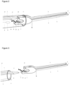
- the proximal portion of the device is secured by the distal end of a rigid control wire 13 positioned in a fragile connection 14 on a curved projection 15 which retains the end of the rigid wire 13 in the fragile connection 14 which fails upon further application of the predefined force of traction on the flexible control wire 9, which allows the loop 11 of the flexible control wire 9 to pass over the projection 15, which causes the distal end of the rigid wire 13 to separate from the fragile connection 14 [ Fig 2 ].
- Applying a pushing force to the control handle of the proximal end of the flexible element 1 causes the device to fully exit the distal end 2 of the flexible tubular element 1 [ Fig 3 ].
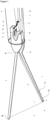
- the first 3 and second 4 arms of the device preferably have an angulation 16 [ Fig 1 ] predefined proximal end allowing the separation of the two ends of the first 3 and second 4 arms of the device once exited from the distal end of the flexible tubular element 1 such that in the open position of said device, the distal ends of the first 3 and second 4 arms are separated, allowing said device to be positioned on the target tissue area to be grasped.
- the distal end of the second arm 4 is connected by a flexible tightening wire 5 with a predefined length, said flexible tightening wire 5 of predefined resorbable or non-resorbable material.
- the invention relates in one aspect to a device for closing or ligating tissue at the internal wall of a hollow organ such as the digestive tract or other bodily lumens and hollow organs characterized in that it comprises an elongate and flexible tubular element 1, used through a working channel of an endoscope of which a proximal end remains external to the body, accessible to a user with a joystick while a distal end 2 of the flexible tubular element 1 is inserted into the hollow organ after its introduction into the working channel of the endoscope to a location adjacent to the target tissue to be closed or ligated, said device also comprising two control wires, a flexible control wire 9 and a rigid control wire 13 extending through the flexible tubular element 1, the two control wires 9, 13 being removably coupled to the device, the device comprising a first 3 and a second 4 arm each of a predefined length, the distal end of the second arm 4 being connected by a flexible clamping wire 5 with a predefined length, the other end of the flexible clamping
- the device is therefore preferably designed so that at least part of the flexible control wire 9 extends along the first arm 3, close to the latter and away from the second arm 4. This is notably permitted by the positioning of the slot (more precisely a through-light here) 8, at the level of the first distal end 19 of the first stocking 3, through which the first loop 7 of the tightening wire 5 passes.
- This makes it possible to have a free space, devoid of of wire (in particular flexible control wire 9, or flexible clamping wire 5), as seen in figure 1 , this free space being intended to accommodate the target tissue to be closed or ligated.
- the first loop 7 is therefore advantageously located only in the vicinity of the first distal end 19, because it has not been stretched and therefore has a reduced or minimal size ( figures 1 And 4 ), while in the closed configuration, the first loop 7 advantageously extends all along the first arm 3 up to the proximal part 18 (and more precisely up to the first projection 12), because it has been stretched (by the flexible control wire 9) and therefore has an enlarged or maximum size ( Figures 2 and 3 , and particularly visible at the figure 5 ).
- Said first arm 3 preferably comprising, as illustrated, an inner side or edge 21 facing said second arm 4 as well as an outer side or edge 6 opposite said inner side or edge 21 and therefore facing outwards.
- the first loop 7 therefore passes from the outer side or edge 6 to end up facing the inner side or edge 21, preferably between said first and second arms 3, 4, advantageously in the vicinity of the first distal end 19 of the first arm 3 (at least in the open configuration).
- the device comprises a substantially elongated and flexible tubular element 1, intended to be used through a working channel of an endoscope, a proximal end of which remains external to the body and accessible to a user, for example with a joystick, the tubular element 1 thus comprising a distal end 2 intended to be inserted into the hollow organ after its introduction into the working channel of the endoscope to a location adjacent to the target tissue to be closed or ligated, said flexible control wire 9 extending through said tubular element 1.
- the device preferably comprises a rigid control wire or rod 13 extending through said tubular element 1 to said proximal portion 18, said rigid control wire or rod 13 being adapted to move the proximal portion 18 within the tubular element 1, for example by applying a pushing or pulling force to said rigid control wire or rod 13, the pushing or pulling being preferably carried out relative to the proximal part 18 (pushed towards the proximal part 18, pulled away from it).
- the rigid control wire or rod 18 preferably has its own mechanical strength, and in particular is not flaccid. On the contrary, the flexible control wires 9 and clamping wires 5 are advantageously flaccid, without their own mechanical strength, as illustrated in the figures.
- the transition from the initial configuration to the open configuration is preferably done by applying a pushing force to the rigid control wire or rod 13 within the tubular element 1, said pushing force being transmitted by the rigid control wire or rod 13 to said proximal portion 18.
- the rigid control wire or rod 13 is provided with a fourth distal end 17 designed to interact with said proximal portion 18, and a third proximal end (not illustrated, but preferably located outside the hollow organ) allowing a user to manipulate the movement of said rigid control wire or rod 13 within the tubular element 1, and in particular to push said rigid control wire or rod 13.
- said fourth distal end 17 abuts against the proximal part 18, in particular in the initial configuration and/or in the open configuration.
- the device is advantageously designed so that the application of a pushing force at the third proximal end of the rigid control wire or rod 13 causes the second assembly to completely exit the tubular element 1, as illustrated in figure 3 (more precisely, between the figure 2 and 3 , there is the aforementioned thrust force that has been applied).
- the said second assembly advantageously remains at the location of the ligature or closure of the tissue, while the first assembly is removed from the hollow organ and more generally from the patient's body.
- said proximal portion 18 comprises an elastic return deformation means 16 for automatically positioning the first and second arms 3, 4 at a predefined angulation relative to each other.
- the first and second distal ends 19, 20 are therefore spaced apart from each other, as soon as said first and second arms 3, 4 are extended out of the tubular element. 1 and that the flexible clamping wire 5 is not tensioned or pulled by the flexible control wire 9, in particular in the open configuration, which makes it possible to position said first and second arms 3, 4 at the target tissue to be closed or ligated.
- the elastic return deformation means 16 makes it possible to automatically separate said first and second arms 3, 4, as long as they are not constrained and brought closer to each other by another force, for example exerted by the clamping wire 5 (closed configuration, Figures 2 and 3 ), or by an internal wall of the tubular element 1 (initial configuration, not illustrated here).
- said first loop 7 is positioned substantially between said first and second arms 3, 4.
- said first and second arms 3, 4 form a reclosable clamp, the opening of the clamp being carried out automatically, in the open configuration, using a return means, for example an elastic return deformation means 16, while the closing of the clamp is carried out, in the closed configuration, by the flexible clamping wire 5 which is held in tension to keep said first and second distal ends 19, 20 close to one another.
- a return means for example an elastic return deformation means 16
Landscapes
- Health & Medical Sciences (AREA)
- Surgery (AREA)
- Life Sciences & Earth Sciences (AREA)
- Heart & Thoracic Surgery (AREA)
- Nuclear Medicine, Radiotherapy & Molecular Imaging (AREA)
- Vascular Medicine (AREA)
- Engineering & Computer Science (AREA)
- Biomedical Technology (AREA)
- Reproductive Health (AREA)
- Medical Informatics (AREA)
- Molecular Biology (AREA)
- Animal Behavior & Ethology (AREA)
- General Health & Medical Sciences (AREA)
- Public Health (AREA)
- Veterinary Medicine (AREA)
- Surgical Instruments (AREA)
Description
Selon les modes de réalisation, la présente invention concerne un dispositif pour la fermeture ou la ligature de tissu au niveau de la paroi interne d'un organe creux comme le tube digestif ou d'autres lumières corporelles et organes creux qui est relativement simple à fabriquer et à utiliser.According to the embodiments of the present invention, a device for closing or ligating tissue at the inner wall of a hollow organ such as the digestive tract or other body lumens and hollow organs is provided which is relatively simple to manufacture and use.
Les exemples des dispositifs disponibles disposent d'outils de type: « Endoloop ® » ou « Polyloop ® », avec positionnement difficile en raison d'une souplesse trop importante de sa boucle et un système de serrage et de séparation complexe.Examples of available devices include tools of the type: " Endoloop ® " or " Polyloop ® ", with difficult positioning due to excessive flexibility of its loop and a complex tightening and separation system.
Le document
La présente invention vise donc à remédier à ces inconvénients : avoir un outil simple, qui s'utilise dans le canal de travail d'un endoscope.The present invention therefore aims to remedy these drawbacks: to have a simple tool, which is used in the working channel of an endoscope.
Ce dispositif possède deux bras rigides permettant son positionnement facilement autour de la lésion ou la zone de tissu cible avec une force de serrage prédéfinie permettant la fermeture ou la ligature du tissu cible de façon efficace et durable, il s'utilise par simple introduction dans le canal de travail de l'endoscope.This device has two rigid arms allowing its easy positioning around the lesion or target tissue area with a predefined clamping force allowing the closure or ligation of the target tissue in an effective and durable manner, it is used by simple introduction into the working channel of the endoscope.
Ce dispositif comprend un élément tubulaire 1 allongé, flexible, utilisé à travers un canal de travail d'un endoscope dont une extrémité proximale reste externe au corps, accessible à un utilisateur avec manette (poignée de contrôle) tandis qu'une extrémité distale 2 de l'élément flexible est insérée dans l'organe creux après son introduction dans le canal de travail de l'endoscope jusqu'à un emplacement adjacent au tissu cible à fermer ou à ligaturer. Ledit dispositif comprend aussi deux fils de commande, un fil 9 souple de commande et un fil 13 rigide de commande s'étendant à travers l'élément flexible 1, les deux fils étant couplés de manière amovible au dispositif. Ledit dispositif peut être en matière isolante non conductrice du courant électrique (type plastique), par exemple dans le cas de résection de tissu ligaturé avec un courant de section coagulation, ou en matière conductrice (du courant électrique), par exemple dans le cas de résection de tissu ligaturé à froid ou encore dans le cas d'utilisation du dispositif uniquement pour la fermeture du tissu.This device comprises an elongated, flexible
Ce dispositif comprend un premier 3 et un second 4 bras d'une longueur prédéfinie, l'extrémité distale du second bras 4 est reliée par un fil 5 souple de serrage avec une longueur prédéfinie, ledit fil 5 souple de serrage pouvant être en matière prédéfinie résorbable ou non résorbable. L'autre extrémité du fil 5 souple de serrage est fixée sur le bord externe 6 de l'extrémité distale du premier bras 3, une boucle 7 dudit fil 5 souple de serrage passe du coté externe dans la fente 8 de l'extrémité distale du premier bras 3.This device comprises a first 3 and a second 4 arm of a predefined length, the distal end of the
Le fil 9 souple passe dans une fente10 au niveau de la partie proximale du dispositif. Ledit fil 9 passe ensuite dans la boucle 7 du fil 5. Ledit fil 9 présente à son extrémité une boucle 11 de taille prédéfinie. La boucle 11 de l'extrémité du fil 9 souple est retenue sur une saillie 12 à l'extrémité proximale du dispositif.The
La partie proximale 18 du dispositif est fixée par l'extrémité 17 distale du fil 13 rigide de commande positionnée dans une liaison fragile 14. La saillie 15 de forme courbée retient l'extrémité 17 distale du fil 13 rigide de commande dans la liaison fragile qui échoue lorsque le dispositif est complètement sorti de l'extrémité distale 2 de l'élément flexible 1 pour séparer le dispositif de l'attache du fil 13 rigide de commande. Un actionneur à l'extrémité proximale de l'élément flexible 1 couplé au fil 13 rigide de commande et configuré pour déplacer le dispositif dans l'extrémité de l'élément flexible 1 jusqu'à la sortie du premier 3 et second 4 bras du dispositif permettant une position ouverte et son retrait dans l'extrémité distale de l'élément flexible 1 pour une configuration fermée. Le premier 3 et le second 4 bras du dispositif présentent une angulation 16 proximale prédéfinie permettant l'écartement des deux extrémités du premier 3 et du second 4 bras du dispositif une fois sorti de l'extrémité distale de l'élément flexible 1. Dans la configuration ouverte, les extrémités distales des premier 3 et second 4 bras du dispositif sont séparées, permettant de positionner le dispositif sur la zone de tissu cible à saisir. Dans une variante des modes de réalisation les premiers 3 et second 4 bras du dispositif contiennent des griffes en nombre prédéfini orientées face interne permettant l'accrochage du premier 3 et second 4 bras au tissu cible.The
Dans la configuration ouverte [
L'invention concerne selon un aspect un dispositif pour la fermeture ou la ligature de tissu au niveau de la paroi interne d'un organe creux comme le tube digestif ou d'autres lumières corporelles et organes creux caractérisés en ce qu'il comprend une partie proximale, (ladite partie proximale comprenant une fente 10 et une liaison fragile 14), un premier 3 et un second 4 bras d'une longueur prédéfinie, dont l'extrémité distale du second bras 4 est reliée par un fil 5 souple de serrage (de matière résorbable ou non résorbable) avec une longueur prédéfinie, un fil souple de commande 9 passant à travers ladite fente 10, Ledit fil 9 souple passe ensuite dans la boucle 7 du fil 5 souple de serrage (de matière résorbable ou non résorbable). Ledit fil 9 présente à son extrémité une boucle 11 de taille prédéfinie. La boucle 11 de l'extrémité du fil 9 souple est retenue sur une saillie 12 à l'extrémité proximale du dispositif, ladite saillie 12 permettant de retenir la boucle 7 et permettant la fixation du fil 5 souple de serrage en position de traction et un fil rigide de commande 13 positionné dans ladite liaison fragile 14. Le fil 13 rigide de commande est configuré pour déplacer le dispositif dans l'extrémité distale d'un élément tubulaire flexible 1 de telle sorte que les premier 3 et second 4 bras dudit dispositif puissent sortir de l'élément tubulaire flexible 1 permettant une position ouverte dudit dispositif et/ou que les premier 3 et second 4 bras dudit dispositif puissent être retirés dans l'extrémité distale de l'élément tubulaire flexible 1 permettant une position fermée dudit dispositif. La partie proximale du dispositif est fixée par l'extrémité distale d'un fil 13 rigide de commande positionnée dans une liaison fragile 14 sur une saillie 15 de forme courbée qui retient l'extrémité du fil 13 rigide dans la liaison 14 fragile qui échoue à la poursuite de l'application de la force prédéfinie de la traction sur le fil 9 souple de commande, qui permet le passage de la boucle 11 du fil 9 souple de commande sur la saillie 15, ce qui provoque la séparation de l'extrémité distale du fil 13 rigide de la liaison fragile 14 [
Les premier 3 et second 4 bras du dispositif présentent de préférence une angulation 16 [
En d'autres termes, l'invention concerne selon un aspect un dispositif pour la fermeture ou la ligature de tissu au niveau de la paroi interne d'un organe creux comme le tube digestif ou d'autres lumières corporelles et organes creux caractérisé en ce qu'il comprend un élément tubulaire 1 allongé et flexible, utilisé à travers un canal de travail d'un endoscope dont une extrémité proximale reste externe au corps, accessible à un utilisateur avec manette tandis qu'une extrémité distale 2 de l'élément tubulaire flexible 1 est insérée dans l'organe creux après son introduction dans le canal de travail de l'endoscope jusqu'à un emplacement adjacent au tissu cible à fermer ou à ligaturer, ledit dispositif comprenant aussi deux fils de commande, un fil 9 souple de commande et un fil rigide 13 de commande s'étendant à travers l'élément tubulaire flexible 1, les deux fils de commande 9, 13 étant couplés de manière amovible au dispositif, le dispositif comprenant un premier 3 et un second 4 bras chacun d'une longueur prédéfinie, l'extrémité distale du second bras 4 étant reliée par un fil souple de serrage 5 avec une longueur prédéfinie, l'autre extrémité du fil souple de serrage 5 étant fixée sur le bord externe 6 de l'extrémité distale du premier bras 3, une boucle 7 dudit fil souple de serrage 5 passant du coté externe dans une fente 8 de l'extrémité distale du premier bras 3, le fil souple de commande 9 passant dans une fente 10 au niveau de la partie proximale du dispositif, ledit fil souple de commande 9 passant ensuite dans la boucle 7 du fil souple de serrage 5, ledit fil souple de commande 9 présentant à son extrémité une boucle 11 de taille prédéfinie, la boucle 11 de l'extrémité du fil 9 souple étant retenue sur une saillie 12 à l'extrémité proximale du dispositif, la partie proximale 18 du dispositif étant fixée par l'extrémité distale 17 du fil rigide de commande 13 positionnée dans une liaison fragile 14, une saillie 15 de forme courbée retenant l'extrémité distale 17 du fil rigide de commande 13 dans la liaison fragile 14 qui échoue lorsque le dispositif est complètement sorti de l'extrémité distale 2 de l'élément tubulaire flexible 1 pour séparer le dispositif de l'attache du fil rigide de commande 13.In other words, the invention relates in one aspect to a device for closing or ligating tissue at the internal wall of a hollow organ such as the digestive tract or other bodily lumens and hollow organs characterized in that it comprises an elongate and flexible
En d'autres termes encore, l'invention concerne selon un aspect un dispositif pour la fermeture ou la ligature d'un tissu cible au niveau de la paroi interne d'un organe creux comme le tube digestif ou d'autres lumières corporelles et organes creux. Le dispositif comprend ainsi :
- une partie proximale pourvue d'une
première saillie 12 et d'unepremière fente 10, - un
premier bras 3 et unsecond bras 4 solidaires l'un de l'autre au niveau de ladite partie proximale 18, leditpremier bras 3 étant pourvu d'une première extrémité distale 19 et d'unedeuxième fente 8, leditsecond bras 3 étant pourvu d'une deuxième extrémité distale 20, - un fil souple de
serrage 5 reliant lesdits premier et secondbras serrage 5 formant unepremière boucle 7 passant, depuis un côté externe 6 dupremier bas 3, dans ladeuxième fente 8, - un fil souple de
commande 9 comprenant unedeuxième boucle 11.
- a proximal portion provided with a
first projection 12 and afirst slot 10, - a
first arm 3 and asecond arm 4 secured to each other at saidproximal part 18, saidfirst arm 3 being provided with a firstdistal end 19 and asecond slot 8, saidsecond arm 3 being provided with a seconddistal end 20, - a
flexible tightening wire 5 connecting said first andsecond arms distal ends wire 5 forming afirst loop 7 passing, from anexternal side 6 of thefirst stocking 3, into thesecond slot 8, - a
flexible control wire 9 comprising asecond loop 11.
Ledit dispositif est conçu pour passer :
- d'une configuration ouverte (
figure 1 ), où :- ∘ lesdits première et deuxième extrémités distales 19, 20 sont écartées l'un de l'autre,
- ∘ le fil souple de
commande 9 s'étend à travers laditepremière fente 10, vers lapremière boucle 7, passe dans cette dernière, puis revient vers ladite partie proximale 18 pour se fixer à laditepremière saillie 12 avec ladeuxième boucle 11,
- à une configuration fermée (
figures 2 et 3 ), après qu'une force de traction ait été exercée sur le fil souple decommande 9, où :- ∘ ledit fil souple de
commande 9 entraîne avec lui laditepremière boucle 7 jusqu'à laditepremière saillie 12, pour que cette dernière retienne laditepremière boucle 7, - ∘ ledit fil souple de
commande 9 se libère de laditepremière saillie 12, - ∘ lesdits première et deuxième extrémités distales 19, 20 sont rapprochées l'une de l'autre grâce au fil de
serrage 5, pour la fermeture ou la ligature du tissu cible.
- ∘ ledit fil souple de
- of an open configuration (
figure 1 ), Or :- ∘ said first and
second distal ends - ∘ the
flexible control wire 9 extends through saidfirst slot 10, towards thefirst loop 7, passes through the latter, then returns towards saidproximal part 18 to attach to saidfirst projection 12 with thesecond loop 11,
- ∘ said first and
- to a closed configuration (
Figures 2 and 3 ), after a tensile force has been exerted on theflexible control wire 9, where:- ∘ said
flexible control wire 9 carries with it saidfirst loop 7 to saidfirst projection 12, so that the latter retains saidfirst loop 7, - ∘ said
flexible control wire 9 is released from saidfirst projection 12, - ∘ said first and second
distal ends wire 5, for closing or ligating the target tissue.
- ∘ said
En configuration ouverte, le dispositif est donc préférentiellement conçu pour qu'une partie au moins du fil souple de commande 9 s'étende le long du premier bras 3, à proximité de ce dernier et à l'écart du second bras 4. Ceci est notamment permis par le positionnement de la fente (plus précisément une lumière traversante ici) 8, au niveau de la première extrémité distale 19 du premier bas 3, par laquelle passe la première boucle 7 du fil de serrage 5. Ceci permet d'avoir un espace libre, dépourvu de fil (notamment de fil souple de commande 9, ou de fil souple de serrage 5), comme on le voit à la
Ledit premier bras 3 comprenant de préférence, comme illustré, un côté ou bord interne 21 tourné vers ledit second bras 4 ainsi qu'un côté ou bord externe 6 à l'opposé dudit côté ou bord interne 21 et donc tourné vers l'extérieur. La première boucle 7 passe donc du côté ou bord externe 6 pour se retrouver face au côté ou bord interne 21, de préférence entre lesdits premier et second bras 3, 4, avantageusement au voisinage de la première extrémité distale 19 du premier bras 3 (au moins en configuration ouverte).Said
Selon un mode de réalisation avantageux et tel qu'illustré aux figures, le dispositif comprend un élément tubulaire 1 sensiblement allongé et flexible, destiné à être utilisé à travers un canal de travail d'un endoscope dont une extrémité proximale reste externe au corps et accessible à un utilisateur, par exemple avec une manette, l'élément tubulaire 1 comprenant ainsi une extrémité distale 2 destinée à être insérée dans l'organe creux après son introduction dans le canal de travail de l'endoscope jusqu'à un emplacement adjacent au tissu cible à fermer ou à ligaturer, ledit fil souple de commande 9 s'étendant à travers ledit élément tubulaire 1.According to an advantageous embodiment and as illustrated in the figures, the device comprises a substantially elongated and flexible
Le dispositif comprend de préférence un fil ou tige rigide de commande 13 s'étendant à travers ledit élément tubulaire 1 jusqu'à ladite partie proximale 18, ledit fil ou tige rigide de commande 13 étant conçu pour déplacer la partie proximale 18 au sein de l'élément tubulaire 1, par exemple par application d'une force de poussée ou de traction sur ledit fil ou tige rigide de commande 13, la poussée ou la traction étant de préférence réalisée relativement à la partie proximale 18 (poussée vers la partie proximale 18, traction à l'écart de celle-ci). Le fil ou tige rigide de commande 18 présente de préférence une tenue mécanique propre, et en particulier n'est pas flasque. Au contraire, les fils souples de commande 9 et de serrage 5 sont avantageusement flasques, sans tenue mécanique propre, comme illustré aux figures.The device preferably comprises a rigid control wire or
De manière préférentielle, le dispositif pour la fermeture ou la ligature d'un tissu cible est conçu pour passer :
- d'une configuration initiale (non illustrée), où :
- ∘ les premier et
second bras - ∘ lesdits première et deuxième extrémités distales 19, 20 sont rapprochées l'une de l'autre grâce à l'élément tubulaire 1 entourant lesdits premier et
second bras - ∘ les fils souples de serrage 5 et de commande 9 sont sensiblement comme dans la configuration ouverte,
- ∘ les premier et
- à la configuration ouverte, où de surcroît les premier et
second bras
- from an initial configuration (not shown), where:
- ∘ the first and
second arms tubular element 1, - ∘ said first and second distal ends 19, 20 are brought closer to each other by means of the
tubular element 1 surrounding said first andsecond arms - ∘ the
flexible clamping wires 5 andcontrol wires 9 are substantially as in the open configuration,
- ∘ the first and
- in the open configuration, where in addition the first and
second arms tubular element 1.
Le passage de la configuration initiale à la configuration ouverte se fait de préférence par l'application d'une force de poussée sur le fil ou tige rigide de commande 13 au sein de l'élément tubulaire 1, ladite force de poussée étant transmise par le fil ou tige rigide de commande 13 à ladite partie proximale 18.The transition from the initial configuration to the open configuration is preferably done by applying a pushing force to the rigid control wire or
De manière préférentielle, le fil ou tige rigide de commande 13 est pourvue d'une quatrième extrémité distale 17 conçue pour interagir avec ladite partie proximale 18, et d'une troisième extrémité proximale (non illustrée, mais de préférence située hors de l'organe creux) permettant à un utilisateur de manipuler le déplacement dudit fil ou tige rigide de commande 13 au sein de l'élément tubulaire 1, et notamment de pousser ledit fil ou tige rigide de commande 13.Preferably, the rigid control wire or
De préférence, comme illustré à la
Selon un mode de réalisation particulier, ledit fil ou tige rigide de commande 13 comprend, au niveau de ladite quatrième extrémité distale 17, un moyen de liaison fragile 14, et en ce que ladite partie proximale 18 est pourvue d'une deuxième saillie 15, de préférence distincte de ladite première saillie 12, ledit moyen de liaison fragile 14 et ladite deuxième saillie 15 étant conçus pour :
- en configuration initiale et/ou en configuration ouverte, être attachés ensemble, de préférence mécaniquement,
- en configuration fermée, être désolidarisés l'un de l'autre, de sorte que l'élément tubulaire 1, le fil souple de commande 9 et le fil ou tige rigide de commande 13 forment un premier ensemble (à gauche sur la
figure 3 ), ledit premier ensemble étant alors désolidarisé d'un second ensemble (à droite sur lafigure 3 ) comprenant au moins la partie proximale 18, les premier etsecond bras
- in the initial configuration and/or in the open configuration, be attached together, preferably mechanically,
- in closed configuration, be separated from each other, so that the
tubular element 1, theflexible control wire 9 and the rigid control wire orrod 13 form a first assembly (on the left in thefigure 3 ), said first set then being separated from a second set (on the right on thefigure 3 ) comprising at least theproximal part 18, the first andsecond arms flexible tightening wire 15.
Le dispositif est conçu avantageusement pour que l'application d'une force de poussée au niveau de la troisième extrémité proximale du fil ou tige rigide de commande 13 entraîne la sortie complète du second ensemble hors de l'élément tubulaire 1, comme illustré à la
Ledit second ensemble reste avantageusement à l'endroit de la ligature ou de la fermeture du tissu, tandis que le premier ensemble est retiré hors de l'organe creux et plus généralement hors du corps du patient.The said second assembly advantageously remains at the location of the ligature or closure of the tissue, while the first assembly is removed from the hollow organ and more generally from the patient's body.
De manière avantageuse, ladite partie proximale 18 comprend un moyen de déformation élastique de rappel 16 permettant de positionner automatiquement les premier et second bras 3, 4 à une angulation prédéfinie l'un relativement à l'autre. Les première et deuxième extrémités distales 19, 20 sont donc éloignées l'une de l'autre, dès lors que lesdits premier et second bras 3, 4 sont sortis hors de l'élément tubulaire 1 et que le fil souple de serrage 5 n'est pas tendu ou tiré par le fil souple de commande 9, en particulier en configuration ouverte, ce qui permet de positionner lesdits premier et second bras 3, 4 au niveau du tissu cible à fermer ou à ligaturer. En d'autres termes, le moyen de déformation élastique de rappel 16 permet d'écarter automatiquement lesdits premier et second bras 3, 4, dès lors qu'ils ne sont pas contraints et rapprochés l'un de l'autre par une autre force, par exemple exercée par le fil de serrage 5 (configuration fermée,
De manière préférentielle, comme illustré aux
En résumé, de manière particulièrement avantageuse, lesdits premier et second bras 3, 4 forment une pince refermable, l'ouverture de la pince étant réalisée automatiquement, en configuration ouverte, à l'aide d'un moyen de rappel, par exemple un moyen de déformation élastique de rappel 16, tandis que la fermeture de la pince est réalisée, en configuration fermée, par le fil souple de serrage 5 qui est maintenu en tension pour conserver lesdites première et deuxième extrémités distales 19, 20 à proximité l'une de l'autre.In summary, in a particularly advantageous manner, said first and
-
La
figure 1 est une vue du dispositif monobloc selon un mode de réalisation de la présente invention, en configuration ouverte.Therefigure 1 is a view of the monobloc device according to an embodiment of the present invention, in open configuration. -
La
figure 2 est une vue en perspective du dispositif monobloc après séparation du dispositif selon un mode de réalisation de la présente invention, en configuration fermée, avec la partie proximale 18 encore en partie dans l'élément tubulaire 1.Therefigure 2 is a perspective view of the one-piece device after separation of the device according to an embodiment of the present invention, in closed configuration, with theproximal portion 18 still partly in thetubular element 1. -
La
figure 3 est une vue en perspective du dispositif monobloc après séparation du dispositif de l'élément tubulaire 1 selon un mode de réalisation de la présente invention, et donc en configuration fermée, la partie proximale 18 étant donc complètement sortie de l'élément tubulaire flexible 1.Therefigure 3 is a perspective view of the single-piece device after separation of the device from thetubular element 1 according to an embodiment of the present invention, and therefore in closed configuration, theproximal part 18 therefore being completely removed from the flexibletubular element 1. -
La
figure 4 est une vue rapprochée de la première extrémité distale 19 du premier bras 3, en configuration ouverte (et éventuellement en configuration initiale).Therefigure 4 is a close-up view of the firstdistal end 19 of thefirst arm 3, in the open configuration (and possibly in the initial configuration). -
La
figure 5 est une vue rapprochée des première et deuxième extrémités distales 19, 20 appartenant respectivement au premier bras 3 et au second bras 4, en configuration fermée.Therefigure 5 is a close-up view of the first and second distal ends 19, 20 belonging respectively to thefirst arm 3 and to thesecond arm 4, in closed configuration.
- (1) Élément tubulaire flexible ;(1) Flexible tubular element;
-
(2) Extrémité distale de l'élément tubulaire flexible 1, dite troisième extrémité distale ;(2) Distal end of the flexible
tubular element 1, called the third distal end; - (3) Premier bras ;(3) First arm;
- (4) Deuxième (Second) bras ;(4) Second arm;
- (5) Fil souple de serrage ;(5) Flexible clamping wire;
-
(6) Bord externe du premier bras 3, au niveau de la première extrémité distale 19 du premier bras (3) ;(6) Outer edge of the
first arm 3, at the level of the firstdistal end 19 of the first arm (3); -
(7) Première boucle du fil souple de serrage 5 ;(7) First loop of the
flexible tightening wire 5; -
(8) Fente (ou lumière traversante) de la première extrémité distale 9 du premier bras 3 ;(8) Slot (or through light) of the first
distal end 9 of thefirst arm 3; - (9) Fil souple de commande ;(9) Flexible control wire;
-
(10) fente (ou lumière traversante) au niveau de la partie proximale 18 du dispositif ;(10) slit (or through-light) at the
proximal portion 18 of the device; -
(11) Deuxième boucle de l'extrémité distale 9 du fil souple de commande 9 ;(11) Second loop of the
distal end 9 of theflexible control wire 9; - (12) Première saillie, au niveau de l'extrémité (ou partie) proximale 18 du dispositif ;(12) First projection, at the proximal end (or part) 18 of the device;
- (13) Fil (ou tige) rigide de commande ;(13) Rigid control wire (or rod);
- (14) Liaison fragile ou moyen de liaison fragile, en l'occurrence ici une encoche ;(14) Fragile connection or fragile means of connection, in this case a notch;
- (15) Deuxième saillie, de préférence de forme courbée ;(15) Second projection, preferably curved in shape;
-
(16) Angulation proximale prédéfinie, ou moyen de déformation élastique de rappel de la partie proximale 18, permettant l'écartement (de préférence prédéfini), en configuration ouverte, des première et deuxième extrémités distales 19, 20 respectivement du premier 3 et du second 4 bras ;(16) Predefined proximal angulation, or elastic deformation means for returning the
proximal part 18, allowing the separation (preferably predefined), in open configuration, of the first and second distal ends 19, 20 respectively of the first 3 and second 4 arms; -
(17) Extrémité distale du fil rigide de commande 13, dite quatrième extrémité distale ;(17) Distal end of the
rigid control wire 13, called the fourth distal end; - (18) Partie (ou extrémité) proximale du dispositif ;(18) Proximal part (or end) of the device;
-
(19) Première extrémité distale du premier bras 3 ;(19) First distal end of the
first arm 3; -
(20) Deuxième extrémité distale du second bras 4 ;(20) Second distal end of the
second arm 4; -
(21) côté ou bord interne du premier bras 3.(21) side or inner edge of the
first arm 3.
Claims (11)
- Device for closing or ligating a target tissue at the inner wall of a hollow organ, such as the digestive tract or other body lumens and hollow organs, characterized in that it comprises:• a proximal part provided with a first protrusion (12) and a first slot (10),• a first arm (3) and a second arm (4) fixed to each other at said proximal part (18), said first arm (3) being provided with a first distal end (19) and a second slot (8), said second arm (4) being provided with a second distal end (20),• a flexible tightening thread (5) connecting said first and second arms (3, 4) at their respective first and second distal ends (19, 20), said flexible tightening thread (5) forming a first loop (7) passing from an outer side (6) of the first arm (3) into the second slot (8),• a flexible control thread (9) comprising a second loop (11), wherein said device is designed to move:• from an open configuration, wherein:• said first and second distal ends (19, 20) are spaced apart from each other,• the control thread (9) extends through said first slot (10) toward the first loop (7), passes through it, and then returns to said proximal part (18) to be fixed to said first protrusion (12) with the second loop (11),• to a closed configuration, after a pulling force has been exerted on the control thread (9), wherein:• the control thread (9) pulls along said first loop (7) up to said first protrusion (12), so that the latter retains said first loop (7),• the control thread (9) releases from said first protrusion (12),• said first and second distal ends (19, 20) are drawn toward each other by the tightening thread (5), for closing or ligating the target tissue.
- Device for closing or ligating a target tissue according to the preceding claim, characterized in that it comprises a substantially elongated and flexible tubular element (1) intended to be used through a working channel of an endoscope, one proximal end of which remains external to the body and accessible to a user, for example with a lever, the tubular element (1) thus comprising a third distal end (2) intended to be inserted into the hollow organ after its introduction into the endoscope's working channel to a location adjacent to the target tissue to be closed or ligated, said control thread (9) extending through said tubular element (1).
- Device for closing or ligating a target tissue according to the preceding claim, characterized in that it comprises a rigid control wire or rod (13) extending through said tubular element (1) to said proximal part (18), said rigid control wire or rod (13) being designed to move the proximal part (18) within the tubular element (1).
- Device for closing or ligating a target tissue according to the preceding claim, characterized in that it is designed to transition:• from an initial configuration, wherein:• the first and second arms (3, 4) are positioned within the tubular element (1),• said first and second distal ends (19, 20) are close to each other by the surrounding tubular element (1),• the flexible tightening and control threads (5, 9) are in substantially the same configuration as in the open configuration,• to the open configuration, wherein the first and second arms (3, 4) are positioned outside the tubular element (1), the transition from the initial to the open configuration being achieved by:• applying a pushing force on the rigid control wire or rod (13) within the tubular element (1), said pushing force being transmitted by the rigid control wire or rod (13) to said proximal part (18).
- Device for closing or ligating a target tissue according to claims 3 or 4, characterized in that the rigid control wire or rod (13) is provided with a fourth distal end (17) designed to interact with said proximal part (18), and a third proximal end allowing a user to manipulate the movement of said rigid control wire or rod (13) within the tubular element (1), specifically to push said rigid control wire or rod (13).
- Device for closing or ligating a target tissue according to the preceding claim, characterized in that said fourth distal end (17) abuts against the proximal part (18), particularly in the initial and/or open configuration.
- Device for closing or ligating a target tissue according to claims 5 or 6, characterized in that said rigid control wire or rod (13) comprises, at said fourth distal end (17), a fragile connecting means (14), and in that said proximal part (18) is provided with a second protrusion (15), preferably separate from said first protrusion (12), said fragile connecting means (14) and said second protrusion (15) being designed to:• in the initial and/or open configuration, be attached together, preferably mechanically,• in the closed configuration, be detached from each other, so that the tubular element (1), the control thread (9), and the rigid control wire or rod (13) form a first assembly, said first assembly being then detached from a second assembly comprising at least the proximal part (18), the first and second arms (3, 4), and the tightening thread (5).
- Device for closing or ligating a target tissue according to the preceding claim, characterized in that it is designed such that applying a pushing force on the third proximal end of the rigid control wire or rod (13) causes the complete ejection of the second assembly from the tubular element (1).
- Device according to any one of claims 2 to 8, characterized in that said proximal part (18) includes an elastic return deformation means (16) for automatically positioning the first and second arms (3, 4) at a predefined angle relative to each other, the first and second distal ends (19, 20) thus being spaced apart, once the first and second arms (3, 4) are outside the tubular element (1) and the tightening thread (5) is neither taut nor pulled by the control thread (9), particularly in the open configuration, allowing positioning of the first and second arms (3, 4) at the target tissue to be closed or ligated.
- Device according to any one of the preceding claims, characterized in that said first loop (7) is positioned substantially between said first and second arms (3, 4).
- Device according to any one of the preceding claims, characterized in that the first and second arms (3, 4) form a closable clamp, the clamp opening being achieved automatically in the open configuration using a return means, for example an elastic return deformation means (16), while the clamp closure is achieved in the closed configuration by the tightening thread (5) which is held in tension to keep said first and second distal ends (19, 20) close to each other.
Applications Claiming Priority (1)
| Application Number | Priority Date | Filing Date | Title |
|---|---|---|---|
| FR2208854A FR3139271B1 (en) | 2022-09-03 | 2022-09-03 | Device for tissue ligation. |
Publications (2)
| Publication Number | Publication Date |
|---|---|
| EP4331506A1 EP4331506A1 (en) | 2024-03-06 |
| EP4331506B1 true EP4331506B1 (en) | 2025-01-22 |
Family
ID=86468762
Family Applications (1)
| Application Number | Title | Priority Date | Filing Date |
|---|---|---|---|
| EP23194927.2A Active EP4331506B1 (en) | 2022-09-03 | 2023-09-01 | Device for ligating tissue |
Country Status (2)
| Country | Link |
|---|---|
| EP (1) | EP4331506B1 (en) |
| FR (1) | FR3139271B1 (en) |
Family Cites Families (3)
| Publication number | Priority date | Publication date | Assignee | Title |
|---|---|---|---|---|
| US8764774B2 (en) * | 2010-11-09 | 2014-07-01 | Cook Medical Technologies Llc | Clip system having tether segments for closure |
| CA3070720A1 (en) * | 2017-10-11 | 2019-04-18 | Boston Scientific Scimed, Inc. | Reinforced mechanical hemostasis clip |
| FR3117327B1 (en) * | 2020-12-13 | 2022-10-28 | Abdelkrim Kada | Device for hemostasis or tissue closure. |
-
2022
- 2022-09-03 FR FR2208854A patent/FR3139271B1/en active Active
-
2023
- 2023-09-01 EP EP23194927.2A patent/EP4331506B1/en active Active
Also Published As
| Publication number | Publication date |
|---|---|
| FR3139271A1 (en) | 2024-03-08 |
| FR3139271B1 (en) | 2024-07-26 |
| EP4331506A1 (en) | 2024-03-06 |
Similar Documents
| Publication | Publication Date | Title |
|---|---|---|
| JP7794869B2 (en) | Endoscopic suturing system with external instrument channel - Patent Application 20070122997 | |
| EP2327364B1 (en) | Ligation apparatus | |
| EP2345377B1 (en) | Device for ligating an anatomical structure | |
| EP1882451B1 (en) | Clip apparatus for ligaturing living tissue | |
| EP0369324B1 (en) | Surgical instrument | |
| JP2022539372A (en) | Clamping device and its clamping part | |
| FR2640131A1 (en) | LIGATURE ASSEMBLY FOR ENDOSCOPIC SURGERY, LIGATURE AND LIGATURE HANDLING INSTRUMENT THEREFOR | |
| US8603111B2 (en) | Ligating apparatus | |
| EP3905970B1 (en) | Hemostasis clip short system | |
| EP4331506B1 (en) | Device for ligating tissue | |
| JPH05212043A (en) | Clipping device | |
| US20030216752A1 (en) | Device for laparoscopic tubal ligation | |
| WO2022072041A1 (en) | Repositionable closure device | |
| FR2698778A1 (en) | Two-part speculum for inspection of human or animal body cavity - comprises hollow guide tube with longitudinal slot, including conical inner portion receiving spacer tube to cause radial expansion | |
| US20110270234A1 (en) | Endoscopic surgical instrument | |
| FR3117327A1 (en) | Device for hemostasis or tissue closure. | |
| FR2831791A1 (en) | Device for introduction of snare in endoscopic surgery comprises applicator with axial guide constituted by rigid cartridge containing part of snare whose end overhangs outwards to be gripped by clamp | |
| JP2005224392A (en) | Endoscopic grasping forceps | |
| WO2003103503A1 (en) | Endoscopic biopsy forceps with protected cutting instrument |
Legal Events
| Date | Code | Title | Description |
|---|---|---|---|
| PUAI | Public reference made under article 153(3) epc to a published international application that has entered the european phase |
Free format text: ORIGINAL CODE: 0009012 |
|
| STAA | Information on the status of an ep patent application or granted ep patent |
Free format text: STATUS: THE APPLICATION HAS BEEN PUBLISHED |
|
| AK | Designated contracting states |
Kind code of ref document: A1 Designated state(s): AL AT BE BG CH CY CZ DE DK EE ES FI FR GB GR HR HU IE IS IT LI LT LU LV MC ME MK MT NL NO PL PT RO RS SE SI SK SM TR |
|
| STAA | Information on the status of an ep patent application or granted ep patent |
Free format text: STATUS: REQUEST FOR EXAMINATION WAS MADE |
|
| 17P | Request for examination filed |
Effective date: 20240719 |
|
| RBV | Designated contracting states (corrected) |
Designated state(s): AL AT BE BG CH CY CZ DE DK EE ES FI FR GB GR HR HU IE IS IT LI LT LU LV MC ME MK MT NL NO PL PT RO RS SE SI SK SM TR |
|
| GRAP | Despatch of communication of intention to grant a patent |
Free format text: ORIGINAL CODE: EPIDOSNIGR1 |
|
| STAA | Information on the status of an ep patent application or granted ep patent |
Free format text: STATUS: GRANT OF PATENT IS INTENDED |
|
| GRAS | Grant fee paid |
Free format text: ORIGINAL CODE: EPIDOSNIGR3 |
|
| RIC1 | Information provided on ipc code assigned before grant |
Ipc: A61B 90/00 20160101ALN20240906BHEP Ipc: A61B 17/00 20060101ALN20240906BHEP Ipc: A61B 17/128 20060101ALI20240906BHEP Ipc: A61B 17/122 20060101AFI20240906BHEP |
|
| INTG | Intention to grant announced |
Effective date: 20240920 |
|
| GRAA | (expected) grant |
Free format text: ORIGINAL CODE: 0009210 |
|
| STAA | Information on the status of an ep patent application or granted ep patent |
Free format text: STATUS: THE PATENT HAS BEEN GRANTED |
|
| AK | Designated contracting states |
Kind code of ref document: B1 Designated state(s): AL AT BE BG CH CY CZ DE DK EE ES FI FR GB GR HR HU IE IS IT LI LT LU LV MC ME MK MT NL NO PL PT RO RS SE SI SK SM TR |
|
| REG | Reference to a national code |
Ref country code: GB Ref legal event code: FG4D Free format text: NOT ENGLISH |
|
| REG | Reference to a national code |
Ref country code: CH Ref legal event code: EP |
|
| REG | Reference to a national code |
Ref country code: IE Ref legal event code: FG4D Free format text: LANGUAGE OF EP DOCUMENT: FRENCH |
|
| REG | Reference to a national code |
Ref country code: DE Ref legal event code: R096 Ref document number: 602023001761 Country of ref document: DE |
|
| REG | Reference to a national code |
Ref country code: NL Ref legal event code: MP Effective date: 20250122 |
|
| PG25 | Lapsed in a contracting state [announced via postgrant information from national office to epo] |
Ref country code: NL Free format text: LAPSE BECAUSE OF FAILURE TO SUBMIT A TRANSLATION OF THE DESCRIPTION OR TO PAY THE FEE WITHIN THE PRESCRIBED TIME-LIMIT Effective date: 20250122 |
|
| PG25 | Lapsed in a contracting state [announced via postgrant information from national office to epo] |
Ref country code: RS Free format text: LAPSE BECAUSE OF FAILURE TO SUBMIT A TRANSLATION OF THE DESCRIPTION OR TO PAY THE FEE WITHIN THE PRESCRIBED TIME-LIMIT Effective date: 20250422 |
|
| PG25 | Lapsed in a contracting state [announced via postgrant information from national office to epo] |
Ref country code: FI Free format text: LAPSE BECAUSE OF FAILURE TO SUBMIT A TRANSLATION OF THE DESCRIPTION OR TO PAY THE FEE WITHIN THE PRESCRIBED TIME-LIMIT Effective date: 20250122 |
|
| PG25 | Lapsed in a contracting state [announced via postgrant information from national office to epo] |
Ref country code: PL Free format text: LAPSE BECAUSE OF FAILURE TO SUBMIT A TRANSLATION OF THE DESCRIPTION OR TO PAY THE FEE WITHIN THE PRESCRIBED TIME-LIMIT Effective date: 20250122 |
|
| PG25 | Lapsed in a contracting state [announced via postgrant information from national office to epo] |
Ref country code: ES Free format text: LAPSE BECAUSE OF FAILURE TO SUBMIT A TRANSLATION OF THE DESCRIPTION OR TO PAY THE FEE WITHIN THE PRESCRIBED TIME-LIMIT Effective date: 20250122 |
|
| REG | Reference to a national code |
Ref country code: LT Ref legal event code: MG9D |
|
| PG25 | Lapsed in a contracting state [announced via postgrant information from national office to epo] |
Ref country code: NO Free format text: LAPSE BECAUSE OF FAILURE TO SUBMIT A TRANSLATION OF THE DESCRIPTION OR TO PAY THE FEE WITHIN THE PRESCRIBED TIME-LIMIT Effective date: 20250422 Ref country code: IS Free format text: LAPSE BECAUSE OF FAILURE TO SUBMIT A TRANSLATION OF THE DESCRIPTION OR TO PAY THE FEE WITHIN THE PRESCRIBED TIME-LIMIT Effective date: 20250522 |
|
| REG | Reference to a national code |
Ref country code: AT Ref legal event code: MK05 Ref document number: 1760850 Country of ref document: AT Kind code of ref document: T Effective date: 20250122 |
|
| PG25 | Lapsed in a contracting state [announced via postgrant information from national office to epo] |
Ref country code: HR Free format text: LAPSE BECAUSE OF FAILURE TO SUBMIT A TRANSLATION OF THE DESCRIPTION OR TO PAY THE FEE WITHIN THE PRESCRIBED TIME-LIMIT Effective date: 20250122 |
|
| PG25 | Lapsed in a contracting state [announced via postgrant information from national office to epo] |
Ref country code: LV Free format text: LAPSE BECAUSE OF FAILURE TO SUBMIT A TRANSLATION OF THE DESCRIPTION OR TO PAY THE FEE WITHIN THE PRESCRIBED TIME-LIMIT Effective date: 20250122 Ref country code: PT Free format text: LAPSE BECAUSE OF FAILURE TO SUBMIT A TRANSLATION OF THE DESCRIPTION OR TO PAY THE FEE WITHIN THE PRESCRIBED TIME-LIMIT Effective date: 20250522 |
|
| PG25 | Lapsed in a contracting state [announced via postgrant information from national office to epo] |
Ref country code: BG Free format text: LAPSE BECAUSE OF FAILURE TO SUBMIT A TRANSLATION OF THE DESCRIPTION OR TO PAY THE FEE WITHIN THE PRESCRIBED TIME-LIMIT Effective date: 20250122 Ref country code: GR Free format text: LAPSE BECAUSE OF FAILURE TO SUBMIT A TRANSLATION OF THE DESCRIPTION OR TO PAY THE FEE WITHIN THE PRESCRIBED TIME-LIMIT Effective date: 20250423 |
|
| PG25 | Lapsed in a contracting state [announced via postgrant information from national office to epo] |
Ref country code: AT Free format text: LAPSE BECAUSE OF FAILURE TO SUBMIT A TRANSLATION OF THE DESCRIPTION OR TO PAY THE FEE WITHIN THE PRESCRIBED TIME-LIMIT Effective date: 20250122 |
|
| PG25 | Lapsed in a contracting state [announced via postgrant information from national office to epo] |
Ref country code: SE Free format text: LAPSE BECAUSE OF FAILURE TO SUBMIT A TRANSLATION OF THE DESCRIPTION OR TO PAY THE FEE WITHIN THE PRESCRIBED TIME-LIMIT Effective date: 20250122 |
|
| PG25 | Lapsed in a contracting state [announced via postgrant information from national office to epo] |
Ref country code: SM Free format text: LAPSE BECAUSE OF FAILURE TO SUBMIT A TRANSLATION OF THE DESCRIPTION OR TO PAY THE FEE WITHIN THE PRESCRIBED TIME-LIMIT Effective date: 20250122 |
|
| PG25 | Lapsed in a contracting state [announced via postgrant information from national office to epo] |
Ref country code: DK Free format text: LAPSE BECAUSE OF FAILURE TO SUBMIT A TRANSLATION OF THE DESCRIPTION OR TO PAY THE FEE WITHIN THE PRESCRIBED TIME-LIMIT Effective date: 20250122 |
|
| PGFP | Annual fee paid to national office [announced via postgrant information from national office to epo] |
Ref country code: DE Payment date: 20250602 Year of fee payment: 5 |
|
| PG25 | Lapsed in a contracting state [announced via postgrant information from national office to epo] |
Ref country code: IT Free format text: LAPSE BECAUSE OF FAILURE TO SUBMIT A TRANSLATION OF THE DESCRIPTION OR TO PAY THE FEE WITHIN THE PRESCRIBED TIME-LIMIT Effective date: 20250122 |
|
| PG25 | Lapsed in a contracting state [announced via postgrant information from national office to epo] |
Ref country code: EE Free format text: LAPSE BECAUSE OF FAILURE TO SUBMIT A TRANSLATION OF THE DESCRIPTION OR TO PAY THE FEE WITHIN THE PRESCRIBED TIME-LIMIT Effective date: 20250122 Ref country code: CZ Free format text: LAPSE BECAUSE OF FAILURE TO SUBMIT A TRANSLATION OF THE DESCRIPTION OR TO PAY THE FEE WITHIN THE PRESCRIBED TIME-LIMIT Effective date: 20250122 |
|
| REG | Reference to a national code |
Ref country code: DE Ref legal event code: R097 Ref document number: 602023001761 Country of ref document: DE |
|
| PG25 | Lapsed in a contracting state [announced via postgrant information from national office to epo] |
Ref country code: RO Free format text: LAPSE BECAUSE OF FAILURE TO SUBMIT A TRANSLATION OF THE DESCRIPTION OR TO PAY THE FEE WITHIN THE PRESCRIBED TIME-LIMIT Effective date: 20250122 |
|
| PG25 | Lapsed in a contracting state [announced via postgrant information from national office to epo] |
Ref country code: SK Free format text: LAPSE BECAUSE OF FAILURE TO SUBMIT A TRANSLATION OF THE DESCRIPTION OR TO PAY THE FEE WITHIN THE PRESCRIBED TIME-LIMIT Effective date: 20250122 |
|
| PLBE | No opposition filed within time limit |
Free format text: ORIGINAL CODE: 0009261 |
|
| STAA | Information on the status of an ep patent application or granted ep patent |
Free format text: STATUS: NO OPPOSITION FILED WITHIN TIME LIMIT |
|
| 26N | No opposition filed |
Effective date: 20251023 |
|
| PGFP | Annual fee paid to national office [announced via postgrant information from national office to epo] |
Ref country code: IE Payment date: 20251130 Year of fee payment: 3 |