EP4330801B1 - Berührungsbildschirme mit akustischem modus und wählbaren eigenschaften - Google Patents
Berührungsbildschirme mit akustischem modus und wählbaren eigenschaften Download PDFInfo
- Publication number
- EP4330801B1 EP4330801B1 EP22720209.0A EP22720209A EP4330801B1 EP 4330801 B1 EP4330801 B1 EP 4330801B1 EP 22720209 A EP22720209 A EP 22720209A EP 4330801 B1 EP4330801 B1 EP 4330801B1
- Authority
- EP
- European Patent Office
- Prior art keywords
- wave
- transducers
- centerline
- shear
- mode
- Prior art date
- Legal status (The legal status is an assumption and is not a legal conclusion. Google has not performed a legal analysis and makes no representation as to the accuracy of the status listed.)
- Active
Links
Images







Classifications
-
- G—PHYSICS
- G06—COMPUTING OR CALCULATING; COUNTING
- G06F—ELECTRIC DIGITAL DATA PROCESSING
- G06F3/00—Input arrangements for transferring data to be processed into a form capable of being handled by the computer; Output arrangements for transferring data from processing unit to output unit, e.g. interface arrangements
- G06F3/01—Input arrangements or combined input and output arrangements for interaction between user and computer
- G06F3/03—Arrangements for converting the position or the displacement of a member into a coded form
- G06F3/041—Digitisers, e.g. for touch screens or touch pads, characterised by the transducing means
- G06F3/043—Digitisers, e.g. for touch screens or touch pads, characterised by the transducing means using propagating acoustic waves
- G06F3/0436—Digitisers, e.g. for touch screens or touch pads, characterised by the transducing means using propagating acoustic waves in which generating transducers and detecting transducers are attached to a single acoustic waves transmission substrate
Definitions
- touch sensors have found wide usage in for example, cell phones, touch pads, and automobiles. Most of these applications use what is known as projected capacitance touch panels because of their touch sensitivity, light weight, multi touch capability and ease of integration to a display. Projected capacitance touch sensors also have drawbacks. They are sensitive to liquids on the touch surface and they do not operate well with gloves. In addition they have sun light readability issues and can create electromagnetic interference. Further, these panels do not scale well to larger displays.
- Bezel free displays considered highly desirable for an increasing number of applications present difficulties for SAW and the Hecht et al.
- SAW to Lamb sensors because the four SAW generating or receiving elements may interfere with convenient mounting to a display.
- Laminating the touch panel to a display may be a desirable option as it increases impact resistance and improves display readability.
- this is difficult with Lamb modes with dominant out of plane wave motion as in the Hecht patent because the lamination adhesive absorbs Lamb wave energy and can cause excessive wave attenuation.
- the panel disclosed in the Knowles '327 patent has some attractive features. For example, it is not sensitive to water, needs only one array per coordinate, the transducers are directly coupled to the edge of the panel and it can be laminated with minimal acoustic attenuation.
- the one array per coordinate feature can be used to advantage to create acoustic sensors with redundancy for higher reliability with multiple characteristics.
- EP 2343693 discloses a touch sensor comprising an acoustic wave transmissive medium having a surface with a touch sensitive portion, a transducer system for emitting acoustic energy into said medium and a receiver system for receiving acoustic energy from the substrate.
- the receiver system is for receiving the acoustic energy as at least as two distinct sets of waves, a portion of each of which will overlap physically by propagating in said touch sensitive portion along axes which are non-orthogonal, said receiver system being for determining a position or a waveform perturbing characteristic of a touch on said touch sensitive portion.
- said at least two distinct sets of waves from said touch sensitive surface propagate along different sensing axes.
- US Publication 2013/234994 discloses an acoustic touch apparatus that has a variable thickness glass substrate that permits the transfer of surface acoustic waves between the back and front surfaces, thus enabling transducers to be placed on the substrate surface opposite the desired touch input surface.
- US 6091406 discloses an acoustic touch sensing device, comprising a substrate, having a surface and an acoustic wave transducer, transducing a bulk wave in the substrate propagating through the substrate along an axis intersecting the surface, wherein energy of the bulk wave is coupled to a wave having a converted wave mode with appreciable energy at the surface and propagating along the surface.
- the device may include a set of scattering centers to couple the bulk wave to a Rayleigh wave or plate wave.
- the Rayleigh wave or plate wave may be dispersed over a region of the substrate, and analyzed to detect a perturbation indicative of a position of touch.
- EP 1580651 discloses an acoustic wave type contact detector that includes two groups of inclined lines which are included in a spurious wave scattering means, that are formed at opposite angles with respect to each other in the vicinity of an upper edge of a substrate.
- the angles of the inclined lines are such that they are close to perpendicular toward the central portion of the substrate, and gradually decrease toward the edges thereof.
- two other groups inclined lines which are also included in the spurious wave scattering means are formed at opposite angles with respect to each other, with gradually changing angles.
- the spurious waves that reach these regions are diffused by the inclined lines so that they are not propagated to converters (sensors).
- Three rectangular spurious wave scattering means formed by inclined lines, inclined at angles other than 45°, also function to diffuse and eliminate spurious waves that propagate along the front surface of the substrate.
- a sensor as touch sensitive as the projected capacitance type but with low EMI and optical reflectivity.
- a sensor can be fabricated as thin or as thick as desired, is sensitive to gloved touch, insensitive to water, and straight forward to integrate to a display, including lamination to a display surface.
- Performance is further enhanced by a method of confining source modes to the arrays in the presence of wave diffraction through the use of collimation grooves and by the deployment where advantageous of non-Newtonian coatings which preferentially absorb undesired wave motion.
- a touch panel in an aspect, includes a substrate having first and second surfaces and edges extending between the first and second surfaces defining a thickness.
- a first plurality of echelons is arranged on the first surface of the substrate in a first array along a first centerline. Each echelon in the first plurality of echelons is formed at a first angle relative to the first centerline.
- a second plurality of echelons is arranged on the first surface of the substrate in a second array along a second centerline.
- Each echelon in the second plurality of echelons is formed at a second angle relative to the second centerline.
- the second centerline is orthogonal to the first centerline.
- a second shear transducer is mounted on the edge of the substrate and generates a shear wave in a source wave mode in a second direction along the second centerline.
- the shear wave generated by the first shear wave transducer propagates along the first centerline and is reflected at the first angle by the one or more of the plurality of echelons in the first array to a first sensing wave or the shear wave is converted to a different wave mode than the source mode.
- the first sensing wave is reflected off of an edge opposing the first centerline and is sensed by the first transducer.
- the shear wave generated by the second shear wave transducer propagates along the second centerline and is reflected at the second angle by the one or more of the plurality of echelons in the second array to a second sensing wave or the shear wave is converted to a different wave mode than the source mode.
- the second sensing wave is reflected off of an edge opposing the second centerline and is sensed by the second transducer.
- the first transducer is a pair of first transducers and the second transducer is a pair of second transducers.
- the first pair of transducers is mounted along the edge and the second pair of transducers is mounted along the edge.
- the transducers of the first pair of transducers can be oriented to generate stresses in a same direction and the transducers of the second pair of transducers can be oriented to generate stresses in a same direction (i.e., symmetric).
- the transducers of the first pair of transducers can be oriented to generate stresses in opposite directions and the transducers of the second pair of transducers can be oriented to generate stresses in opposite directions (i.e., anti-symmetric).
- the touch panel can further include a third plurality of echelons arranged on the substrate in a third array along a third centerline parallel to the first centerline and on the second side of the substrate, in which each echelon in the third plurality of echelons is formed at a first angle relative to the third centerline, and a fourth plurality of echelons arranged on the substrate in a fourth array along a fourth centerline parallel to the second centerline and on the second side of the substrate, in which each echelon in the fourth plurality of echelons formed at a first angle relative to the fourth centerline.
- the shear wave generated by the first shear wave transducer propagates along the third centerline and is reflected at the first angle by the one or more of the plurality of echelons in the third array to the first sensing wave or the shear wave is converted to a different wave mode than the source mode, where the first sensing wave is reflected off of an edge opposing the third centerline and is sensed by the first transducer, and the shear wave generated by the second shear wave transducer propagates along the fourth centerline and wherein the shear wave is reflected at the second angle by the one or more of the plurality of echelons in the fourth array to the second sensing wave or the shear wave is converted to a different wave mode than the source mode, where the second sensing wave is reflected off of an edge opposing the fourth centerline and is sensed by the second transducer.
- the first and third plurality of echelons can be aligned with one another and the second and fourth plurality of echelons can be aligned with one another.
- the first and third plurality of echelons can be staggered from one another and the second and fourth plurality of echelons can be staggered from one another.
- the touch panel can further include a first edge diverter disposed on the edge of the substrate at an end of the first array and a second edge diverter disposed on the edge of the substrate at an end of the second array.
- the first and second edge diverters convert the source mode from a first mode to a second mode different from the first mode.
- the touch panel can further include a non-Newtonian coating on the substrate.
- a touch panel in another aspect, includes a substrate having first and second surfaces and edges extending between the first and second surfaces defining a thickness.
- a first plurality of echelons is arranged on the first surface of the substrate in a first array along a first centerline, each of the echelon in the first plurality of echelons being formed at a first angle relative to the first centerline.
- a first shear transducer is mounted on the edge of the substrate, and generates a shear wave in a source wave mode in a first direction along the first centerline, and a first collimation groove is formed in the substrate inboard of, and parallel to, the first array.
- a second shear transducer is mounted on the edge of the substrate, and generates a shear wave in a source wave mode in a second direction along the second centerline and a second collimation groove is formed in the substrate inboard of, and parallel to, the second array.
- the shear wave generated by the first shear wave transducer propagates along the first centerline and is reflected at the first angle by the one or more of the plurality of echelons in the first array to a first sensing wave or is converted to a different wave mode than the source mode.
- the first sensing wave is reflected off of an edge opposing the first centerline and is sensed by the first transducer, and the first collimation groove confines the source wave to the first array and permits the first sensing wave to traverse beyond the first collimation groove, and the shear wave generated by the second shear wave transducer propagates along the second centerline and is reflected at the second angle by the one or more of the plurality of echelons in the second array to a second sensing wave or is converted to a different wave mode than the source mode.
- the second sensing wave is reflected off of an edge opposing the second centerline and is sensed by the second transducer, the second collimation groove confines the source wave to the second array and permit the second sensing wave to traverse beyond the second collimation groove.
- Such a touch panel can further include a third plurality of echelons arranged on the substrate in a third array along a third centerline parallel to the first centerline and on the second side of the substrate, each echelon in the internally reflected by a step in the plate thickness and from these assumptions, we calculate the magnitude of the step ⁇ d 807 (see Fig. 8b ).
- a third order shear source mode and a Cz of 135mils (3.4 mm) per microsecond results in an approximately 4 mil (0.1 mm) step depth.
- a groove shown in Fig 8c , 806 also provides total internal reflection as long as the groove is wider than approximately two sensing wavelengths. The groove functions similarly to a step of the same depth. In practice, collimation grooves are etched on both sides of the glass with the grooves vertically aligned. The groove depth is then one half of that calculated from Eq 2 and is easily achieved.
- a further calculation assuming the array converts third order shear source mode to a fifth order sensing mode for example shows that the groove has a negligible effect on the transmission of sensing waves through the groove.
- the sensor however may be sensitive to waves reflected from the grooves interfering with a touch response, similar to the effects of diffracted waves reflecting from an edge discussed previously. These reflected waves can be eliminated by choosing the width of the groove to be precisely two sensing wavelengths for example because a groove width that is a multiple of a half of a sensing mode wavelength will eliminate reflection due to phase cancellation.
- d is a thickness of the substrate
- A is an order of a wave N, multiplied by Cz, a zeroth order wave velocity, divided by two times the operating frequency.
- Such a panel can further include a non-Newtonian coating on the substrate.
- a first pair of shear transducers is mounted on the edge of the substrate, and generates shear waves in a source wave mode in a first direction along the first centerline.
- a second plurality of echelons is arranged on the first surface of the substrate in a second array along a second centerline, each echelon in the second plurality of echelons being formed at a second angle relative to the second centerline.
- the second centerline is orthogonal to the first centerline.
- a second pair of shear transducers is mounted on the edge of the substrate, and generate shear waves in a source wave mode in a second direction along the second centerline.
- the shear waves generated by the first pair of shear wave transducers propagate along the first centerline and are reflected at the first angle by the one or more of the plurality of echelons in the first array to first sensing waves or are converted to a different wave mode than the source mode.
- the first sensing waves are reflected off of an edge opposing the first centerline and are sensed by the first pair of transducers
- the shear waves generated by the second pair of shear wave transducers propagate along the second centerline and are reflected at the second angle by the one or more of the plurality of echelons in the second array to second sensing waves or are converted to a different wave mode than the source mode.
- the second sensing waves are reflected off of an edge opposing the second centerline and are sensed by the second pair of transducers.
- the transducers of the first pair of transducers are mounted on the edge of the substrate transverse to a direction of the first array, and generate waves in anti-symmetric shear mode.
- the transducers of the first pair of transducers are mounted on the edge of the substrate transverse to a direction of the first array, and generate waves in symmetric shear mode.
- the transducers of the second pair of transducers are mounted on the edge of the substrate transverse to a direction of the second array, and generate waves in anti-symmetric shear mode.
- Such touch panels can further include a non-Newtonian coating on the substrate.
- the edge can have first and second bevels between the first and second surfaces.
- the first and second bevels can be formed at angle ⁇ to one another between and exclusive of 0 degrees and 90 degrees.
- a first transducer of the first pair of transducers is mounted on the first bevel and a second transducer of the second pair of transducers is mounted on the second bevel.
- Figure 1 is a diagram of a two array acoustic touch sensor 100, with edge mounted transducers 101.
- the transducers 101 upon electrical activation, create a burst of shear waves which propagate through the x and y arrays 110, 111, respectively.
- a burst 102 is shown traversing the x array 110.
- the sensor 100 includes a series of array echelons 103 that are set at an angle ⁇ to their respective axes 109, 112 to either reflect the waves in the source burst or convert them to other wave modes as disclosed in Knowles '427 (see Knowles '472, Eq2).
- Waves traversing the array along a first axis 109 are defined as source waves and waves 104 exiting the array 110 are defined as sensing waves.
- the sensing waves 104 travel to an opposing edge 105 of the sensor 100, reflect, and upon redirection by the array 110 reach the transducers 101 to be converted into an electrical pulse train.
- the source wave energy is converted into sensing waves with either corner diverter 106, or a trapping slot, as disclosed in Knowles '044 converting the remaining source waves to the sensing wave mode.
- the purpose of the corner diverter 106 is to prevent source waves reflecting back from edge 105 and interfering with the reception of sensing waves 104 and is indispensable for sensors of this type that use reflection from an opposing edge.
- the diverter angle was 45 degrees, but it has been found advantageous to set it to a conversion angle, typically but not necessarily at an angle to convert to a chosen sensing mode. The reason is that a source mode may have a higher group velocity than the sensing mode.
- Source mode waves diverted by 106 reflect off of edge 105 and on return to the transducer 101 may interfere with the reception of sensing waves when they have a greater group velocity than the sensing waves. This is eliminated through conversion by edge diverter 106 to the sensing wave mode.
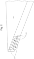
- the transducers typically but not exclusively bonded to a panel edge may come in pairs as shown in Fig 2 .
- Acoustic shear transducers 201 create mechanical stress in a transverse direction when a voltage is applied to their electrodes.
- the pairs can be configured so the stress of an individual transducer is either in the same direction to its partner (symmetric) or in an opposite direction to its partner 202 (as shown in Fig. 2 ) to create an anti-symmetric pair, and as discussed herein, this determines the symmetry of the source wave.
- the arrays 110, 111 may also include a series of top surface echelons and a series of bottom surface echelons, 301 and 302, as shown in Fig 3 .
- the alignment of the top and bottom array elements 301, 302 with respect to each other determines the symmetry of the sensing modes and aids in eliminating spurious sensing modes.
- the collimation grooves 107 confine the source waves to their respective arrays 110, 111 and reduce energy loss and other artifacts due to diffraction or spreading of the source waves.
- the collimation grooves 107 can be formed on both surfaces (e.g., top and bottom surface) of the sensor 100.
- FIG. 4 is a simplified schematic of one of the effects of diffraction relevant to acoustic touch sensors using reflection from an opposing edge.
- a source beam created by transducer 404 will spread due to diffraction with diffraction components 401 exiting the array at a maximum angle ⁇ , indicated at 402 These components will reflect from edge 403 and a fraction will return to the transducer assembly 404.
- Typical value for ⁇ are in the range of 5 to 8 degrees.
- Sensing waves 405, shown schematically, can return at the same time as the diffracted waves 407 reflected from edge 403 with comparable amplitudes causing deleterious interference.
- the transducer 501 may be present as a transducer pair mounted to the edge of the sensor as shown in Fig. 2 and, may include a pair of array elements on upper and lower (or top and bottom surfaces of the sensor) as in Fig 3 .
- the corner element 502 is typically a 45 degree reflector and serves to divert the source wave burst from the transducer 501 along the x array, into the y array 503.
- Diverter element 504 serves to prevent source waves reflecting back from edge 505 and interfering with the reception of sensing waves (see FIG. 1 ), and can be set at the same angle as the y array.
- Collimation grooves 506 confine the source waves to their respective arrays and reduce energy loss and other artifacts due to diffraction or spreading of the source waves (see, for example, Fig. 1 and accompanying description).
- the collimation grooves 506 can be etched on both surfaces (e.g., top and bottom surface) of the sensor.
- a single pulse train for the single transducer version as shown in Fig 6 with x and y coordinate detection of a touch event, as seen at 601 for the x coordinate, and as seen as 602 for the y coordinate, and are determined in a similar manner to that claimed in Knowles '327.
- Fig. 7 there is shown a dispersion diagram for shear modes, and plots phase velocity (on the y-axis) versus the product of panel thickness d times operating frequency f (on the x-axis), for the first seven shear modes in a soda-lime glass plate.
- the plot was generated from what is known as a frequency equation, and forms part of the solution of the wave equation for an elastic body, specifically a plate with zero traction at the two major surfaces.
- the Knowles '427 disclosure employed the zeroth mode, indicated at 701, for both the source and sensing modes and is the reason for the upper thickness limit for this touch sensor.
- the product fd increases, which for a fixed frequency means an increase in plate or panel thickness
- shear wave 702 shear wave 702
- a further increase in thickness results in its phase velocity approaching that of SH0.
- the array will generate SH1 as well as the SH0 sensing mode and cause deleterious interference effects. This limits plate thickness to approximately 1mm in glass.
- a further advantage of higher order source modes is that their group velocities are lower than SH0 and SAW and this implies the potential for higher touch sensor spatial resolution for fixed temporal resolution in the signal processing unit.
- FIG. 8a this illustrates a group of acoustic waves reflecting at the boundary between regions (regions 803 and 804) with different phase velocities.
- a groove 806 in practice a groove 806, several sensing wavelengths wide can replace the step. As such, grooves of sufficient depth formed at the front and back surfaces of an array can act as a waveguide for source modes.
- the maximum angle of diffracted waves to create artifacts is seven degrees.
- a third order shear source mode and a Cz of 135mils per microsecond results in an approximately 4 mil step depth.
- a groove shown in Fig 8c , 806 also provides total internal reflection as long as the groove is wider than approximately two sensing wavelengths. The groove functions similarly to a step of the same depth. In practice, collimation grooves are etched on both sides of the glass with the grooves vertically aligned. The groove depth is then one half of that calculated from Eq 2 and is easily achieved.
- a further calculation assuming the array converts third order shear source mode to a fifth order sensing mode for example shows that the groove has a negligible effect on the transmission of sensing waves through the groove.
- the sensor however may be sensitive to waves reflected from the grooves interfering with a touch response, similar to the effects of diffracted waves reflecting from an edge discussed previously. These reflected waves can be eliminated by choosing the width of the groove to be precisely two sensing wavelengths for example because a groove width that is a multiple of a half of a sensing mode wavelength will eliminate reflection due to phase cancellation.
- FIG. 9a there is shown two transducers 901 and 902, bonded to the edge of the plate. It is assumed that the stress produced by each transducer are opposite one another and uniform along the length of the transducer. The result is that any mode generated will be anti-symmetric. When the stress in each transducer is aligned only symmetric modes will be generated.
- a representation of the assumed uniform stress produced by the transducers along the edge plotted against the width d, of the panel is shown in Fig 9b . This represents an instant in time; the stress amplitude actually varies sinusoidally with time.
- the sine term is always one (1) for anti-symmetric modes and therefore a maximum occurs when the first cosine term is one and the second term is minus one.
- the third order mode is some 33% higher than the first.
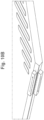
- the array response as will be shown discriminates between source modes, however if the phase velocities between a chosen and spurious modes is small enough to create wave interference additional discrimination between source modes may be obtained by reducing the transducer width below that for maximum amplitude and by beveling the edge of the glass. All higher order shear modes may be regarded as the lowest order mode SH0 propagating along the panel and reflecting off of the major surfaces at an angle determined by the mode as shown in Fig 10a .
- fd the product of panel thickness and operating frequency
- Fig. 11 there is shown a dispersion diagram that is derived from the general wave equation for an elastic plate and includes Lamb as well as transverse shear modes.
- Shear modes (SH-1- SH-6) are shown as dotted, anti-symmetric Lamb (A1-A5) as dashed and symmetric Lamb (S1-S6) as solid lines.
- Fig. 11 illustrates that when fd increases, which is necessary with thicker panels, increasing numbers of modes may exist in contrast to lowest order shear panels. Two or more sensing modes may be generated by the array from a single source at higher fd's and wave interference effects may make touch recognition impractical.
- Spurious mode suppression has been achieved in this disclosure by a combination of: deploying the mode selection properties of the array; choosing a desirable mode sufficiently distant in phase velocity from any spurious mode; and by forming vertically aligned arrays on each major surface. Additionally, if desired, a coating that attenuates out of plane wave motion and not in plane wave motion may be employed, as will be discussed.
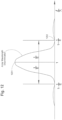
- the response peaks, as indicated at 1201, when the wavelength equals the echelon spacing l. Also the response is zero, as indicated at 1202, when the ratio of the spacing divided by the sensing wavelength increases or decreases from peak response by the reciprocal of the number of echelons, E.
- Phase velocity is equal to wavelength times frequency, hence the array response may be regarded as a phase velocity filter with pass band determined by the number of echelons along the width of an array.
- a spurious mode may then be suppressed by selecting the peak response wavelength to that of the desired mode through echelon spacing and angle, and then choosing E such that a response zero occurs at or close to a spurious mode wavelength.
- this is a very useful technique but has limitations for some desirable choices for the sensing mode. This is due to a spurious mode being so close to the desired mode in phase velocity that a very large E is required to suppress it.
- Spurious modes may be additionally suppressed even when two modes have identical phase velocities as long as the two modes have opposite symmetries through the deployment of arrays on both major surfaces.
- Both sensing and spurious modes have either symmetric or anti-symmetric wave motion as defined in Knowles '427, Fig. 1d. Referring to Fig. 13a this shows a vertically aligned array pair (top and bottom surface of panel) and Fig. 13b shows a pair aligned with a shift of half the echelon spacing.
- symmetric source modes Due to phase cancellation when the arrays are vertically aligned symmetric source modes can only generate symmetric sensing modes and anti-symmetric source modes can only generate anti-symmetric sensing modes. Conversely when the arrays are shifted by half a wavelength, symmetric source modes can only generate anti-symmetric sensing modes and anti-symmetric source modes can only generate symmetric sensing modes.
- the source and sensing mode symmetry and fd it may be arranged for the nearest spurious mode to be suppressed by array pair alignment and spurious modes further away suppressed by the array response.
- wavelength filtering properties and the vertical alignment of arrays are crucial in obtaining sensors of unrestricted thickness and improved touch attributes.
- Double arrays quadruple the amplitude of the waves returning to the transducers for a given source mode amplitude because the sensing mode exits and after reflection from an opposing edge reenters the array.
- Double arrays double the amplitude of the sensing waves per pass and due to the fact that they exit and then reenter, the amplitude increases by a factor of four. In practice this is employed to reduce the etch depth and together with collimation grooves effectively increases the upper limit to sensor size.
- Double arrays can also reduce the wavelength discrimination required of the arrays, that is the width of the array can be reduced. Generally, undesirable source wave diffraction increases as the array width is reduced, but this is mitigated by the application of collimation grooves, thus the combination of grooves and double arrays allows for narrower arrays than in previous embodiments of acoustic array sensors.
- a method has been found to further increase the discrimination between in plane and out of plane modes through the use of coatings with what is known as a non-Newtonian response to shear stress. That is the viscosity of some materials depend on the rate at which shear stress is applied.
- Some coating materials of which silicone is an example have a molecular relaxation phenomenon causing viscous losses to be greatly reduced at typical operating frequencies which range from 1MHZ to 8MHz for the sensors disclosed. Viscosity related energy losses are the predominant cause of wave damping for shear modes. With materials that exhibit this relaxation phenomena, shear wave damping is minimal at sensor operating frequencies in contrast to out of plane modes.
- radiation damping predominates; that is compressional waves form and radiate out into the coating and cause significant wave damping.
- out of plane waves are greatly attenuated and shear waves are not when traveling through a silicone coated glass plate for example.
- the coating in the form of tape with a silicone adhesive strip need be one third of an inch (1/3") wide (8.5 mm wide) or less to have a significant reduction of any residual out of plane spurious modes and is typically placed along opposing edges. This is important when the application requires the sensor to not register a touch event when a liquid is present on the surface, because as discussed, out of plane wave motion is very sensitive to liquids and even a small residual component may cause a false response especially when high touch sensitivity is required.
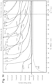
- Sensing mode selection also depends on the application. Touch screens used in outdoor settings for example likely need to respond to a touch in a wet environment but not to a finger sliding across a screen. Referring to Fig. 14 , a higher order shear mode such as SH5, (1401) is a likely choice. This allows for a higher fd and thus thicker glass which is important where, for example, vandalism may be a factor.
- the touch sensitivity of SH5 is at least three times greater than the Zohps mode touch sensor and further enhanced by the discovery that operating the sensor at an fd approximately one percent greater than peak response increases all higher order shear and Lamb mode touch sensitivities, by approximately a factor of two. This touch sensitivity is adequate for an outdoor application and, because it is a shear mode, it will be insensitive to water on the touch surface.]
- an example of a sensor of this type is the SH5 sensing mode 1401 at an fd of 12.2 (1406).
- the S2 Lamb mode 1402 is so close in phase velocity that using the array response to filter out S2 is impractical. This is due to the large number of echelons in the thickness direction required to narrow the pass band sufficiently, which implies a very wide array.
- SH5 is an anti-symmetric mode, thus if SH3 for example is selected as an anti- symmetric source mode and generated according to the disclosed design procedures, vertically aligned arrays may be deployed to suppress S2. This is because S2 is a symmetric mode and cannot be generated by a vertically aligned array pair with an anti-symmetric source mode.
- Other potential spurious modes such as SH4 1404, and A2 1405 are either suppressed by the double array configuration or filtered out by the array response.
- Touch sensors requiring high enough touch sensitivity to respond to a sliding finger can also use higher order shear as the sensing mode. This is more straightforward to accomplish with panels less than 1.5mm in thickness because touch sensitivity for shear sensing modes increases as the panel thickness decreases. With panel thicknesses below 1.5mm sensing with shear modes is adequate for most applications including tracking a sliding finger, and has the added advantage that the panel can be laminated to an underlying surface. Applications that require the highest touch sensitivity in thicker panels may utilize a higher shear source mode to a Lamb sensing mode with dominant out of plane motion at the surface. This can be accomplished for example simply by shifting the double array alignment of the previous SH3 to SH5 example. When the arrays are aligned with a half wavelength shift the SH3 source mode will generate the S3 symmetric mode and suppress SH5.
- a further example employs an out of plane Lamb sensing mode for panels 1.5mm thick and below. These are useful when thin panels and very high touch sensitivity is required and operation in the presence of water or other fluids is not necessary.
- US Patent 9,880,044 Korean, '044
- a lowest order shear to lowest order Lamb, Ao was disclosed for a liquid level sensor. Due to the benefits of collimation grooves a higher order mode such as SH1 is preferred as the source mode, but Ao, retained as the sensing mode.
- Fig. 15 these are plots showing a panel cross section of particle displacement versus distance in the plate thickness direction for Ao at various fds. These are obtained from the full wave equation for a plate with zero traction at both surfaces.
- the solid lines (those crossing the origin) represent in plane displacements and the dashed lines are out of plane or vertical displacements. In time, the displacements will move in sinusoidal motion.
- Ao has significant out of plane motion at each panel surface for all the fds shown, which is desirable in this case and we choose an fd of 3 MHz-mm (1501).
- Fig 16 there are two potential spurious modes, zeroth order shear 1603 and S0 1604 close to the operating point (1601).
- the only available higher order shear source mode at an fd of 3 is SH1 (1605).
- SH1 is anti-symmetric as is A0, but both of the potential spurious modes are symmetric. Therefore, choosing aligned double arrays will suppress SHO and S0.
- Lamb modes are selected. As previously described, higher order shear modes are preferred for source modes, and the array response plus double arrays greatly aids in selection and generation of a desired sensing mode.
- the selection of Lamb sensing modes is complicated by the fact that its dominant motion at the panel surface varies with fd, unlike shear modes.
- Fig. 17 this is similar to Fig. 14 but shown with phase velocities marked where motion at the surface for Lamb modes is entirely horizontal or in plane, 1701, or entirely out of plane, 1703. Motion is entirely in plane for all higher order symmetric Lamb modes when their phase velocity equals that of a bulk compressional wave Cl, such as indicated in 1701. These are useful modes for touch sensors that need to operate in the presence for example of water.
- the arrays can generate all kinds of unwanted modes that need to be suppressed.
- the use of two arrays, one on each surface (e.g., upper and lower or top and bottom surfaces), which arrays are aligned, or half wavelength shifted can be used to suppress unwanted modes as it can be used to determine the symmetry of the sensing modes. That is, the arrays themselves can be used to filter out unwanted modes.
- the present touch sensor improves on prior known touch sensors or touch panels in a number of ways.
- the touch sensitivity of touch panels is increased and can permit use of the sensor by gloved individuals and reduce the sensitivity of liquids (e.g., water) on the sensor.
- such a method includes operating the sensor between 0.55% and about 1-2% above array peak frequency. This increases the touch sensitivities of all higher order shear and Lamb modes.
Landscapes
- Engineering & Computer Science (AREA)
- Physics & Mathematics (AREA)
- General Engineering & Computer Science (AREA)
- Theoretical Computer Science (AREA)
- Acoustics & Sound (AREA)
- Human Computer Interaction (AREA)
- General Physics & Mathematics (AREA)
- Position Input By Displaying (AREA)
Claims (15)
- Berührungsbildschirm (100), umfassend:ein Substrat mit einer ersten und einer zweiten Oberfläche und Kanten (105), die sich zwischen der ersten und der zweiten Oberfläche erstrecken, wobei sie eine Dicke definieren;eine erste Vielzahl von Staffeln (103), die auf der ersten Oberfläche des Substrats in einem ersten Array (110) entlang einer ersten Mittellinie (109) angeordnet ist, wobei jede Staffel in der ersten Vielzahl von Staffeln in einem ersten Winkel (α) relativ zu der ersten Mittellinie gebildet ist;einen ersten Scherwandler (101), der an der Kante des Substrats montiert ist, wobei der erste Wandler konfiguriert ist, um eine Scherwelle in einem Quellenwellenmodus in einer ersten Richtung entlang der ersten Mittellinie zu erzeugen;eine zweite Vielzahl von Staffeln (103), die auf der ersten Oberfläche des Substrats in einem zweiten Array (111) entlang einer zweiten Mittellinie (112) angeordnet ist, wobei jede Staffel in der zweiten Vielzahl von Staffeln in einem zweiten Winkel (α) relativ zu der zweiten Mittellinie gebildet ist, wobei die zweite Mittellinie orthogonal zu der ersten Mittellinie ist; undeinen zweiten Scherwandler (101), der an der Kante des Substrats montiert ist, wobei der zweite Wandler konfiguriert ist, um eine Scherwelle in einem Quellenwellenmodus in einer zweiten Richtung entlang der zweiten Mittellinie zu erzeugen,wobei der Berührungsbildschirm (100) angeordnet ist, sodass sich die Scherwelle, die durch den ersten Scherwellenwandler erzeugt wird, entlang der ersten Mittellinie ausbreitet, und wobei die Scherwelle in dem ersten Winkel durch die eine oder mehreren aus der Vielzahl von Staffeln in dem ersten Array zu einer ersten Erfassungswelle reflektiert wird oder die Scherwelle in einen anderen Wellenmodus als den Quellenmodus umgewandelt wird, wobei die erste Erfassungswelle von einer Kante gegenüber der ersten Mittellinie reflektiert wird und durch den ersten Wandler erfasst wird, undwobei der Berührungsbildschirm (100) angeordnet ist, sodass sich die Scherwelle, die durch den zweiten Scherwellenwandler erzeugt wird, entlang der zweiten Mittellinie ausbreitet, und wobei die Scherwelle in dem zweiten Winkel durch die eine oder mehreren aus der Vielzahl von Staffeln in dem zweiten Array zu einer zweiten Erfassungswelle reflektiert wird oder die Scherwelle in einen anderen Wellenmodus als den Quellenmodus umgewandelt wird, wobei die zweite Erfassungswelle von einer Kante gegenüber der zweiten Mittellinie reflektiert wird und durch den zweiten Wandler erfasst wird.
- Berührungsbildschirm nach Anspruch 1, wobei der erste Wandler ein Paar von ersten Wandlern ist und der zweite Wandler ein Paar von zweiten Wandlern ist, wobei das erste Paar von Wandlern entlang der Kante montiert ist und das zweite Paar von Wandlern entlang der Kante montiert ist.
- Berührungsbildschirm nach Anspruch 2, wobei (a) die Wandler des ersten Paares von Wandlern ausgerichtet sind, um Spannungen in einer gleichen Richtung zu erzeugen, und wobei die Wandler des zweiten Paares von Wandlern ausgerichtet sind, um Spannungen in einer gleichen Richtung zu erzeugen, oder wobei (b) die Wandler des ersten Paares von Wandlern ausgerichtet sind, um Spannungen in entgegengesetzten Richtungen zu erzeugen, und wobei die Wandler des zweiten Paares von Wandlern ausgerichtet sind, um Spannungen in entgegengesetzten Richtungen zu erzeugen.
- Berührungsbildschirm nach Anspruch 1, ferner beinhaltend:eine dritte Vielzahl von Staffeln (301), die auf dem Substrat in einem dritten Array entlang einer dritten Mittellinie parallel zu der ersten Mittellinie und auf der zweiten Seite des Substrats angeordnet ist, wobei jede Staffel in der dritten Vielzahl von Staffeln in einem ersten Winkel relativ zu der dritten Mittellinie gebildet ist, undeine vierte Vielzahl von Staffeln (302), die auf dem Substrat in einem vierten Array entlang einer vierten Mittellinie parallel zu der zweiten Mittellinie und auf der zweiten Seite des Substrats angeordnet ist, wobei jede Staffel in der vierten Vielzahl von Staffeln in einem ersten Winkel relativ zu der vierten Mittellinie gebildet ist,wobei der Berührungsbildschirm angeordnet ist, sodass sich die Scherwelle, die durch den ersten Scherwellenwandler erzeugt wird, entlang der dritten Mittellinie ausbreitet, und wobei die Scherwelle in dem ersten Winkel durch die eine oder mehreren aus der Vielzahl von Staffeln in dem dritten Array zu einer ersten Erfassungswelle reflektiert wird oder die Scherwelle in einen anderen Wellenmodus als den Quellenmodus umgewandelt wird, wobei die erste Erfassungswelle von einer Kante gegenüber der dritten Mittellinie reflektiert wird und durch den ersten Wandler erfasst wird, undwobei der Berührungsbildschirm angeordnet ist, sodass sich die Scherwelle, die durch den zweiten Scherwellenwandler erzeugt wird, entlang der vierten Mittellinie ausbreitet, und wobei die Scherwelle in dem zweiten Winkel durch die eine oder mehreren aus der Vielzahl von Staffeln in dem vierten Array zu einer zweiten Erfassungswelle reflektiert wird oder die Scherwelle in einen anderen Wellenmodus als den Quellenmodus umgewandelt wird, wobei die zweite Erfassungswelle von einer Kante gegenüber der vierten Mittellinie reflektiert wird und durch den zweiten Wandler erfasst wird.
- Berührungsbildschirm nach Anspruch 4, wobei (a) die erste und die dritte Vielzahl von Staffeln zueinander ausgerichtet sind und die zweite und die vierte Vielzahl von Staffeln zueinander ausgerichtet sind, oder wobei (b) die erste und die dritte Vielzahl von Staffeln voneinander versetzt sind und die zweite und die vierte Vielzahl von Staffeln voneinander versetzt sind.
- Berührungsbildschirm nach Anspruch 1, ferner beinhaltend einen ersten Kantenumlenker, der an der Kante des Substrats an einem Ende des ersten Arrays vorgesehen ist, und einen zweiten Kantenumlenker, der an der Kante des Substrats an einem Ende des zweiten Arrays vorgesehen ist, und wobei der erste und der zweite Kantenumlenker den Quellenmodus von einem ersten Modus in einen zweiten Modus umwandeln, der sich von dem ersten Modus unterscheidet.
- Berührungsbildschirm nach Anspruch 1, ferner umfassend:eine erste Kollimationsnut (107, 506), die in dem Substrat an der Innenseite von und parallel zu dem ersten Array gebildet ist;eine zweite Kollimationsnut (107, 506), die in dem Substrat an der Innenseite von und parallel zu dem zweiten Array gebildet ist,wobei die erste Kollimationsnut (107, 506) konfiguriert ist, um die Quellenwelle auf das erste Array zu beschränken und zu ermöglichen, dass die erste Erfassungswelle über die erste Kollimationsnut (107, 506) hinaus verläuft, undwobei die zweite Kollimationsnut (107, 506) konfiguriert ist, um die Quellenwelle auf das zweite Array zu beschränken und zu ermöglichen, dass die zweite Erfassungswelle über die zweite Kollimationsnut (107, 506) hinaus verläuft.
- Berührungsbildschirm nach Anspruch 7, wobei eine Tiefe der ersten und/oder der zweiten Kollimationsnut bestimmt ist durch die Gleichung
 wobei Δd die Tiefe der ersten und/oder zweiten Kollimationsnut ist,φ ein größter Winkel ist, der für innere Totalreflexion zulässig ist,d eine Dicke des Substrats ist undA eine Ordnung einer Welle N, multipliziert mit Cz, einer Wellengeschwindigkeit nullter Ordnung, geteilt durch das Zweifache der Betriebsfrequenz ist.
 - Berührungsbildschirm nach Anspruch 7, ferner beinhaltendeine dritte Vielzahl von Staffeln, die auf dem Substrat in einem dritten Array entlang einer dritten Mittellinie parallel zu der ersten Mittellinie und auf der zweiten Seite des Substrats angeordnet ist, wobei jede Staffel in der dritten Vielzahl von Staffeln in einem ersten Winkel relativ zu der dritten Mittellinie gebildet ist;eine dritte Kollimationsnut, die in dem Substrat an der Innenseite von und parallel zu dem dritten Array gebildet ist;eine vierte Vielzahl von Staffeln, die auf dem Substrat in einem vierten Array entlang einer vierten Mittellinie parallel zu der zweiten Mittellinie und auf der zweiten Seite des Substrats angeordnet ist, wobei jede Staffel in der vierten Vielzahl von Staffeln in einem ersten Winkel relativ zu der vierten Mittellinie gebildet ist; undeine vierte Kollimationsnut, die in dem Substrat an der Innenseite von und parallel zu dem vierten Array gebildet ist,wobei der Berührungsbildschirm angeordnet ist, sodass sich die Scherwelle, die durch den ersten Scherwellenwandler erzeugt wird, entlang der dritten Mittellinie ausbreitet und wobei die Scherwelle in dem ersten Winkel durch die eine oder mehreren aus der Vielzahl von Staffeln in dem dritten Array zu einer dritten Erfassungswelle reflektiert wird oder die Scherwelle in einen anderen Wellenmodus als den Quellenmodus umgewandelt wird, wobei die dritte Erfassungswelle von einer Kante gegenüber der dritten Mittellinie reflektiert wird und durch den ersten Wandler erfasst wird,wobei der Berührungsbildschirm angeordnet ist, sodass sich die Scherwelle, die durch den zweiten Scherwellenwandler erzeugt wird, entlang der vierten Mittellinie ausbreitet und wobei die Scherwelle in dem zweiten Winkel durch die eine oder mehreren aus der Vielzahl von Staffeln in dem vierten Array zu einer vierten Erfassungswelle reflektiert wird oder die Scherwelle in einen anderen Wellenmodus als den Quellenmodus umgewandelt wird, wobei die vierte Erfassungswelle von einer Kante gegenüber der vierten Mittellinie reflektiert wird und durch den zweiten Wandler erfasst wird,wobei die erste Kollimationsnut konfiguriert ist, um die Quellenwelle auf das erste Array zu beschränken und zu ermöglichen, dass die erste Erfassungswelle über die erste Kollimationsnut hinaus verläuft,wobei die zweite Kollimationsnut konfiguriert ist, um die Quellenwelle auf das zweite Array zu beschränken und zu ermöglichen, dass die zweite Erfassungswelle über die zweite Kollimationsnut hinaus verläuft,wobei die dritte Kollimationsnut konfiguriert ist, um die Quellenwelle auf das dritte Array zu beschränken und zu ermöglichen, dass die dritte Erfassungswelle über die dritte Kollimationsnut hinaus verläuft, undwobei die vierte Kollimationsnut konfiguriert ist, um die Quellenwelle auf das vierte Array zu beschränken und zu ermöglichen, dass die vierte Erfassungswelle über die vierte Kollimationsnut hinaus verläuft.
- Berührungsbildschirm nach Anspruch 9, wobei eine Tiefe der dritten und/oder der vierten Kollimationsnut bestimmt ist durch die Gleichung
 wobei Δd die Tiefe der dritten und/oder vierten Kollimationsnut ist,φ ein größter Winkel ist, der für innere Totalreflexion zulässig ist,d eine Dicke des Substrats ist undA eine Ordnung einer Welle N, multipliziert mit Cz, einer Wellengeschwindigkeit nullter Ordnung, geteilt durch das Zweifache der Betriebsfrequenz ist.
 - Berührungsbildschirm nach Anspruch 1,wobei der erste Scherwandler ein erstes Paar von Scherwandlern ist, das an der Kante des Substrats montiert ist, wobei das erste Paar von Wandlern konfiguriert ist, um Scherwellen in einem Quellenwellenmodus in einer ersten Richtung entlang der ersten Mittellinie zu erzeugen;wobei der zweite Scherwandler ein zweites Paar von Scherwandlern ist, das an der Kante des Substrats montiert ist, wobei das zweite Paar von Wandlern konfiguriert ist, um Scherwellen in einem Quellenwellenmodus in einer zweiten Richtung entlang der zweiten Mittellinie zu erzeugen,wobei der Berührungsbildschirm angeordnet ist, sodass sich die Scherwellen, die durch das erste Paar von Scherwellenwandlern erzeugt werden, entlang der ersten Mittellinie ausbreiten, und wobei die Scherwellen in dem ersten Winkel durch die eine oder mehreren aus der Vielzahl von Staffeln in dem ersten Array zu ersten Erfassungswellen reflektiert werden oder die Scherwellen in einen anderen Wellenmodus als den Quellenmodus umgewandelt werden, wobei die ersten Erfassungswellen von einer Kante gegenüber der ersten Mittellinie reflektiert werden und durch das erste Paar von Wandlern erfasst werden, undwobei der Berührungsbildschirm angeordnet ist, sodass sich die Scherwellen, die durch das zweite Paar von Scherwellenwandlern erzeugt werden, entlang der zweiten Mittellinie ausbreiten, und wobei die Scherwellen in dem zweiten Winkel durch die eine oder mehreren aus der Vielzahl von Staffeln in dem zweiten Array zu zweiten Erfassungswellen reflektiert werden oder die Scherwellen in einen anderen Wellenmodus als den Quellenmodus umgewandelt werden, wobei die zweiten Erfassungswellen von einer Kante gegenüber der zweiten Mittellinie reflektiert werden und durch das zweite Paar von Wandlern erfasst werden.
- Berührungsbildschirm nach Anspruch 11, wobei die Wandler des ersten Paares von Wandlern an der Kante des Substrats quer zu einer Richtung des ersten Arrays montiert sind und konfiguriert sind, um Wellen in antisymmetrischem Schermodus zu erzeugen, wobei die Wandler des ersten Paares von Wandlern um einen Abstand voneinander beabstandet sind, der bestimmt ist durch die Gleichung
 wobei Bn eine Amplitude jeder Welle des Schermodus ist,N eine Ordnung des Modus ist,d eine Dicke des Substrats ist,b ein Abstand von einer Mittellinie des Substrats zu einer Außenkante der Wandler ist undc ein Abstand von einer Innenkante der Wandler zu einer Mittellinie des Substrats ist,und wobei optional die Wandler des zweiten Paares von Wandlern an der Kante des Substrats quer zu einer Richtung des zweiten Arrays montiert sind und konfiguriert sind, um Wellen in antisymmetrischem Schermodus zu erzeugen, wobei die Wandler des ersten Paares von Wandlern um einen Abstand voneinander beabstandet sind, der bestimmt ist durch die Gleichung
 wobei Bn eine Amplitude jeder Welle des Schermodus ist,N eine Ordnung des Modus ist,d eine Dicke des Substrats ist,b ein Abstand von einer Mittellinie des Substrats zu einer Außenkante der Wandler ist und c ein Abstand von einer Innenkante der Wandler zu einer Mittellinie des Substrats ist.
 - Berührungsbildschirm nach Anspruch 11, wobei die Wandler des ersten Paares von Wandlern an der Kante des Substrats quer zu einer Richtung des ersten Arrays montiert sind und konfiguriert sind, um Wellen in symmetrischem Schermodus zu erzeugen, wobei die Wandler des ersten Paares von Wandlern um einen Abstand voneinander beabstandet sind, der bestimmt ist durch die Gleichung
 wobei Bn eine Amplitude jeder Welle des Schermodus ist,N eine Ordnung des Modus ist,d eine Dicke des Substrats ist,b ein Abstand von einer Mittellinie des Substrats zu einer Außenkante der Wandler ist undc ein Abstand von einer Innenkante der Wandler zu einer Mittellinie des Substrats ist,wobei optional die Wandler des zweiten Paares von Wandlern an der Kante des Substrats quer zu einer Richtung des zweiten Arrays montiert sind und konfiguriert sind, um Wellen in symmetrischem Schermodus zu erzeugen, wobei die Wandler des ersten Paares von Wandlern um einen Abstand voneinander beabstandet sind, der bestimmt ist durch die Gleichung
 wobei Bn eine Amplitude jeder Welle des Schermodus ist,N eine Ordnung des Modus ist,d eine Dicke des Substrats ist,b ein Abstand von einer Mittellinie des Substrats zu einer Außenkante der Wandler ist undc ein Abstand von einer Innenkante der Wandler zu einer Mittellinie des Substrats ist.
 - Berührungsbildschirm nach einem der Ansprüche 1, 7 oder 11, ferner beinhaltend eine nicht-Newtonsche Beschichtung auf dem Substrat.
- Berührungsbildschirm nach Anspruch 11, wobei die Kante erste und zweite Abschrägungen zwischen der ersten und der zweiten Oberfläche aufweist, wobei die erste und die zweite Abschrägung in einem Winkel θ zueinander zwischen und ohne 0 Grad und 90 Grad gebildet sind, wobei ein erster Wandler des ersten Paares von Wandlern an der ersten Abschrägung montiert ist und ein zweiter Wandler des zweiten Paares von Wandlern an der zweiten Abschrägung montiert ist, wobei optional der Winkel θ bestimmt ist durch die Gleichung
 wobei f Frequenz der Quellenwelle ist,fco die Grenzfrequenz gegeben durch
 N eine Ordnung des Modus ist, undCz eine Phasengeschwindigkeit eines Schermodus nullter Ordnung ist undd eine Dicke des Substrats ist.
Applications Claiming Priority (2)
| Application Number | Priority Date | Filing Date | Title |
|---|---|---|---|
| US17/240,190 US11320938B1 (en) | 2021-04-26 | 2021-04-26 | Acoustic mode touch panels with selectable characteristics |
| PCT/US2022/024399 WO2022231835A1 (en) | 2021-04-26 | 2022-04-12 | Acoustic mode touch panels with selectable characteristics |
Publications (3)
| Publication Number | Publication Date |
|---|---|
| EP4330801A1 EP4330801A1 (de) | 2024-03-06 |
| EP4330801B1 true EP4330801B1 (de) | 2025-06-11 |
| EP4330801C0 EP4330801C0 (de) | 2025-06-11 |
Family
ID=81385268
Family Applications (1)
| Application Number | Title | Priority Date | Filing Date |
|---|---|---|---|
| EP22720209.0A Active EP4330801B1 (de) | 2021-04-26 | 2022-04-12 | Berührungsbildschirme mit akustischem modus und wählbaren eigenschaften |
Country Status (3)
| Country | Link |
|---|---|
| US (1) | US11320938B1 (de) |
| EP (1) | EP4330801B1 (de) |
| WO (1) | WO2022231835A1 (de) |
Families Citing this family (2)
| Publication number | Priority date | Publication date | Assignee | Title |
|---|---|---|---|---|
| US11320939B1 (en) * | 2021-07-23 | 2022-05-03 | Texzec, Inc. | Touch sensor with multiple modes of operation, increased reliability and ease of integration |
| US11808616B1 (en) | 2023-04-14 | 2023-11-07 | Texzec, Inc. | Acoustic array liquid level sensor |
Family Cites Families (14)
| Publication number | Priority date | Publication date | Assignee | Title |
|---|---|---|---|---|
| US4642423A (en) | 1985-08-30 | 1987-02-10 | Zenith Electronics Corporation | Touch control system for use with or having a three-dimensionally curved touch surface |
| US5072427A (en) | 1990-11-16 | 1991-12-10 | Exzec Inc. | Acoustic touch position sensor with shear to lamb wave conversion |
| US5177327A (en) | 1990-11-16 | 1993-01-05 | Exzec, Inc. | Acoustic touch position sensor using shear wave propagation |
| US5162618A (en) | 1990-11-16 | 1992-11-10 | Exzec, Inc. | Acoustic touch position sensor with first order lamb wave reflective arrays |
| JP3300856B2 (ja) * | 1996-08-12 | 2002-07-08 | イーエルオー・タッチシステムズ・インコーポレイテッド | 複数の相互非直交波を使用した音響式状態センサ |
| KR100542801B1 (ko) * | 1996-12-25 | 2006-08-04 | 터치 패널 시스템즈 코포레이션 | 음향터치스크린용격자트랜스듀서 |
| US6087599A (en) * | 1997-11-24 | 2000-07-11 | The Whitaker Corporation | Touch panels having plastic substrates |
| JP4090329B2 (ja) * | 2002-11-13 | 2008-05-28 | タッチパネル・システムズ株式会社 | 音響波型接触検出装置 |
| DE10323729A1 (de) * | 2003-05-26 | 2004-12-16 | Institut Für Neue Materialien Gem. Gmbh | Zusammensetzung mit Nichtnewtonschem Verhalten |
| WO2013074686A1 (en) * | 2011-11-14 | 2013-05-23 | Street Smart Sensors Llc | Acoustic array sensor |
| WO2013086510A1 (en) * | 2011-12-09 | 2013-06-13 | Street Smart Sensors, Llc | Touch screen with acoustic mode reflective and conversion arrays |
| US9164627B2 (en) * | 2012-03-09 | 2015-10-20 | Elo Touch Solutions, Inc. | Acoustic touch apparatus with variable thickness substrate |
| US9507464B2 (en) | 2013-03-15 | 2016-11-29 | Elo Touch Solutions, Inc. | Acoustic touch apparatus and methods using touch sensitive lamb waves |
| US11320939B1 (en) * | 2021-07-23 | 2022-05-03 | Texzec, Inc. | Touch sensor with multiple modes of operation, increased reliability and ease of integration |
-
2021
- 2021-04-26 US US17/240,190 patent/US11320938B1/en active Active
-
2022
- 2022-04-12 EP EP22720209.0A patent/EP4330801B1/de active Active
- 2022-04-12 WO PCT/US2022/024399 patent/WO2022231835A1/en not_active Ceased
Also Published As
| Publication number | Publication date |
|---|---|
| EP4330801C0 (de) | 2025-06-11 |
| US11320938B1 (en) | 2022-05-03 |
| EP4330801A1 (de) | 2024-03-06 |
| WO2022231835A1 (en) | 2022-11-03 |
Similar Documents
| Publication | Publication Date | Title |
|---|---|---|
| CA2214119C (en) | Acoustic touch position sensor using higher order horizontally polarized shear wave propagation | |
| US5739479A (en) | Gentle-bevel flat acoustic wave touch sensor | |
| EP0950234B1 (de) | Gitterwandler für akustischen berührungsbildschirm | |
| US8994696B2 (en) | Acoustic touch apparatus with addressable multi-touch capability | |
| CN100403397C (zh) | 具有叠层衬底的声触摸传感器 | |
| US11320938B1 (en) | Acoustic mode touch panels with selectable characteristics | |
| US9430100B2 (en) | Acoustic touch apparatus with multi-touch capability | |
| EP2823383B1 (de) | Akustische berührungsvorrichtung mit substrat mit variabler dicke | |
| CN107238961B (zh) | 一种触摸显示面板及显示装置 | |
| KR940704038A (ko) | 음파 접촉 위치 감지기용 접촉 패널(touch panel for acoustic touch position sensor) | |
| KR19980701629A (ko) | 저손실 투명 기판을 사용하는 음향 터치 위치 센서 | |
| WO1992009051A1 (en) | Acoustic touch position sensor with shear to lamb wave conversion | |
| EP4374243B1 (de) | Berührungssensor mit mehreren betriebsmodi, erhöhter zuverlässigkeit und erleichterung der integration | |
| US6070468A (en) | Micromachined ultrasonic leaky wave air transducers | |
| US5714962A (en) | Array antenna | |
| Deschamps et al. | Reflection and refraction of a heterogeneous plane wave by a solid layer | |
| US3967221A (en) | Surface acoustic wave delay line with bulk wave discrimination | |
| US5981938A (en) | Opto-electronic device | |
| US4916348A (en) | Surface acoustic wave scattering grating | |
| JP3749608B2 (ja) | タッチ式座標入力装置 | |
| Emura | Effects of transition zone and low velocity layer on frequency spectra of plane SH waves | |
| JP2001014092A (ja) | 音響的接触検出装置 | |
| MXPA99005934A (en) | Grating transducer for acoustic touchscreen | |
| JP2003233050A (ja) | 音響光学素子 | |
| JPH05267988A (ja) | 弾性表面波の散乱器 |
Legal Events
| Date | Code | Title | Description |
|---|---|---|---|
| STAA | Information on the status of an ep patent application or granted ep patent |
Free format text: STATUS: UNKNOWN |
|
| STAA | Information on the status of an ep patent application or granted ep patent |
Free format text: STATUS: THE INTERNATIONAL PUBLICATION HAS BEEN MADE |
|
| PUAI | Public reference made under article 153(3) epc to a published international application that has entered the european phase |
Free format text: ORIGINAL CODE: 0009012 |
|
| STAA | Information on the status of an ep patent application or granted ep patent |
Free format text: STATUS: REQUEST FOR EXAMINATION WAS MADE |
|
| 17P | Request for examination filed |
Effective date: 20231026 |
|
| AK | Designated contracting states |
Kind code of ref document: A1 Designated state(s): AL AT BE BG CH CY CZ DE DK EE ES FI FR GB GR HR HU IE IS IT LI LT LU LV MC MK MT NL NO PL PT RO RS SE SI SK SM TR |
|
| DAV | Request for validation of the european patent (deleted) | ||
| DAX | Request for extension of the european patent (deleted) | ||
| GRAP | Despatch of communication of intention to grant a patent |
Free format text: ORIGINAL CODE: EPIDOSNIGR1 |
|
| STAA | Information on the status of an ep patent application or granted ep patent |
Free format text: STATUS: GRANT OF PATENT IS INTENDED |
|
| INTG | Intention to grant announced |
Effective date: 20250120 |
|
| GRAS | Grant fee paid |
Free format text: ORIGINAL CODE: EPIDOSNIGR3 |
|
| GRAA | (expected) grant |
Free format text: ORIGINAL CODE: 0009210 |
|
| STAA | Information on the status of an ep patent application or granted ep patent |
Free format text: STATUS: THE PATENT HAS BEEN GRANTED |
|
| AK | Designated contracting states |
Kind code of ref document: B1 Designated state(s): AL AT BE BG CH CY CZ DE DK EE ES FI FR GB GR HR HU IE IS IT LI LT LU LV MC MK MT NL NO PL PT RO RS SE SI SK SM TR |
|
| REG | Reference to a national code |
Ref country code: GB Ref legal event code: FG4D |
|
| REG | Reference to a national code |
Ref country code: CH Ref legal event code: EP |
|
| REG | Reference to a national code |
Ref country code: DE Ref legal event code: R096 Ref document number: 602022015820 Country of ref document: DE |
|
| REG | Reference to a national code |
Ref country code: IE Ref legal event code: FG4D |
|
| U01 | Request for unitary effect filed |
Effective date: 20250710 |
|
| U07 | Unitary effect registered |
Designated state(s): AT BE BG DE DK EE FI FR IT LT LU LV MT NL PT RO SE SI Effective date: 20250730 |
|
| PG25 | Lapsed in a contracting state [announced via postgrant information from national office to epo] |
Ref country code: ES Free format text: LAPSE BECAUSE OF FAILURE TO SUBMIT A TRANSLATION OF THE DESCRIPTION OR TO PAY THE FEE WITHIN THE PRESCRIBED TIME-LIMIT Effective date: 20250611 |
|
| PG25 | Lapsed in a contracting state [announced via postgrant information from national office to epo] |
Ref country code: GR Free format text: LAPSE BECAUSE OF FAILURE TO SUBMIT A TRANSLATION OF THE DESCRIPTION OR TO PAY THE FEE WITHIN THE PRESCRIBED TIME-LIMIT Effective date: 20250912 Ref country code: NO Free format text: LAPSE BECAUSE OF FAILURE TO SUBMIT A TRANSLATION OF THE DESCRIPTION OR TO PAY THE FEE WITHIN THE PRESCRIBED TIME-LIMIT Effective date: 20250911 |
|
| PG25 | Lapsed in a contracting state [announced via postgrant information from national office to epo] |
Ref country code: HR Free format text: LAPSE BECAUSE OF FAILURE TO SUBMIT A TRANSLATION OF THE DESCRIPTION OR TO PAY THE FEE WITHIN THE PRESCRIBED TIME-LIMIT Effective date: 20250611 |
|
| PG25 | Lapsed in a contracting state [announced via postgrant information from national office to epo] |
Ref country code: RS Free format text: LAPSE BECAUSE OF FAILURE TO SUBMIT A TRANSLATION OF THE DESCRIPTION OR TO PAY THE FEE WITHIN THE PRESCRIBED TIME-LIMIT Effective date: 20250911 |
|
| PG25 | Lapsed in a contracting state [announced via postgrant information from national office to epo] |
Ref country code: IS Free format text: LAPSE BECAUSE OF FAILURE TO SUBMIT A TRANSLATION OF THE DESCRIPTION OR TO PAY THE FEE WITHIN THE PRESCRIBED TIME-LIMIT Effective date: 20251011 |
|
| PG25 | Lapsed in a contracting state [announced via postgrant information from national office to epo] |
Ref country code: SM Free format text: LAPSE BECAUSE OF FAILURE TO SUBMIT A TRANSLATION OF THE DESCRIPTION OR TO PAY THE FEE WITHIN THE PRESCRIBED TIME-LIMIT Effective date: 20250611 |
|
| PG25 | Lapsed in a contracting state [announced via postgrant information from national office to epo] |
Ref country code: CZ Free format text: LAPSE BECAUSE OF FAILURE TO SUBMIT A TRANSLATION OF THE DESCRIPTION OR TO PAY THE FEE WITHIN THE PRESCRIBED TIME-LIMIT Effective date: 20250611 |
|
| PG25 | Lapsed in a contracting state [announced via postgrant information from national office to epo] |
Ref country code: PL Free format text: LAPSE BECAUSE OF FAILURE TO SUBMIT A TRANSLATION OF THE DESCRIPTION OR TO PAY THE FEE WITHIN THE PRESCRIBED TIME-LIMIT Effective date: 20250611 |
|
| PG25 | Lapsed in a contracting state [announced via postgrant information from national office to epo] |
Ref country code: SK Free format text: LAPSE BECAUSE OF FAILURE TO SUBMIT A TRANSLATION OF THE DESCRIPTION OR TO PAY THE FEE WITHIN THE PRESCRIBED TIME-LIMIT Effective date: 20250611 |
|
| PLBE | No opposition filed within time limit |
Free format text: ORIGINAL CODE: 0009261 |
|
| STAA | Information on the status of an ep patent application or granted ep patent |
Free format text: STATUS: NO OPPOSITION FILED WITHIN TIME LIMIT |
|
| REG | Reference to a national code |
Ref country code: CH Ref legal event code: L10 Free format text: ST27 STATUS EVENT CODE: U-0-0-L10-L00 (AS PROVIDED BY THE NATIONAL OFFICE) Effective date: 20260423 |