EP4330019B1 - Verpackung, bei der die verschweissung im aufdruck verborgen ist, und entsprechendes herstellungsverfahren - Google Patents
Verpackung, bei der die verschweissung im aufdruck verborgen ist, und entsprechendes herstellungsverfahren Download PDFInfo
- Publication number
- EP4330019B1 EP4330019B1 EP22723193.3A EP22723193A EP4330019B1 EP 4330019 B1 EP4330019 B1 EP 4330019B1 EP 22723193 A EP22723193 A EP 22723193A EP 4330019 B1 EP4330019 B1 EP 4330019B1
- Authority
- EP
- European Patent Office
- Prior art keywords
- sheet
- tubular body
- image
- edge
- lateral
- Prior art date
- Legal status (The legal status is an assumption and is not a legal conclusion. Google has not performed a legal analysis and makes no representation as to the accuracy of the status listed.)
- Active
Links
Images


Classifications
-
- B—PERFORMING OPERATIONS; TRANSPORTING
- B29—WORKING OF PLASTICS; WORKING OF SUBSTANCES IN A PLASTIC STATE IN GENERAL
- B29C—SHAPING OR JOINING OF PLASTICS; SHAPING OF MATERIAL IN A PLASTIC STATE, NOT OTHERWISE PROVIDED FOR; AFTER-TREATMENT OF THE SHAPED PRODUCTS, e.g. REPAIRING
- B29C66/00—General aspects of processes or apparatus for joining preformed parts
- B29C66/01—General aspects dealing with the joint area or with the area to be joined
- B29C66/05—Particular design of joint configurations
- B29C66/10—Particular design of joint configurations particular design of the joint cross-sections
- B29C66/11—Joint cross-sections comprising a single joint-segment, i.e. one of the parts to be joined comprising a single joint-segment in the joint cross-section
- B29C66/114—Single butt joints
- B29C66/1142—Single butt to butt joints
-
- B—PERFORMING OPERATIONS; TRANSPORTING
- B29—WORKING OF PLASTICS; WORKING OF SUBSTANCES IN A PLASTIC STATE IN GENERAL
- B29C—SHAPING OR JOINING OF PLASTICS; SHAPING OF MATERIAL IN A PLASTIC STATE, NOT OTHERWISE PROVIDED FOR; AFTER-TREATMENT OF THE SHAPED PRODUCTS, e.g. REPAIRING
- B29C48/00—Extrusion moulding, i.e. expressing the moulding material through a die or nozzle which imparts the desired form; Apparatus therefor
- B29C48/15—Extrusion moulding, i.e. expressing the moulding material through a die or nozzle which imparts the desired form; Apparatus therefor incorporating preformed parts or layers, e.g. extrusion moulding around inserts
- B29C48/151—Coating hollow articles
- B29C48/152—Coating hollow articles the inner surfaces thereof
-
- B—PERFORMING OPERATIONS; TRANSPORTING
- B29—WORKING OF PLASTICS; WORKING OF SUBSTANCES IN A PLASTIC STATE IN GENERAL
- B29C—SHAPING OR JOINING OF PLASTICS; SHAPING OF MATERIAL IN A PLASTIC STATE, NOT OTHERWISE PROVIDED FOR; AFTER-TREATMENT OF THE SHAPED PRODUCTS, e.g. REPAIRING
- B29C53/00—Shaping by bending, folding, twisting, straightening or flattening; Apparatus therefor
- B29C53/005—Shaping by bending, folding, twisting, straightening or flattening; Apparatus therefor characterised by the choice of material
-
- B—PERFORMING OPERATIONS; TRANSPORTING
- B29—WORKING OF PLASTICS; WORKING OF SUBSTANCES IN A PLASTIC STATE IN GENERAL
- B29C—SHAPING OR JOINING OF PLASTICS; SHAPING OF MATERIAL IN A PLASTIC STATE, NOT OTHERWISE PROVIDED FOR; AFTER-TREATMENT OF THE SHAPED PRODUCTS, e.g. REPAIRING
- B29C53/00—Shaping by bending, folding, twisting, straightening or flattening; Apparatus therefor
- B29C53/36—Bending and joining, e.g. for making hollow articles
- B29C53/38—Bending and joining, e.g. for making hollow articles by bending sheets or strips at right angles to the longitudinal axis of the article being formed and joining the edges
- B29C53/385—Bending and joining, e.g. for making hollow articles by bending sheets or strips at right angles to the longitudinal axis of the article being formed and joining the edges using several sheets to form the circumference
-
- B—PERFORMING OPERATIONS; TRANSPORTING
- B29—WORKING OF PLASTICS; WORKING OF SUBSTANCES IN A PLASTIC STATE IN GENERAL
- B29C—SHAPING OR JOINING OF PLASTICS; SHAPING OF MATERIAL IN A PLASTIC STATE, NOT OTHERWISE PROVIDED FOR; AFTER-TREATMENT OF THE SHAPED PRODUCTS, e.g. REPAIRING
- B29C53/00—Shaping by bending, folding, twisting, straightening or flattening; Apparatus therefor
- B29C53/36—Bending and joining, e.g. for making hollow articles
- B29C53/38—Bending and joining, e.g. for making hollow articles by bending sheets or strips at right angles to the longitudinal axis of the article being formed and joining the edges
- B29C53/40—Bending and joining, e.g. for making hollow articles by bending sheets or strips at right angles to the longitudinal axis of the article being formed and joining the edges for articles of definite length, i.e. discrete articles
-
- B—PERFORMING OPERATIONS; TRANSPORTING
- B29—WORKING OF PLASTICS; WORKING OF SUBSTANCES IN A PLASTIC STATE IN GENERAL
- B29C—SHAPING OR JOINING OF PLASTICS; SHAPING OF MATERIAL IN A PLASTIC STATE, NOT OTHERWISE PROVIDED FOR; AFTER-TREATMENT OF THE SHAPED PRODUCTS, e.g. REPAIRING
- B29C65/00—Joining or sealing of preformed parts, e.g. welding of plastics materials; Apparatus therefor
- B29C65/02—Joining or sealing of preformed parts, e.g. welding of plastics materials; Apparatus therefor by heating, with or without pressure
- B29C65/18—Joining or sealing of preformed parts, e.g. welding of plastics materials; Apparatus therefor by heating, with or without pressure using heated tools
- B29C65/20—Joining or sealing of preformed parts, e.g. welding of plastics materials; Apparatus therefor by heating, with or without pressure using heated tools with direct contact, e.g. using "mirror"
-
- B—PERFORMING OPERATIONS; TRANSPORTING
- B29—WORKING OF PLASTICS; WORKING OF SUBSTANCES IN A PLASTIC STATE IN GENERAL
- B29C—SHAPING OR JOINING OF PLASTICS; SHAPING OF MATERIAL IN A PLASTIC STATE, NOT OTHERWISE PROVIDED FOR; AFTER-TREATMENT OF THE SHAPED PRODUCTS, e.g. REPAIRING
- B29C66/00—General aspects of processes or apparatus for joining preformed parts
- B29C66/01—General aspects dealing with the joint area or with the area to be joined
- B29C66/02—Preparation of the material, in the area to be joined, prior to joining or welding
- B29C66/022—Mechanical pre-treatments, e.g. reshaping
- B29C66/0224—Mechanical pre-treatments, e.g. reshaping with removal of material
- B29C66/02241—Cutting, e.g. by using waterjets, or sawing
-
- B—PERFORMING OPERATIONS; TRANSPORTING
- B29—WORKING OF PLASTICS; WORKING OF SUBSTANCES IN A PLASTIC STATE IN GENERAL
- B29C—SHAPING OR JOINING OF PLASTICS; SHAPING OF MATERIAL IN A PLASTIC STATE, NOT OTHERWISE PROVIDED FOR; AFTER-TREATMENT OF THE SHAPED PRODUCTS, e.g. REPAIRING
- B29C66/00—General aspects of processes or apparatus for joining preformed parts
- B29C66/01—General aspects dealing with the joint area or with the area to be joined
- B29C66/03—After-treatments in the joint area
- B29C66/034—Thermal after-treatments
- B29C66/0342—Cooling, e.g. transporting through welding and cooling zone
-
- B—PERFORMING OPERATIONS; TRANSPORTING
- B29—WORKING OF PLASTICS; WORKING OF SUBSTANCES IN A PLASTIC STATE IN GENERAL
- B29D—PRODUCING PARTICULAR ARTICLES FROM PLASTICS OR FROM SUBSTANCES IN A PLASTIC STATE
- B29D23/00—Producing tubular articles
- B29D23/20—Flexible squeeze tubes, e.g. for cosmetics
-
- B—PERFORMING OPERATIONS; TRANSPORTING
- B65—CONVEYING; PACKING; STORING; HANDLING THIN OR FILAMENTARY MATERIAL
- B65D—CONTAINERS FOR STORAGE OR TRANSPORT OF ARTICLES OR MATERIALS, e.g. BAGS, BARRELS, BOTTLES, BOXES, CANS, CARTONS, CRATES, DRUMS, JARS, TANKS, HOPPERS, FORWARDING CONTAINERS; ACCESSORIES, CLOSURES, OR FITTINGS THEREFOR; PACKAGING ELEMENTS; PACKAGES
- B65D3/00—Rigid or semi-rigid containers having bodies or peripheral walls of curved or partially-curved cross-section made by winding or bending paper without folding along defined lines
- B65D3/02—Rigid or semi-rigid containers having bodies or peripheral walls of curved or partially-curved cross-section made by winding or bending paper without folding along defined lines characterised by shape
- B65D3/04—Rigid or semi-rigid containers having bodies or peripheral walls of curved or partially-curved cross-section made by winding or bending paper without folding along defined lines characterised by shape essentially cylindrical
-
- B—PERFORMING OPERATIONS; TRANSPORTING
- B65—CONVEYING; PACKING; STORING; HANDLING THIN OR FILAMENTARY MATERIAL
- B65D—CONTAINERS FOR STORAGE OR TRANSPORT OF ARTICLES OR MATERIALS, e.g. BAGS, BARRELS, BOTTLES, BOXES, CANS, CARTONS, CRATES, DRUMS, JARS, TANKS, HOPPERS, FORWARDING CONTAINERS; ACCESSORIES, CLOSURES, OR FITTINGS THEREFOR; PACKAGING ELEMENTS; PACKAGES
- B65D35/00—Pliable tubular containers adapted to be permanently or temporarily deformed to expel contents, e.g. collapsible tubes for toothpaste or other plastic or semi-liquid material; Holders therefor
- B65D35/02—Body construction
-
- B—PERFORMING OPERATIONS; TRANSPORTING
- B65—CONVEYING; PACKING; STORING; HANDLING THIN OR FILAMENTARY MATERIAL
- B65D—CONTAINERS FOR STORAGE OR TRANSPORT OF ARTICLES OR MATERIALS, e.g. BAGS, BARRELS, BOTTLES, BOXES, CANS, CARTONS, CRATES, DRUMS, JARS, TANKS, HOPPERS, FORWARDING CONTAINERS; ACCESSORIES, CLOSURES, OR FITTINGS THEREFOR; PACKAGING ELEMENTS; PACKAGES
- B65D75/00—Packages comprising articles or materials partially or wholly enclosed in strips, sheets, blanks, tubes or webs of flexible sheet material, e.g. in folded wrappers
- B65D75/04—Articles or materials wholly enclosed in single sheets or wrapper blanks
- B65D75/06—Articles or materials wholly enclosed in single sheets or wrapper blanks in sheets or blanks initially folded to form tubes
-
- B—PERFORMING OPERATIONS; TRANSPORTING
- B29—WORKING OF PLASTICS; WORKING OF SUBSTANCES IN A PLASTIC STATE IN GENERAL
- B29C—SHAPING OR JOINING OF PLASTICS; SHAPING OF MATERIAL IN A PLASTIC STATE, NOT OTHERWISE PROVIDED FOR; AFTER-TREATMENT OF THE SHAPED PRODUCTS, e.g. REPAIRING
- B29C2795/00—Printing on articles made from plastics or substances in a plastic state
- B29C2795/002—Printing on articles made from plastics or substances in a plastic state before shaping
-
- B—PERFORMING OPERATIONS; TRANSPORTING
- B29—WORKING OF PLASTICS; WORKING OF SUBSTANCES IN A PLASTIC STATE IN GENERAL
- B29L—INDEXING SCHEME ASSOCIATED WITH SUBCLASS B29C, RELATING TO PARTICULAR ARTICLES
- B29L2023/00—Tubular articles
- B29L2023/20—Flexible squeeze tubes, e.g. for cosmetics
-
- B—PERFORMING OPERATIONS; TRANSPORTING
- B65—CONVEYING; PACKING; STORING; HANDLING THIN OR FILAMENTARY MATERIAL
- B65D—CONTAINERS FOR STORAGE OR TRANSPORT OF ARTICLES OR MATERIALS, e.g. BAGS, BARRELS, BOTTLES, BOXES, CANS, CARTONS, CRATES, DRUMS, JARS, TANKS, HOPPERS, FORWARDING CONTAINERS; ACCESSORIES, CLOSURES, OR FITTINGS THEREFOR; PACKAGING ELEMENTS; PACKAGES
- B65D2203/00—Decoration means, markings, information elements, contents indicators
Definitions
- the invention falls within the field of packagings formed by means of welded or bonded printed sheets. It relates more specifically to the packagings comprising a tubular body obtained by butt-welding or bonding of a sheet.
- the invention applies to the field of packaging and in particular that of the recyclable flexible tubes intended to contain cream or paste products; or that of the cans replacing aluminium to contain liquids; or that of the flasks for cosmetic products.
- the publications EP2720849 and EP2720850 teach a method for butt-welding a multilayer sheet to form a tubular body.
- the publication EP2720849 proposes bevel-cutting the edges with different angles so as to form a slight overlap of the edges of the sheet in the weld zone.
- the publication EP2720849 for its part, teaches bevel-cutting the edges of the sheet and exerting a circumferential pressure on said edges during the welding operation. These publications do not teach how to obtain a continuity of the design in the welded zone to conceal the weld.
- EP2007567 , EP2004506 , EP2004389 notably propose adding a reinforcing strip at the butt weld at the ends in order for the weld to have a sufficient strength.
- the butt-welding proposed in these publications also allows for a tubular body that has a decoration in the weld zone.
- the possibility of masking the weld zone by the decoration is a great advantage in the field of packaging, above all when it is intended for the cosmetic sector.
- the prior art does not make it possible to obtain continuity of the decoration on the two sides of the weld with great precision.
- the publication EP3300881 proposes a method for cutting the edges of the printed sheet before welding to improve the aesthetics of the welding of the ends of a printed sheet; said ends being lap-welded.
- the method proposes using the edges of the printed snapshot to control the position of the cut. This method makes it possible to improve the aesthetics of the welds by overlap but cannot be applied to the butt-welding to resolve the problem of offset of the patterns on either side of the weld.
- the aim of the invention is to improve the known methods.
- the aim of the invention is to propose simple means for producing a tubular body decorated over its entire surface in which the weld is not visible.
- the invention makes it possible to remedy the abovementioned drawbacks.
- the invention makes it possible to produce a butt weld with a continuity of the design in the welded zone in order to conceal the weld and avoid the visible offsets which occur in the state of the art.
- the invention relates to a method for producing tubes by welding of a printed sheet and that have a so-called "360°” decoration; that is to say one which extends over its entire periphery.
- the invention relates notably to a method that makes it possible to conceal the weld zone in the design.
- the invention relates to a method for manufacturing a tubular body continuously, consisting at least in printing a series of successive images on a reel-packaged sheet; in paying out said sheet thus defining a scrolling direction, in cutting the lateral edges of said sheet in order for the remaining width of the sheet to be matched with the diameter of the tubular body to be produced, in shaping the sheet into tubular geometry, in butt-welding the lateral edges of the sheet, then in cutting the tubular body at right angles to the scrolling direction and in synchronism with the images.
- the invention is characterized notably by the fact that the width of the printed image on the sheet is greater than the perimeter of the tubular body to be produced and by the fact that a first part situated on the left edge of the image is identical to a second part situated on the right edge of the image; said left and right parts forming two parallel lateral strips of identical width.
- an operation of cutting of the edges of the sheet is performed to match the final width of the sheet with the diameter of the tubular body to be produced. According to embodiments of the invention, the cutting of the edges falls within the lateral strips.
- the diameter of the tubular body to be produced is used to define the dimensions of an image, called "initial image".
- the width of the initial image is defined by the perimeter of the tubular body to be produced and the height of the initial image is defined by the length of the tubular body.
- the initial image is used to produce an image called "intermediate image" by adding, on the left of the initial image, a lateral strip corresponding to the copy of the right lateral edge of the initial image; or, conversely, by adding, on the right of the initial image, a lateral edge corresponding to the copy of the left lateral edge of the initial image.
- the intermediate image comprises at least two identical zones situated on the lateral edges.
- a succession of intermediate images is printed on a sheet which is then packaged on a parent reel, the lateral edge of the image being parallel to the direction of unwinding of the sheet.
- the printing of the sheet can be done in one or more tracks.
- the routine operations of the cutting of the printed sheet makes it possible to adjust the widths and package the intermediate images in "child reels"; the child reels comprising only a single track of images.
- the width of the intermediate image is then reduced by cutting of a small strip on each lateral edge.
- the image obtained after cutting of the edges is called "final image", which is characterized by a continuity of the design between the left lateral edge and the right lateral edge.
- the criterion of continuity of the design between the left edge and the right edge of the final image is used to adjust the remaining width of the sheet.
- the remaining width predetermines the diameter of the tubular body which is obtained by juxtaposing and butt-welding the lateral edges of the sheet after cutting of the small strip on each lateral edge. Ultimately, a tubular body with a 360° decoration is obtained.
- the width of the printed lateral strips is greater than the amplitude of the position variations of the sheet at right angles to the scrolling axis.
- the position of the sheet may vary at right angles to the scrolling axis in the printing or in the cutting of the edges of the sheet.
- the width of the lateral strips is such that the cutting of the edges is always situated in said lateral strips.
- the method can be optimized in order to reduce the waste created by the cutting of the edges.
- sheet guiding systems can be used to limit the variations of the method.
- guiding systems using one or more sensors detecting the lateral position of the strip during the printing make it possible to regulate the lateral position of the sheet and thus reduce the position variations of the images with respect to the edge of the sheet.
- fixed guiding means can be used.
- a second system advantageously used makes it possible to regulate the position of the sheet during the cutting of the edges before the operation of forming of the tubular body.
- the second system comprises one or more sensors detecting the lateral position of the image and regulating the lateral position of the sheet during the cutting of the edges.
- the sensor detects the edges of the sheet for the regulation.
- fixed guiding means are used.
- the method also comprises a step of final adjustment of the diameter of the tubular body, the diameter of the tubular body being predefined by the final image.
- a first embodiment consists in adjusting the diameter prior to the welding operation.
- An alternative embodiment consists in adjusting the diameter concurrently with the welding operation.
- the invention relates also to a packaging of which at least a part is manufactured by a method according to the invention.
- the invention relates more specifically to a packaging comprising a weld concealed in the design.
- the invention relates to a packaging comprising at least one tubular body decorated and manufactured from a sheet printed and butt-welded according to the principles of the present invention.
- the invention relates to a tube comprising a flexible tubular body and decorated according to the method described in the present application, one end of which is linked to a tube head; and the other end of which is pinched and welded on itself forming a so-called final weld.
- the tube head comprises at least one orifice for the extraction of the product contained in the packaging.
- the packaging can also comprise means for opening and closing said packaging.
- the tube as described previously preferably comprises two main faces imposed geometrically by the final weld and possibly by an opening system such as a hinged plug.
- the two main faces of the tube are used as vector of communication with, for example, decorations, images or appropriate prints.
- the invention notably makes it possible to obtain packagings with complex decorations without discontinuity on each face.
- the longitudinal weld is concealed in one of the two faces.
- the principles of the invention for example make it possible to position the weld on one of the faces of the packaging without the latter being visible and modifying the aesthetics of the tube.
- the butt-welding can comprise an addition of material on the side of the inner face of the tubular body; the addition of material reinforcing the butt weld.
- the addition of material can be a welded strip or extruded material. This addition of material can be placed on the inner surface of the tubular body or at least partially embedded in the thickness of the tubular body.
- the weld is difficult to detect on the decorated outer face of the packaging and therefore invisible for the user.
- the embodiments of the invention allow a continuity of the design on either side of the weld and thus make it possible to avoid the discontinuities of the patterns or colours at the weld.
- the embodiments of the invention make it possible to use all the surface of the tubular body as communication vector.
- the embodiments of the invention make it possible to locate the weld at the optimal point to obtain great packaging strength together with optimal aesthetic properties.
- the invention relates to a method for manufacturing a tubular body for a packaging, said method notably comprising the following steps:
- a succession of intermediate images can be printed on a sheet.
- the images can be printed on several parallel tracks and a sheet can be wound to obtain a single track of images.
- the characteristics of the tubular body can be the diameter and/or the length and/or the thickness.
- the initial image can comprise a design formed by image(s), drawing(s), plain or shaded colour(s) or a combination thereof.
- the edge-to-edge assembly can be performed by welding of the sheet or by extrusion of a tubular body on the inner face of the sheet.
- the edge-to-edge welding can comprise steps of heating, pressing and cooling of the ends of the sheet.
- an addition of material to reinforce the welded zone can be performed, the addition of material being performed for example on the inner face of the tubular body and/or the outer face of the tubular body.
- the addition of material can be done in the form of a plastic strip which is welded or bonded onto the ends of the sheet, or by addition of a bead of extruded material.
- the tubular body can be cut into segments, the operation of cutting into segments being synchronized with the images.
- the sheet can be a single-layer or multilayer film.
- the sheet can be a laminate.
- the sheet can be based on synthetic material(s), on cellulose, on biosourced material(s), on recycled material(s), on biodegradable material(s), or a mixture of said materials.
- the invention relates to a packaging comprising a tubular body obtained by a method as described in the present application.
- the packaging can be a tube, or a flask or a can, or any other type of packaging.
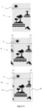
- Figure 3 illustrates an example of the steps of the method according to the invention for the production by welding of tubular bodies with 360° design, having a weld concealed in the continuity of the design.
- the method comprises, for example, the steps described below.
- a first step comprises the definition of the geometrical characteristics of the tubular body to be produced, that is to say, for example, its diameter, its width and its thickness.
- the first step of the method also comprises the creation of the design that is wanted to be shown all around the tubular body.
- the design can be of any type: image(s), drawing(s), plain or shaded colour(s) or a combination thereof, etc.
- an image, called initial image is created, the width and the height of which correspond respectively to the perimeter and the length of the tubular body. The initial image thus perfectly covers the entire surface of the tubular body.
- a second step of the method comprises the creation of an intermediate image by adding a lateral strip on the left of the initial image corresponding to a copy of the right edge of the initial image; or vice versa.
- the intermediate image obtained is wider than the initial image; and, consequently, its width is greater than the perimeter of the tubular body to be manufactured.
- a third step comprises the printing of a succession of intermediate images on a sheet which is then packed on a reel for example.
- the intermediate images are disposed in such a way that the lateral edges of the images are parallel to the direction of unwinding of the sheet.
- the images can be printed in one or more mutually parallel tracks.
- the printed sheet is then wound in order to obtain and pack a single track of intermediate images per reel.
- a fourth step of the method comprises the cutting of a small strip on each lateral side of the intermediate image in order to obtain an image called "final image", the final image comprising a continuity of the decoration between its left edge and its right edge when it is shaped as a tubular body.
- the width of the final image corresponds substantially to the perimeter of the tube to be manufactured.
- the fourth step is performed in a continuous tubular body manufacturing method in which the printed sheet is unwound, trimmed, shaped as a tube and assembled edge-to-edge (for example by welding). A precise adjustment of the width of the final image is performed to obtain a continuity of the design between the left edge and the right edge of the image.
- a fifth step comprises the shaping of the printed sheet in tubular geometry, the printed surface being visible on the outer side of the tube.
- the ends of the printed sheet are disposed edge-to-edge and the diameter of the tubular body is adjusted so that the ends of the sheet are in contact without forming any overlap or shrinkage in the print zone.
- a sixth step comprises the edge-to-edge welding or bonding of the ends of the sheet.
- edges-to-edge welding can comprise an addition of material which reinforces the welded zone. This addition of material can be done in the form of a plastic strip which is welded or bonded onto the ends of the sheet, or by the addition of a bead of extruded material. Preferentially, the addition of the reinforcement is done on the inner face of the tube.
- the tubular body can also comprise a reinforcement on the outer surface of the weld.
- a seventh step comprises the cutting of the tubular body into segments of similar length; the cutting operation being synchronized with the images.
- the final cutting operation makes it possible to obtain tubular bodies decorated over the entire circumference, the weld being concealed in the print.
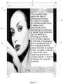
- Figure 4 illustrates an example of initial image 6, of intermediate image 8 and of final image 10 with a design composed of images/drawings, by way of nonlimiting example.
- the initial image 6 has a width 7 which corresponds to the perimeter of the outer surface of the tubular body to be produced.
- the width 7 of the initial image is measured at right angles to the direction of unwinding of the sheet and to the axis of the tubular body.
- the initial image 6 is a virtual image (not printed) which corresponds to the design that is wanted to be obtained on the tubular body.
- Figure 4 illustrates the intermediate image 8 which is constructed by adding, on the left side of the initial image, a strip 13 copying the strip 13 on the right side of the initial image.
- Another intermediate image (not represented) could be obtained by copying, on the right side of the initial image, a strip on the left side of the initial image.
- the intermediate image is characterized by the fact that it comprises two identical lateral strips 13 (one being the copy of the other).
- the lateral strip 13 can comprise images, drawings, plain or shaded colours or a combination thereof, etc., the important factor being that the two lateral edges should be identical.
- the intermediate image 8 obtained therefore has a width 9 which is greater than the perimeter of the tube that is wanted to be manufactured.
- the intermediate image 8 is then printed on the sheet being used to manufacture the tubular body by welding of the ends.
- the decoration is situated on a cylindrical body with 360° design, it is shrewd practice to optimize the primary image to choose the zone in which the weld is situated on the packaging.
- a packaging in tube form having the weld situated at the fold formed by the end weld 5 of the packaging is for example avoided.
- Figure 4 also illustrates the final image 10 that is obtained in the operation of trimming of the edges of the sheet.
- This operation consists notably in taking a small strip from each side of the sheet in order to create a continuity of the decoration between the left edge and the right edge of the sheet.
- This trimming operation is necessary in the manufacturing process in order to eliminate the edges of the sheet which might have been damaged in the storage of the reels, and to adjust, with great accuracy, the width of the sheet prior to the formation of the tubular body.
- Figure 4 illustrates the width 11 of the final image which is adjusted to obtain a continuity of the design between the left edge and the right edge, a continuity which will be produced upon the edge-to-edge welding of the sheet shaped as a tubular body.
- the position of the cut 15 and 16 is located inside the strips 13. The distance between the cut position 15 and the cut position 16 is set during production, which allows for negligible variations of the width 11 throughout the production.
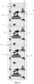
- Figure 5 illustrates one of the advantages of the invention: it makes it possible to overcome variations of lateral positioning of the sheet in the manufacturing method.
- Figure 5 illustrates, in an amplified manner, the principle of the invention which makes it possible to guarantee a continuity of the design between the left edge of the image and the right edge of the image even if the image moves laterally.
- the distance between the cut positions 15 and 16 are constant, so the width of the final image 11 is constant even if the image moves laterally with respect to the cut positions.
- the method according to the invention makes it possible to overcome variations of lateral positions as long as these variations are contained within the lateral strips 13 of width 14 since the strips 13 contain the same image or part of image.
- the invention makes it possible to overcome variations of lateral position of the image with respect to the edges of the sheet of width 12, said sheet being able to include an unprinted lateral part 17.
- the invention makes it possible also to overcome variations of position of the printed sheet with respect to the cut positions 15 and 16.
- the variations illustrated in Figure 5 are illustrative and appear in reality over far greater sheet lengths, potentially corresponding to several hundreds of metres.
- the invention makes it possible to also overcome variations which appear upon change of reel, for example if the design on the second reel is laterally offset with respect to that of the preceding reel.
- Figure 6 illustrates a packaging in tube form 1 obtained by means of a method according to the invention with a continuity of the design over the circumference.
- the tube 1 comprises a tubular body 2 fixed to a tube head 4 comprising an orifice for the extraction of the product contained in the packaging.
- An opening-closing system such as a plug (not represented) is generally associated with the tube head 4.
- the tubular body 2 is closed on the side opposite the head of the tube by virtue of the end weld 5.
- the packaging 1 illustrated in Figure 6 is characterized by the fact that the longitudinal weld 3 of the tubular body 2 is perfectly concealed in the image with a continuity of the design on either side of the longitudinal weld 3.
- Figure 7 illustrates the intermediate image 8 making it possible to produce the packaging illustrated in Figure 6 .
- the intermediate image comprises two identical lateral strips 13 of width 14 situated on the edges of the image.
- the cut positions 15 and 16 of fixed width 11 corresponding to the perimeter of the tube to be produced make it possible to obtain the final image by a trimming operation.
- the cut positions 15, 16 can move laterally within the strip 13 while maintaining a constant separation distance 11.
- the final image obtained after the trimming operation has a continuity of the design between the left edge and the right edge of the image. This continuity of the design is on the tubular body on either side of the longitudinal weld.
- Figure 7 illustrates the intermediate images 8 of width 9 printed on the sheet of width 12.
- the cut positions 15 and 16 define the final images of width 11 obtained after the trimming operation and prior to the shaping as a tubular body.
- the invention makes it possible to overcome small variations of relative lateral positions between the cutting tools 15, 16, the intermediate images and the edges of the sheet.
- means are used to laterally guide the sheet in the method and reduce the amplitude of the variations.
- strip guides controlled by cameras which detect either the edge of the sheet, or the lateral position of the image.
- the preferential method is to regulate the lateral position of the sheet as a function of the position of the image. That makes it possible to limit the waste from the trimming operation.
- the width 14 of the strip 13 must be greater than the amplitude of the variations of the lateral position of the intermediate image 8 with respect to the cut positions 15, 16.
- the width 14 of the strip 13 is for example between 0.5 and 10 mm and preferentially between 1 and 3 mm.
- the width of the intermediate image 13 is for example greater by 1 to 10 mm than the perimeter of the tubular body and preferably by 2 to 4 mm.
- the width of the final image is equal to the width of the initial image allowing for the contractions of the sheet that can take place during the printing operation.
- the perimeter of the tubular body is equal to the width of the final image allowing for the contractions of the sheet during the edge-to-edge welding operation.
- the sheet used in the context of the invention can be a single-layer or multilayer sheet, the thickness of which is between 20 and 500 microns and preferably between 150 and 450 microns.
- the sheet can be based on plastic resin, on biosourced material, on recycled material or even on biodegradable material.
- the printing of the sheet can be done on the surface or be confined in the multilayer structure of the sheet.
- the printing of the sheet is followed by a lamination step to confine the printing.
- the tubular body is manufactured with an edge-to-edge welding method.
- Many configurations described in the prior art can advantageously be associated with the invention.
- the edges of the sheet can be cut at right-angles or at an angle as proposed for example in the patent EP2720849 .
- the edge-to-edge welding can be reinforced by an inner and/or outer strip as proposed for example in the publications EP2007567 , EP2004506 and EP2004389 .
- One alternative consists in reinforcing the edge-to-edge weld with a weld bead as described for example in the publication EP2089213 .
- the sheet can for example be:
- a variant of the invention consists in manufacturing the tubular body by extrusion labelling according to the method described in the publications WO2015/159234 and WO2018/051235 .
- the thin sheet is printed according to the principles of the present invention.
- the sheet is then trimmed according to the invention prior to its shaping in tubular geometry. Then, a tubular body is extruded on the inner face of the sheet shaped in tubular geometry.
- the sheet can therefore be a single-layer film as described in these publications for example, or another equivalent film used in the field of packagings as described in the present application.
Landscapes
- Engineering & Computer Science (AREA)
- Mechanical Engineering (AREA)
- Physics & Mathematics (AREA)
- Thermal Sciences (AREA)
- Making Paper Articles (AREA)
- Tubes (AREA)
Claims (19)
- Verfahren zur Herstellung eines rohrförmigen Körpers (2) für eine Verpackung, wobei das Verfahren die folgenden Schritte umfasst:-) Festlegen der geometrischen Merkmale des herzustellenden rohrförmigen Körpers (2);-) Erzeugen eines Ausgangsbilds (6), das die Oberfläche des zu erzeugenden rohrförmigen Körpers (2) bedeckt, wobei das Ausgangsbild (6) einen rechten Seitenrand und einen linken Seitenrand aufweist;-) Erzeugen eines Zwischenbilds (8) aus dem Ausgangsbild (6) durch Hinzufügen eines seitlichen Streifens (13) zu einem der Ränder des Ausgangsbilds, wobei der seitliche Streifen (13) eine Kopie des anderen der Ränder des Ausgangsbilds umfasst;-) Drucken wenigstens eines Zwischenbilds (8) auf eine Bahn, wobei das Zwischenbild (8) so angeordnet ist, dass die Seitenränder des Bilds parallel zur Abwickelrichtung der Bahn sind;-) Schneiden eines Streifens (15, 16) von jedem Seitenrand des Zwischenbilds, um ein fertiges Bild (10) zu bilden;-) Formen der Bahn zu einem schlauchförmigen Körper (2) und Anordnen Rand an Rand, um Durchgängigkeit des Designs zwischen dem rechten Rand und der linken Rand des Bilds (10) zu erhalten.
- Verfahren nach Anspruch 1, wobei eine Folge von Zwischenbildern (8) auf eine Bahn gedruckt wird.
- Verfahren nach Anspruch 1 oder 2, wobei die Bilder (8) auf mehrere parallele Spuren gedruckt werden und die Bahn aufgerollt wird, um eine einzige Spur von Bildern zu erhalten.
- Verfahren nach einem der vorstehenden Ansprüche, wobei die Eigenschaften des rohrförmigen Körpers (2) der Durchmesser und/oder die Länge und/oder die Dicke sind.
- Verfahren nach einem der vorstehenden Ansprüche, wobei das Ausgangsbild (6) ein Design umfasst, das durch Bild(er), Zeichnung(en), einfache oder schattierte Farbe(en) oder eine Kombination davon gebildet wird.
- Verfahren nach einem der vorstehenden Ansprüche, wobei die Rand-an-Rand-Anordnung durch Schweißen der Bahn oder durch Extrusion eines rohrförmigen Körpers auf der Innenseite der Bahn hergestellt wird.
- Verfahren nach einem der vorstehenden Ansprüche, wobei das Rand-an-Rand-Schweißen Schritte von Erhitzen, Pressen und Kühlen der Enden der Bahn umfasst.
- Verfahren nach einem der vorstehenden Ansprüche, wobei nach dem Schweißvorgang Material zur Verstärkung der Schweißzone zugegeben wird, wobei das Zugeben von Material an der Innenseite des rohrförmigen Körpers (2) und/oder der Außenseite des rohrförmigen Körpers (2) durchgeführt wird.
- Verfahren nach einem der vorstehenden Ansprüche, wobei das Zugeben von Material in der Form eines Kunststoffstreifens durchgeführt wird, der auf die Enden der Bahn geschweißt oder geklebt wird, oder durch Zugeben eines Wulsts von extrudiertem Material.
- Verfahren nach einem der vorstehenden Ansprüche, wobei der rohrförmige Körper (2) in Segmente geschnitten wird, wobei der Vorgang des Schneidens in Segmente mit den Bildern synchronisiert wird.
- Verfahren nach einem der vorstehenden Ansprüche, wobei die Bahn eine ein- oder mehrlagige Folie ist.
- Verfahren nach einem der vorstehenden Ansprüche 1 bis 9, wobei die Bahn ein Laminat ist.
- Verfahren nach einem der vorstehenden Ansprüche, wobei die Bahn auf der Basis von synthetischen Material(ien), Cellulose, Material(ien) mit biologischem Ursprung, recycelten Material (ien), biologisch abbaubaren Material(ien) oder einem Gemisch dieser Materialien ist.
- Rohrförmiger Körper (2), erhalten durch ein Verfahren nach einem der vorstehenden Ansprüche, wobei der rohrförmige Körper (2) eine Bahn mit Seitenrändern umfasst, wobei die Bahn einen Druck umfasst, der ein fertiges Bild (10) bildet, wobei die Seitenränder der Bahn Rand an Rand miteinander verschweißt sind, um Durchgängigkeit des Designs des Bilds (10) zu bilden, so dass die Schweißnaht (3) in dem Druck verborgen ist.
- Rohrförmiger Körper (2) nach dem vorstehenden Anspruch, umfassend ein zugegebenes Material, wobei das Zugeben von Material an der Innenseite des rohrförmigen Körpers (2) und/oder der Außenseite des rohrförmigen Körpers (2) durchgeführt ist.
- Rohrförmiger Körper (2) nach dem vorstehenden Anspruch, wobei das Zugeben von Material in der Form eines Kunststoffstreifens erfolgt ist, der auf die Enden der Bahn geschweißt oder geklebt ist, oder durch Zugeben eines Wulsts von extrudiertem Material.
- Rohrförmiger Körper(2) nach einem der vorstehenden Ansprüche 14 bis 16, wobei die Bahn eine ein- oder mehrlagige Folie ist.
- Rohrförmiger Körper (2) nach einem der vorstehenden Ansprüche 14 bis 16, wobei die Bahn ein Laminat ist.
- Rohrförmiger Körper (2) nach einem der vorstehenden Ansprüche 14 bis 18, wobei die Bahn auf der Basis von synthetischen Material(ien), Cellulose, Material (ien) mit biologischem Ursprung, recycelten Material(ien), biologisch abbaubaren Material(ien) oder einem Gemisch dieser Materialien ist.
Applications Claiming Priority (2)
| Application Number | Priority Date | Filing Date | Title |
|---|---|---|---|
| EP21170375.6A EP4082757A1 (de) | 2021-04-26 | 2021-04-26 | Verpackung, bei der die verschweissung im aufdruck verborgen ist, und entsprechendes herstellungsverfahren |
| PCT/IB2022/053779 WO2022229809A1 (en) | 2021-04-26 | 2022-04-22 | Packaging in which the weld is concealed in the print and manufacturing method |
Publications (2)
| Publication Number | Publication Date |
|---|---|
| EP4330019A1 EP4330019A1 (de) | 2024-03-06 |
| EP4330019B1 true EP4330019B1 (de) | 2025-06-04 |
Family
ID=75825417
Family Applications (2)
| Application Number | Title | Priority Date | Filing Date |
|---|---|---|---|
| EP21170375.6A Withdrawn EP4082757A1 (de) | 2021-04-26 | 2021-04-26 | Verpackung, bei der die verschweissung im aufdruck verborgen ist, und entsprechendes herstellungsverfahren |
| EP22723193.3A Active EP4330019B1 (de) | 2021-04-26 | 2022-04-22 | Verpackung, bei der die verschweissung im aufdruck verborgen ist, und entsprechendes herstellungsverfahren |
Family Applications Before (1)
| Application Number | Title | Priority Date | Filing Date |
|---|---|---|---|
| EP21170375.6A Withdrawn EP4082757A1 (de) | 2021-04-26 | 2021-04-26 | Verpackung, bei der die verschweissung im aufdruck verborgen ist, und entsprechendes herstellungsverfahren |
Country Status (11)
| Country | Link |
|---|---|
| US (1) | US12528631B2 (de) |
| EP (2) | EP4082757A1 (de) |
| JP (1) | JP2024515665A (de) |
| KR (1) | KR20240001143A (de) |
| CN (1) | CN117279770A (de) |
| BR (1) | BR112023017457A2 (de) |
| CA (1) | CA3210436A1 (de) |
| ES (1) | ES3035392T3 (de) |
| MX (1) | MX2023011068A (de) |
| PL (1) | PL4330019T3 (de) |
| WO (1) | WO2022229809A1 (de) |
Family Cites Families (20)
| Publication number | Priority date | Publication date | Assignee | Title |
|---|---|---|---|---|
| SE445031B (sv) | 1984-10-02 | 1986-05-26 | Akerlund & Rausing Ab | Forpackningstub samt forfarande och anordning for tillverkning derav |
| CH686665A5 (de) | 1992-08-26 | 1996-05-31 | Maegerle Karl Lizenz | Verfahren zur Herstellung von Rohrkoerper fuer Verpackungstuben. |
| JPH08324600A (ja) * | 1995-03-27 | 1996-12-10 | Dainippon Printing Co Ltd | ラミネートチューブ |
| RU13025U1 (ru) | 1999-04-08 | 2000-03-20 | Слюсаренко Сергей Валерьевич | Упаковка |
| MX2008012022A (es) | 2006-04-06 | 2008-10-03 | Aisapack Holding Sa | Envase formado a partir de una pelicula soldada a tope. |
| RU2449932C2 (ru) | 2006-04-06 | 2012-05-10 | Айзапак Холдинг С.А. | Гибкая многослойная структура для тюбиков |
| US8916247B2 (en) * | 2006-04-06 | 2014-12-23 | Aisapack Holding S.A. | Thermoplastic tubular packaging body with an embedded strip |
| EP1905570A1 (de) | 2006-09-28 | 2008-04-02 | Aisapack Holding SA | Verfahren und Vorrichtung zum internen Schweissen von Kunststoffrohren |
| KR101632643B1 (ko) | 2008-04-10 | 2016-06-22 | 아이사팩 홀딩 에스에이 | 용접에 의한 튜브 제조방법 |
| EP2444331A1 (de) | 2010-10-22 | 2012-04-25 | Aisapack Holding SA | Flexible, durch Verschweißen hergestellte Verpackung, die Recyclingmaterial oder Material aus erneuerbaren Ressourcen enthält |
| DE102011051110B4 (de) | 2011-06-16 | 2014-04-30 | Packsys Global (Switzerland) Ltd. | Verfahren zum Herstellen von Rohrkörpern für Verpackungstuben |
| DE102011051108A1 (de) | 2011-06-16 | 2012-12-20 | Packsys Global (Switzerland) Ltd. | Verfahren zum Herstellen von Rohrkörpern für Verpackungstuben sowie Verpackungstube mit Rohrkörper |
| EP2674368A1 (de) | 2012-06-15 | 2013-12-18 | Aisapack Holding SA | Stoßgeschweißter rohrförmiger Verpackungskörper |
| WO2015159234A1 (fr) | 2014-04-17 | 2015-10-22 | Aisapack Holding S.A. | Procédé et dispositif d'extrusion et étiquetage d'un tube d'emballage |
| MY178727A (en) | 2014-05-30 | 2020-10-20 | Kyodo Printing Co Ltd | Stacked body for tubes, and tube container |
| EP3292980A1 (de) | 2016-09-13 | 2018-03-14 | Aisapack Holding SA | Verfahren und vorrichtung zum extrudieren und etikettieren eines zylindrischen produkts |
| DE102016118548A1 (de) | 2016-09-29 | 2018-03-29 | Packsys Global Ag | Verfahren und Vorrichtung zum beidseitigen Besäumen eines Flachmaterials im Rahmen der Tubenherstellung |
| US11691791B2 (en) * | 2017-04-05 | 2023-07-04 | Kimpai Lamitube Co., Ltd. | Tubular container with invisible longitudinal overlapped side seam |
| JP7502864B2 (ja) | 2017-05-03 | 2024-06-19 | アイサパック・ホールディング・ソシエテ・アノニム | 多層プラスチックチューブ構造 |
| RU184686U1 (ru) | 2018-01-12 | 2018-11-06 | Открытое Акционерное Общество "Фаберлик" | Ёмкость с укупорочным средством |
-
2021
- 2021-04-26 EP EP21170375.6A patent/EP4082757A1/de not_active Withdrawn
-
2022
- 2022-04-22 ES ES22723193T patent/ES3035392T3/es active Active
- 2022-04-22 MX MX2023011068A patent/MX2023011068A/es unknown
- 2022-04-22 BR BR112023017457A patent/BR112023017457A2/pt unknown
- 2022-04-22 CN CN202280029405.0A patent/CN117279770A/zh active Pending
- 2022-04-22 US US18/556,157 patent/US12528631B2/en active Active
- 2022-04-22 KR KR1020237036489A patent/KR20240001143A/ko active Pending
- 2022-04-22 PL PL22723193.3T patent/PL4330019T3/pl unknown
- 2022-04-22 EP EP22723193.3A patent/EP4330019B1/de active Active
- 2022-04-22 CA CA3210436A patent/CA3210436A1/en active Pending
- 2022-04-22 WO PCT/IB2022/053779 patent/WO2022229809A1/en not_active Ceased
- 2022-04-22 JP JP2023563859A patent/JP2024515665A/ja active Pending
Also Published As
| Publication number | Publication date |
|---|---|
| MX2023011068A (es) | 2023-09-29 |
| ES3035392T3 (en) | 2025-09-02 |
| WO2022229809A1 (en) | 2022-11-03 |
| US20240190632A1 (en) | 2024-06-13 |
| CA3210436A1 (en) | 2022-11-03 |
| US12528631B2 (en) | 2026-01-20 |
| BR112023017457A2 (pt) | 2023-11-07 |
| JP2024515665A (ja) | 2024-04-10 |
| PL4330019T3 (pl) | 2025-08-04 |
| CN117279770A (zh) | 2023-12-22 |
| EP4082757A1 (de) | 2022-11-02 |
| KR20240001143A (ko) | 2024-01-03 |
| EP4330019A1 (de) | 2024-03-06 |
Similar Documents
| Publication | Publication Date | Title |
|---|---|---|
| US11772841B2 (en) | Method for producing a packaging material | |
| JPH02501816A (ja) | 穿孔された内層を有する積層複合材料およびカートンおよびカートンブランクおよびその製品を製造する方法および装置 | |
| KR102293452B1 (ko) | 포장 튜브의 압출 및 라벨링 방법과 장치 | |
| US20040095648A1 (en) | Lenticular sleeves | |
| EP4330019B1 (de) | Verpackung, bei der die verschweissung im aufdruck verborgen ist, und entsprechendes herstellungsverfahren | |
| JPH11320709A (ja) | 折り目を付したパッケ―ジング材料の製造方法 | |
| EP3766700B1 (de) | Verpackungsmaterial und herstellungsverfahren dafür | |
| DK2558298T3 (en) | LAMINATION ROLL, PROCEDURE FOR PROVIDING A PACKAGING LAMINATE AND PACKAGING LAMINATE | |
| JP6095575B2 (ja) | 印刷インクの繰り返しパターンを設けたパッケージ材料の製造方法 | |
| CN113795374B (zh) | 具有360°印刷效果的管用复合膜 | |
| CN110524845B (zh) | 具有协调的模具部件线和纵向接缝的容器 | |
| US20190359383A1 (en) | Labeled container having multiple seams | |
| JPH08324599A (ja) | ラミネートチューブ | |
| JP2007223059A (ja) | 製袋機および製袋方法 | |
| WO2025004795A1 (ja) | ウェブ形成装置および形成方法、および、二重袋の製袋機 | |
| EP3733540A1 (de) | Thermogeformter behälter mit niedriger opazität und längsnaht | |
| AU2015203848B2 (en) | A laminating roller, a method for providing a packaging laminate, and a packaging laminate | |
| WO2003071350A2 (en) | Lenticular sleeves | |
| JP2019523189A (ja) | 磁化部分を含む包装材料、及び材料を磁化する方法 |
Legal Events
| Date | Code | Title | Description |
|---|---|---|---|
| STAA | Information on the status of an ep patent application or granted ep patent |
Free format text: STATUS: UNKNOWN |
|
| STAA | Information on the status of an ep patent application or granted ep patent |
Free format text: STATUS: THE INTERNATIONAL PUBLICATION HAS BEEN MADE |
|
| PUAI | Public reference made under article 153(3) epc to a published international application that has entered the european phase |
Free format text: ORIGINAL CODE: 0009012 |
|
| STAA | Information on the status of an ep patent application or granted ep patent |
Free format text: STATUS: REQUEST FOR EXAMINATION WAS MADE |
|
| 17P | Request for examination filed |
Effective date: 20231001 |
|
| AK | Designated contracting states |
Kind code of ref document: A1 Designated state(s): AL AT BE BG CH CY CZ DE DK EE ES FI FR GB GR HR HU IE IS IT LI LT LU LV MC MK MT NL NO PL PT RO RS SE SI SK SM TR |
|
| DAV | Request for validation of the european patent (deleted) | ||
| DAX | Request for extension of the european patent (deleted) | ||
| STAA | Information on the status of an ep patent application or granted ep patent |
Free format text: STATUS: EXAMINATION IS IN PROGRESS |
|
| 17Q | First examination report despatched |
Effective date: 20241113 |
|
| GRAP | Despatch of communication of intention to grant a patent |
Free format text: ORIGINAL CODE: EPIDOSNIGR1 |
|
| STAA | Information on the status of an ep patent application or granted ep patent |
Free format text: STATUS: GRANT OF PATENT IS INTENDED |
|
| INTG | Intention to grant announced |
Effective date: 20250123 |
|
| GRAS | Grant fee paid |
Free format text: ORIGINAL CODE: EPIDOSNIGR3 |
|
| GRAA | (expected) grant |
Free format text: ORIGINAL CODE: 0009210 |
|
| STAA | Information on the status of an ep patent application or granted ep patent |
Free format text: STATUS: THE PATENT HAS BEEN GRANTED |
|
| AK | Designated contracting states |
Kind code of ref document: B1 Designated state(s): AL AT BE BG CH CY CZ DE DK EE ES FI FR GB GR HR HU IE IS IT LI LT LU LV MC MK MT NL NO PL PT RO RS SE SI SK SM TR |
|
| REG | Reference to a national code |
Ref country code: GB Ref legal event code: FG4D |
|
| REG | Reference to a national code |
Ref country code: CH Ref legal event code: EP |
|
| REG | Reference to a national code |
Ref country code: DE Ref legal event code: R096 Ref document number: 602022015525 Country of ref document: DE |
|
| REG | Reference to a national code |
Ref country code: IE Ref legal event code: FG4D |
|
| REG | Reference to a national code |
Ref country code: SE Ref legal event code: TRGR |
|
| REG | Reference to a national code |
Ref country code: ES Ref legal event code: FG2A Ref document number: 3035392 Country of ref document: ES Kind code of ref document: T3 Effective date: 20250902 |
|
| REG | Reference to a national code |
Ref country code: SK Ref legal event code: T3 Ref document number: E 46728 Country of ref document: SK |
|
| REG | Reference to a national code |
Ref country code: NL Ref legal event code: MP Effective date: 20250604 |
|
| PG25 | Lapsed in a contracting state [announced via postgrant information from national office to epo] |
Ref country code: FI Free format text: LAPSE BECAUSE OF FAILURE TO SUBMIT A TRANSLATION OF THE DESCRIPTION OR TO PAY THE FEE WITHIN THE PRESCRIBED TIME-LIMIT Effective date: 20250604 |
|
| REG | Reference to a national code |
Ref country code: LT Ref legal event code: MG9D |
|
| PG25 | Lapsed in a contracting state [announced via postgrant information from national office to epo] |
Ref country code: GR Free format text: LAPSE BECAUSE OF FAILURE TO SUBMIT A TRANSLATION OF THE DESCRIPTION OR TO PAY THE FEE WITHIN THE PRESCRIBED TIME-LIMIT Effective date: 20250905 Ref country code: NO Free format text: LAPSE BECAUSE OF FAILURE TO SUBMIT A TRANSLATION OF THE DESCRIPTION OR TO PAY THE FEE WITHIN THE PRESCRIBED TIME-LIMIT Effective date: 20250904 |
|
| PG25 | Lapsed in a contracting state [announced via postgrant information from national office to epo] |
Ref country code: HR Free format text: LAPSE BECAUSE OF FAILURE TO SUBMIT A TRANSLATION OF THE DESCRIPTION OR TO PAY THE FEE WITHIN THE PRESCRIBED TIME-LIMIT Effective date: 20250604 |
|
| PG25 | Lapsed in a contracting state [announced via postgrant information from national office to epo] |
Ref country code: RS Free format text: LAPSE BECAUSE OF FAILURE TO SUBMIT A TRANSLATION OF THE DESCRIPTION OR TO PAY THE FEE WITHIN THE PRESCRIBED TIME-LIMIT Effective date: 20250904 |
|
| PG25 | Lapsed in a contracting state [announced via postgrant information from national office to epo] |
Ref country code: LV Free format text: LAPSE BECAUSE OF FAILURE TO SUBMIT A TRANSLATION OF THE DESCRIPTION OR TO PAY THE FEE WITHIN THE PRESCRIBED TIME-LIMIT Effective date: 20250604 |
|
| PG25 | Lapsed in a contracting state [announced via postgrant information from national office to epo] |
Ref country code: NL Free format text: LAPSE BECAUSE OF FAILURE TO SUBMIT A TRANSLATION OF THE DESCRIPTION OR TO PAY THE FEE WITHIN THE PRESCRIBED TIME-LIMIT Effective date: 20250604 |
|
| PG25 | Lapsed in a contracting state [announced via postgrant information from national office to epo] |
Ref country code: PT Free format text: LAPSE BECAUSE OF FAILURE TO SUBMIT A TRANSLATION OF THE DESCRIPTION OR TO PAY THE FEE WITHIN THE PRESCRIBED TIME-LIMIT Effective date: 20251006 |
|
| PG25 | Lapsed in a contracting state [announced via postgrant information from national office to epo] |
Ref country code: IS Free format text: LAPSE BECAUSE OF FAILURE TO SUBMIT A TRANSLATION OF THE DESCRIPTION OR TO PAY THE FEE WITHIN THE PRESCRIBED TIME-LIMIT Effective date: 20251004 |
|
| PG25 | Lapsed in a contracting state [announced via postgrant information from national office to epo] |
Ref country code: SM Free format text: LAPSE BECAUSE OF FAILURE TO SUBMIT A TRANSLATION OF THE DESCRIPTION OR TO PAY THE FEE WITHIN THE PRESCRIBED TIME-LIMIT Effective date: 20250604 |
|
| PG25 | Lapsed in a contracting state [announced via postgrant information from national office to epo] |
Ref country code: CZ Free format text: LAPSE BECAUSE OF FAILURE TO SUBMIT A TRANSLATION OF THE DESCRIPTION OR TO PAY THE FEE WITHIN THE PRESCRIBED TIME-LIMIT Effective date: 20250604 |
|
| PG25 | Lapsed in a contracting state [announced via postgrant information from national office to epo] |
Ref country code: EE Free format text: LAPSE BECAUSE OF FAILURE TO SUBMIT A TRANSLATION OF THE DESCRIPTION OR TO PAY THE FEE WITHIN THE PRESCRIBED TIME-LIMIT Effective date: 20250604 |
|
| PLBI | Opposition filed |
Free format text: ORIGINAL CODE: 0009260 |
|
| REG | Reference to a national code |
Ref country code: CH Ref legal event code: L10 Free format text: ST27 STATUS EVENT CODE: U-0-0-L10-L00 (AS PROVIDED BY THE NATIONAL OFFICE) Effective date: 20260204 |