EP4330014B1 - Extrusion für den 3d-druck - Google Patents
Extrusion für den 3d-druck Download PDFInfo
- Publication number
- EP4330014B1 EP4330014B1 EP22726123.7A EP22726123A EP4330014B1 EP 4330014 B1 EP4330014 B1 EP 4330014B1 EP 22726123 A EP22726123 A EP 22726123A EP 4330014 B1 EP4330014 B1 EP 4330014B1
- Authority
- EP
- European Patent Office
- Prior art keywords
- reservoir
- channel
- extruder
- extrusion
- heater
- Prior art date
- Legal status (The legal status is an assumption and is not a legal conclusion. Google has not performed a legal analysis and makes no representation as to the accuracy of the status listed.)
- Active
Links
Images


Classifications
-
- B—PERFORMING OPERATIONS; TRANSPORTING
- B29—WORKING OF PLASTICS; WORKING OF SUBSTANCES IN A PLASTIC STATE IN GENERAL
- B29C—SHAPING OR JOINING OF PLASTICS; SHAPING OF MATERIAL IN A PLASTIC STATE, NOT OTHERWISE PROVIDED FOR; AFTER-TREATMENT OF THE SHAPED PRODUCTS, e.g. REPAIRING
- B29C64/00—Additive manufacturing, i.e. manufacturing of three-dimensional [3D] objects by additive deposition, additive agglomeration or additive layering, e.g. by 3D printing, stereolithography or selective laser sintering
- B29C64/30—Auxiliary operations or equipment
- B29C64/307—Handling of material to be used in additive manufacturing
- B29C64/321—Feeding
-
- B—PERFORMING OPERATIONS; TRANSPORTING
- B22—CASTING; POWDER METALLURGY
- B22F—WORKING METALLIC POWDER; MANUFACTURE OF ARTICLES FROM METALLIC POWDER; MAKING METALLIC POWDER; APPARATUS OR DEVICES SPECIALLY ADAPTED FOR METALLIC POWDER
- B22F10/00—Additive manufacturing of workpieces or articles from metallic powder
- B22F10/10—Formation of a green body
- B22F10/18—Formation of a green body by mixing binder with metal in filament form, e.g. fused filament fabrication [FFF]
-
- B—PERFORMING OPERATIONS; TRANSPORTING
- B22—CASTING; POWDER METALLURGY
- B22F—WORKING METALLIC POWDER; MANUFACTURE OF ARTICLES FROM METALLIC POWDER; MAKING METALLIC POWDER; APPARATUS OR DEVICES SPECIALLY ADAPTED FOR METALLIC POWDER
- B22F10/00—Additive manufacturing of workpieces or articles from metallic powder
- B22F10/80—Data acquisition or data processing
- B22F10/85—Data acquisition or data processing for controlling or regulating additive manufacturing processes
-
- B—PERFORMING OPERATIONS; TRANSPORTING
- B22—CASTING; POWDER METALLURGY
- B22F—WORKING METALLIC POWDER; MANUFACTURE OF ARTICLES FROM METALLIC POWDER; MAKING METALLIC POWDER; APPARATUS OR DEVICES SPECIALLY ADAPTED FOR METALLIC POWDER
- B22F12/00—Apparatus or devices specially adapted for additive manufacturing; Auxiliary means for additive manufacturing; Combinations of additive manufacturing apparatus or devices with other processing apparatus or devices
- B22F12/50—Means for feeding of material, e.g. heads
- B22F12/53—Nozzles
-
- B—PERFORMING OPERATIONS; TRANSPORTING
- B29—WORKING OF PLASTICS; WORKING OF SUBSTANCES IN A PLASTIC STATE IN GENERAL
- B29C—SHAPING OR JOINING OF PLASTICS; SHAPING OF MATERIAL IN A PLASTIC STATE, NOT OTHERWISE PROVIDED FOR; AFTER-TREATMENT OF THE SHAPED PRODUCTS, e.g. REPAIRING
- B29C48/00—Extrusion moulding, i.e. expressing the moulding material through a die or nozzle which imparts the desired form; Apparatus therefor
- B29C48/02—Small extruding apparatus, e.g. handheld, toy or laboratory extruders
-
- B—PERFORMING OPERATIONS; TRANSPORTING
- B29—WORKING OF PLASTICS; WORKING OF SUBSTANCES IN A PLASTIC STATE IN GENERAL
- B29C—SHAPING OR JOINING OF PLASTICS; SHAPING OF MATERIAL IN A PLASTIC STATE, NOT OTHERWISE PROVIDED FOR; AFTER-TREATMENT OF THE SHAPED PRODUCTS, e.g. REPAIRING
- B29C48/00—Extrusion moulding, i.e. expressing the moulding material through a die or nozzle which imparts the desired form; Apparatus therefor
- B29C48/03—Extrusion moulding, i.e. expressing the moulding material through a die or nozzle which imparts the desired form; Apparatus therefor characterised by the shape of the extruded material at extrusion
- B29C48/05—Filamentary, e.g. strands
-
- B—PERFORMING OPERATIONS; TRANSPORTING
- B29—WORKING OF PLASTICS; WORKING OF SUBSTANCES IN A PLASTIC STATE IN GENERAL
- B29C—SHAPING OR JOINING OF PLASTICS; SHAPING OF MATERIAL IN A PLASTIC STATE, NOT OTHERWISE PROVIDED FOR; AFTER-TREATMENT OF THE SHAPED PRODUCTS, e.g. REPAIRING
- B29C48/00—Extrusion moulding, i.e. expressing the moulding material through a die or nozzle which imparts the desired form; Apparatus therefor
- B29C48/25—Component parts, details or accessories; Auxiliary operations
- B29C48/266—Means for allowing relative movements between the apparatus parts, e.g. for twisting the extruded article or for moving the die along a surface to be coated
-
- B—PERFORMING OPERATIONS; TRANSPORTING
- B29—WORKING OF PLASTICS; WORKING OF SUBSTANCES IN A PLASTIC STATE IN GENERAL
- B29C—SHAPING OR JOINING OF PLASTICS; SHAPING OF MATERIAL IN A PLASTIC STATE, NOT OTHERWISE PROVIDED FOR; AFTER-TREATMENT OF THE SHAPED PRODUCTS, e.g. REPAIRING
- B29C48/00—Extrusion moulding, i.e. expressing the moulding material through a die or nozzle which imparts the desired form; Apparatus therefor
- B29C48/25—Component parts, details or accessories; Auxiliary operations
- B29C48/78—Thermal treatment of the extrusion moulding material or of preformed parts or layers, e.g. by heating or cooling
- B29C48/80—Thermal treatment of the extrusion moulding material or of preformed parts or layers, e.g. by heating or cooling at the plasticising zone, e.g. by heating cylinders
- B29C48/83—Heating or cooling the cylinders
-
- B—PERFORMING OPERATIONS; TRANSPORTING
- B29—WORKING OF PLASTICS; WORKING OF SUBSTANCES IN A PLASTIC STATE IN GENERAL
- B29C—SHAPING OR JOINING OF PLASTICS; SHAPING OF MATERIAL IN A PLASTIC STATE, NOT OTHERWISE PROVIDED FOR; AFTER-TREATMENT OF THE SHAPED PRODUCTS, e.g. REPAIRING
- B29C48/00—Extrusion moulding, i.e. expressing the moulding material through a die or nozzle which imparts the desired form; Apparatus therefor
- B29C48/25—Component parts, details or accessories; Auxiliary operations
- B29C48/78—Thermal treatment of the extrusion moulding material or of preformed parts or layers, e.g. by heating or cooling
- B29C48/86—Thermal treatment of the extrusion moulding material or of preformed parts or layers, e.g. by heating or cooling at the nozzle zone
- B29C48/872—Thermal treatment of the extrusion moulding material or of preformed parts or layers, e.g. by heating or cooling at the nozzle zone characterised by differential heating or cooling
- B29C48/873—Thermal treatment of the extrusion moulding material or of preformed parts or layers, e.g. by heating or cooling at the nozzle zone characterised by differential heating or cooling in the direction of the stream of the material
-
- B—PERFORMING OPERATIONS; TRANSPORTING
- B29—WORKING OF PLASTICS; WORKING OF SUBSTANCES IN A PLASTIC STATE IN GENERAL
- B29C—SHAPING OR JOINING OF PLASTICS; SHAPING OF MATERIAL IN A PLASTIC STATE, NOT OTHERWISE PROVIDED FOR; AFTER-TREATMENT OF THE SHAPED PRODUCTS, e.g. REPAIRING
- B29C64/00—Additive manufacturing, i.e. manufacturing of three-dimensional [3D] objects by additive deposition, additive agglomeration or additive layering, e.g. by 3D printing, stereolithography or selective laser sintering
- B29C64/10—Processes of additive manufacturing
- B29C64/106—Processes of additive manufacturing using only liquids or viscous materials, e.g. depositing a continuous bead of viscous material
- B29C64/118—Processes of additive manufacturing using only liquids or viscous materials, e.g. depositing a continuous bead of viscous material using filamentary material being melted, e.g. fused deposition modelling [FDM]
-
- B—PERFORMING OPERATIONS; TRANSPORTING
- B29—WORKING OF PLASTICS; WORKING OF SUBSTANCES IN A PLASTIC STATE IN GENERAL
- B29C—SHAPING OR JOINING OF PLASTICS; SHAPING OF MATERIAL IN A PLASTIC STATE, NOT OTHERWISE PROVIDED FOR; AFTER-TREATMENT OF THE SHAPED PRODUCTS, e.g. REPAIRING
- B29C64/00—Additive manufacturing, i.e. manufacturing of three-dimensional [3D] objects by additive deposition, additive agglomeration or additive layering, e.g. by 3D printing, stereolithography or selective laser sintering
- B29C64/20—Apparatus for additive manufacturing; Details thereof or accessories therefor
- B29C64/205—Means for applying layers
- B29C64/209—Heads; Nozzles
-
- B—PERFORMING OPERATIONS; TRANSPORTING
- B29—WORKING OF PLASTICS; WORKING OF SUBSTANCES IN A PLASTIC STATE IN GENERAL
- B29C—SHAPING OR JOINING OF PLASTICS; SHAPING OF MATERIAL IN A PLASTIC STATE, NOT OTHERWISE PROVIDED FOR; AFTER-TREATMENT OF THE SHAPED PRODUCTS, e.g. REPAIRING
- B29C64/00—Additive manufacturing, i.e. manufacturing of three-dimensional [3D] objects by additive deposition, additive agglomeration or additive layering, e.g. by 3D printing, stereolithography or selective laser sintering
- B29C64/20—Apparatus for additive manufacturing; Details thereof or accessories therefor
- B29C64/245—Platforms or substrates
-
- B—PERFORMING OPERATIONS; TRANSPORTING
- B29—WORKING OF PLASTICS; WORKING OF SUBSTANCES IN A PLASTIC STATE IN GENERAL
- B29C—SHAPING OR JOINING OF PLASTICS; SHAPING OF MATERIAL IN A PLASTIC STATE, NOT OTHERWISE PROVIDED FOR; AFTER-TREATMENT OF THE SHAPED PRODUCTS, e.g. REPAIRING
- B29C64/00—Additive manufacturing, i.e. manufacturing of three-dimensional [3D] objects by additive deposition, additive agglomeration or additive layering, e.g. by 3D printing, stereolithography or selective laser sintering
- B29C64/20—Apparatus for additive manufacturing; Details thereof or accessories therefor
- B29C64/295—Heating elements
-
- B—PERFORMING OPERATIONS; TRANSPORTING
- B29—WORKING OF PLASTICS; WORKING OF SUBSTANCES IN A PLASTIC STATE IN GENERAL
- B29C—SHAPING OR JOINING OF PLASTICS; SHAPING OF MATERIAL IN A PLASTIC STATE, NOT OTHERWISE PROVIDED FOR; AFTER-TREATMENT OF THE SHAPED PRODUCTS, e.g. REPAIRING
- B29C64/00—Additive manufacturing, i.e. manufacturing of three-dimensional [3D] objects by additive deposition, additive agglomeration or additive layering, e.g. by 3D printing, stereolithography or selective laser sintering
- B29C64/30—Auxiliary operations or equipment
- B29C64/386—Data acquisition or data processing for additive manufacturing
- B29C64/393—Data acquisition or data processing for additive manufacturing for controlling or regulating additive manufacturing processes
-
- B—PERFORMING OPERATIONS; TRANSPORTING
- B33—ADDITIVE MANUFACTURING TECHNOLOGY
- B33Y—ADDITIVE MANUFACTURING, i.e. MANUFACTURING OF THREE-DIMENSIONAL [3D] OBJECTS BY ADDITIVE DEPOSITION, ADDITIVE AGGLOMERATION OR ADDITIVE LAYERING, e.g. BY 3D PRINTING, STEREOLITHOGRAPHY OR SELECTIVE LASER SINTERING
- B33Y40/00—Auxiliary operations or equipment, e.g. for material handling
-
- B—PERFORMING OPERATIONS; TRANSPORTING
- B22—CASTING; POWDER METALLURGY
- B22F—WORKING METALLIC POWDER; MANUFACTURE OF ARTICLES FROM METALLIC POWDER; MAKING METALLIC POWDER; APPARATUS OR DEVICES SPECIALLY ADAPTED FOR METALLIC POWDER
- B22F2203/00—Controlling
- B22F2203/11—Controlling temperature, temperature profile
-
- B—PERFORMING OPERATIONS; TRANSPORTING
- B22—CASTING; POWDER METALLURGY
- B22F—WORKING METALLIC POWDER; MANUFACTURE OF ARTICLES FROM METALLIC POWDER; MAKING METALLIC POWDER; APPARATUS OR DEVICES SPECIALLY ADAPTED FOR METALLIC POWDER
- B22F2999/00—Aspects linked to processes or compositions used in powder metallurgy
-
- B—PERFORMING OPERATIONS; TRANSPORTING
- B29—WORKING OF PLASTICS; WORKING OF SUBSTANCES IN A PLASTIC STATE IN GENERAL
- B29C—SHAPING OR JOINING OF PLASTICS; SHAPING OF MATERIAL IN A PLASTIC STATE, NOT OTHERWISE PROVIDED FOR; AFTER-TREATMENT OF THE SHAPED PRODUCTS, e.g. REPAIRING
- B29C2948/00—Indexing scheme relating to extrusion moulding
- B29C2948/92—Measuring, controlling or regulating
- B29C2948/92504—Controlled parameter
- B29C2948/92704—Temperature
-
- B—PERFORMING OPERATIONS; TRANSPORTING
- B29—WORKING OF PLASTICS; WORKING OF SUBSTANCES IN A PLASTIC STATE IN GENERAL
- B29C—SHAPING OR JOINING OF PLASTICS; SHAPING OF MATERIAL IN A PLASTIC STATE, NOT OTHERWISE PROVIDED FOR; AFTER-TREATMENT OF THE SHAPED PRODUCTS, e.g. REPAIRING
- B29C2948/00—Indexing scheme relating to extrusion moulding
- B29C2948/92—Measuring, controlling or regulating
- B29C2948/92819—Location or phase of control
- B29C2948/92857—Extrusion unit
- B29C2948/92876—Feeding, melting, plasticising or pumping zones, e.g. the melt itself
-
- B—PERFORMING OPERATIONS; TRANSPORTING
- B29—WORKING OF PLASTICS; WORKING OF SUBSTANCES IN A PLASTIC STATE IN GENERAL
- B29C—SHAPING OR JOINING OF PLASTICS; SHAPING OF MATERIAL IN A PLASTIC STATE, NOT OTHERWISE PROVIDED FOR; AFTER-TREATMENT OF THE SHAPED PRODUCTS, e.g. REPAIRING
- B29C2948/00—Indexing scheme relating to extrusion moulding
- B29C2948/92—Measuring, controlling or regulating
- B29C2948/92819—Location or phase of control
- B29C2948/92857—Extrusion unit
- B29C2948/92904—Die; Nozzle zone
-
- B—PERFORMING OPERATIONS; TRANSPORTING
- B33—ADDITIVE MANUFACTURING TECHNOLOGY
- B33Y—ADDITIVE MANUFACTURING, i.e. MANUFACTURING OF THREE-DIMENSIONAL [3D] OBJECTS BY ADDITIVE DEPOSITION, ADDITIVE AGGLOMERATION OR ADDITIVE LAYERING, e.g. BY 3D PRINTING, STEREOLITHOGRAPHY OR SELECTIVE LASER SINTERING
- B33Y10/00—Processes of additive manufacturing
-
- B—PERFORMING OPERATIONS; TRANSPORTING
- B33—ADDITIVE MANUFACTURING TECHNOLOGY
- B33Y—ADDITIVE MANUFACTURING, i.e. MANUFACTURING OF THREE-DIMENSIONAL [3D] OBJECTS BY ADDITIVE DEPOSITION, ADDITIVE AGGLOMERATION OR ADDITIVE LAYERING, e.g. BY 3D PRINTING, STEREOLITHOGRAPHY OR SELECTIVE LASER SINTERING
- B33Y30/00—Apparatus for additive manufacturing; Details thereof or accessories therefor
-
- B—PERFORMING OPERATIONS; TRANSPORTING
- B33—ADDITIVE MANUFACTURING TECHNOLOGY
- B33Y—ADDITIVE MANUFACTURING, i.e. MANUFACTURING OF THREE-DIMENSIONAL [3D] OBJECTS BY ADDITIVE DEPOSITION, ADDITIVE AGGLOMERATION OR ADDITIVE LAYERING, e.g. BY 3D PRINTING, STEREOLITHOGRAPHY OR SELECTIVE LASER SINTERING
- B33Y50/00—Data acquisition or data processing for additive manufacturing
- B33Y50/02—Data acquisition or data processing for additive manufacturing for controlling or regulating additive manufacturing processes
Definitions
- the invention relates to the field of 3D printing. More specifically it relates to extrusion methods and extruders for continuous extrusion.
- 3D printing and other additive manufacturing techniques allow a great deal of freedom of design and prototyping.
- the leap from the design process and the manufacture can be reduced, because a product can be produced and tested, right after the design, at lower cost than if an entire industrial manufacturing process has to be set up for just the testing phase.
- Well established techniques include wire-based 3D printing, such as fused filament fabrication (FFF). These techniques include providing, usually by extrusion, a continuous wire which is deposited and attached to a plate or to other already deposited wires, forming a 3D object.
- the materials are typically polymers and metals or a mixture thereof, and the attachment can be done with polymers or ceramic acting as adhesive, sometimes followed by sintering or curing, or by thermal fusion between the wires.
- extrusion usually requires heating the material so it can fuse upon deposition.
- Extrusion of polymer is slow due to their viscosity, thermal conductivity, etc. The range of temperatures available to compensate for these effects is limited due to chemical decomposition.
- extrusion of metal requires melting it, and liquid metal is difficult to extrude in a controlled way. Viscosity of molten metal is comparable to water, so introducing fed material on a liquid pool as done in FFF displaces a volume of liquid against the direction of the fed material, with clogging as a result. Molten metal dripping and oozing from the extruder becomes also an issue due to the material properties, it cannot be tackled in the same way as done for polymers (e.g.
- Document US 2016/354977 A1 discloses a 3D printing system based on FFF which improves heating control, by adding non-contact heat sources such as lasers around the nozzle. These enlarge the melt zone, allowing faster printing.
- non-contact heat sources such as lasers around the nozzle.
- the viscosity of the molten material can cause oozing, so an active cooler may be required.
- the active cooler can activated and non-contact heat sources deactivated. This requires a large amount of energy for the heating sources and for the cooler, since the cooling speed needs to be high enough so as to solidify low viscosity molten metal fast enough to prevent oozing.
- a metal wire can be done by mixture of powder metal with binder such as resin and extruding this mixture.
- binder such as resin
- the technique requires an after-treatment to remove the binder and ensure the integrity and adhesion of the layers of deposited material, which creates a further step in the process and brings issues such as stresses, shrinkage or even cracking, limiting the design complexity and flexibility.
- Extrusion force is highly influenced by flow rate, which is very sensitive to friction, oxidation, etc. Reliable and consistent extrusion is difficult to obtain, even by pressure-driven extrusion.
- Document US2018345573A1 discloses an additive manufacturing system requiring a source of pressurized gas to overcome the resistance of the extrusion tube to the passage of metal to be extruded
- FFF Fused Filament Fabrication
- the present invention provides an extruder for 3D printing, comprising an outlet for providing extruded material, and a feedstock inlet piece for receiving material into the extruder.
- the feedstock inlet piece is an extruder part or piece including cooling means for cooling said material entering the extruder.
- the feedstock inlet piece includes the inlet to allow entry of material to the extruder.
- a reservoir is included for melting material and for keeping molten material, having a reservoir width.
- the reservoir is connected to the outlet.
- a channel with a channel width is arranged for connecting the feedstock inlet piece with the reservoir and for introducing the material into the reservoir.
- the channel width is lower than the reservoir width.
- the extruder further comprises at least one heater for melting material in the reservoir, and a controller for controlling the temperature gradient of the material through the channel.
- the controller is configured to maintain the level of molten material at least at the junction between the reservoir and the channel or along the channel during extrusion, for providing extrusion by the material introduced through the feedstock inlet piece and pushing on the molten material in the reservoir.
- a mushy region of material being in transition between the liquid state and solid state is present in the channel, closer to the reservoir than to the feedstock inlet piece. This is controlled by the temperature gradient, which in turn is controlled by controlling heating/cooling and/or feeding parameters with a controller, e.g. connected to a CPU.
- the mushy region and the feedstock material acts as a plunger.
- an extruder can be provided with controllable extrusion speed which depends on the feedrate, as a mushy zone present in the channel out of the reservoir, or the molten material filling the reservoir, seals the reservoir.
- the sealing also reduces the amount of liquid going upwards.
- the presence of the wider reservoir reduces the friction between the wire and the walls of the extruder, so the feeding force can be reduced, thus reducing the chances of bending or buckling in case of wire feeding.
- oozing and dripping, even in metal extrusion can be reduced or removed thanks to the sealing.
- the controller is configured to control the heater.
- the cooling means including an active cooler allowing control of the cooling rate.
- the controller is configured to control the active cooler for controlling the cooling rate of the material upon entry in the extruder.
- the extruder further comprises a material feeder for feeding material into the feedstock inlet piece which can be controlled by the controller, and the controller is further configured to control the material feeder to control the feedrate.
- the material feeder is a wire feeder for feeding wire.
- the extruder further comprises a load cell between the wire feeder and feedstock inlet piece to measure the extrusion force on the wire.
- the heater includes a first heater for melting material in a first reservoir part of the reservoir close to the channel.
- the heater further comprises a second heater close to the connection of the reservoir to the outlet, for maintaining molten material in a second reservoir part of the reservoir close to the outlet at the same temperature as the material in the first reservoir part or at higher temperature.
- first reservoir can be used to provide a piston sealing and the second reservoir can be used to provide high control of the extrusion temperature.
- the first heater is distanced from the second heater by a thermal break separating the reservoir in a first reservoir part close to the channel and a second reservoir part close to the outlet. It is an advantage that the temperature in both parts can be accurately controlled independently, as there is less heat loss from one part to the other, specially when keeping them at different temperatures.
- the thermal break provides a further channel being adapted to thermally insulate the first part from the second part of the reservoir. It is an advantage of embodiments of the present invention that high temperature control of extruded material is provided and guaranteed.
- the outlet comprises a further heater for controlling the temperature of the extruded material at the outlet.
- heat loss for example heat extraction by an extruder nozzle at the outlet
- process control can be improved as the heating response is fast, as the thermal mass of the extruded material is small.
- an insulating piece including at least a portion of the channel is included, to thermally insulate the feedstock inlet piece from the reservoir. It is an advantage of embodiments that it allows a mushy zone to be formed along the channel but close to the reservoir to avoid clogging, outside the reservoir and between the heater and cooling means. It is a further advantage that a more controllable temperature and steep gradient can be provided between the cooling means of the feedstock inlet piece and the heaters, maximizing the efficiency (because to create a steep temp gradient it is required to intensively cool one side and heat the other side.
- electrodes are present and configured to apply a voltage between the extruder and a buildplate of a 3D printer. It is an advantage of embodiments that the adhesion can be improved by locally heating the buildplate.
- the outlet comprises an extrusion nozzle, optionally a replaceable nozzle.
- a method for extruding material comprises
- extrusion speed can be controlled, by controlling feedrate, because the mushy region or zone present in the channel, out of the reservoir, seals the extruder thus allowing higher feedrates without liquid going upwards. It is a further advantage that oozing and dripping in metal extrusion can be reduced or removed thanks to the sealing, even for molten materials with low viscosity. It is a further advantage that the reduced friction along the extruder reduces bending or buckling in case of wire feeding, because the friction occurs mostly along the channel and it is relieved by the reservoir being wider than the channel.
- the method comprises controlling the feedrate of material. Additionally or alternatively, cooling the material comprises controlling the cooling rate. It is an advantage of embodiments of the present invention that stable and controllable extrusion can be obtained by improving control of the temperature gradient, thus improving the localization of the formation of the mushy zone with no need of reducing the temperature of the material in the reservoir. In wire feeding, chances of bending are further reduced as the presence of the reservoir reduces wire friction with the extruder. It is a further advantage that stable and controllable extrusion can be obtained for different feedrates.
- the method is a method for extruding aluminum, an aluminum alloy or copper.
- muscle zone reference is made to the region of a solid where melting takes place, between its liquid phase and its solid phase.
- 'solid' it is understood a material in its solid phase, which may be in the form of powder, pellets, wire, etc. at a condition (temperature) falling within the solid region of its phase diagram.
- Suitable materials for extrusion include metals, alloys, polymer, etc.
- Polymeric materials also require heating to soften them to a viscous state easily extrudable state, which can be considered a molten state and which starts at the glass transition temperature in case of polymers, and the transition region between these unmolten and molten states may also be called 'mushy zone' for simplicity.
- the present invention relates to 3D printing methods like Fused Filament Fabrication (FFF), in particular to wire-based 3D printing in which a continuously extruded wire is formed and deposited.
- FFF Fused Filament Fabrication
- Extrusion volume and adhesion of the wire to the underlying material are critical parameters. For good adhesion, one of the requirements is having sufficient temperature of the wire .
- Softening and melting of the material for extrusion require high temperatures (e.g. temperatures above melting temperature of the material) but molten material is difficult to handle, both polymers and metals typically used in 3D printing mainly due to the low viscosity and high thermal conductivity.
- Softened (molten) material is forced through an outlet shaped so a wire can be formed, usually a nozzle. This force has to be provided while at the same time keeping the material molten.
- Pressure driven extrusion systems are dependent on forces such as friction, wear, oxidation.... These forces are unstable and can easily vary. Using a high-pressure system may allow higher friction and better control, but in some cases it increases the complexity of the system.
- volumetric extrusion was introduced, where ideally the volume of material introduced in the extruder is the same as the volume of extruded material, and it is independent of the required force.
- Volumetric extrusion can be achieved by the pushing/displacement of feeding material, e.g. a fed wire or extrusion screw for granulates, very similar to polymer printing (FFF technology).
- feeding material e.g. a fed wire or extrusion screw for granulates
- FFF technology polymer printing
- the low conductivity of polymers reduces heat transfer from the heater to the polymer, compared to the case of metals.
- the maximum usable temperature of polymers is limited to prevent decomposition.
- the present invention provides an extruder and a method of extrusion of materials which enter the device in a solid state and exit in a molten state, for different materials with a wide range of viscosity including polymers (>100mPa.s) and metals ( ⁇ 100mPa.s), and for a wide range of deposition speeds.
- the present invention allows, for a standard nozzle hole (up to ⁇ 1mm), a deposition rate close to 1l/h or even larger.
- a higher nozzle diameter e.g. 5 mm
- higher deposition rates up to 15l/h, depending on layer thicknesses and heating power.
- the invention provides a volume, or 'reservoir', in the extruder which is filled with molten material.
- a channel is used to feed material to this reservoir, and an outlet, connected to the reservoir, provides extruded material.
- the extruder is configured so that material does not flow upwards the channel.
- the extruder is designed so the material being fed does not heat up to the melting temperatures at the inlet of the extruder, while the material in the reservoir is heated up so molten material fills the reservoir.
- the reservoir is wider than the channel, so upflow is limited by increasing resistance due to the bottleneck between the reservoir and channel.
- extrusion rate can be controlled by the feeding of the material, for example by changing the rate at which material is fed or feedrate.
- the amount of material flowing upwards is reduced or removed, not only by the configuration of the channel and reservoir, but also by controlling the temperature gradient, ensuring that the position of the mushy zone is close to the reservoir.
- the accurate position at which material is 'mushy' is a result of the design, based on the used materials, power consumption, characteristics of the extruded material, feedrate and operating temperatures, for example.
- a temperature gradient through the fed material passing through the channel before the reservoir is required so there is molten material at least in the reservoir, optionally in the reservoir and part of the channel so there is a mushy zone along the channel.
- the mushy zone may be short enough so there is no clogging of the channel, and together with the width difference between reservoir and channel, helps reducing upflow.
- the gradient allows keeping short the weakening zone, and, together with the reduced friction provided by the reservoir, reduces chances of bucking.
- the temperature of the material is lowered upstream from the reservoir, so the material remains solid when close to the inlet. The material should preferably not reach weakening due to high temperature close to the inlet.
- any upflowing molten material solidifies at least partially thanks to the reservoir/channel diameter configuration and the temperature gradient. This behavior allows the formation of the mushy zones at high feedrates, sealing the channel and providing the 'piston' effect.
- the temperature gradient and/or feedrate acceleration can be tuned, so the upflow of material is kept in a limited zone whose limit is closer to the reservoir than to the inlet.
- the temperature gradient can be improved by adding, close to the inlet, a controllable cooling system, or 'active cooling', although the present invention is not limited thereto and passive cooling systems, such as heat sinks or the like can be placed close to the inlet of the extruder, at the so-called feedstock inlet piece.
- the limit of the mushy zone e.g. the limit of the upflow in high feedrates
- the limit of the mushy zone is preferably closer to the reservoir than to the cooled feedstock inlet piece.
- the type of cooling can be adapted in accordance with the material being extruded.
- molten metal behaves as liquid which may ooze from the extruder even when no material is being fed to the extruder.
- oozing and dripping are prevented thanks to the action of the consumable piston sealing the channel and the inlet with no need of valves or pressure systems, as ambient gas (air or inert gas, such as argon or the like to e.g. prevent oxidation of the molten metal) cannot enter the extruder to replace the liquid in the reservoir and causing these issues.
- Other factors that enhance the behavior of preventing lower density fluid to enter in the extruder include the high surface tension of the molten material, the small nozzle diameter, low diffusivity of outer fluid (in other words, low tendency of e.g. ambient/surrounding gas to diffuse into molten material) in the molten material with higher viscosity.
- the pressure difference through the outlet e.g. across the nozzle, helps preventing dripping.
- the material e.g. aluminium
- the material at the tip can advantageously break or shear off.
- Other elements can be included for enhancing this behaviour, e.g. by promoting rapid cooling (e.g. by turning on/off an optional fast responding nozzle tip heater or cooling jet of gas, mist or fluid evaporation). This will cool down the material within the solidification range or even near or slightly under solidus temperature so the print head can easily rip off the solid connection between the nozzle and substrate without damaging the nozzle, printhead or printed part.
- the present invention relates to an extrusion device, or extruding piece, or extruder for short.
- the extruder includes a feedstock inlet piece and an outlet, connected via a channel and a reservoir.
- the extruder has at least one heater to melt material in the reservoir.
- a controller for example a processor, even a closed loop control system implemented in an electronic circuit, provides control of the process so the reservoir is full of molten material, and a mushy zone is kept along the channel between the inlet and the reservoir, and closer to the reservoir than to the inlet, e.g. to the feedstock inlet piece.
- the controller may control the temperature gradient of the material, e.g. by controlling the power of the heaters and/or coolers, or keeping these fixed and controlling the feedrate.
- the gradient control may be done by control of heating rate, cooling rate, feedrate or a combination of these parameters.
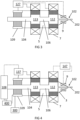
- FIG 1 shows an extruder 100 including a feedstock inlet piece 1 being a piece which includes the inlet 101 through which material can be introduced into the extruder.
- the feedstock inlet piece 1 includes a cooling system, which also benefits the cooling of material, even metal wires, further preventing weakening of the material at the inlet.
- the cooling system shown in FIG 1 is a passive cooling system, for example a heat sink comprising suitable material for dissipating heat, optionally including heat dissipating structures such as fins or the like.
- a channel 104 extends between the inlet 101 and a reservoir 103 of molten material. The channel is narrower than the reservoir.
- the diameter of the channel can be chosen depending on the feedstock material, e.g. for a wire of 1.2 mm, 1.3 mm at the connection with the reservoir, while the reservoir may have a width or diameter of few mm but larger than the diameter of the channel at the connection with it, e.g. about ten, for example 8 mm.
- the length of the reservoir may be provided in accordance with the maximum feedrates to be achieved for a given heating power taking into account heat transfer, etc.
- the channel 104 traverses an insulating piece 2, for example a piece comprising or made of thermally insulating material (e.g. insulating ceramic), so the heat in the reservoir 103 does not weaken the material at the level of the inlet 101 and the heat extracted by zone 1 is limited, to improve energy efficiency.
- insulating piece 2 for example a piece comprising or made of thermally insulating material (e.g. insulating ceramic), so the heat in the reservoir 103 does not weaken the material at the level of the inlet 101 and the heat extracted by zone 1 is limited, to improve energy efficiency.
- the diameter of the channel 104 may not be constant, and it may be adapted to optimize e.g. insulation, reduce buckling or friction, facilitate material entrance, etc.
- the diameter of the channel 104 through the feedstock inlet piece 1 may be different, e.g. larger than through the insulating piece 2, for example it may be 2 mm and 1.3 mm respectively.
- the reservoir 103 is connected to an outlet 102 which provides extruded material 202 (e.g. wire for deposition, e.g. a hot wire).
- the outlet 102 may be configured to provide extrusion forces, e.g. a nozzle 3.
- One heater 4 is provided at the region of the reservoir, to melt material entering the reservoir.
- the heater 4 may include any known suitable system such as induction or resistance heating, liquid/gas heating, etc. Heaters can be at the external part of the extruder, or integrated in the chamber material, or even in contact with the molten material.
- the present invention allows high feedrates, with accelerations of up to 100 mm/s 2 , with no buckling.
- the extruder is configured to prevent flow of molten material towards the inlet.
- the channel 104 is narrower than the reservoir 103 and a temperature gradient is also provided along the channel, so a volume of mushy material forms along the channel, which deforms easily and takes the shape of the channel, sealing it.
- the material being introduced into the reservoir acts as a plunger, pushing the molten material towards the extruder.
- the heater 4 and the cooling system of the feedstock inlet piece 1 are configured to keep the respective high and lower temperatures at opposite extremes of the channel 104, for example at or close to the reservoir 103 and around the bottom of the cooling system respectively.
- the feedrate can be considered when providing the heating and/or cooling for controlling the gradient.
- the mushy zone is relatively small and closer to the reservoir than to the colder area close to the inlet. If the mushy zone is too high in the channel, close to the (cooled) feedstock inlet piece, the mushy material solidifies, causing clogging. It also requires higher extrusion force, increasing the probability of buckling.
- the heating and cooling may be such that the gradient is relatively high, but only at the wire to advantageously limit the power consumption.
- the insulating piece 2 prevents drawing too much heat by the cooling system from the reservoir.
- a small temperature gradient makes the positioning and length of the mushy zone more sensitive to variable feedrates, and its limit tends to extend closer to the feedstock inlet piece 1.
- a high length of the channel before the reservoir further reduces the temperature gradient, increasing the length of the mushy zone. A high length of this zone increases the friction forces, increasing the chance of buckling and clogging.
- the gradient is controlled by a controller 107, so that there is a mushy region blocking upwards flow of molten material from the reservoir to the bottom of the feedstock inlet piece 1.
- the control unit or controller 107 controls the amount of heat provided by the heater 4.
- the controller 107 may provide larger or lower heating, heating close to or surpassing the melting temperature of the material so that the channel is sealed with partially molten material (or mushy zone) to prevent upflow, so the material being fed through the channel behaves as a 'plunger'.
- FIG 2 shows an embodiment of the present invention where active cooling is provided at the feedstock inlet piece 1.
- Active cooling may be provided by any form of controllable liquid or gas (e.g. forced air), thermo-electric or heat pipes.
- the feedstock inlet piece 1 may include an active cooler 109, which may include a circuit of pipes for cooling fluid (gas, liquid such as water, etc.).
- This active cooling system can be controlled, increasing or decreasing the cooling rate according to the particular application. This is advantageous for, for example:
- Active cooling can be combined with a single heater, but some embodiments of the present invention include a plurality of heaters, as shown in FIG 2 , as the temperature of the control of the mushy zone can be different than the required extrusion temperature.
- a plurality of heaters can also be applied to extruders with passive cooling at the feedstock inlet piece, such as the one shown in FIG 1 . Having several heaters allows material within the reservoir to be heated at different zones, for example one zone closer to the channel than to the outlet, and another non-overlapping zone closer to the outlet than to the channel.
- the heaters may heat the material at the same temperature. This can be done for polymers, allowing control of the temperature at the mushy zone and close to the outlet, e.g. at the extrusion zone. Heat extraction in the two zones might be different, so even though the same temperature setpoint is required, it is advantageous to use two different heaters that control (independently) the temperature of the two zones. This is advantageous over current FFF designs, for example.
- the heater or heaters closer to the channel 104 may heat the material at a lower temperature than the heater or heaters further away from the channel. This is advantageous in materials with large thermal conductivity (as in metals), because it allows decoupling the heater of the first reservoir part 113 from the rest of the heaters, e.g.
- the temperature needed to provide the piston effect of the fed material can be controlled by the first heater, while the optimal temperature for extrusion, much higher than the temperature of solid-liquid transition, can be provided by the second heater which heats material at optimal extrusion temperature (e.g. closer to the outlet than to the channel).
- the optimal temperature for extrusion much higher than the temperature of solid-liquid transition
- the second heater which heats material at optimal extrusion temperature (e.g. closer to the outlet than to the channel).
- metals it may be 100°C to 500°C hotter in the second reservoir, while for polymers due to their low conductivity may not be any difference, up to around 50°C hotter.
- first reservoir part 113 where the material is heated by the first heater 4
- second reservoir part 112 where the material is heated by the second heater 7.
- the heaters 4, 7 may be the same or different type, for example they may be optimized for the intended range of temperatures. If the design, process and extrusion material allow it, it can even be the same heater as shown in FIG 1 or one with predefined power distribution.
- the temperature gradient in the fed material can be provided by controlling the cooling rate by a controller 117, by controlling the heating rate of the heater 4 closest to the channel, or by controlling both the cooling rate of the active cooler 109 and the heating rate of the heater 4 closest to the channel. Further, the controller 117 can provide control of the second heater.
- the first and second heaters are thermally insulated from each other at least by a thermal break 5, so their heating rate can be set or controlled accurately.
- This thermal break 5 may be similar as the insulating piece 2, albeit optimized to insulate heat fluxes at a temperature within the range of temperatures of the reservoir.
- FIG 3 shows an embodiment of the present invention where the first reservoir part 113 and the second reservoir part 112 are linked by a thermal break 5 which provides a second channel 106, or necking, with a smaller diameter than the rest of the reservoir 103.
- This diameter can be bigger, equal or smaller than the feeding channel diameter.
- the presence of a channel 106 is relevant for materials with high thermal conductivity and low viscosity, such as liquid metals.
- the diameter might preferable be larger, e.g. as large as the rest of the reservoir (in practice, removing the necking as shown in FIG 2 ).
- a further heater 9 may be added to the outlet.
- an extrusion nozzle at the output may comprise a nozzle tip heater 9, to compensate for heat extraction by the workpiece/printed part and ambient.
- the heating response is high and allows optimal process control. For example, turning off the heater may allow fast cooling of the tip and solidification, improving process control and reducing dripping and the like.
- the further heater 9 can be controlled by the same controller that controls the temperature gradient (the controller 127 that controls e.g. the heater, or an active cooling system, or both).
- nozzle heater 9 might not be required for some materials, e.g. for materials with low melting temperatures, and/or low thermal conductivity.
- FIG 4 shows an embodiment comprising two reservoir parts and a further channel 106 as in FIG 3.
- the present invention may include a controller 137 configured for providing the temperature gradient (e.g. by at least controlling an active cooler 109, or a heater 4 for the first reservoir part 113, or both), and a second controller 147 dedicated to control the extrusion temperatures, e.g. the heater of the second reservoir part 112 and the further heater 9, e.g. tip heater.
- a controller 137 configured for providing the temperature gradient (e.g. by at least controlling an active cooler 109, or a heater 4 for the first reservoir part 113, or both)
- a second controller 147 dedicated to control the extrusion temperatures, e.g. the heater of the second reservoir part 112 and the further heater 9, e.g. tip heater.
- a feeder mechanism 108 for example a feedstock and/or a driving system, can be included to provide a volumetric displacement of the fed material and providing enough pressure to do the extrusion in fully liquid state.
- feedstock and driving system may include feeding wheels.
- the feedstock may comprise a hopper and the driving system for example an extrusion screw.
- This feeder mechanism 108 can be positioned at a predetermined distance from the extruder, for example on the frame of the printer, in a configuration known as Bowden feeding principle. Or the feeder mechanism can directly be installed on top and aligned with the extruder, becoming a part of the printhead. However, it is distant enough not to be affected by the high temperatures managed in the extruder, e.g. it may be placed in an area at temperatures of 50°C or lower, so it may be cold compared to the extruder, so moving parts, seals and other parts of the mechanism has low risk of thermal damage.
- the feeder mechanism can be controlled, for example for providing different feedrates, which result in different extruding rates in embodiments of the present invention.
- the controller 137 used to control the temperature gradient can also or alternatively be used to control feedrate, pressure, etc. by setting appropriate algorithms and connections between the feeder mechanisms 108 and the controller 137, e.g. including a central processing unit.
- the feedrate can be considered and be controlled for the precise control of the temperature gradient along the channel.
- the heating power and temperature gradient can be appropriately chosen so the weakening of the wire does not cause bending or the like.
- the feeder mechanism 108 may be included as part of the extruder of the present invention, for example but not exclusively on the embodiments shown in FIG 2 to FIG 3 .
- Any controller can be used to control the feeder mechanism 108, such as for example the controller 107, 117, 127, 137 which controls the temperature gradient, or even the controller 147 which controls the heaters dedicated to heat at extrusion temperatures.
- the heaters may provide a predetermined power distribution and the cooler may also have fixed or passive cooling, so the temperature gradient of the material in the channel can be controlled by controlling the time from the entry in the extruder until it melts close or in the reservoir, e.g. by controlling the feedrate.
- each heater, feedback mechanisms and optionally active cooler may be controlled with a dedicated controller
- all controllers can be connected to a central processing unit, for example in a computer, which controls all the processes.
- a load cell 400 can be provided to measure extrusion force on the wire, for embodiments using wire as feeding material.
- the load cell is connected to the feeder mechanism 108 and also to the printhead to measure extrusion force. This gives information of the reaction force of the wire pushing on the mushy zone. If the feeder pushes the wire, due to the reaction force of the wire on the mushy zone, the feeder and printhead tend to move apart, which is detected by the load cell 400.
- the load cell may be connected to the controller/CPU, as a sensor input, for feedback.
- the controller may adjust the temperature gradient, or the feedrate if connected to the mechanism, if the sensor detects an unwanted change on the force applied to the wire, which is useful to e.g. reduce bending, buckling and jamming.
- an encoder wheel can be implemented to measure slip of the feeding mechanism. When wire slip is detected, most likely the wire has jammed and the feeding process needs to be stopped.
- pressure-driven extrusion is not required, so no complex pressure systems are necessary.
- a system 300 for applying overpressure on the extruder for example on the reservoir, may be used.
- the overpressure system 300 may be configured to apply a small overpressure of for example lower than 100 mbar of inert gas (in case of aluminium), enough to evacuate oxygen and other reactive gases from the extruder or to prevent those gasses to enter.
- This system is not configured to apply a pressure high enough to drive the extrusion, but it may be enough to protect reactive molten material (e.g. molten metal) and reduce unwanted reactions such as oxidation.
- Feeder mechanisms may not be limited to wire feeding. Any suitable feeding system can be used.
- the feeder mechanism 500 may comprise a screw 501 that is mounted entirely in the cold zone, which allows using many different materials as screw which do not need to withstand high temperatures. However, this is not limiting, and the screw can extend inside the extruder and the channel towards the reservoir.
- the extrusion screw 501 is configured for driving material in the form of granulates or powder. It allows both volumetric displacement and optionally (at least partial) melting of the pellets due to shear and friction, which is advantageous in the melting of polymers. Additional heat is applied by heaters 4.
- the driving mechanism just provides the movement, and the heating is done separately, e.g. they may be controlled by different means, e.g. different controllers.
- the controllers and optional sensors are all connected to a CPU for providing accurate heating, feeding rate and/or cooling, for providing an appropriate temperature gradient.
- the nozzle 3 is a replaceable nozzle.
- the extruder may include a connection to a voltage supply, to provide a voltage between the material in the extruder and the buildplate of a 3D printer.
- FIG 2 , FIG 3 and FIG 4 show the extruder comprising several pieces attached to heaters 4, 7 and separated by an insulation piece providing a thermal break 5.
- the thermal break 5 can be realized by geometrical design, such a small channel diameter, smaller outer diameter, presence of fins, etc.
- the part forming the thermal break may be a shaped portion of the reservoir, as shown in FIG 6.
- FIG 6 shows a single block of material enclosing the reservoir.
- the heaters may be an integral part of the extruder.
- Additional heaters can be included depending on the required extrusion speed range and material properties of the extrusion material.
- FIG 7 shows an additional heater 71 in the break 5 between the first reservoir part 113 and second reservoir part 112. This allows a higher range of extrusion speeds. At low speeds, additional heating might be required to prevent solidification in that area. At high speeds, additional heating might be required to help the heater 7 closest to the outlet to reach the extrusion temperature. Additionally, the heater of each area may include a plurality of heating units, for example a plurality of heating resistors or a plurality of inductors which may be individually powered and/or controlled.
- the present invention provides a method of extrusion of material, which can be used during 3D printing.
- the method allows volumetric extrusion of metals or polymers without the need of high-pressure systems, with low or no dripping/oozing, and with fast and high range of deposition rates.
- the method is carried out using an extruder with a reservoir, such as the extruder of the first aspect of the present invention.
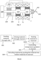
- FIG 8 is a chart with steps of the method.
- the method includes filling the reservoir with molten material, for example by heating S030 melting material in the reservoir using a heater.
- the initial filling procedure includes the following steps:
- Material is introduced S01 or fed through a feedstock inlet piece, sending S02 it through a channel into the reservoir. There, the material is heated S030.
- the channel is narrower than the reservoir, and additionally, a temperature gradient is formed and controlled S03 between the (bottom of the feedstock inlet piece 1 and the reservoir 103, i.e. though the channel, so the mushy zone is kept in the area of the channel preferably at the insulating piece, preferably closer to the reservoir than to the inlet 101.
- the gradient allows, in a first instance, to keep molten material at the junction between the channel and the reservoir, preventing upwards flow from reaching the inlet.
- the temperature gradient may be arranged so at least partially molten material is present within the channel.
- the method of the present invention allows volumetric extrusion by the pushing/displacement of the fed material, both for polymer and metal materials, with a stable printing, low or no dripping and oozing.
- the method allows extruding S04 material by pushing fed material into molten material of reservoir.
- the temperature gradient can be provided by control of heat flow at opposite sides of the channel, e.g. at the feedstock inlet piece and at the reservoir. This can be done by e.g. controlling the heating rate of a heater at the reservoir, and/or controlling cooling rate of a cooler at the region of the inlet, e.g. in a feedstock inlet piece.
- Control can be provided by control signals, by a feedback loop, etc. provided by an electronic component such as a controller, a processor or the like.
- the controller may provide signals to change the heat flow, e.g. changing the heating power at the reservoir side, or changing the cooling power at the inlet side, and/or by adapting the feedrate.
- Introducing S01 material may comprise introducing metal.
- it comprises introducing only metallic material or alloys, without being mixed with resin.
- metallic material or alloys for example, aluminum or aluminum alloy, silver, gold, magnesium. or copper can be provided.
- the metal may be provided for example in the form of a metal wire.
- the method may comprise providing polymer such as PLA, ABS, PP, PEEK, nylon, PC, e.g. in the form of a wire, or pellets or granulates, the present invention not being limited to these examples.
- the extrusion physics between metals and polymers there is not much difference between the extrusion physics between metals and polymers.
- wire When wire is fed to the extruder, it is advantageous to ensure that the fed wire provides the extrusion force. This is relatively easy to provide with polymers at low feedrates, due to their high viscosity.
- the present invention provides extra friction against the motion of molten polymer upwards the channel and allowing a longer length for the wire melting zone (at higher feedrates), thanks to the difference in width between the reservoir and the channel.
- a cooling area such as a heat sink, optionally also a heat break could be used.
- the fed material can be driven S02 through the channel from the inlet, optionally a cooled inlet, through the heat break provided by an insulating piece, into the reservoir.
- the present invention allows using metals or polymers with the same architecture (although the design, used material and dimensions may vary depending on the material for extrusion) despite the difference of properties such as high thermal conduction (often 2 or 3 orders of magnitude higher than polymers), together with the required high melting temperatures of metals, which may cause a long weak zone (specially in materials with high conductivity such as metals).
- metals can be extruded relatively fast. Polymers, due to their high viscosity and limited maximum heat applicable, are difficult to extrude at a high rate. For high feedrates or speeds, the long weak/melting zone becomes a problem for both polymer and metal extrusion. A large back pressure of the wire on the extruder leads to slipping of the wire in the feeding system (non volumetric extrusion) or buckling.
- the particular configuration of the channel and the reservoir and the temperature gradient control allows reducing or preventing a long weakening zone, further providing a sealing effect at the channel or between the channel and the reservoir so no molten material flows up the channel, and the fed material itself creates pressure on the molten material of the reservoir, thereby providing extrusion.
- the method allows control of the extrusion process by controlling the feedrate.
- the method comprises providing feeding material into the inlet and channel, where the material is chosen so that a gap can be formed between the solid material and the channel.
- the width of diameter of a feeding wire can be chosen accordingly with the channel width.
- a wire diameter of e.g. 1.2 mm a channel diameter of 1.25 mm-1.5 mm has been proven to work.
- these values are only an example, and other values can be applied depending on the used material properties, gap size and temperature gradient.
- the method allows turning the fed material into a consumable piston, so the fed material pushes on the molten material while transitioning from solid state to molten state, thanks to the buffer reservoir.
- the temperature at the inlet may be kept the same, for example thanks to a cooler.
- the temperature at the reservoir may also be constant thanks to the heater.
- the local temperature of material in the reservoir at the connection with the channel may be lower than on the rest of the reservoir. This can be taken into account and the temperature setpoint may be increased.
- the influence of thermal conduction is high, and heat can travel upwards towards the inlet from the reservoir. This is an important issue in wire fed material, especially on metals.
- the gradient along the fed material is controlled so that the mushy zone, where the solid material becomes molten, takes place along the channel, preferably close to the reservoir, e.g. along the insulating piece 2. This is shown in FIG 9 .
- the unmolten or partially molten material can travel inside the buffer reservoir.
- the mushy zone of the wire will be somewhere in the reservoir. This is shown in FIG 10 .
- the material e.g. wire
- it will push some liquid upwards in the feeding channel as this is most likely the path of least resistance compared to the nozzle opening.
- the molten material partially solidifies, creating a mushy zone at the top of the reservoir along the channel, but limited to a small length or portion 1042 of the channel 104, so the piston effect of the material is restored.
- a careful engineering of the gap between the material and the channel also improves the piston effect.
- the control of the temperature gradient is important to ensure control of the melting process (e.g. the position of the mushy zone) and, in case of wire-fed material, a short length of the weakening zone to reduce chances of friction, buckling and clogging.
- the buffer allows longer melting lengths without introducing extra friction or controlling different position of the mushy/piston zone, as long as the gradient allows sealing of the reservoir by at least partially molten material.
- a feedrate is high or low depending on its conductivity and it determines whether melting takes place in the reservoir or along the channel. The present invention allows controlling and sustaining the presence of a mushy zone along the channel, either way.
- a second heating which may be different from the first, can be applied to the material in the reservoir leaving to the outlet.
- heating material for providing the temperature gradient can be performed independently from heating the material for extrusion.
- the first heater may be controlled independently from the second heater.
- both heaters may heat the material at the same molten temperature. These temperatures depend on the material; for PLA, typically 185°C to about 205°C; for ABS, typically 200°C to 250°C; for PEEK: 340°C-575°C.
- the material may be heated at the metal melting temperature in the first reservoir part heated by the first heater close to the channel, while the material may be heated at much higher temperatures, suitable for stable continuous extrusion and fusion with previous layers, in the second reservoir part close to the outlet.
- extruded material can be further heated during extrusion, for example by means of an extra heater at the outlet, e.g. at the extrusion nozzle. Because the amount of material is small along the nozzle, the heating and cooling can be very fast, facilitating for example fast solidification at the end of a deposition cycle or allowing fast melting at the start of a cycle.
- Controlling the heater for controlling the temperature gradient, controlling the heater or heaters for providing optimal extrusion temperature, controlling of the cooler for controlling the temperature gradient and/or control of the feedrate can be done by means of one or more controllers.
- control of the heating and/or cooling for providing the temperature gradient is done independently of the control of the feedrate.
- the feedrate can be used as input data to optimize temperature gradient control. The control can be improved further in case of wire-fed materials by measuring the force on the solid wire while feeding it to the extruded.
- the method may comprise applying a light overpressure of an inert gas to reduce oxidation, which is especially advantageous in case of metal printing.
- This overpressure may not be as high enough so as to produce extrusion, so the gas system may be small and not requiring a large power.
- the method can be used for both polymers and metals, taking into account issues such as heat conductivity (which is usually 2 to 3 orders of magnitudes higher in metals than the usual polymers), different melting temperatures and chemical interactions.
- the temperature of extrusion due to low melting temperatures and heat conductivity.
- at least two temperatures can be advantageously controlled to prevent clogging: solid to liquid transition and extrusion temperature.
- two heaters for heating different regions of the reservoir optionally including a heater at the outlet (e.g. nozzle tip heater 9), can advantageously be used for metal extrusion.
- the number of heaters may be higher, for example each part of the reservoir may be heated by more than one heater, so more control bandwidth can be provided, advantageously increasing the range of available feedrates.
- introducing material includes driving granulates of polymer or metal into the extruder.
- An extrusion screw or pump for non-molten particles feeds the granulates to the entrance of the reservoir.
- the driving force compacts the granulates, but no plastic deformation is necessary, and air pockets may be present between the granulates.
- the screw/feeding mechanism can be completely in the cold zone, advantageously fulfilling (thermo)mechanical requirements of the design and material choice.
- the granulates start to weaken and transition to molten state along the channel 104 where the mushy zone is formed.
- the granulates do not have time to melt prior to enter the reservoir. Both in the case of the wire and this case, the displaced volume pushes the molten material through the nozzle. An amount of material may flow upwards the channel. This amount is limited by the narrowing between the reservoir and the channel, and by the temperature gradient through the channel 104 where material is (at least partially) solidified and forming a mushy zone that acts as a piston.
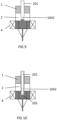
- FIG 9 and FIG 10 shows the difference in operation between low feedrates and high feedrates. It is noted that the conductivity is an important factor, as well as the speed of the insertion of material, which determines the behaviour of the material.
- the solid feedstock is in these examples wire, but the same may apply to other forms of material.
- FIG 9 shows the behaviour at low feedrates, with the mushy zone in the portion 1042 of the insulating piece 2 closer to the reservoir (e.g. the half of the piece closer to the reservoir, or even closer).
- the material 201 acts as a consumable piston, the process of melting starts before the reservoir and the mushy material deforms and takes the shape of the channel, avoiding uncontrolled upflow reaching the inlet.
- the temperature gradient is kept high in this portion 1042 by control of heating, and/or of cooling, and rates thereof.
- FIG 10 shows the behaviour at high feedrates, with the mushy zone 203 of the wire 201 within the reservoir, where the material melts.
- the fed material pushes on the molten material within the reservoir and pushes it towards the outlet.
- the material starts transitioning from molten to solid state due to cooling, and it fills the space between the wire (although the same applies if a different form is used, such as powder) and the inner walls of the channel.
- this movement and its extent is controlled by controlling the temperature gradient, so the flow stays in the portion 1042 of the channel 104 along the insulating piece 2.
- the temperature gradient is kept high in this portion 1042 by control of heating (with the heater 4), optionally or additionally cooling (with cooler at the feedstock inlet piece 1), and rates thereof.
- the process is continuous, and it can continuously stabilize itself, by controlling the temperature gradient, optionally also the extrusion temperature and feedrate.
- the present method and device allow volumetric extrusion in a wide variety of feedrates. It also makes possible metal extrusion in fully liquid state, while preventing oozing or dripping, and not limited to wire feedstock. It is not limited to metals, as it can be used to extrude materials with a wide variety of viscosities, including polymers, even foodstuffs.
Landscapes
- Engineering & Computer Science (AREA)
- Chemical & Material Sciences (AREA)
- Materials Engineering (AREA)
- Mechanical Engineering (AREA)
- Manufacturing & Machinery (AREA)
- Physics & Mathematics (AREA)
- Optics & Photonics (AREA)
- Thermal Sciences (AREA)
- Health & Medical Sciences (AREA)
- Clinical Laboratory Science (AREA)
- Extrusion Moulding Of Plastics Or The Like (AREA)
- Powder Metallurgy (AREA)
Claims (11)
- Ein Extruder (100) für 3D-Druck, der einen Auslass (102) zum Bereitstellen von extrudiertem Material (202) und ein Beschickungsmaterialeinlassstück (1) zum Aufnehmen von Material in den Extruder umfasst,- das Beschickungsmaterialeinlassstück (1) ein Kühlmittel zum Kühlen des Materials beinhaltet,- ein Reservoir (103) für Schmelzmaterial und das eine Reservoirbreite aufweist, das mit dem Auslass (102) verbunden ist,- einen Kanal (104) mit einer Kanalbreite, um das Beschickungsmaterialeinlassstück (1) mit dem Reservoir (103) zu verbinden und das Material in das Reservoir einzuleiten, wo die Kanalbreite geringer als die Reservoirbreite ist,
wobei der Extruder (100) weiter Folgendes umfasst- eine erste Heizung (4) zum Schmelzen von Material in einem ersten Reservoirteil (113) des Reservoirs (103) nahe dem Kanal und- eine zweite Heizung (7) nahe der Verbindung des Reservoirs mit dem Auslass (102), um geschmolzenes Material in einem zweiten Reservoirteil (112) des Reservoirs nahe dem Auslass (102) auf der gleichen Temperatur wie das Material in dem ersten Reservoirteil (113) oder auf einer höheren Temperatur zu halten, und- eine Steuereinheit (107, 117) zum Steuern des Temperaturgradienten des Materials durch den Kanal (104), wobei die Steuereinheit dazu konfiguriert ist, den Pegel geschmolzenen Materials mindestens an dem Übergang zwischen dem Reservoir (103) und dem Kanal (104) oder entlang des Kanals (104) während Extrusion aufrechtzuerhalten, um Extrusion durch das Material bereitzustellen, das durch das Beschickungsmaterialeinlassstück eingeleitet wird, und das geschmolzene Material in dem Reservoir (103) weiterzudrücken,dadurch gekennzeichnet, dass die erste Heizung von der zweiten Heizung (7) durch eine Wärmesperre (5) beabstandet ist, die das Reservoir in den ersten Reservoirteil (113) nahe dem Kanal (104) und den zweiten Reservoirteil (112) nahe dem Auslass (102) trennt. - Der Extruder des vorstehenden Anspruchs, wobei die Steuereinheit (107, 117) dazu konfiguriert ist, die Heizung zu steuern, und/oder wobei das Kühlmittel einen aktiven Kühler (109) beinhaltet, wobei die Steuereinheit (117) dazu konfiguriert ist, den aktiven Kühler (109) zu steuern, um die Abkühlrate des Materials zu steuern.
- Der Extruder nach einem der vorstehenden Ansprüche, der weiter eine Materialzuführung (108, 500) zum Zuführen von Material in das Beschickungsmaterialeinlassstück (1) umfasst, wobei die Steuereinheit (117) weiter dazu konfiguriert ist, die Materialzuführung (108, 500) zu steuern, um die Zufuhrrate zu steuern.
- Der Extruder nach Anspruch 3, wobei die Materialzuführung (108) eine Drahtzuführung (108) zum Zuführen von Draht (201) ist und er weiter eine Kraftmesszelle (400) zwischen der Drahtzuführung (108) und dem Beschickungsmaterialeinlassstück (1) zum Messen der auf den Draht (201) wirkenden Extrusionskraft umfasst.
- Der Extruder nach einem der vorstehenden Ansprüche, wobei die Wärmesperre (5) einen weiteren Kanal (106) bereitstellt, der dazu geeignet ist, den ersten Teil (112) von dem zweiten Teil (113) des Reservoirs thermisch zu isolieren.
- Der Extruder nach einem der vorstehenden Ansprüche, wobei der Auslass (102) eine weitere Heizung (9) zum Steuern der Temperatur des extrudierten Materials (202) bei dem Auslass umfasst.
- Der Extruder nach einem der vorstehenden Ansprüche, der weiter ein Isolierstück (2) umfasst, das mindestens einen Abschnitt des Kanals (104) umfasst, um das Beschickungsmaterialeinlassstück (1) thermisch von dem Reservoir (103) zu isolieren.
- Der Extruder nach einem der vorstehenden Ansprüche, der weiter Elektroden umfasst, die dazu konfiguriert sind, eine Spannung zwischen dem Extruder und einer Bauplatte eines 3D-Druckers anzulegen.
- Ein Verfahren zum Extrudieren von Material, umfassend- Einleiten (S01) von Material in einen Extruder durch ein Beschickungsmaterialeinlassstück,- Erhitzen (S030) von Material in einem ersten Teil eines Reservoirs, um einen Pegel von geschmolzenem Material zu erhalten, während die Erhitzung des Materials durch das Beschickungsmaterialeinlassstück verhindert wird, und Anwenden eines zweiten Erhitzens in einem zweiten Teil des Reservoirs auf Material, das das Reservoir verlässt,- Zuführen (S02) von Material in das Reservoir durch einen Kanal, wobei der Kanal eine Kanalbreite aufweist und das Reservoir eine Reservoirbreite aufweist, wobei die Kanalbreite geringer ist als die Reservoirbreite,- Steuern (S03) des Temperaturgradienten entlang des Kanals, um den Pegel geschmolzenen Materials an dem Übergang zwischen dem Reservoir und dem Kanal oder entlang des Kanals während Extrusion aufrechtzuerhalten,sodass Einleiten weiteren festen Materials in das Reservoir das geschmolzene Material in dem Reservoir durch einen Auslass weiterdrückt, der mit dem Reservoir verbunden ist, wodurch extrudiertes Material gebildet (S04) wird,dadurch gekennzeichnet, dass das Erhitzen von Material in dem Reservoir Erhitzen von Material in einem Reservoir umfasst, wobei der erste Teil des Reservoirs durch eine Wärmesperre von dem zweiten Teil getrennt ist.
- Das Verfahren des vorstehenden Anspruchs, das weiter Steuern der Zufuhrrate umfasst und/oder wobei Abkühlen des Materials Steuern der Abkühlrate umfasst.
- Das Verfahren nach einem der Ansprüche 9 oder 10 zum Extrudieren von Aluminium, einer Aluminiumlegierung oder Kupfer.
Applications Claiming Priority (2)
| Application Number | Priority Date | Filing Date | Title |
|---|---|---|---|
| EP21171243.5A EP4082756B1 (de) | 2021-04-29 | 2021-04-29 | Extrusion für den 3d-druck |
| PCT/EP2022/061479 WO2022229385A1 (en) | 2021-04-29 | 2022-04-29 | Extrusion for 3d printing |
Publications (3)
| Publication Number | Publication Date |
|---|---|
| EP4330014A1 EP4330014A1 (de) | 2024-03-06 |
| EP4330014C0 EP4330014C0 (de) | 2025-06-04 |
| EP4330014B1 true EP4330014B1 (de) | 2025-06-04 |
Family
ID=75746286
Family Applications (2)
| Application Number | Title | Priority Date | Filing Date |
|---|---|---|---|
| EP21171243.5A Active EP4082756B1 (de) | 2021-04-29 | 2021-04-29 | Extrusion für den 3d-druck |
| EP22726123.7A Active EP4330014B1 (de) | 2021-04-29 | 2022-04-29 | Extrusion für den 3d-druck |
Family Applications Before (1)
| Application Number | Title | Priority Date | Filing Date |
|---|---|---|---|
| EP21171243.5A Active EP4082756B1 (de) | 2021-04-29 | 2021-04-29 | Extrusion für den 3d-druck |
Country Status (9)
| Country | Link |
|---|---|
| US (1) | US20240216990A1 (de) |
| EP (2) | EP4082756B1 (de) |
| JP (1) | JP2024521017A (de) |
| KR (1) | KR20240016269A (de) |
| AU (1) | AU2022267801A1 (de) |
| CA (1) | CA3217102A1 (de) |
| ES (2) | ES2974608T3 (de) |
| PL (2) | PL4082756T3 (de) |
| WO (1) | WO2022229385A1 (de) |
Families Citing this family (1)
| Publication number | Priority date | Publication date | Assignee | Title |
|---|---|---|---|---|
| CN116690979B (zh) * | 2023-05-12 | 2024-04-05 | 杭州德硕智能科技有限公司 | Fdm型增材打印机 |
Family Cites Families (6)
| Publication number | Priority date | Publication date | Assignee | Title |
|---|---|---|---|---|
| US9956725B2 (en) * | 2013-03-22 | 2018-05-01 | Markforged, Inc. | Three dimensional printer for fiber reinforced composite filament fabrication |
| US20160354977A1 (en) * | 2015-06-07 | 2016-12-08 | Mark Christopher Gordon | Fused filament fabrication extruder |
| US11104058B2 (en) | 2017-05-31 | 2021-08-31 | Stratasys, Inc. | System and method for 3D printing with metal filament materials |
| US20190091933A1 (en) * | 2017-09-22 | 2019-03-28 | Desktop Metal, Inc. | Method And Apparatus For Controlling Heat For Improved Extrudate Flow In Three-Dimensional (3D) Printing |
| US20200346399A1 (en) * | 2018-01-18 | 2020-11-05 | Arctic Biomaterials Oy | Fiber-reinforced 3d printing |
| DE102019002203B3 (de) * | 2019-03-22 | 2020-07-16 | ThixoAM GmbH | Verfahren und Vorrichtung für die additive Fertigung von Erzeugnissen aus Metalllegierungen |
-
2021
- 2021-04-29 PL PL21171243.5T patent/PL4082756T3/pl unknown
- 2021-04-29 EP EP21171243.5A patent/EP4082756B1/de active Active
- 2021-04-29 ES ES21171243T patent/ES2974608T3/es active Active
-
2022
- 2022-04-29 US US18/558,078 patent/US20240216990A1/en active Pending
- 2022-04-29 KR KR1020237040890A patent/KR20240016269A/ko active Pending
- 2022-04-29 JP JP2023566946A patent/JP2024521017A/ja active Pending
- 2022-04-29 CA CA3217102A patent/CA3217102A1/en active Pending
- 2022-04-29 EP EP22726123.7A patent/EP4330014B1/de active Active
- 2022-04-29 ES ES22726123T patent/ES3037134T3/es active Active
- 2022-04-29 AU AU2022267801A patent/AU2022267801A1/en active Pending
- 2022-04-29 WO PCT/EP2022/061479 patent/WO2022229385A1/en not_active Ceased
- 2022-04-29 PL PL22726123.7T patent/PL4330014T3/pl unknown
Also Published As
| Publication number | Publication date |
|---|---|
| EP4082756C0 (de) | 2023-11-22 |
| ES3037134T3 (en) | 2025-09-29 |
| ES2974608T3 (es) | 2024-06-28 |
| EP4330014C0 (de) | 2025-06-04 |
| PL4330014T3 (pl) | 2025-08-18 |
| EP4082756A1 (de) | 2022-11-02 |
| EP4082756B1 (de) | 2023-11-22 |
| WO2022229385A1 (en) | 2022-11-03 |
| AU2022267801A1 (en) | 2023-11-16 |
| PL4082756T3 (pl) | 2024-06-24 |
| EP4330014A1 (de) | 2024-03-06 |
| KR20240016269A (ko) | 2024-02-06 |
| US20240216990A1 (en) | 2024-07-04 |
| JP2024521017A (ja) | 2024-05-28 |
| CA3217102A1 (en) | 2022-11-03 |
Similar Documents
| Publication | Publication Date | Title |
|---|---|---|
| US11241741B2 (en) | Thermally robust nozzle for 3-dimensional printing and methods of using same | |
| US11260587B2 (en) | 3D printhead comprising additional temperature control means | |
| US10542589B2 (en) | Electromagnetic print nozzle for direct-write additive manufacturing with resistive renditions | |
| US11104058B2 (en) | System and method for 3D printing with metal filament materials | |
| US9561540B2 (en) | Die casting nozzle and method for operating a die casting nozzle | |
| US9889604B2 (en) | Device for the production of a three-dimensional object | |
| US11806934B2 (en) | Methods and apparatus for additive manufacturing utilizing multifunctional composite materials, and articles made therefrom | |
| EP4330014B1 (de) | Extrusion für den 3d-druck | |
| US20230226609A9 (en) | Three-dimensional printing method | |
| EP3663073A1 (de) | 3d-druck-kopfsystem mit kombinierten verarbeitungsabschnitten und einem integral angeformten verarbeitungskanal für die generative fertigung | |
| US12109612B2 (en) | Additive manufacturing method | |
| NL2026789B1 (nl) | Flow control in an extruder head | |
| SE506043C2 (sv) | Förfarande vid formsprutning | |
| US11883879B1 (en) | System and method for controlling flow through a 3D printer | |
| US12569914B2 (en) | System and method for controlling flow through a 3D printer | |
| US12053929B2 (en) | Build units for three-dimensional printers | |
| KR20240045784A (ko) | 3d 프린터 히팅 블록 냉각 제어장치 및 방법 |
Legal Events
| Date | Code | Title | Description |
|---|---|---|---|
| STAA | Information on the status of an ep patent application or granted ep patent |
Free format text: STATUS: UNKNOWN |
|
| STAA | Information on the status of an ep patent application or granted ep patent |
Free format text: STATUS: THE INTERNATIONAL PUBLICATION HAS BEEN MADE |
|
| PUAI | Public reference made under article 153(3) epc to a published international application that has entered the european phase |
Free format text: ORIGINAL CODE: 0009012 |
|
| STAA | Information on the status of an ep patent application or granted ep patent |
Free format text: STATUS: REQUEST FOR EXAMINATION WAS MADE |
|
| 17P | Request for examination filed |
Effective date: 20231126 |
|
| AK | Designated contracting states |
Kind code of ref document: A1 Designated state(s): AL AT BE BG CH CY CZ DE DK EE ES FI FR GB GR HR HU IE IS IT LI LT LU LV MC MK MT NL NO PL PT RO RS SE SI SK SM TR |
|
| DAV | Request for validation of the european patent (deleted) | ||
| DAX | Request for extension of the european patent (deleted) | ||
| GRAP | Despatch of communication of intention to grant a patent |
Free format text: ORIGINAL CODE: EPIDOSNIGR1 |
|
| STAA | Information on the status of an ep patent application or granted ep patent |
Free format text: STATUS: GRANT OF PATENT IS INTENDED |
|
| INTG | Intention to grant announced |
Effective date: 20241126 |
|
| GRAS | Grant fee paid |
Free format text: ORIGINAL CODE: EPIDOSNIGR3 |
|
| GRAA | (expected) grant |
Free format text: ORIGINAL CODE: 0009210 |
|
| STAA | Information on the status of an ep patent application or granted ep patent |
Free format text: STATUS: THE PATENT HAS BEEN GRANTED |
|
| RAP3 | Party data changed (applicant data changed or rights of an application transferred) |
Owner name: VALCUN BV |
|
| AK | Designated contracting states |
Kind code of ref document: B1 Designated state(s): AL AT BE BG CH CY CZ DE DK EE ES FI FR GB GR HR HU IE IS IT LI LT LU LV MC MK MT NL NO PL PT RO RS SE SI SK SM TR |
|
| REG | Reference to a national code |
Ref country code: GB Ref legal event code: FG4D |
|
| REG | Reference to a national code |
Ref country code: CH Ref legal event code: EP |
|
| REG | Reference to a national code |
Ref country code: DE Ref legal event code: R096 Ref document number: 602022015545 Country of ref document: DE |
|
| REG | Reference to a national code |
Ref country code: IE Ref legal event code: FG4D |
|
| U01 | Request for unitary effect filed |
Effective date: 20250704 |
|
| U07 | Unitary effect registered |
Designated state(s): AT BE BG DE DK EE FI FR IT LT LU LV MT NL PT RO SE SI Effective date: 20250710 |
|
| REG | Reference to a national code |
Ref country code: ES Ref legal event code: FG2A Ref document number: 3037134 Country of ref document: ES Kind code of ref document: T3 Effective date: 20250929 |
|
| PG25 | Lapsed in a contracting state [announced via postgrant information from national office to epo] |
Ref country code: GR Free format text: LAPSE BECAUSE OF FAILURE TO SUBMIT A TRANSLATION OF THE DESCRIPTION OR TO PAY THE FEE WITHIN THE PRESCRIBED TIME-LIMIT Effective date: 20250905 |
|
| PG25 | Lapsed in a contracting state [announced via postgrant information from national office to epo] |
Ref country code: HR Free format text: LAPSE BECAUSE OF FAILURE TO SUBMIT A TRANSLATION OF THE DESCRIPTION OR TO PAY THE FEE WITHIN THE PRESCRIBED TIME-LIMIT Effective date: 20250604 |
|
| PG25 | Lapsed in a contracting state [announced via postgrant information from national office to epo] |
Ref country code: RS Free format text: LAPSE BECAUSE OF FAILURE TO SUBMIT A TRANSLATION OF THE DESCRIPTION OR TO PAY THE FEE WITHIN THE PRESCRIBED TIME-LIMIT Effective date: 20250904 |
|
| PG25 | Lapsed in a contracting state [announced via postgrant information from national office to epo] |
Ref country code: IS Free format text: LAPSE BECAUSE OF FAILURE TO SUBMIT A TRANSLATION OF THE DESCRIPTION OR TO PAY THE FEE WITHIN THE PRESCRIBED TIME-LIMIT Effective date: 20251004 |
|
| PG25 | Lapsed in a contracting state [announced via postgrant information from national office to epo] |
Ref country code: SM Free format text: LAPSE BECAUSE OF FAILURE TO SUBMIT A TRANSLATION OF THE DESCRIPTION OR TO PAY THE FEE WITHIN THE PRESCRIBED TIME-LIMIT Effective date: 20250604 |
|
| PG25 | Lapsed in a contracting state [announced via postgrant information from national office to epo] |
Ref country code: CZ Free format text: LAPSE BECAUSE OF FAILURE TO SUBMIT A TRANSLATION OF THE DESCRIPTION OR TO PAY THE FEE WITHIN THE PRESCRIBED TIME-LIMIT Effective date: 20250604 |
|
| PG25 | Lapsed in a contracting state [announced via postgrant information from national office to epo] |
Ref country code: SK Free format text: LAPSE BECAUSE OF FAILURE TO SUBMIT A TRANSLATION OF THE DESCRIPTION OR TO PAY THE FEE WITHIN THE PRESCRIBED TIME-LIMIT Effective date: 20250604 |
|
| PGFP | Annual fee paid to national office [announced via postgrant information from national office to epo] |
Ref country code: GB Payment date: 20260324 Year of fee payment: 5 |
|
| PLBE | No opposition filed within time limit |
Free format text: ORIGINAL CODE: 0009261 |
|
| STAA | Information on the status of an ep patent application or granted ep patent |
Free format text: STATUS: NO OPPOSITION FILED WITHIN TIME LIMIT |
|
| REG | Reference to a national code |
Ref country code: CH Ref legal event code: L10 Free format text: ST27 STATUS EVENT CODE: U-0-0-L10-L00 (AS PROVIDED BY THE NATIONAL OFFICE) Effective date: 20260416 |