EP4329657B1 - Vorrichtung zur kontaktlosen echtzeit-hauttemperaturmessung - Google Patents
Vorrichtung zur kontaktlosen echtzeit-hauttemperaturmessung Download PDFInfo
- Publication number
- EP4329657B1 EP4329657B1 EP22723897.9A EP22723897A EP4329657B1 EP 4329657 B1 EP4329657 B1 EP 4329657B1 EP 22723897 A EP22723897 A EP 22723897A EP 4329657 B1 EP4329657 B1 EP 4329657B1
- Authority
- EP
- European Patent Office
- Prior art keywords
- emr
- temperature
- fluorescent
- source
- dopants
- Prior art date
- Legal status (The legal status is an assumption and is not a legal conclusion. Google has not performed a legal analysis and makes no representation as to the accuracy of the status listed.)
- Active
Links
Images


Classifications
-
- A—HUMAN NECESSITIES
- A61—MEDICAL OR VETERINARY SCIENCE; HYGIENE
- A61B—DIAGNOSIS; SURGERY; IDENTIFICATION
- A61B18/00—Surgical instruments, devices or methods for transferring non-mechanical forms of energy to or from the body
- A61B18/18—Surgical instruments, devices or methods for transferring non-mechanical forms of energy to or from the body by applying electromagnetic radiation, e.g. microwaves
- A61B18/20—Surgical instruments, devices or methods for transferring non-mechanical forms of energy to or from the body by applying electromagnetic radiation, e.g. microwaves using laser
- A61B18/203—Surgical instruments, devices or methods for transferring non-mechanical forms of energy to or from the body by applying electromagnetic radiation, e.g. microwaves using laser applying laser energy to the outside of the body
-
- A—HUMAN NECESSITIES
- A61—MEDICAL OR VETERINARY SCIENCE; HYGIENE
- A61B—DIAGNOSIS; SURGERY; IDENTIFICATION
- A61B5/00—Measuring for diagnostic purposes; Identification of persons
- A61B5/0059—Measuring for diagnostic purposes; Identification of persons using light, e.g. diagnosis by transillumination, diascopy, fluorescence
- A61B5/0071—Measuring for diagnostic purposes; Identification of persons using light, e.g. diagnosis by transillumination, diascopy, fluorescence by measuring fluorescence emission
-
- A—HUMAN NECESSITIES
- A61—MEDICAL OR VETERINARY SCIENCE; HYGIENE
- A61B—DIAGNOSIS; SURGERY; IDENTIFICATION
- A61B5/00—Measuring for diagnostic purposes; Identification of persons
- A61B5/01—Measuring temperature of body parts ; Diagnostic temperature sensing, e.g. for malignant or inflamed tissue
-
- A—HUMAN NECESSITIES
- A61—MEDICAL OR VETERINARY SCIENCE; HYGIENE
- A61B—DIAGNOSIS; SURGERY; IDENTIFICATION
- A61B5/00—Measuring for diagnostic purposes; Identification of persons
- A61B5/44—Detecting, measuring or recording for evaluating the integumentary system, e.g. skin, hair or nails
- A61B5/441—Skin evaluation, e.g. for skin disorder diagnosis
-
- A—HUMAN NECESSITIES
- A61—MEDICAL OR VETERINARY SCIENCE; HYGIENE
- A61B—DIAGNOSIS; SURGERY; IDENTIFICATION
- A61B5/00—Measuring for diagnostic purposes; Identification of persons
- A61B5/48—Other medical applications
- A61B5/4836—Diagnosis combined with treatment in closed-loop systems or methods
-
- A—HUMAN NECESSITIES
- A61—MEDICAL OR VETERINARY SCIENCE; HYGIENE
- A61B—DIAGNOSIS; SURGERY; IDENTIFICATION
- A61B17/00—Surgical instruments, devices or methods
- A61B2017/00017—Electrical control of surgical instruments
- A61B2017/00022—Sensing or detecting at the treatment site
- A61B2017/00057—Light
-
- A—HUMAN NECESSITIES
- A61—MEDICAL OR VETERINARY SCIENCE; HYGIENE
- A61B—DIAGNOSIS; SURGERY; IDENTIFICATION
- A61B18/00—Surgical instruments, devices or methods for transferring non-mechanical forms of energy to or from the body
- A61B2018/00005—Cooling or heating of the probe or tissue immediately surrounding the probe
-
- A—HUMAN NECESSITIES
- A61—MEDICAL OR VETERINARY SCIENCE; HYGIENE
- A61B—DIAGNOSIS; SURGERY; IDENTIFICATION
- A61B18/00—Surgical instruments, devices or methods for transferring non-mechanical forms of energy to or from the body
- A61B2018/00005—Cooling or heating of the probe or tissue immediately surrounding the probe
- A61B2018/00011—Cooling or heating of the probe or tissue immediately surrounding the probe with fluids
- A61B2018/00017—Cooling or heating of the probe or tissue immediately surrounding the probe with fluids with gas
-
- A—HUMAN NECESSITIES
- A61—MEDICAL OR VETERINARY SCIENCE; HYGIENE
- A61B—DIAGNOSIS; SURGERY; IDENTIFICATION
- A61B18/00—Surgical instruments, devices or methods for transferring non-mechanical forms of energy to or from the body
- A61B2018/00005—Cooling or heating of the probe or tissue immediately surrounding the probe
- A61B2018/00011—Cooling or heating of the probe or tissue immediately surrounding the probe with fluids
- A61B2018/00023—Cooling or heating of the probe or tissue immediately surrounding the probe with fluids closed, i.e. without wound contact by the fluid
-
- A—HUMAN NECESSITIES
- A61—MEDICAL OR VETERINARY SCIENCE; HYGIENE
- A61B—DIAGNOSIS; SURGERY; IDENTIFICATION
- A61B18/00—Surgical instruments, devices or methods for transferring non-mechanical forms of energy to or from the body
- A61B2018/00315—Surgical instruments, devices or methods for transferring non-mechanical forms of energy to or from the body for treatment of particular body parts
- A61B2018/00452—Skin
-
- A—HUMAN NECESSITIES
- A61—MEDICAL OR VETERINARY SCIENCE; HYGIENE
- A61B—DIAGNOSIS; SURGERY; IDENTIFICATION
- A61B18/00—Surgical instruments, devices or methods for transferring non-mechanical forms of energy to or from the body
- A61B2018/00315—Surgical instruments, devices or methods for transferring non-mechanical forms of energy to or from the body for treatment of particular body parts
- A61B2018/00452—Skin
- A61B2018/00458—Deeper parts of the skin, e.g. treatment of vascular disorders or port wine stains
-
- A—HUMAN NECESSITIES
- A61—MEDICAL OR VETERINARY SCIENCE; HYGIENE
- A61B—DIAGNOSIS; SURGERY; IDENTIFICATION
- A61B18/00—Surgical instruments, devices or methods for transferring non-mechanical forms of energy to or from the body
- A61B2018/00315—Surgical instruments, devices or methods for transferring non-mechanical forms of energy to or from the body for treatment of particular body parts
- A61B2018/00452—Skin
- A61B2018/00476—Hair follicles
-
- A—HUMAN NECESSITIES
- A61—MEDICAL OR VETERINARY SCIENCE; HYGIENE
- A61B—DIAGNOSIS; SURGERY; IDENTIFICATION
- A61B18/00—Surgical instruments, devices or methods for transferring non-mechanical forms of energy to or from the body
- A61B2018/00636—Sensing and controlling the application of energy
- A61B2018/00642—Sensing and controlling the application of energy with feedback, i.e. closed loop control
-
- A—HUMAN NECESSITIES
- A61—MEDICAL OR VETERINARY SCIENCE; HYGIENE
- A61B—DIAGNOSIS; SURGERY; IDENTIFICATION
- A61B18/00—Surgical instruments, devices or methods for transferring non-mechanical forms of energy to or from the body
- A61B2018/00636—Sensing and controlling the application of energy
- A61B2018/0066—Sensing and controlling the application of energy without feedback, i.e. open loop control
-
- A—HUMAN NECESSITIES
- A61—MEDICAL OR VETERINARY SCIENCE; HYGIENE
- A61B—DIAGNOSIS; SURGERY; IDENTIFICATION
- A61B18/00—Surgical instruments, devices or methods for transferring non-mechanical forms of energy to or from the body
- A61B2018/00636—Sensing and controlling the application of energy
- A61B2018/00666—Sensing and controlling the application of energy using a threshold value
- A61B2018/00678—Sensing and controlling the application of energy using a threshold value upper
-
- A—HUMAN NECESSITIES
- A61—MEDICAL OR VETERINARY SCIENCE; HYGIENE
- A61B—DIAGNOSIS; SURGERY; IDENTIFICATION
- A61B18/00—Surgical instruments, devices or methods for transferring non-mechanical forms of energy to or from the body
- A61B2018/00636—Sensing and controlling the application of energy
- A61B2018/00696—Controlled or regulated parameters
- A61B2018/00702—Power or energy
- A61B2018/00708—Power or energy switching the power on or off
-
- A—HUMAN NECESSITIES
- A61—MEDICAL OR VETERINARY SCIENCE; HYGIENE
- A61B—DIAGNOSIS; SURGERY; IDENTIFICATION
- A61B18/00—Surgical instruments, devices or methods for transferring non-mechanical forms of energy to or from the body
- A61B2018/00636—Sensing and controlling the application of energy
- A61B2018/00696—Controlled or regulated parameters
- A61B2018/00714—Temperature
-
- A—HUMAN NECESSITIES
- A61—MEDICAL OR VETERINARY SCIENCE; HYGIENE
- A61B—DIAGNOSIS; SURGERY; IDENTIFICATION
- A61B18/00—Surgical instruments, devices or methods for transferring non-mechanical forms of energy to or from the body
- A61B2018/00636—Sensing and controlling the application of energy
- A61B2018/00773—Sensed parameters
- A61B2018/00779—Power or energy
- A61B2018/00785—Reflected power
-
- A—HUMAN NECESSITIES
- A61—MEDICAL OR VETERINARY SCIENCE; HYGIENE
- A61B—DIAGNOSIS; SURGERY; IDENTIFICATION
- A61B18/00—Surgical instruments, devices or methods for transferring non-mechanical forms of energy to or from the body
- A61B2018/00636—Sensing and controlling the application of energy
- A61B2018/00773—Sensed parameters
- A61B2018/00791—Temperature
-
- A—HUMAN NECESSITIES
- A61—MEDICAL OR VETERINARY SCIENCE; HYGIENE
- A61B—DIAGNOSIS; SURGERY; IDENTIFICATION
- A61B18/00—Surgical instruments, devices or methods for transferring non-mechanical forms of energy to or from the body
- A61B2018/00636—Sensing and controlling the application of energy
- A61B2018/00773—Sensed parameters
- A61B2018/00791—Temperature
- A61B2018/00809—Temperature measured thermochromatically
-
- A—HUMAN NECESSITIES
- A61—MEDICAL OR VETERINARY SCIENCE; HYGIENE
- A61B—DIAGNOSIS; SURGERY; IDENTIFICATION
- A61B18/00—Surgical instruments, devices or methods for transferring non-mechanical forms of energy to or from the body
- A61B2018/00636—Sensing and controlling the application of energy
- A61B2018/00898—Alarms or notifications created in response to an abnormal condition
-
- A—HUMAN NECESSITIES
- A61—MEDICAL OR VETERINARY SCIENCE; HYGIENE
- A61B—DIAGNOSIS; SURGERY; IDENTIFICATION
- A61B18/00—Surgical instruments, devices or methods for transferring non-mechanical forms of energy to or from the body
- A61B18/18—Surgical instruments, devices or methods for transferring non-mechanical forms of energy to or from the body by applying electromagnetic radiation, e.g. microwaves
- A61B18/20—Surgical instruments, devices or methods for transferring non-mechanical forms of energy to or from the body by applying electromagnetic radiation, e.g. microwaves using laser
- A61B2018/2065—Multiwave; Wavelength mixing, e.g. using four or more wavelengths
-
- A—HUMAN NECESSITIES
- A61—MEDICAL OR VETERINARY SCIENCE; HYGIENE
- A61B—DIAGNOSIS; SURGERY; IDENTIFICATION
- A61B5/00—Measuring for diagnostic purposes; Identification of persons
- A61B5/0033—Features or image-related aspects of imaging apparatus, e.g. for MRI, optical tomography or impedance tomography apparatus; Arrangements of imaging apparatus in a room
- A61B5/0036—Features or image-related aspects of imaging apparatus, e.g. for MRI, optical tomography or impedance tomography apparatus; Arrangements of imaging apparatus in a room including treatment, e.g., using an implantable medical device, ablating, ventilating
-
- A—HUMAN NECESSITIES
- A61—MEDICAL OR VETERINARY SCIENCE; HYGIENE
- A61B—DIAGNOSIS; SURGERY; IDENTIFICATION
- A61B5/00—Measuring for diagnostic purposes; Identification of persons
- A61B5/01—Measuring temperature of body parts ; Diagnostic temperature sensing, e.g. for malignant or inflamed tissue
- A61B5/015—By temperature mapping of body part
Definitions
- the treatment of several dermatological indications uses energy delivery at various depths in the dermis using various types of devices and systems.
- such dermatological indications include the removal of unwanted hair, unwanted vascular lesions, or dermal pigmented lesions.
- the epidermis contains chromophores such as melanin and water that can impede the delivery of light to deeper targets while generating undesired heat leading to an undesirable epidermal temperature rise.
- Existing approaches to avoid epidermal temperature rise during such dermatological energy-based treatments is based on epidermal cooling that has taken various forms -blowing cold air on the epidermis, exposing the epidermis to cryogen or contact cooling the epidermis. Cold air cooling may be used after application of an optically transparent gel on the skin of the surface to serve as a cold heat sink during energy based (e.g., light based or laser) treatments.
- the disclosure relates to an electromagnetic radiation (EMR) delivery and monitoring system for non-invasive surface tissue temperature monitoring.
- the system may include a first source of EMR having a first wavelength range; a second source of EMR having a second wavelength range; and a tissue contacting material comprising a set of wavelength range specific EMR responsive dopants, wherein the tissue contacting material is positioned on a surface of a target region of tissue, wherein the tissue contacting material receives EMR from the first source at a first orientation, wherein the tissue contacting material receives EMR from the second source at a second orientation.
- EMR electromagnetic radiation
- the first orientation and the second orientation are the same. In one embodiment, the second orientation is at an angle relative to the first orientation. In one embodiment, the angle ranges from about 5 degrees to about 85 degrees. In one embodiment, the angle is about 45 degrees. In one embodiment, the first source of EMR generates a treatment beam.
- the first wavelength range of treatment beam is from about 500 nm to about 5000 nm or falls without this range.
- the second source of EMR generates an excitation beam.
- the second wavelength range of the excitation beam is from about 400 nm to about 2500 nm or falls within this range.
- the second source of EMR is operable to transmit a second wavelength and one or more additional wavelength bands.
- the EMR responsive dopants are selected from the group consisting of a particle, a bead, a layer, a thin film, a fluorescent material, a fluorescent nanoparticle, an upconversion fluorescent nanoparticle, an upconversion material, a nanoparticle, a chromophore, a scattering element, a refracting element, a wavelength shifting material or device, interference generator, absorber and combinations thereof.
- the EMR responsive dopants comprise two or more fluorescent materials.
- the tissue contacting material is a heatsink, a gel, a solution, or material operable to transmit EMR within the first wavelength range.
- the EMR responsive dopant emits or transmits EMR having a temperature dependent wavelength that ranges from about 400 nm to about 5000 nm or falls within that range.
- the tissue contacting material is a sapphire heatsink, aqueous gel or solution and the dopant is a group of fluorescent particles.
- the concentration of dopant per unit volume is selected to provide sufficient signal to enable detection and to avoid self-extinguishing.
- the system further includes a signal detector, wherein the signal detector is positioned to receive temperature dependent EMR generated from one or more of the dopants.
- the system further includes a signal processor, wherein the signal processor is operable to measure temperature changes using received temperature dependent EMR from one or more dopants and one or more parameters of the EMR generated from the second EMR source.
- the EMR responsive dopants are temperature sensitive such that tissue temperature changes cause changes in EMR emitted or transmitted from the dopants.
- the system further includes a control system operable to stop treatment or generate an alarm when a tissue temperature exceeding a threshold or predetermined value has been detected using EMR from the dopants.
- the tissue contacting material is a tissue contacting gel or tissue contacting solution.
- the disclosure relates to methods, systems and devices configured to compensate for the contribution of room lights or treatment lights when using temperature dependent EMR.
- the system further includes a wavelength selective filter disposed in front of the detector and configured to filter one or more wavelength bands of room or treatment radiation while transmitting the temperature dependent EMR generated from one or more of the dopants.
- the second source of EMR generates an excitation beam, wherein the excitation beam has a modulation frequency f m .
- the system further includes a lock-in amplifier having a reference frequency, wherein the reference frequency is the modulation frequency f m .
- the lock-in amplifier is configured to increase signal to noise ratio of the temperature dependent EMR generated from one or more of the dopants.
- f m ranges from about 100Hz to about 100kHz.
- the power of excitation beam ranges from about 5W/cm 2 to about 30W/cm 2 .
- the second source of EMR generates a pulsed excitation beam and the first source of EMR generates a treatment beam.
- the first wavelength range of treatment beam is from about 500 nm to about 5000 nm.
- the various apparatus, optical elements, dopants, optical paths, waveguides, optically reactive chemical agents or particles, EMR responsive dopants, electro-optical devices, inputs, outputs, ports, channels, components and parts of the foregoing disclosed herein can be used with any laser, laser-based treatment system, EMR source, cooling system, waveguide, control system, monitoring system, fiber, transmitter, transceiver, receiver, and other devices and systems without limitation.
- Applicants submit that real time temperature monitoring of the skin before, during and after every energy-based treatment (e.g., light based or laser) exposure would be the ultimate safety feature for an energy-based skin treatment.
- the main goal of epidermal cooling during energy-based treatment is protection of the epidermis with a minimal, or insignificant, impediment to the energy delivery to biological targets in the dermis or other tissue.
- Epidermal injury may be correlated with the temperature rise in the epidermis and the time period that the epidermal tissue has been maintained at that increased or raised temperature.
- the relationship between tissue injury, temperature rise and duration of sustained raised temperature period is highly non-linear. The non-linear dependence necessitates that the temperature changes in the epidermis are followed in real time to pause, lessen, or terminate energy delivery when the tissue temperature exceeds a safety threshold.
- a laser hair removal pulse may have a pulse duration between about 5 ms and about 300 ms.
- the practitioner may choose the pulse duration based on the patient skin type, hair follicle diameters and observed skin response.
- a temperature monitoring system would need to have sufficiently fast response for any choice of a pulse duration in the range from about 5 ms to about 300 ms.
- epidermal temperature should be monitored on a time scale that is comparable and/or shorter than the laser pulse duration, for example measurement occurs on a time scale of 1 ms or less for a treatment having about 5 ms laser pulse duration, or from 0.1 ms to 1 ms for the 5 ms pulse duration.
- pulse durations can range from about 5ms to about 300ms monitoring the skin temperature on a time scale of about 0.1 to about 2 ms would be sufficient.
- Such speed is possible with high-end IR temperature sensors and cameras; however, it comes with a high cost and complexity.
- IR does raise various challenges that are circumvented with various embodiments of the disclosure by avoiding undesirable IR wavelength ranges for temperature dependent EMR signal detection.
- a transparent contact cooling device placed in contact with a target region of the tissue such as one or more skin layers during the energy delivery generally precludes using commercially available IR temperature sensors and cameras.
- IR temperature sensors operate at wavelengths between about 8 ⁇ m and about 14 ⁇ m for sensing tissue temperatures between about 0°C and about 100°C.
- Commonly used transparent heat sink materials like sapphire and water-based gels have low transmission in the wavelength range between about 8 and about 14 ⁇ m. That makes most transparent heat sink materials incompatible with most commercially available IR temperature sensors and cameras.
- the concept summarized in the present application describes a real-time skin temperature monitoring system that works through transparent tissue contacting heat sinks (or cooling devices) like sapphire and water-based gels and avoids the use of IR temperature sensors operating in the wavelength range between about 8 and about 14 ⁇ m where the contact heat sinks have low transmission.
- the systems and methods use EMR responsive dopants or materials that emit or generate EMR correlated with tissue temperature changes outside the IR wavelength range. Other EMR parameters and phenomena may be used to measure temperature based on the use of EMR responsive dopants.
- the proposed real time temperature monitoring system can evaluate if the pretreatment cooling has brought the epidermal temperature to a safe range. If the pre-treatment epidermis temperature is out of the safe range, the system can alert the operator and identify possible cooling malfunction or improper operator technique, like for example insufficient pre-cooling contact time.
- the real time temperature monitoring system can evaluate if the gradually rising epidermal temperature is staying within a safe range or is driving toward the unsafe or damage range. The real time temperature monitoring system can evaluate if the epidermal temperature is rising such that it exceeds set trigger points identifying a safe range. Further, once the set trigger point for a safe temperature range is exceeded, the system can be enabled to alert the operator and/or pause, change, or terminate the pulse sequence.
- the real time temperature monitoring system evaluates if the skin temperature rise is within the expected safe range.
- the temperature monitoring system will alert the operator if the temperature is approaching the upper boundary of the safety range.
- the temperature monitoring system will communicate in real-time with the treatment system so the treatment system (or monitoring system or a control system) will stop (or pause) further pulse delivery if the temperature exceeds the upper boundary of the safety range and the operator will be alerted.
- the temperature monitoring systems of the treatment system may be operable to generate alerts or to stop operation of the treatment system in response to one or more temperature values, thresholds or ranges.
- Some laser-based devices may use contact cooling via sapphire or contact cooling via a cold gel or solution applied to the skin surface combined with cold air cooling.
- the upper surface of the epidermis is in contact with an optically transparent heat sink.
- This heat sink may include one or more of cold sapphire and/or cold topical (e.g., cold gel) or other optically transparent materials with heat absorbing or heat conducting properties.
- Contact cooling via sapphire employs a water-based contact liquid deposited on the skin to improve the thermal contact of the skin surface with the cold sapphire.
- Contact cooling via cold gel employs a cold gel spread over a region of the skin before treatment. The cold gel may be water-based in various embodiments.
- the gel may be pre-cooled to below normal skin temperature by keeping it at room temperature or keeping it in a refrigerator or freezer before the spreading on the skin.
- the gel may be pre-cooled during the energy-based treatment by directing some of a cold air flow to areas of the skin intended to be treated next.
- the gel may be parallel- and/or post-cooled during the energy-based treatment by directing some portion of the cold air flow to areas of the skin exposed to electromagnetic radiation (EMR) and/or directing some portion of the cold air flow to areas of the skin after they were treated.
- EMR electromagnetic radiation
- the temperature of the cold air flow can be in the range between about -40°C and about 10°C, more preferably between about -20°C and about -10°C.
- the treatment beam is delivered through the optically transparent heat sink. Both optically transparent heat sinks have low transmission in the wavelength range for IR temperature measurements and prevent the direct non-contact measurement of the epidermis temperature for example with an IR temperature sensor or IR camera.
- EMR responsive materials such as fluorescent material(s) or other materials are added to, disposed on or used with a contact medium, material, EMR transmissive wave guide, thin film or layer, or other devices, gels, creams, topicals, medicaments, or tissue cooling apparatus or structures.
- the EMR responsive materials provide a mechanism for temperature monitoring using EMR that is not dependent on IR-based detectors.
- fluorescent material(s) is used with an optically transparent heat sink applied to the skin surface.
- the various EMR responsive materials disclosed herein may be mixed with, disposed on in, dispersed in or on, or otherwise combined or integrated with various aqueous or other gels / substrates, heatsinks and various apparatus, lenses, structures and devices.
- fluorescent based material(s) is incorporated into a water-based contact liquid or into a cold gel in contact with the skin surface, which will allow for non-contact temperature measurement of the skin surface without an IR temperature sensor.
- emission of light from a substance that does not arise from heating and occurs following the absorption of light is the basis for the EMR dopants generating temperature dependent EMR.
- Various materials disclosed herein that exhibit luminescence, or photoluminescence may be used. Fluorescence is a photoluminescence process that occurs fast after the absorption of light through a singlet state transition.
- the fluorescent material is incorporated into the contact medium or heatsink, for example, the fluorescent material may be encapsulated within nanoparticles or other convenient carrier that makes it safe for topical application on human skin.
- the fluorescent material in the contact medium must have low absorption at the wavelength of the treatment laser.
- EMR transparent or substantially transparent or wavelength selective materials such as thermally absorbing or insulating or conducting materials may also be used in conjunction with the EMR responsive dopants disclosed herein.
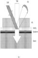
- Fig. 1 is a schematic diagram of an exemplary EMR delivery system suitable for performing real time temperature monitoring using a heatsink and one or more EMR responsive materials.
- the EMR delivery system may use a heatsink material or device such as for example, a sapphire heatsink that includes or works in conjunction with an EMR responsive material such as material that exhibits temperature dependent fluorescence or other detectable EMR changes, such as interference, wavelength shifting, phase changes and others.
- various exemplary tissues including the dermis (Derm) and epidermis (Epiderm) are shown. These and other tissues may be treated or otherwise energized or modified using EMR.
- Various tissues may be monitored for temperature changes using a signal generated in response to a change in one or more properties of an EMR responsive dopant or other material positioned relative to a target tissue region of interest.
- the disclosure relates to systems and methods of real time temperature monitoring through a heatsink with epidermis contact liquid / contact material that includes EMR responsive materials such as fluorescent nanoparticles or other materials or combinations as disclosed herein.
- a contact liquid, gel or other material that includes an EMR responsive material such as fluorescent nanoparticles is shown.
- This EMR responsive material or dopant for use with another material or as a layer is identified as FnPCL in Fig. 1 .
- a transparent heatsink HS is also shown.
- the heatsink HS may include sapphire or other EMR transmitting material.
- a region or layer of the HS may include EMR responsive material in lieu of the FnPCL or in addition to it.
- a first EMR source and a second EMR source are used to generate a first beam and a second beam.
- one EMR source is used in conjunction with a beam splitter and other optical elements to change an initial beam into a first beam and a second beam having different wavelengths.
- Fig. 2 is a schematic diagram of a system for directing EMR to tissue while simultaneously performing a real time temperature monitoring using a first EMR source and a second EMR source.
- various exemplary tissues including the dermis (Derm) and epidermis (Epiderm) are shown. These and other tissues may be treated or otherwise energized or modified using EMR.
- Various tissues may be monitored for temperature changes using a signal generated in response to a change in one or more properties of an EMR responsive dopant or other material positioned relative to a target tissue region of interest.
- real time temperature monitoring through a cold gel, topical, or other material that includes fluorescent EMR dopants such as nanoparticles may be used.
- the real time temperature monitoring is performed through a cold gel using temperature dependent fluorescence.
- a solution or gel containing fluorescent nanoparticles is shown as FnPG.
- one of the EMR beams is a treatment beam TxB and the other beam is an excitation beam ExB.
- the excitation beam ExB is a fluorescent excitation beam.
- the EMR delivery system also includes a signal detector FD.
- the signal detector FD may be operable to detect fluorescent signals such as those from the FnPG.
- the signal detector may be operable to detect other signals from EMR responsive dopants and materials.
- a signal conditioning optical system may be used as a separate system or may be combined or in optical or electrically communication with the signal detector FD.
- the fluorescence excitation beam it is preferable for the fluorescence excitation beam to irradiate the epidermal region, in thermal contact with the carrier containing the fluorescent nanoparticles, where the treatment beam enters the epidermis, as shown in the exemplary systems and methods depicted in Figs. 1 and 2 . That region will reach the highest epidermal temperature rise when compared to the surrounding epidermis not irradiated by the treatment beam.
- the measured highest temperature rise or other measurements or values obtained or derived from an EMR signal may be used to evaluate epidermal safety such as by performing real time tissue temperature monitoring.
- the EMR signal generated in response to incident EMR to one or more optically responsive elements is processed to obtain temperature information relative to tissue in thermal communication with the optically responsive element.
- the optically responsive element may include one or more fluorescent beads or particles such as nanoparticles, fluorophores, chromophores, or other dopants disposed on or in the cold gel or other optical transparent structure or cooling material or apparatus disclosed herein.
- rare-earth doped upconversion nanoparticles UCNPs
- the fluorescent nanoparticles irradiated by the excitation beam will emit one or more temperature dependent optical signals in all directions. A fraction of that optical signal will be captured by the fluorescent signal detector with its signal conditioning optical system, FD.
- the fluorescent signal can be monitored continuously, digitized as needed, and used to control the treatment beam delivery in real time to maintain epidermal safety.
- the excitation beam and treatment beam geometry outlined in exemplary embodiments depicted in Fig. 1 and Fig. 2 are only representative examples and do not exclude other embodiments.
- the excitation beam and treatment beam may be arranged coaxially or substantially coaxially.
- a wavelength or polarization based beam combiner may be used to deliver an excitation beam coaxially or substantially coaxially with the treatment beam such that tissue treatment and excitation or stimulation of EMR responsive dopants in optical path of such beams may be caused to fluoresce or undergo another optical or EMR transition such as an upconversion.
- methods of treating tissue and monitoring temperature may be performed simultaneously or substantially simultaneously.
- the fluorescent nanoparticles irradiated by the excitation beam, coaxial with the treatment beam, will emit one or more temperature dependent optical signals in all directions and a fraction of that optical signal will be captured by the fluorescent signal detector.
- a fluorescent material is selected so that the wavelength of the treatment beam makes it suitable also as a fluorescent excitation beam.
- Such modes of operation may be based on fluorescent emission following a single or double or multiple photon absorption or upconversion.
- the tissue damage in the epidermis can be correlated with an integral of the Arrhenius type process of damage accumulation as a function of the time spent at elevated temperature.
- the tissue damage in the epidermis can be evaluated in a clinical study with escalating fluence delivery and measurement of the peak epidermal temperature at the end of the pulse, or pulse sequence. Then the clinical evaluation of epidermis tissue damage at about 10 min, about 1 hour and about 24 hours post treatment can be correlated with the measured peak epidermal temperature and identify ranges of peak temperature rises that are safe and leave the epidermis with minimal or no tissue damage.
- the exemplary EMR delivery and temperature monitoring systems depicted in Figures 1 and 2 may use a single fluorescent detector to capture representative peak temperature in the epidermal region irradiated by the treatment beam and the excitation beam.
- a multichannel fluorescent detector like a CCD camera, can capture a 2D thermal map of the epidermal temperature in the treatment beam region and the surrounding area.
- Non-contact thermometers based on fluorescence or luminescence have been an ongoing area of development.
- the fluorescence light emission is affected by changes in the temperature in the surrounding medium. Changes in the fluorescence light emission are correlated with temperature changes in the tissue region being monitored.
- the tissue being treated heats up which heats the carrier materials (gel, solution, heatsink, other materials) that the EMR responsive dopants are in thermal communication with and thus operable to emit light correlated with tissue temperature changes.
- temperature changes may be measured using changes in one or more of the following parameters:
- a pair of selected transition intensities allows one to use the ratio of the two intensities for temperature monitoring. Taking the ratio of the two intensities approximately cancels out the transmission variations.
- the thin layer of water-based contact liquid between the skin and the cold sapphire will have an approximately uniform spatial temperature profile across its thickness. Its temperature will vary during the laser pulse delivery due to heat generation in the melanin layer in the epidermis and heat diffusion into the cold sapphire heat sink.
- a fluorescent material in the contact liquid can be illuminated by an excitation source such as an LED or continuous wave source with a preferred wavelength. Taking the ratio of two fluorescent line intensities may be used to perform the monitoring of the temperature of the contact liquid in real time.
- the temperature of epidermal melanin can be calculated based on the known thermal diffusivity of the contact liquid and the epidermis.
- the fluorescent material selected for the contact liquid or gel includes or substantially complies with one or more of the following properties or criteria for selection for temperature monitoring and other features and embodiments disclosed herein.
- Nd:YVO 4 and Nd:YALO 3 both have two line temperature dependent fluorescence in BW-II - between about 1000 and about 1350 nm.
- both materials are used for laser crystals with large absorption at pump wavelengths between about 790 to about 815 nm and that makes them unsuitable for fluorescence temperature measurements during laser treatment with about 800 nm laser.
- Cold gel combined with cold air cooling is used commercially in the Alexandrite and Nd:YAG hair removal lasers.
- Fluorescent temperature sensitive material can be added to the cold gel in contact with the skin.
- the cold gel layer applied to the skin surface before treatment is relatively thick on the order of about 1 mm to about 5 mm.
- Fluorescent material in the gel close to the epidermal surface will emit light representative of the epidermal temperature.
- Fluorescent material in the gel close to the external surface exposed to the flow of cold air will emit light representative of the much cooler air-gel boundary.
- a fluorescent material that increases its emission bandwidth of a single transition or shifts its spectrum as a function of the temperature increase would be suitable to produce fluorescent measurement representative of the highest temperature in the material.
- An example list of desired properties for a fluorescent material for the cold gel, heatsink, or other EMR responsive dopant includes:
- Nd:YALO 3 has temperature dependent fluorescence bandwidth in BW-I - between about 700 and about 950 nm. Unfortunately, the material has large absorption between about 750 and about 760 nm and that makes it unsuitable for fluorescence temperature measurements during laser treatment with the Alexandrite laser.
- a material that exhibits upconversion in response to EMR may be selected as an EMR responsive dopant alone or in combination with other EMR responsive dopants, carriers, and other materials.
- an upconversion based temperature dependent fluorescent material with negligible absorption in the treatment laser bands about 750 nm to about 765 nm, about 790 nm to about 815 nm and about 1040nm to about 1080 nm may be selected as an EMR responsive dopant in some embodiments.
- an exemplary EMR responsive dopant may include combinations of one or more of Ytterbium, Erbium, Sodium, and Yttrium, Fluoride, and Fluorine.
- the temperature dependent fluorescent material Ytterbium and Erbium doped Sodium yttrium fluoride, NaY 0.77 Yb 0.20 Er 0.03 F 4 has absorption and emission energy level diagram that is shown in Fig.3 .
- This material and variants thereof may be used as an EMR responsive dopant in various embodiments.
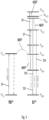
- an exemplary upconversion mechanism is shown for an EMR responsive dopant.
- the upconversion mechanism is shown for NaY 0.77 Yb 0.20 Er 0.03 F 4 , which undergoes difference luminescence transitions.
- Various non-radiative processes NRP are also shown by various curved or serpentine arrows. These arrows are labeled NRP in Fig. 3.
- Fig. 3 shows various state and wavelength transitions for exemplary EMR responsive dopants.
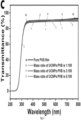
- next curve below the X curve is for the mass ratio of UCNPs:PVB of 3:100, which is plotted as Y(or blue).
- next curve below the Y curve is for the mass ratio of UCNPs:PVB of 5:100, which is plotted as Z (or green).
- the various plots of curves W, Z, Y, and Z show that the transmittance curve shifts below the pure PVB film as the ratio of UCNPs to PVB increases by mass.
- the plot shows that the addition NaY 0.77 Yb 0.20 Er 0.03 F 4 of in the form of UCNP (rare-earth doped upconversion nanoparticles) in variable concentrations leads to very small changes in the transmission of the pure PVB (polyvinyl butyral) film. That plot demonstrates that NaY 0.77 Yb 0.20 Er 0.03 F 4 has very low optical absorption in the wavelength range between 400 and 800nm.
- Other resins and optical films and materials may be used in various embodiments in addition or in lieu of PVB.
- Yb and Er are poor EMR absorbers in the wavelength range from about 800 to about 850nm and from about 1040 to about 1080 nm, which is not depicted in Fig. 4 . It is expected that Yb and Er would poorly absorb in the about 800 to about 850 nm and from about 1040 to about 1080 nm wavelength range even if these ions were present in a different formulation or environment. There is a band between about 850 nm and about 1040 nm where Yb and Er may absorb the excitation radiation, but Yb and Er still have very low absorption in the wavelength bands of specific interest for aesthetic treatments, for example, from about 790 to about 815 nm and from about 1040 to about 1080 nm.
- various wavelength ranges around about 980 nm may be used to pump EMR responsive dopants that include Yb and Er, either alone or together. Additional details and materials for selection as EMR-based dopant may be selected based on one or more of the criteria or requirements disclosed herein.
- the properties of NaY 0.77 Yb 0.20 Er 0.03 F 4 and its temperature dependent fluorescence ratios make it suitable for use as a fluorescent material in the relatively thin contact liquid or gel between a solid heat sink, like sapphire and the skin.
- NaY 0.77 Yb 0.20 Er 0.03 F 4 may be used as an EMR responsive dopant in various embodiments.
- NaY 0.77 Yb 0.20 Er 0.03 F 4 or other EMR responsive dopants may be included in a relatively thin layer of water based gel that is directly applied to the skin.
- the previously applied relatively thin gel layer that includes the EMR responsive dopant is coated with clear gel layer that does not include a fluorescent material or other EMR dopant.
- Multiple layers of gels, with and without EMR dopants, may be used in various combinations.
- the clear gel is applied as an overcoat.
- the application of the second layer thicker gel overcoat may be performed without intermixing the thin or initial gel layer containing the EMR dopant with a subsequent layer of gel or other material that does not include the EMR dopant.
- EMR dopants may be used without limitation such as a suitable temperature dependent fluorescence material or other material disclosed or identified herein.
- two gels are prepared as thin and thick patches that are sequentially applied on the skin before treatment. Further, in some embodiments using the application of two gels of differing thickness, viscosity, or other parameters, the thin first patch (or portion) to be applied contains the fluorescent material with temperature dependent fluorescence, and the second thicker patch (or portion) without fluorescent material provides extra heat sink mass.
- Suitable surface tissues that may be monitored by this system include external skin surfaces being treated for unwanted pigment, hair, vascular lesions, tattoos, and adipose tissue.
- Other surfaces that may be monitored by this system include mucosa for example, oral, vaginal, anal, nasal, and ophthalmic as well as eyelid and ear surface tissue.
- Other surfaces that may be monitored by this system include tissues accessible via surgery, either open or endoscopic surgery.
- a real time skin temperature monitoring system based on up-conversion materials emitting temperature dependent fluorescence may be adversely affected by the existing illumination in the operating room.
- the fluorescent material NaY 0.77 Yb 0.20 Er 0.03 F 4 has temperature dependent fluorescence emission bands in the green wavelength range of between about 525nm and about 540nm and in the red wavelength ranged of about 650nm.
- Incandescent or LED lights are often used to illuminate a treatment room and the operating field. With respect to both of these types of lights, the wavelength ranges used for illumination overlap with the fluorescent bands of the up-conversion materials that emit temperature dependence fluorescence that is used in certain light-based tissue treatments.
- wavelength bands can result in undesirable measurement errors by overlapping with the signal generated in response to the heating of fluorescent material being used for tissue temperature monitoring during a cosmetic or other tissue treatment.
- detecting a fluorescence based signal indicative of tissues or temperature changes may be washed out or otherwise combined with noise as a result of light being used to illuminate the room or a treatment region.
- the overlap of the room illumination with the temperature dependent fluorescence emission bands may lead to incorrectly calculated temperature or the inability to calculate a sufficiently accurate tissue temperature.
- the temperature is calculated from the ratio of the intensity of temperature dependent fluorescence emission bands that ratio will be affected by in band intensity added by the room lights.
- the room lights are not expected to produce biologically significant heating and temperature rise in the treatment area.
- a wavelength selective filter may be positioned relative to one or more optical components or applicators of a treatment head or applicator and a detector such as detector FD.
- a band pass filter can be positioned in front of the fluorescent optical detector in order to reduce, attenuate, and/or filter optical wavelengths from one or more lights that are outside of the fluorescent band(s) of interest.
- the use of such a filter may be configured such that wavelengths that are outside of the fluorescent band(s) of interest are modified to have a negligible intensity and thus limit their impact on any optical detectors used in a given cosmetic or monitoring system.
- a given wavelength filter is used to prevent out-of-band noise from reaching the optical detector of a treatment system.
- the fluorescent signal detector is disposed in a housing that prevents light from entering other than through an aperture this is disposed along a light path to receive the temperature dependent fluorescent emission that encodes tissue temperature information.
- the wavelength selection filter is disposed in front of, behind, or aligned with the aperture. The use of a housing and an aperture may be used to prevent the optical detector from being flooded with unfiltered light that overlaps with the temperature dependent fluorescent signal from the fluorescent material.
- the wavelength selective filter is tuned to a specific narrow wavelength band that is centered around or includes the wavelengths generated by the excitation of the fluorescent material.
- the room illumination that passes through the band pass filter in front of the fluorescent detector would represent a background noise signal that cannot be filtered optically. For example, that may happen if the room illumination has high intensity in the green and red bands mentioned above. Blocking the room illumination from reaching the treatment area would be a substantial inconvenience for the practitioner.
- Applicants have determined that systems and methods that reduce the impact of room illumination and other lights are preferably incorporated into a given monitoring or treatment system.
- Various embodiments avoid modifying room lights or including light blocking shields or coverings that are likely to interfere with an operator's ability to visually inspect a region being monitored or treated.
- the peak power of the temperature dependent fluorescence excitation laser is increased by a percentage or multiplier.
- the peak power of the laser or source of excitation energy is increased by a factor of about 10.
- a peak power per unit area for a fluorescence excitation source with wavelengths of about 980nm is less than about 100W/cm 2 .
- the peak power per unit area is less than about 50W/cm 2 .
- the peak power per unit area is less than about 20W/cm 2 .
- the peak power per unit area ranges from about 5 W/cm 2 to about 30 W/cm 2 .
- the peak power is increased while pulsing the laser or fluorescence excitation source with a low duty cycle.
- duty cycle is defined as the fraction of one period in which the source is active. The fraction is commonly expressed as percentage.
- a low duty cycle is less than about 40%. In some embodiments, a low duty cycle is less than about 20 %. In many embodiments, a low duty cycle is less than about 10%.
- a combination of an increase in peak power and a decrease in duty cycle may be selected so that the average excitation power stays low.
- a low average power per unit area for a fluorescence excitation source with wavelengths around 980nm is less than about 10W/cm 2 .
- a low average power per unit area is less than about 5W/cm 2 .
- a low average power per unit area is less than about than 2W/cm 2 .
- the low average power per unit area ranges from about 2 W/cm 2 to about 15 W/cm 2 .
- the choice for the average power per unit area for the fluorescence excitation source is selected in various embodiments such that it generates a biologically insignificant temperature rise in the treatment area.
- Additional design features may be used to adjust one or more parameters of the fluorescence excitation source or the temperature dependent fluorescence material. Specifically, various features and parameters may be modified if the higher power short fluorescence excitation pulses lead to saturation or bleaching of the up-conversion effect in the fluorescent material or fluorescent nano-particles or optical damage effects. For example, optical damage effects could be changes in the optical or fluorescent properties of the fluorescence material that may result in temperature calculation errors. In various embodiments, selecting the temperature dependent fluorescence material may address issues related to saturation or bleaching of the up-conversion effect or optical damage effects.
- the excitation laser power used in a temperature dependent fluorescence monitoring may range from about 1 to about 2 W/cm 2 .
- a higher power fluorescence excitation laser can be used to generate a larger temperature dependent fluorescence signal in pulse mode with low duty cycle to avoid unnecessary heating of the fluorescent material and the skin.
- the higher power fluorescence excitation laser may lead to a higher fluorescent signal.
- the low duty cycle of the fluorescence excitation laser is selected to produce biologically insignificant heating. In turn, this limits the temperature rise in the treatment area.
- a fluorescence excitation laser having a power that ranges from about 10 W/cm 2 to about 20 W/cm 2 excitation laser system may be used in some embodiments.
- the fluorescence excitation laser is pulsed with on-time of up to 40ms at a rep-rate up to 2Hz (these are typical values for an example application of laser hair removal and lead to up to 8% duty cycle for the irradiation laser).
- the pulse on-time or pulse duration of the fluorescence excitation laser may be chosen to start shortly before the delivery of the treatment laser pulse so that a baseline temperature can be measured immediately before the treatment pulse. After the baseline temperature reading, the fluorescence excitation laser energizes the fluorescent material for the duration of the treatment pulse. In this way, the use of the excitation light during a given monitoring or treatment session provides real-time temperature measurement over the course of a given session.
- temperature measurements may be improved by extracting the temperature dependent fluorescent signal from the room illumination noise with the use of one or more signal processing devices.
- a lock-in amplifier may be used.
- a lock-in amplifier allows the extraction of a useful weak signal from a large noise background.
- a lock-in amplifier takes the input signal from the fluorescence signal detector, multiplies it by the synchronous reference signal, and integrates it over a specified time period.
- the reference signal is provided from the fluorescence excitation laser or its driver or its optical modulator.
- the resulting output signal is a DC signal.
- One advantage of using a lock-in amplifier is that the contribution from an input signal that is not at the same frequency as the synchronous reference signal, e.g. the room lights, is attenuated close to zero.
- the lock-in amplifier allows the low intensity temperature dependent fluorescent signal to be measured against the background of the room lights noise signal. By reducing the noise contribution of the room lights, the lock-in amplifier increases the signal to noise ratio of the temperature dependent fluorescent signal. In turn, this improves the accuracy of temperature readings obtained using the fluorescent signal.
- the specified time period over which the integration is performed ranges from about 1 milliseconds to about 1000 milliseconds.
- the system includes a phase-locked loop (PLL) that locks to the reference frequency and supplies the reference frequency to the lock-in amplifier.
- the lock-in amplifier includes a multiplier, a phase-sensitive detector, one or more filters, an integrator, and various other components.
- a low pass filter or other filter is used to remove various noise frequencies that are not associated with the reference frequency.
- the lock-in amplifier multiples the fluorescent light signal that is correlated with skin temperature with sine wave and measures the Fourier component of the signal at the reference frequency.
- FIG. 5 An example block-diagram of a system that includes a control system and a fluorescent signal detection (FSD) system is shown in Fig. 5 .
- the FSD system includes detector FD and a lock-in amplifier.
- the control system triggers the fluorescent excitation source to activate the fluorescence excitation beam with a modulation frequency f m .
- the modulation frequency is supplied also to the FSD system as a synchronous reference input to the lock-in amplifier.
- the range of modulation frequencies, f m for pulsing the fluorescence excitation source is from about 100Hz and to about 100MHz.
- f m ranges from about 100Hz to about 100kHz.
- the FSD system determines the pre-treatment skin temperature using the lock-in amplifier, the temperature dependent fluorescent signal and the signal modulated using the modulation frequency f m .
- the FSD system sends the pre-treatment skin temperature data to the control system. If the control system determines that the pre-treatment skin temperature is within the expected range, the treatment beam source is activated for a pre-set period of time. During delivery of the treatment beam, the FSD system continuously monitors and determines the skin temperature. Real time skin temperature values or the underlying data are obtained and transmitted to the control system. In various embodiments, the control system uses or determines changes in temperature measured using signals received from the fluorescent material to generate various responsive outputs.
- control system may alert the operator with visual, sensory, or auditory alerts.
- control system may stop delivery of the treatment beam in response to one or more temperature values, thresholds or ranges that are correlated with fluorescent signals from the FnPg layer.
- luminescence thermometry may be used along with various compounds and materials as described herein. These compounds and materials may be selected based on changes in intensity, linewidth, photoluminescence lifetime, or spectral shifts.
- lanthanide ions are used in the various temperature sensing applications described herein because of their stability and narrow spectral features that enable distinguishing changes easily.
- Lanthanide-doped materials display upconversion luminescence: they can be excited with near-infrared (NIR) light, and emit in the visible region of the spectrum. NIR excitation induces less self-absorption and scattering by biological tissue; therefore remote excitation is easier.
- NIR near-infrared
- inorganic nanoparticles doped with lanthanide ions, and others may be used as cream, topical, or otherwise applied to a subject.
- Materials that include a lanthanide-doped phosphor such as NaY 0.77 Yb 0.20 Er 0.03 F 4 and others may be used to perform luminescence thermometry and used as a component in the gels, creams, layers, and other materials disclosed herein.
- two or more 980 nm photons are used to induce emission in the visible.
- direct excitation of the Er 3+ ion there is energy transfer from excited Yb 3+ to excited states of Er 3+ .
- Emission is in the blue, green and red regions of the visible spectrum depending on the upper Er 3+ level in the transition. Upconversion thermometry often focuses on the two transitions emitting at 525 nm and 540 nm, i.e.
- N i N S C exp ⁇ ⁇ E kT
- N i the population in level i
- ⁇ E the spacing between the levels
- k the Boltzmann's constant
- C is a constant depending on degeneracies.
- the ratio of 525 nm and 540 nm luminescence intensities, RHS can be used to infer the ratio of 2 H 11/2 to 4 S 3/2 , which gives the temperature of the sample.
- temperature-dependent upconversion luminescence results for NaY 0.77 Yb 0.20 Er 0.03 F 4 may be obtained using a spectrometer coupled to a temperature stage.
- each intervening value between the upper and lower limits of that range or list of values is individually contemplated and is encompassed within the disclosure as if each value were specifically enumerated.
- smaller ranges between and including the upper and lower limits of a range are contemplated and encompassed within the disclosure.
- Listing exemplary values or ranges is not a disclaimer of other values or ranges between and including the upper and lower limits of a range.
Landscapes
- Health & Medical Sciences (AREA)
- Life Sciences & Earth Sciences (AREA)
- Physics & Mathematics (AREA)
- Surgery (AREA)
- Veterinary Medicine (AREA)
- General Health & Medical Sciences (AREA)
- Engineering & Computer Science (AREA)
- Biomedical Technology (AREA)
- Heart & Thoracic Surgery (AREA)
- Medical Informatics (AREA)
- Molecular Biology (AREA)
- Public Health (AREA)
- Animal Behavior & Ethology (AREA)
- Optics & Photonics (AREA)
- Pathology (AREA)
- Biophysics (AREA)
- Electromagnetism (AREA)
- Nuclear Medicine, Radiotherapy & Molecular Imaging (AREA)
- Otolaryngology (AREA)
- Dermatology (AREA)
- Investigating, Analyzing Materials By Fluorescence Or Luminescence (AREA)
- Measuring And Recording Apparatus For Diagnosis (AREA)
- Radiation Pyrometers (AREA)
Claims (15)
- Elektromagnetische Strahlung, EMR, abgebendes Überwachungssystem zur nichtinvasiven Temperaturüberwachung an Oberflächengewebe mit Folgendem:einer ersten Quelle für EMR mit einem ersten Wellenlängenbereich,einer zweiten Quelle für EMR mit einem zweiten Wellenlängenbereich undeinem Material für den Gewebekontakt, das eine Reihe von wellenlängenbereichsspezifischen, auf EMR reagierenden Dotierstoffen umfasst,wobei das Material für den Gewebekontakt dafür ausgelegt ist, auf eine Oberfläche einer Gewebe-Zielregion angeordnet zu werden,wobei das Material für den Gewebekontakt dafür ausgelegt ist, aus der ersten Quelle EMR in einer ersten Ausrichtung zu empfangen, undwobei das Material für den Gewebekontakt dafür ausgelegt ist, aus der zweiten Quelle EMR in einer zweiten Ausrichtung zu empfangen.
- System nach Anspruch 1, wobei sich die erste und die zweite Ausrichtung gleichen.
- System nach Anspruch 1, wobei die zweite Ausrichtung in einem Winkel zur ersten Ausrichtung liegt.
- System nach Anspruch 1, wobei die erste EMR-Quelle dafür ausgelegt ist, einen Behandlungsstrahl zu erzeugen.
- System nach Anspruch 4, wobei die zweite EMR-Quelle dafür ausgelegt ist, einen Anregungsstrahl zu erzeugen.
- System nach Anspruch 1, wobei die zweite EMR-Quelle dazu dient, einen oder mehrere zusätzliche Wellenlängenbereiche zu transmittieren.
- System nach Anspruch 1, wobei die auf EMR reagierenden Dotierstoffe aus der Gruppe ausgewählt sind, die aus einem Partikel, einem Kügelchen, einer Schicht, einem Dünnfilm, einem fluoreszierenden Material, einem fluoreszierenden Nanopartikel, einem fluoreszierenden Upconversion-Nanopartikel, einem Upconversion-Material, einem Nanopartikel, einem Chromophor, einem streuenden Element, einem lichtbrechenden Element, einem wellenlängenverschiebenden Material oder einer wellenlängenverschiebenden Vorrichtung, einem Interferenzgenerator, einem Absorber und Kombinationen daraus besteht.
- System nach Anspruch 1, wobei die auf EMR reagierenden Dotierstoffe zwei oder mehrere fluoreszierende Materialien umfassen.
- System nach Anspruch 1, das ferner einen Signaldetektor umfasst, wobei der Signaldetektor so angeordnet ist, dass er temperaturabhängige EMR empfängt, die von einem oder mehreren der Dotierstoffe erzeugt wird,
wobei das System ferner einen Signalprozessor umfasst, wobei der Signalprozessor dazu dient, mithilfe empfangener temperaturabhängiger EMR von einem oder mehreren Dotierstoffen und eines oder mehrerer Parameter der von der zweiten EMR-Quelle erzeugten EMR Temperaturänderungen zu messen. - System nach Anspruch 1, wobei die auf EMR reagierenden Dotierstoffe temperaturempfindlich sind, so dass Veränderungen der Gewebetemperatur zu Veränderungen von von den Dotierstoffen emittierter oder transmittierter EMR führen.
- System nach Anspruch 9, das ferner ein Steuersystem umfasst, das dazu dient, eine Behandlung zu stoppen oder eine Warnung zu erzeugen, wenn mithilfe von EMR von den Dotierstoffen eine Gewebetemperatur erkannt wird, die einen Schwellenwert oder vorgegebenen Wert übersteigt.
- System nach Anspruch 9, das ferner vor dem Detektor einen wellenlängenselektiven Filter umfasst, der dafür ausgelegt ist, einen oder mehrere Wellenlängenbereiche von Raum- oder Behandlungsstrahlung herauszufiltern, während er die von einem oder mehreren der Dotierstoffe erzeugte temperaturabhängige EMR transmittiert.
- System nach Anspruch 1, wobei die zweite EMR-Quelle dafür ausgelegt ist, einen Anregungsstrahl zu erzeugen, wobei der Anregungsstrahl eine Modulationsfrequenz f m aufweist.
- System nach Anspruch 23 [sic], das ferner einen Lock-in-Verstärker mit einer Referenzfrequenz umfasst, wobei die Referenzfrequenz die Modulationsfrequenz f m ist.
- System nach Anspruch 1, wobei die zweite EMR-Quelle dafür ausgelegt ist, einen gepulsten Anregungsstrahl zu erzeugen, und die erste EMR-Quelle dafür ausgelegt ist, einen Behandlungsstrahl zu erzeugen.
Priority Applications (1)
| Application Number | Priority Date | Filing Date | Title |
|---|---|---|---|
| EP25163968.8A EP4552560A3 (de) | 2021-04-27 | 2022-04-27 | Vorrichtung zur kontaktlosen echtzeit-hauttemperaturmessung |
Applications Claiming Priority (3)
| Application Number | Priority Date | Filing Date | Title |
|---|---|---|---|
| US202163180454P | 2021-04-27 | 2021-04-27 | |
| US202163280733P | 2021-11-18 | 2021-11-18 | |
| PCT/US2022/026460 WO2022232220A1 (en) | 2021-04-27 | 2022-04-27 | Device for real-time non-contact skin temperature measurement |
Related Child Applications (1)
| Application Number | Title | Priority Date | Filing Date |
|---|---|---|---|
| EP25163968.8A Division EP4552560A3 (de) | 2021-04-27 | 2022-04-27 | Vorrichtung zur kontaktlosen echtzeit-hauttemperaturmessung |
Publications (3)
| Publication Number | Publication Date |
|---|---|
| EP4329657A1 EP4329657A1 (de) | 2024-03-06 |
| EP4329657B1 true EP4329657B1 (de) | 2025-03-19 |
| EP4329657C0 EP4329657C0 (de) | 2025-03-19 |
Family
ID=81655004
Family Applications (2)
| Application Number | Title | Priority Date | Filing Date |
|---|---|---|---|
| EP22723897.9A Active EP4329657B1 (de) | 2021-04-27 | 2022-04-27 | Vorrichtung zur kontaktlosen echtzeit-hauttemperaturmessung |
| EP25163968.8A Pending EP4552560A3 (de) | 2021-04-27 | 2022-04-27 | Vorrichtung zur kontaktlosen echtzeit-hauttemperaturmessung |
Family Applications After (1)
| Application Number | Title | Priority Date | Filing Date |
|---|---|---|---|
| EP25163968.8A Pending EP4552560A3 (de) | 2021-04-27 | 2022-04-27 | Vorrichtung zur kontaktlosen echtzeit-hauttemperaturmessung |
Country Status (3)
| Country | Link |
|---|---|
| US (1) | US20240197397A1 (de) |
| EP (2) | EP4329657B1 (de) |
| WO (1) | WO2022232220A1 (de) |
Family Cites Families (18)
| Publication number | Priority date | Publication date | Assignee | Title |
|---|---|---|---|---|
| US3335716A (en) * | 1965-01-18 | 1967-08-15 | Gen Electric | Diagnostic thermography method and means |
| EP0991372B1 (de) * | 1997-05-15 | 2004-08-04 | Palomar Medical Technologies, Inc. | Gerät zur dermatologischen behandlung |
| JP2001004460A (ja) * | 1999-06-25 | 2001-01-12 | Osaka Gas Co Ltd | 温度測定方法及び温度測定装置及び感温塗料 |
| US6503269B2 (en) * | 2000-06-12 | 2003-01-07 | Scott A. Nield | Method of treating intervertebral discs using optical energy and optical temperature feedback |
| US20090069741A1 (en) * | 2004-04-09 | 2009-03-12 | Palomar Medical Technologies, Inc. | Methods And Devices For Fractional Ablation Of Tissue For Substance Delivery |
| WO2007035444A2 (en) * | 2005-09-15 | 2007-03-29 | Palomar Medical Technologies, Inc. | Skin optical characterization device |
| CN103479427B (zh) * | 2008-03-11 | 2016-11-23 | 莎责有限公司 | 皮肤病治疗设备 |
| US20130096546A1 (en) * | 2009-03-05 | 2013-04-18 | Cynosure, Inc. | Non-uniform beam optical treatment methods and systems |
| US20120283575A1 (en) * | 2009-10-09 | 2012-11-08 | Govind Rao | Remote non-invasive parameter sensing system and method |
| US9560974B2 (en) * | 2011-06-29 | 2017-02-07 | University Of Maryland Baltimore County | Luminescence based noninvasive remote parameter sensor and sensing method |
| US9653935B2 (en) * | 2012-04-20 | 2017-05-16 | Medtronic, Inc. | Sensing temperature within medical devices |
| US9370392B2 (en) * | 2012-10-02 | 2016-06-21 | Covidien Lp | Heat-sensitive optical probes |
| WO2016108071A1 (en) * | 2014-12-30 | 2016-07-07 | Nexus Ekspertyzy I Badania Dr Jacek Stepien | Contact thermo-optical structure and its application for non-invasive imaging of histamine-induced hyperthermal subcutaneous reaction magnitude in cutaneous allergic reaction, recording device and method of allergic reaction diagnosis |
| US20220401750A1 (en) * | 2016-11-22 | 2022-12-22 | Dominion Aesthetic Technologies, Inc. | Systems and methods for aesthetic treatment |
| BR112020026163A2 (pt) * | 2018-06-22 | 2021-03-23 | Avava, Inc. | detecção de realimentação para um dispositivo de tratamento |
| CN109405996B (zh) * | 2018-10-17 | 2021-01-08 | 京东方科技集团股份有限公司 | 一种温度计及其控制方法 |
| KR20220024048A (ko) * | 2019-05-14 | 2022-03-03 | 더 보드 오브 리젠츠 오브 더 유니버시티 오브 텍사스 시스템 | 고속 및 고종횡비 레이저 절삭 재료 가공을 위한 방법 및 장치 |
| US11684799B2 (en) * | 2021-08-28 | 2023-06-27 | Cutera, Inc. | Image guided laser therapy |
-
2022
- 2022-04-27 EP EP22723897.9A patent/EP4329657B1/de active Active
- 2022-04-27 EP EP25163968.8A patent/EP4552560A3/de active Pending
- 2022-04-27 WO PCT/US2022/026460 patent/WO2022232220A1/en not_active Ceased
- 2022-04-27 US US18/288,138 patent/US20240197397A1/en active Pending
Also Published As
| Publication number | Publication date |
|---|---|
| EP4552560A2 (de) | 2025-05-14 |
| EP4552560A3 (de) | 2025-06-25 |
| WO2022232220A1 (en) | 2022-11-03 |
| EP4329657A1 (de) | 2024-03-06 |
| US20240197397A1 (en) | 2024-06-20 |
| EP4329657C0 (de) | 2025-03-19 |
Similar Documents
| Publication | Publication Date | Title |
|---|---|---|
| EP2624777B1 (de) | Vorrichtung für eine hautkrebs-wärmetherapie | |
| US7208007B2 (en) | System and method utilizing guided fluorescence for high intensity applications | |
| US20080033300A1 (en) | Systems and methods for monitoring temperature during electrosurgery or laser therapy | |
| US20220409275A1 (en) | Surgical laser system | |
| RU2765091C1 (ru) | Процесс определения и прогнозное управление с обратной связью дозиметрией с использованием измерения температуры поверхности кожи и соответствующие способы | |
| EP1320333B1 (de) | Hautbehandlungsvorrichting und methode dafür | |
| EP1665996A2 (de) | Vorrichtung und Verfahren zur photokosmetischen und photodermatologischen Behandlung | |
| US20060271028A1 (en) | Dermatological treatment device | |
| US9931519B2 (en) | Medical apparatus, therapy apparatus, method of estimating optical probe, and calibration method | |
| US20050049658A1 (en) | System and method for heating skin using light to provide tissue treatment | |
| WO1998055180A1 (en) | Method and apparatus for causing rapid and deep spatially selective coagulation during thermally mediated therapeutic procedures | |
| US20030036749A1 (en) | Method of treating disorders associated with sebaceous follicles | |
| US10888376B2 (en) | Surgical laser system | |
| Kamanli et al. | Development of a new multi-mode NIR laser system for photodynamic therapy | |
| Lukač et al. | Influence of tissue desiccation on critical temperature for thermal damage during Er: YAG laser skin treatments | |
| EP4552560A2 (de) | Vorrichtung zur kontaktlosen echtzeit-hauttemperaturmessung | |
| GB2381752A (en) | Laser skin treatment device with control means dependent on a sensed property of the skin to be treated | |
| Anvari et al. | Dynamic epidermal cooling in conjunction with laser treatment of port-wine stains: theoretical and preliminary clinical evaluations | |
| RU120008U1 (ru) | Устройство для контактного облучения с системой охлаждения | |
| Brown | Fundamentals of lasers and light devices in dermatology | |
| KR20160101227A (ko) | 테라헤르츠파를 이용한 광열치료 온도 제어 장치 및 그 제어 방법 | |
| US12603470B2 (en) | Apparatus and method for emitting multi-wavelength laser | |
| WO2012118862A2 (en) | Fluorescent handpiece | |
| Masters | Variation of Fluorescence with Temperature in Human Tissue | |
| RU2785336C2 (ru) | Системы и способы предварительного кондиционирования для создания термического градиента с целью селективного фототермического таргетирования |
Legal Events
| Date | Code | Title | Description |
|---|---|---|---|
| STAA | Information on the status of an ep patent application or granted ep patent |
Free format text: STATUS: UNKNOWN |
|
| STAA | Information on the status of an ep patent application or granted ep patent |
Free format text: STATUS: THE INTERNATIONAL PUBLICATION HAS BEEN MADE |
|
| PUAI | Public reference made under article 153(3) epc to a published international application that has entered the european phase |
Free format text: ORIGINAL CODE: 0009012 |
|
| STAA | Information on the status of an ep patent application or granted ep patent |
Free format text: STATUS: REQUEST FOR EXAMINATION WAS MADE |
|
| 17P | Request for examination filed |
Effective date: 20231122 |
|
| AK | Designated contracting states |
Kind code of ref document: A1 Designated state(s): AL AT BE BG CH CY CZ DE DK EE ES FI FR GB GR HR HU IE IS IT LI LT LU LV MC MK MT NL NO PL PT RO RS SE SI SK SM TR |
|
| DAV | Request for validation of the european patent (deleted) | ||
| DAX | Request for extension of the european patent (deleted) | ||
| GRAP | Despatch of communication of intention to grant a patent |
Free format text: ORIGINAL CODE: EPIDOSNIGR1 |
|
| STAA | Information on the status of an ep patent application or granted ep patent |
Free format text: STATUS: GRANT OF PATENT IS INTENDED |
|
| INTG | Intention to grant announced |
Effective date: 20241010 |
|
| GRAS | Grant fee paid |
Free format text: ORIGINAL CODE: EPIDOSNIGR3 |
|
| GRAA | (expected) grant |
Free format text: ORIGINAL CODE: 0009210 |
|
| STAA | Information on the status of an ep patent application or granted ep patent |
Free format text: STATUS: THE PATENT HAS BEEN GRANTED |
|
| AK | Designated contracting states |
Kind code of ref document: B1 Designated state(s): AL AT BE BG CH CY CZ DE DK EE ES FI FR GB GR HR HU IE IS IT LI LT LU LV MC MK MT NL NO PL PT RO RS SE SI SK SM TR |
|
| REG | Reference to a national code |
Ref country code: GB Ref legal event code: FG4D |
|
| REG | Reference to a national code |
Ref country code: CH Ref legal event code: EP |
|
| REG | Reference to a national code |
Ref country code: IE Ref legal event code: FG4D |
|
| REG | Reference to a national code |
Ref country code: DE Ref legal event code: R096 Ref document number: 602022012007 Country of ref document: DE |
|
| U01 | Request for unitary effect filed |
Effective date: 20250417 |
|
| U07 | Unitary effect registered |
Designated state(s): AT BE BG DE DK EE FI FR IT LT LU LV MT NL PT RO SE SI Effective date: 20250424 |
|
| U20 | Renewal fee for the european patent with unitary effect paid |
Year of fee payment: 4 Effective date: 20250428 |
|
| PG25 | Lapsed in a contracting state [announced via postgrant information from national office to epo] |
Ref country code: RS Free format text: LAPSE BECAUSE OF FAILURE TO SUBMIT A TRANSLATION OF THE DESCRIPTION OR TO PAY THE FEE WITHIN THE PRESCRIBED TIME-LIMIT Effective date: 20250619 |
|
| PG25 | Lapsed in a contracting state [announced via postgrant information from national office to epo] |
Ref country code: NO Free format text: LAPSE BECAUSE OF FAILURE TO SUBMIT A TRANSLATION OF THE DESCRIPTION OR TO PAY THE FEE WITHIN THE PRESCRIBED TIME-LIMIT Effective date: 20250619 |
|
| PG25 | Lapsed in a contracting state [announced via postgrant information from national office to epo] |
Ref country code: HR Free format text: LAPSE BECAUSE OF FAILURE TO SUBMIT A TRANSLATION OF THE DESCRIPTION OR TO PAY THE FEE WITHIN THE PRESCRIBED TIME-LIMIT Effective date: 20250319 |
|
| PG25 | Lapsed in a contracting state [announced via postgrant information from national office to epo] |
Ref country code: GR Free format text: LAPSE BECAUSE OF FAILURE TO SUBMIT A TRANSLATION OF THE DESCRIPTION OR TO PAY THE FEE WITHIN THE PRESCRIBED TIME-LIMIT Effective date: 20250620 |
|
| PG25 | Lapsed in a contracting state [announced via postgrant information from national office to epo] |
Ref country code: SM Free format text: LAPSE BECAUSE OF FAILURE TO SUBMIT A TRANSLATION OF THE DESCRIPTION OR TO PAY THE FEE WITHIN THE PRESCRIBED TIME-LIMIT Effective date: 20250319 |
|
| PG25 | Lapsed in a contracting state [announced via postgrant information from national office to epo] |
Ref country code: ES Free format text: LAPSE BECAUSE OF FAILURE TO SUBMIT A TRANSLATION OF THE DESCRIPTION OR TO PAY THE FEE WITHIN THE PRESCRIBED TIME-LIMIT Effective date: 20250319 |
|
| PG25 | Lapsed in a contracting state [announced via postgrant information from national office to epo] |
Ref country code: PL Free format text: LAPSE BECAUSE OF FAILURE TO SUBMIT A TRANSLATION OF THE DESCRIPTION OR TO PAY THE FEE WITHIN THE PRESCRIBED TIME-LIMIT Effective date: 20250319 |
|
| PG25 | Lapsed in a contracting state [announced via postgrant information from national office to epo] |
Ref country code: CZ Free format text: LAPSE BECAUSE OF FAILURE TO SUBMIT A TRANSLATION OF THE DESCRIPTION OR TO PAY THE FEE WITHIN THE PRESCRIBED TIME-LIMIT Effective date: 20250319 |
|
| PG25 | Lapsed in a contracting state [announced via postgrant information from national office to epo] |
Ref country code: SK Free format text: LAPSE BECAUSE OF FAILURE TO SUBMIT A TRANSLATION OF THE DESCRIPTION OR TO PAY THE FEE WITHIN THE PRESCRIBED TIME-LIMIT Effective date: 20250319 |
|
| PG25 | Lapsed in a contracting state [announced via postgrant information from national office to epo] |
Ref country code: IS Free format text: LAPSE BECAUSE OF FAILURE TO SUBMIT A TRANSLATION OF THE DESCRIPTION OR TO PAY THE FEE WITHIN THE PRESCRIBED TIME-LIMIT Effective date: 20250719 |
|
| REG | Reference to a national code |
Ref country code: CH Ref legal event code: H13 Free format text: ST27 STATUS EVENT CODE: U-0-0-H10-H13 (AS PROVIDED BY THE NATIONAL OFFICE) Effective date: 20251125 |
|
| PG25 | Lapsed in a contracting state [announced via postgrant information from national office to epo] |
Ref country code: MC Free format text: LAPSE BECAUSE OF FAILURE TO SUBMIT A TRANSLATION OF THE DESCRIPTION OR TO PAY THE FEE WITHIN THE PRESCRIBED TIME-LIMIT Effective date: 20250319 |
|
| PG25 | Lapsed in a contracting state [announced via postgrant information from national office to epo] |
Ref country code: CH Free format text: LAPSE BECAUSE OF NON-PAYMENT OF DUE FEES Effective date: 20250430 |
|
| PLBE | No opposition filed within time limit |
Free format text: ORIGINAL CODE: 0009261 |
|
| STAA | Information on the status of an ep patent application or granted ep patent |
Free format text: STATUS: NO OPPOSITION FILED WITHIN TIME LIMIT |
|
| REG | Reference to a national code |
Ref country code: CH Ref legal event code: L10 Free format text: ST27 STATUS EVENT CODE: U-0-0-L10-L00 (AS PROVIDED BY THE NATIONAL OFFICE) Effective date: 20260128 |
|
| 26N | No opposition filed |
Effective date: 20251222 |
|
| PG25 | Lapsed in a contracting state [announced via postgrant information from national office to epo] |
Ref country code: IE Free format text: LAPSE BECAUSE OF NON-PAYMENT OF DUE FEES Effective date: 20250427 |