EP4329468B1 - Vorrichtung und verfahren zur kontrolle der geschwindigkeit und richtung eines lateralen förderers eines landwirtschaftlichen erntevorsatzes - Google Patents
Vorrichtung und verfahren zur kontrolle der geschwindigkeit und richtung eines lateralen förderers eines landwirtschaftlichen erntevorsatzes Download PDFInfo
- Publication number
- EP4329468B1 EP4329468B1 EP22724300.3A EP22724300A EP4329468B1 EP 4329468 B1 EP4329468 B1 EP 4329468B1 EP 22724300 A EP22724300 A EP 22724300A EP 4329468 B1 EP4329468 B1 EP 4329468B1
- Authority
- EP
- European Patent Office
- Prior art keywords
- vehicle
- speed
- agricultural
- input
- lateral
- Prior art date
- Legal status (The legal status is an assumption and is not a legal conclusion. Google has not performed a legal analysis and makes no representation as to the accuracy of the status listed.)
- Active
Links
Images


Classifications
-
- A—HUMAN NECESSITIES
- A01—AGRICULTURE; FORESTRY; ANIMAL HUSBANDRY; HUNTING; TRAPPING; FISHING
- A01D—HARVESTING; MOWING
- A01D41/00—Combines, i.e. harvesters or mowers combined with threshing devices
- A01D41/12—Details of combines
- A01D41/127—Control or measuring arrangements specially adapted for combines
- A01D41/1274—Control or measuring arrangements specially adapted for combines for drives
-
- A—HUMAN NECESSITIES
- A01—AGRICULTURE; FORESTRY; ANIMAL HUSBANDRY; HUNTING; TRAPPING; FISHING
- A01D—HARVESTING; MOWING
- A01D41/00—Combines, i.e. harvesters or mowers combined with threshing devices
- A01D41/12—Details of combines
- A01D41/14—Mowing tables
- A01D41/141—Automatic header control
-
- A—HUMAN NECESSITIES
- A01—AGRICULTURE; FORESTRY; ANIMAL HUSBANDRY; HUNTING; TRAPPING; FISHING
- A01D—HARVESTING; MOWING
- A01D41/00—Combines, i.e. harvesters or mowers combined with threshing devices
- A01D41/12—Details of combines
- A01D41/14—Mowing tables
- A01D41/142—Header drives
-
- A—HUMAN NECESSITIES
- A01—AGRICULTURE; FORESTRY; ANIMAL HUSBANDRY; HUNTING; TRAPPING; FISHING
- A01D—HARVESTING; MOWING
- A01D75/00—Accessories for harvesters or mowers
- A01D75/18—Safety devices for parts of the machines
- A01D75/182—Avoiding overload
Definitions
- the present disclosure relates generally to an agricultural header and, more specifically, to controlling a speed and direction of a lateral conveyor of an agricultural header.
- a harvester may be used to harvest crops, such as barley, beans, beets, carrots, corn, cotton, flax, oats, potatoes, rye, soybeans, wheat, or other plant crops.
- crops such as barley, beans, beets, carrots, corn, cotton, flax, oats, potatoes, rye, soybeans, wheat, or other plant crops.
- the harvesting process may begin by removing a portion of a plant from a field using a header of the harvester.
- the header may cut the plant and transport the cut crops to a processing system of the harvester.
- Certain headers include a cutter bar assembly configured to cut a portion of each crop (e.g., a stalk), thereby separating the cut crop from the soil.
- the cutter bar assembly may extend along a substantial portion of a width of the header at a forward end of the header.
- the header may also include one or more conveyors (e.g., belts) positioned behind the cutter bar assembly relative to a direction of travel of the harvester.
- the belt(s) are configured to transport the cut crops to an inlet (e.g., central inlet) of the processing system.
- an inlet e.g., central inlet
- lateral belts laterally transport cut crops towards a centrally located infeed belt that transports the crop rearward into the harvester's feeder.
- Certain headers may also include a reel assembly, which may include a reel having multiple fingers extending from a central framework.
- the central framework is driven to rotate, such that the fingers move in a circular pattern.
- the fingers are configured to engage the crops, thereby preparing the crops to be cut by the cutter bar assembly and/or urging the cut crops to move toward the belt(s).
- a large slug of crop can feed onto the center section and lodge itself there or between the lateral belts and the infeed belt.
- an operator operates the harvester in a "de-slug” mode where all of the belts (lateral belts and infeed belt) are reversed in direction and the reel may also be reversed.
- this "de-slug” mode is time consuming since the entire threshing system of the harvester needs to be slowed to a stop before reversing directions.
- an agricultural system includes a header.
- the header includes a frame, a first lateral conveyor coupled to the frame, and a second lateral conveyor coupled to the frame.
- the first and second lateral conveyors are configured to laterally transport crop material towards a central crop-receiving aperture in a first direction.
- the header also includes actuators configured to adjust a speed and a direction of the first and second lateral conveyors.
- the agricultural system also includes a controller configured to receive an input from an input device that causes the controller to automatically link the speed and the direction of the first and second lateral conveyors to a vehicle speed and a vehicle direction of an agricultural vehicle that the header is coupled to.
- the controller is also configured to provide, when receiving the input, a control signal to the actuators that alters the speed and the direction of the first and second lateral conveyors in response to changes in the vehicle speed and the vehicle direction.
- a method for operating lateral conveyors on a header of an agricultural vehicle includes receiving an input from an input device that causes a controller to automatically link a speed and a direction of both a first lateral conveyor and a second lateral conveyor to a vehicle speed and a vehicle direction of the agricultural vehicle.
- the first and second lateral conveyors are coupled to a frame of the header and are configured to laterally transport crop material towards a central crop-receiving aperture in a first direction.
- the method also includes providing, when receiving the input, a control signal to actuators coupled to the first and second lateral conveyors that alters the speed and the direction of the first and second lateral conveyors in response to changes in the vehicle speed and the vehicle direction.
- a non-transitory computer readable medium includes executable instructions that, when executed by a processor, are configured to cause the processor to perform acts.
- the acts include receiving an input from an input device to automatically link a speed and a direction of both a first lateral conveyor and a second lateral conveyor to a vehicle speed and a vehicle direction of an agricultural vehicle.
- the first and second lateral conveyors are coupled to a frame of a header coupled to the agricultural vehicle and the first and second lateral conveyors are configured to laterally transport crop material towards a central crop-receiving aperture in the first direction.
- the acts also include providing, when receiving the input, a control signal to actuators coupled to the first and the second lateral conveyors that alters the speed and the direction of the first and second lateral conveyors in response to changes in the vehicle speed and the vehicle direction.
- the process of farming typically begins with planting seeds within a field. Over time, the seeds grow and eventually become harvestable crops. Typically, only a portion of each crop is commercially valuable, so each crop is harvested to separate the usable material from the remainder of the crop.
- a harvester may cut agricultural crops within a field via a header.
- the header may also gather the cut agricultural crops into a processing system of the harvester for further processing.
- the processing system may include a threshing machine configured to thresh the agricultural crops, thereby separating the crops into certain desired agricultural materials, such as grain, and material other than grain (MOG).
- the desired agricultural materials may be sifted and then accumulated into a tank. When the tank fills to capacity, the materials may be collected from the tank.
- the MOG may then be discarded from the harvester (e.g., via a spreader).
- the header may cut crops from the field that are encompassed within a width of the header.
- the header may include a cutter bar assembly that extends along at least a portion of the width of the header, and the cutter bar assembly may use blades to cut the crops.
- the cut crops may fall onto the header, and the cut crops may be gathered together, such as via conveyors (e.g., belt(s)) that run across the header.
- conveyors e.g., belt(s)
- lateral belts laterally transport cut crops towards a centrally located infeed belt that transports the crop rearward into the harvester's feeder.
- the gathered agricultural crops may then be transported into the processing system of the harvester.
- a large slug of crop can feed onto the center section and lodge itself there or between the lateral belts and the infeed belt.
- an operator operates the harvester in a "de-slug” mode where all of the belts (lateral belts and infeed belt) are reversed in direction and the reel may also be reversed.
- this "de-slug” mode is time consuming since the entire threshing system of the harvester needs to be slowed to a stop before reversing directions.
- the disclosed embodiments relate generally to systems and methods that enable a speed and a direction of the lateral conveyors (e.g., lateral belts) of a header to be automatically linked to a vehicle speed and a vehicle direction of an agricultural vehicle (e.g., harvester) having the header.
- the speed and the direction of the lateral belts will alter in response to changes in the vehicle speed and the vehicle direction when automatically linked.
- an input may be received from an input device (e.g., depression of and holding of a button such as a shift button on a multi-function handle in an operator station of the agricultural vehicle) that causes the automatic linkage.
- the lateral belts reverse direction; if the agricultural vehicle stops, the lateral belts stop; if the agricultural vehicle changes speed, the lateral belts change speed.
- the input from the input device may cease (e.g., pressing of the button stopped) and the operator can return the agricultural vehicle to normal operation (where both the speed and the direction of the laterals belts will not be automatically linked to both the vehicle speed and the vehicle direction).
- the disclosed embodiments enable an operator to perform the automatic linkage function while simultaneously slowing the agricultural vehicle to a stop to enable the reversal of the lateral belts.
- FIG. 1 is a side view of an embodiment of an agricultural system 100, which may be an agricultural vehicle such as a harvester. Operations of the agricultural system 100 may be operated by an operator in an operator cabin.
- the agricultural system 100 includes a chassis 102 configured to support a header 200 and an agricultural crop processing system 104.
- the header 200 is configured to cut crops and to transport the cut crops toward an inlet 106 of the agricultural crop processing system 104 for further processing of the cut crops.
- the agricultural crop processing system 104 receives the cut crops from the header 200 and separates desired crop material from crop residue.
- the agricultural crop processing system 104 may include a thresher 108 having a cylindrical threshing rotor that transports the crops in a helical flow path through the agricultural system 100.
- the thresher 108 may separate certain desired crop material (e.g., grain) from the crop residue, such as husks and pods, and may enable the desired crop material to flow into a cleaning system 114 (such as sieves) located beneath the thresher 108.
- the cleaning system 114 may remove debris from the desired crop material and transport the desired crop material to a storage tank 116 within the agricultural system 100. When the storage tank 116 is full, a tractor with a trailer on the back may pull alongside the agricultural system 100.
- the desired crop material collected in the storage tank 116 may be carried up by an elevator and dumped out of an unloader 118 into the trailer.
- the crop residue may be transported from the thresher 108 to a crop residue handling system 110, which may process (e.g., chop/shred) and remove the crop residue from the agricultural system 100 via a crop residue spreading system 112 positioned at an aft end of the agricultural system 100.
- a crop residue handling system 110 may process (e.g., chop/shred) and remove the crop residue from the agricultural system 100 via a crop residue spreading system 112 positioned at an aft end of the agricultural system 100.
- the agricultural system 100 and/or its components may be described with reference to a lateral axis or direction 140, a longitudinal axis or direction 142, and a vertical axis or direction 144.
- the agricultural system 100 and/or its components may also be described with reference to a direction of travel 146.
- the header 200 includes a cutter bar assembly 210 configured to cut the crops within the field.
- the header 200 also includes a reel assembly 220 configured to engage the crops to prepare the crops to be cut by the cutter bar assembly 210 and/or to urge crops cut by the cutter bar assembly 210 onto a conveyor system that directs the cut crops toward the inlet 106 of the agricultural crop processing system 104.
- the reel assembly 220 includes a reel having multiple fingers extending from a central framework. The central framework is driven to rotate such that the fingers engage the crops and urge the crops toward the cutter bar assembly 210 and the conveyor system. Additionally, the reel may be supported by multiple arms (e.g., reel arms) that are coupled to a frame 201 of the header 200.
- Each of the arms may be coupled to the frame 201 via a respective pivot joint.
- one pivot joint is configured to enable a first arm of the multiple arms to pivot (e.g., about the lateral axis 140) relative to the frame 201
- another pivot joint is configured to enable a second arm of the multiple arms to pivot (e.g., about the lateral axis 140) relative to the frame 201.
- FIG. 2 is a perspective view of an embodiment of the header 200 that may be employed within the agricultural system 100 of FIG. 1 .
- the header 200 includes the cutter bar assembly 210 configured to cut a portion of each crop (e.g., a stalk), thereby separating the crop from the soil.
- the cutter bar assembly 210 is positioned at a forward end of the header 200 relative to the longitudinal axis 142 of the header 200. As illustrated, the cutter bar assembly 210 extends along a substantial portion of the width of the header 200 (e.g., along the lateral axis 140).
- the cutter bar assembly 210 includes a blade support, a stationary guard assembly, and a moving blade assembly.
- the moving blade assembly is fixed to the blade support (e.g., above the blade support along the vertical axis 144 of the header 200), and the blade support/moving blade assembly is driven to oscillate relative to the stationary guard assembly.
- the blade support/moving blade assembly is driven to oscillate by a driving mechanism 211 positioned at a center of the header 200.
- the blade support/moving blade assembly may be driven by another suitable mechanism (e.g., located at any suitable position on the header 200).
- the cutter bar assembly 210 engages crops within the field, and the moving blade assembly cuts the crops (e.g., the stalks of the crops) in response to engagement of the cutter bar assembly 210 with the crops.
- the header 200 includes a first conveyor section 202 (e.g., lateral belt or lateral conveyor belt) on a first lateral side of the header 200 and a second conveyor section 203 (e.g., lateral belt or lateral conveyor belt) on a second lateral side of the header 200 opposite the first lateral side.
- the conveyor sections 202 and 203 are coupled to the frame 201 of the header 200.
- the conveyor sections 202, 203 may be separate from one another.
- the first conveyor section 202 may extend along a portion of a width of the header 200 and the second conveyor section 203 may extend along another portion of the width of the header 200.
- Each conveyor section 202, 203 is driven to rotate by a suitable drive mechanism (e.g., actuator), such as an electric motor or a hydraulic motor.
- the first conveyor section 202 and the second conveyor section 203 are driven such that a top surface of each conveyor section 202, 203 moves laterally inward (e.g., in a direction indicated by arrows 205) to a center conveyor section 204 (e.g., infeed belt or infeed conveyor belt) positioned between the first conveyor section 202 and the second conveyor section 203 along the lateral axis 140.
- the center conveyor section 204 is coupled to the frame 201 of the header 200.
- the center conveyor section 204 may also be driven to rotate by a suitable drive mechanism (e.g., actuator), such as an electric motor or a hydraulic motor.
- the center conveyor section 204 is driven such that the top surface of the center conveyor section 204 moves rearwardly relative to the direction of travel 146 toward the inlet.
- the conveyor sections 202, 203, 204 transport the cut crops through the inlet to the agricultural crop processing system for further processing of the cut crops.
- the illustrated header 200 includes two conveyor sections 202, 203 configured to direct crops laterally toward the center conveyor section 204, there may be any suitable number of conveyor sections in additional or alternative embodiments directing the crops toward the center conveyor section.
- the crops cut by the cutter bar assembly 210 are directed toward the conveyor sections 202, 203 at least in part by the reel assembly 220, thereby substantially reducing the possibility of the cut crops falling onto the surface of the field.
- the reel assembly 220 includes a reel 221 having multiple fingers or tines 222 extending from a central framework 223.
- the central framework 223 is driven to rotate such that the fingers 222 move (e.g., in a circular pattern).
- the fingers 222 are configured to engage the crops and urge the cut crops toward the conveyor sections 202, 203 to facilitate transportation of the cut crops to the agricultural crop processing system.
- a speed of the lateral belts 202, 203 and/or the reel 201 may be linked to a ground speed of the agricultural vehicle.
- the lateral belts 202, 203 and the reel 201 maintain a minimum set threshold speed that keeps the laterals belts 202, 203 and the reel 201 moving. This keeps the reel 201 and the lateral belts 202, 203 from stopping with the agricultural vehicle, while still tracking to the optimal speed during harvesting operations.
- a speed and a direction of the laterals belts 202, 203 (not the infeed belt 204) of the header 200 may be automatically linked to a vehicle speed and a vehicle direction of an agricultural vehicle having the header 200.
- the speed and the direction of the lateral belts 201, 202 will alter in response to changes in the vehicle speed and the vehicle direction when automatically linked.
- an input may be received from an input device (e.g., depression of and holding of a button such as a shift button on a multi-function handle in an operator cabin (e.g., operator cabin 101 in FIG.
- the disclosed embodiments enables an operator to perform the automatic linkage function while simultaneously slowing the agricultural vehicle to a stop to enable the reversal of the lateral belts 202, 203.
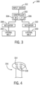
- FIG. 3 is a diagram of an embodiment of a control system 300 (e.g., electronic control system) configured to control the laterals belts 202, 203 of the header 200 of FIG. 2 .
- the control system 300 includes a controller 302 having a memory 304 and a processor 306.
- the memory 304 may be any type of non-transitory machine readable medium for storing data and executable instructions, such as random-access memory, read-only memory, rewritable flash memory, hard drives, optical discs, and the like.
- the processor 306 may execute instructions stored on the memory 304.
- the memory 304 may contain machine readable code, such as instructions, that may be executed by the processor 306.
- the controller 302 is configured to control a direction and a speed of the laterals belts 202, 203 via control signals sent to actuators 308, 310 coupled to the laterals belts 202, 203, respectively.
- the controller 302 may operate the laterals belts 202, 203 under an automatic belt speed mode.
- the speed of the lateral belts 202, 203 is linked to the ground speed of the agricultural vehicle.
- the controller 302 will keep the lateral belts moving at a set minimum threshold speed. The set minimum threshold speed keeps the lateral belts 202, 203 from stopping with the agricultural vehicle, while still tracking to the optimal speed during harvest operations.
- the controller 302 in response to a received input, automatically links the speed and the direction of the laterals belts 202, 203 (but not the infeed belt) of the header 200 to a vehicle speed and a vehicle direction of an agricultural vehicle having the header 200.
- the speed and the direction of the lateral belts 201, 202 will alter in response to changes in the vehicle speed and the vehicle direction when automatically linked. For example, in order to "de-slug" a slug of crop from the center section, an input may be received that causes the automatic linkage.
- the lateral belts 202, 203 reverse direction (e.g., away from the center section); if the agricultural vehicle stops, the lateral belts 202, 203 stop; if the agricultural vehicle changes speed, the lateral belts 202, 203 change speed.
- the received input may cease and the operator can return the agricultural vehicle to normal operation (where both the speed and the direction of the laterals belts 202, 203 will not be automatically linked to both the vehicle speed and the vehicle direction).
- an operator may provide an input (e.g., via an input device 312 coupled to the controller 302) that causes the automatic linkage of the speed and the direction of the laterals belts 202, 203 (but not the infeed belt) of the header 200 to the vehicle speed and the vehicle direction of an agricultural vehicle having the header 200.
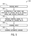
- the input device 312 may be a button 314 (e.g., shift button) located on a multi-function handle 316 (having multiple buttons 318 for other functions) located in a cabin (e.g., on the right-hand side of the operator) of the agricultural vehicle.
- the button 314 does not perform any function unless pressed in combination with another function button (e.g., one of the buttons 318).
- another function button e.g., one of the buttons 318.
- the operator wants to dislodge crop from the central section, the operator presses and holds the button to provide the input signal to the controller 302 that causes the automatic linkage of the speed and the direction of the laterals belts 202, 203 to the vehicle speed and the vehicle direction of an agricultural vehicle.
- the button 314 is being pressed, the input signal will be provided to the controller 302.
- the presence of the button 314 on the multi-function handle 316 enables the operator to activate the automatic linkage function while simultaneously slowing the agricultural vehicle to a stop to enable the reversal of the lateral belts 202, 203.
- the operator may control certain functions (controlling the vehicle speed and direction) of the agricultural vehicle while enabling the automatic linkage function. Once the crop is dislodged, the operator ceases pressing the button 314 and, thus, ceases providing the input signal to the controller 302, which causes the automatic linkage to cease.
- the button 314 may be located on a different handle or multi-function handle (e.g., located on the lefthand side of the operator). In certain embodiments, the button 314 may not be associated with any handle but located somewhere else within the cabin. In certain embodiments, the button 314 may only need to be pressed (and not held) to activate the automatic linkage function and then pressed again to deactivate the automatic linkage function.
- the input device may be a switch (e.g., toggle switch), an icon on a touch screen, or some other input device.
- the actuators 308, 310 for the lateral belts 202, 203 may be any suitable drive mechanism.
- the drive mechanism may be an electric motor.
- the drive mechanism may be a hydraulic motor.
- the lateral belts 202, 203 may be hydraulically controlled.
- a proportional flow control valve may be utilized in series with a directional control valve. To change belt direction, the following may occur: 1) reduce belt speed to zero utilizing the flow control valve, 2) change direction using the directional control valve, and 3) increase belt speed in the opposite direction (e.g., direction 226 in FIG. 2 ). The process may be performed in reverse to return to a forward speed (i.e., moving the belt in direction 205 in FIG. 2 ).
- FIG. 5 is a flow chart of an embodiment of a method 320 for operating the lateral belts 202, 203 that may be employed with the header 200 of FIG. 2 . It should be noted that although the method 320 is described below in a particular order, it should be understood that the method 320 may be performed in any suitable order. The method 320 may be performed by the controller 302 in FIG. 3 or another suitable computing device.
- the method 320 includes receiving an input from an input device (e.g., button 314 on the multi-function handle 316 in FIG. 3 ) (block 322).
- the method 320 also includes (simultaneous with and in response to receiving the input) automatically linking a speed and a direction of the lateral belts (e.g., lateral belts 202, 203 in FIGS. 2 and 3 ) to a vehicle speed and a vehicle direction of an agricultural vehicle having a header with the lateral belts (block 324).
- the automatic linkage continues until the receiving of the input ceases (e.g., until the button 314 on the multi-function handle 316 in FIG. 3 is no longer pressed and held).
- the method 320 further includes providing a control signal, when receiving the input, to the actuators (e.g., actuators 308, 310 in FIG. 3 ) of the lateral belts to alter the speed and direction of the lateral belts in response to changes in the vehicle speed and the vehicle direction (block 326).
- the actuators e.g., actuators 308, 310 in FIG. 3
- Blocks 322-326 of the method 320 may be utilized to dislodge crop form a center portion of the header (e.g., at the inlet feed belt or between the inlet feed belt and the lateral belts).
- the method 320 include, once the crop is dislodged, ceasing the input from the input device (e.g., ceasing the pressing and holding of the button 314 in FIG. 4 ) (block 328).
- the method 320 further includes (simultaneous with and in response to no longer receiving the input) ceasing the automatic linkage between the speed and the direction of the lateral belts to the vehicle speed and the vehicle direction of the agricultural vehicle (block 330).
- the operator can return the agricultural vehicle to normal operation (where both the speed and the direction of the laterals belts will not be automatically linked to both the vehicle speed and the vehicle direction).
- the speed of the lateral belts may be linked to a ground speed of the agricultural vehicle but, even if the vehicle is slowed to a stop, the lateral belts maintain a minimum set threshold speed that keeps the laterals belts moving. This keeps the lateral belts from stopping with the agricultural vehicle, while still tracking to the optimal speed during harvesting operations.
- a rotational direction e.g., affecting the direction of travel of the crop material
- speed of one or more augers lateral conveyors
Landscapes
- Life Sciences & Earth Sciences (AREA)
- Environmental Sciences (AREA)
- Harvester Elements (AREA)
- Harvesting Machines For Root Crops (AREA)
- Attitude Control For Articles On Conveyors (AREA)
- Engineering & Computer Science (AREA)
- Mechanical Engineering (AREA)
- Soil Sciences (AREA)
Claims (15)
- Landwirtschaftliches System (100) umfassend:ein landwirtschaftliches Fahrzeug;einen Erntevorsatz (200), der mit dem landwirtschaftlichen Fahrzeug verbunden ist und umfasst:einen Rahmen (201);ein erstes seitliches Förderband (202), das mit dem Rahmen (201) verbunden ist;ein zweites seitliches Förderband (203), das mit dem Rahmen (201) verbunden ist, wobei das erste und das zweite seitliche Förderband (202, 203) dazu eingerichtet sind, Erntegut in einer ersten Richtung seitlich zu einer zentralen Erntegut aufnehmenden Öffnung zu transportieren; undAktuatoren (308, 310), die dazu eingerichtet sind, eine Geschwindigkeit und eine Richtung des ersten und zweiten seitlichen Förderbands (202, 203) anzupassen; undeine Steuervorrichtung (302), wobei das landwirtschaftliche System (100) dadurch gekennzeichnet ist, dass die Steuervorrichtung (302) dazu eingerichtet ist:ein Eingangssignal von einem Eingabegerät (312) zu empfangen, das die Steuervorrichtung (302) dazu veranlasst, die Geschwindigkeit und die Richtung des ersten und zweiten seitlichen Förderbands (202, 203) automatisch mit der Fahrzeuggeschwindigkeit und der Fahrtrichtung des landwirtschaftlichen Fahrzeugs zu verknüpfen; undbei Empfang des Eingangssignals ein Steuersignal an die Aktuatoren (308, 310) bereitzustellen, das die Geschwindigkeit und die Richtung des ersten und zweiten seitlichen Förderbands (202, 203) in Reaktion auf Änderungen der Fahrzeuggeschwindigkeit und der Fahrtrichtung verändert.
- Landwirtschaftliches System (100) nach Anspruch 1, wobei das Steuersignal, wenn das Eingangssignal empfangen wird, das erste und zweite seitliche Förderband (202, 203) dazu veranlasst, anzuhalten, wenn das landwirtschaftliche Fahrzeug anhält.
- Landwirtschaftliches System (100) nach Anspruch 1, wobei das Steuersignal, wenn das Eingangssignal empfangen wird, das erste und zweite seitliche Förderband (202, 203) dazu veranlasst, sich in eine zweite Richtung entgegengesetzt zur ersten Richtung zu bewegen, wenn das landwirtschaftliche Fahrzeug sich rückwärts bewegt.
- Landwirtschaftliches System (100) nach Anspruch 3, wobei das Steuersignal, wenn das Eingangssignal empfangen wird, die Geschwindigkeit des ersten und zweiten seitlichen Förderbands (202, 203) ändert, wenn sich die Fahrzeuggeschwindigkeit des landwirtschaftlichen Fahrzeugs in der Rückwärtsrichtung ändert.
- Landwirtschaftliches System (100) nach Anspruch 1, wobei, wenn die Steuervorrichtung (302) das Eingangssignal nicht empfängt oder die Steuervorrichtung (302) aufhört, das Eingangssignal zu empfangen, die Richtung des ersten und zweiten seitlichen Förderbands (202, 203) nicht mit Änderungen der Fahrtrichtung des Fahrzeugs verknüpft ist.
- Landwirtschaftliches System (100) nach Anspruch 1, wobei, wenn die Steuervorrichtung (302) das Eingangssignal nicht empfängt oder die Steuervorrichtung (302) aufhört, das Eingangssignal zu empfangen, die Geschwindigkeit des ersten und zweiten seitlichen Förderbands (202, 203) mit Änderungen der Fahrzeuggeschwindigkeit verknüpft ist, bis die Geschwindigkeit des ersten und zweiten seitlichen Förderbands (202, 203) eine minimale Grenzwert-Geschwindigkeit erreicht.
- Landwirtschaftliches System (100) nach Anspruch 6, wobei, wenn die Steuervorrichtung (302) das Eingangssignal nicht empfängt oder die Steuervorrichtung (302) aufhört, das Eingangssignal zu empfangen, die Geschwindigkeit des ersten und zweiten seitlichen Förderbands (202, 203) bei der minimalen Grenzwert-Geschwindigkeit gehalten wird, wenn das landwirtschaftliche Fahrzeug angehalten wird.
- Landwirtschaftliches System (100) nach Anspruch 6, wobei, wenn das Eingangssignal empfangen wird, die Geschwindigkeit des ersten und zweiten seitlichen Förderbands (202, 203) nicht minimalen Grenzwert-Geschwindigkeit unterliegt.
- Landwirtschaftliches System (100) nach Anspruch 1, wobei das Eingabegerät (312) innerhalb eines Führerhauses (101) des landwirtschaftlichen Fahrzeugs angeordnet ist.
- Landwirtschaftliches System (100) nach Anspruch 9, wobei das Eingabegerät (312) einen Knopf (314) an einem Multifunktionsgriff (316) umfasst, der die Fahrzeuggeschwindigkeit und die Fahrtrichtung des Fahrzeugs steuert.
- Landwirtschaftliches System (100) nach Anspruch 10, wobei, solange der Knopf (314) gedrückt ist, die Geschwindigkeit und die Richtung des ersten und zweiten seitlichen Förderbands (202, 203) automatisch mit der Fahrzeuggeschwindigkeit und der Fahrtrichtung des landwirtschaftlichen Fahrzeugs verknüpft bleiben.
- Verfahren zum Betreiben von seitlichen Förderbändern (202, 203) an einem Erntevorsatz (200) eines landwirtschaftlichen Fahrzeugs (100), wobei das Verfahren dadurch gekennzeichnet ist, dass es umfasst:Empfangen eines Eingangssignals von einem Eingabegerät (312), das eine Steuervorrichtung (302) dazu veranlasst, eine Geschwindigkeit und eine Richtung sowohl des ersten seitlichen Förderbands (202) als auch des zweiten seitlichen Förderbands (203) automatisch mit der Fahrzeuggeschwindigkeit und der Fahrtrichtung des landwirtschaftlichen Fahrzeugs (100) zu verknüpfen, wobei das erste und das zweite seitliche Förderband (202, 203) mit einem Rahmen (201) des Erntevorsatzes (200) verbunden sind und dazu eingerichtet sind, Erntegut in einer ersten Richtung seitlich zu einer zentralen Erntegut aufnehmenden Öffnung zu transportieren; undwenn das Eingangssignal empfangen wird, Bereitstellen eines Steuersignals an Aktuatoren (308, 310), die mit dem ersten und zweiten seitlichen Förderband (202, 203) verbunden sind, das die Geschwindigkeit und die Richtung des ersten und zweiten seitlichen Förderbands (202, 203) in Reaktion auf Änderungen der Fahrzeuggeschwindigkeit und der Fahrtrichtung verändert.
- Verfahren nach Anspruch 12, wobei das Bereitstellen des Steuersignals, wenn das Eingangssignal empfangen wird, dazu führt, dass das erste und zweite seitliche Förderband (202, 203) anhalten, wenn das landwirtschaftliche Fahrzeug (100) anhält.
- Verfahren nach Anspruch 12, wobei das Bereitstellen des Steuersignals, wenn das Eingangssignal empfangen wird, die Richtung des ersten und zweiten seitlichen Förderbands (202, 203) zu einer zweiten Richtung ändert, die der ersten Richtung entgegengesetzt ist, wenn das landwirtschaftliche Fahrzeug (100) sich rückwärts bewegt.
- Verfahren nach Anspruch 12, wobei das Beenden des Eingangssignals dazu führt, dass die Richtung des ersten und zweiten seitlichen Förderbands (202, 203) nicht mit Änderungen der Fahrtrichtung des Fahrzeugs verknüpft sind.
Applications Claiming Priority (2)
| Application Number | Priority Date | Filing Date | Title |
|---|---|---|---|
| US202163180844P | 2021-04-28 | 2021-04-28 | |
| PCT/US2022/026502 WO2022232244A1 (en) | 2021-04-28 | 2022-04-27 | Systems and methods for controlling speed and direction of a lateral conveyor of an agricultural header |
Publications (2)
| Publication Number | Publication Date |
|---|---|
| EP4329468A1 EP4329468A1 (de) | 2024-03-06 |
| EP4329468B1 true EP4329468B1 (de) | 2025-06-04 |
Family
ID=81748812
Family Applications (1)
| Application Number | Title | Priority Date | Filing Date |
|---|---|---|---|
| EP22724300.3A Active EP4329468B1 (de) | 2021-04-28 | 2022-04-27 | Vorrichtung und verfahren zur kontrolle der geschwindigkeit und richtung eines lateralen förderers eines landwirtschaftlichen erntevorsatzes |
Country Status (6)
| Country | Link |
|---|---|
| US (1) | US20240196774A1 (de) |
| EP (1) | EP4329468B1 (de) |
| AR (1) | AR125724A1 (de) |
| AU (1) | AU2022266603A1 (de) |
| CA (1) | CA3216312A1 (de) |
| WO (1) | WO2022232244A1 (de) |
Families Citing this family (4)
| Publication number | Priority date | Publication date | Assignee | Title |
|---|---|---|---|---|
| US12364181B2 (en) | 2020-11-02 | 2025-07-22 | Deere & Company | Agricultural characteristic confidence and control |
| US12022772B2 (en) | 2021-01-22 | 2024-07-02 | Deere & Company | Agricultural header control |
| US12302788B2 (en) | 2022-04-08 | 2025-05-20 | Deere &Company | Residue characteristic confidence and control |
| US12507628B2 (en) | 2022-10-13 | 2025-12-30 | Deere & Company | Agricultural system with deck plate positioning control |
Family Cites Families (13)
| Publication number | Priority date | Publication date | Assignee | Title |
|---|---|---|---|---|
| US4430847A (en) * | 1982-07-23 | 1984-02-14 | Allis-Chalmers Corporation | Combine feed reverser |
| CA2527797C (en) * | 2005-11-18 | 2010-06-22 | Macdon Industries Ltd. | Crop cutting header with speed control of driven element using valve profiling |
| US7497069B2 (en) * | 2006-11-03 | 2009-03-03 | Macdon Industries Ltd. | Crop harvesting header with reversible drive to the sickle knife |
| US8186136B2 (en) * | 2009-04-03 | 2012-05-29 | Deere & Company | Agricultural harvester with a draper platform direction shuttle |
| RU2593890C2 (ru) * | 2011-05-31 | 2016-08-10 | СиЭнЭйч ИНДАСТРИАЛ АМЕРИКА ЭлЭлСи | Система и способ работы полотенной жатки во время и после операции очистки пробки |
| US10216156B2 (en) * | 2014-03-25 | 2019-02-26 | Macdon Industries Ltd. | Controlling cutting height and angle of a combine header |
| EP3114919B1 (de) * | 2015-07-08 | 2020-10-28 | Zürn Harvesting GmbH & Co. KG | Schneidwerksanordnung |
| DE102016115589A1 (de) * | 2016-08-23 | 2018-03-01 | Claas Selbstfahrende Erntemaschinen Gmbh | Bandschneidwerk |
| US11089727B2 (en) * | 2018-02-23 | 2021-08-17 | Macdon Industries | Harvesting machine with programmable inputs for header height and auxiliary function control |
| US10813288B2 (en) * | 2018-05-31 | 2020-10-27 | Deere & Company | Automated belt speed control |
| DE102018218442A1 (de) * | 2018-10-29 | 2020-04-30 | Deere & Company | Anordnung zur Steuerung des Betriebs eines Bandschneidwerks |
| US11497165B2 (en) * | 2019-10-24 | 2022-11-15 | Cnh Industrial America Llc | Controlled lateral belt reverse for draper head of agricultural combine |
| GB201918836D0 (en) * | 2019-12-19 | 2020-02-05 | Agco Ltd | Multi-section harvesting header and control method |
-
2022
- 2022-04-21 AR ARP220101038A patent/AR125724A1/es unknown
- 2022-04-27 CA CA3216312A patent/CA3216312A1/en active Pending
- 2022-04-27 WO PCT/US2022/026502 patent/WO2022232244A1/en not_active Ceased
- 2022-04-27 AU AU2022266603A patent/AU2022266603A1/en active Pending
- 2022-04-27 US US18/288,614 patent/US20240196774A1/en active Pending
- 2022-04-27 EP EP22724300.3A patent/EP4329468B1/de active Active
Also Published As
| Publication number | Publication date |
|---|---|
| CA3216312A1 (en) | 2022-11-03 |
| EP4329468A1 (de) | 2024-03-06 |
| WO2022232244A1 (en) | 2022-11-03 |
| US20240196774A1 (en) | 2024-06-20 |
| AR125724A1 (es) | 2023-08-09 |
| AU2022266603A1 (en) | 2023-11-09 |
Similar Documents
| Publication | Publication Date | Title |
|---|---|---|
| EP4329468B1 (de) | Vorrichtung und verfahren zur kontrolle der geschwindigkeit und richtung eines lateralen förderers eines landwirtschaftlichen erntevorsatzes | |
| AU2020414684B2 (en) | Control of a header of a harvester during a non-harvesting mode | |
| EP4081013B1 (de) | Systeme und verfahren zur begrenzung der rolleneinstellung bei einem landwirtschaftlichen erntevorsatz | |
| EP4081017B1 (de) | Erntevorsatzsteuerungssystem für erntemaschine | |
| US11997947B2 (en) | System and method for setting a profile of a header during a non-harvesting mode | |
| US9320198B2 (en) | System and method for controlling a draper header during and after a deslugging or clean out operation | |
| US12507630B2 (en) | Reel adjustment for an agricultural header | |
| US11234368B2 (en) | Cutter bar assembly for a harvester | |
| JP5102636B2 (ja) | コンバイン | |
| WO2022196116A1 (ja) | 自動運転方法、コンバイン及び自動運転システム | |
| CA3160406C (en) | Systems and methods for limiting reel adjustment in an agricultural header | |
| EP4360435B1 (de) | Systeme und verfahren zur anpassung des betriebs eines landwirtschaftlichen systems | |
| US20250000025A1 (en) | Rotary actuator system for work vehicle | |
| JP5166885B2 (ja) | コンバイン | |
| WO2023081427A1 (en) | Systems and methods for setting boundaries for a reel of an agricultural header | |
| JP2006109807A (ja) | コンバインの刈取装置 |
Legal Events
| Date | Code | Title | Description |
|---|---|---|---|
| STAA | Information on the status of an ep patent application or granted ep patent |
Free format text: STATUS: UNKNOWN |
|
| STAA | Information on the status of an ep patent application or granted ep patent |
Free format text: STATUS: THE INTERNATIONAL PUBLICATION HAS BEEN MADE |
|
| PUAI | Public reference made under article 153(3) epc to a published international application that has entered the european phase |
Free format text: ORIGINAL CODE: 0009012 |
|
| STAA | Information on the status of an ep patent application or granted ep patent |
Free format text: STATUS: REQUEST FOR EXAMINATION WAS MADE |
|
| 17P | Request for examination filed |
Effective date: 20231128 |
|
| AK | Designated contracting states |
Kind code of ref document: A1 Designated state(s): AL AT BE BG CH CY CZ DE DK EE ES FI FR GB GR HR HU IE IS IT LI LT LU LV MC MK MT NL NO PL PT RO RS SE SI SK SM TR |
|
| DAV | Request for validation of the european patent (deleted) | ||
| DAX | Request for extension of the european patent (deleted) | ||
| GRAP | Despatch of communication of intention to grant a patent |
Free format text: ORIGINAL CODE: EPIDOSNIGR1 |
|
| STAA | Information on the status of an ep patent application or granted ep patent |
Free format text: STATUS: GRANT OF PATENT IS INTENDED |
|
| GRAJ | Information related to disapproval of communication of intention to grant by the applicant or resumption of examination proceedings by the epo deleted |
Free format text: ORIGINAL CODE: EPIDOSDIGR1 |
|
| STAA | Information on the status of an ep patent application or granted ep patent |
Free format text: STATUS: REQUEST FOR EXAMINATION WAS MADE |
|
| INTG | Intention to grant announced |
Effective date: 20241023 |
|
| GRAP | Despatch of communication of intention to grant a patent |
Free format text: ORIGINAL CODE: EPIDOSNIGR1 |
|
| STAA | Information on the status of an ep patent application or granted ep patent |
Free format text: STATUS: GRANT OF PATENT IS INTENDED |
|
| INTC | Intention to grant announced (deleted) | ||
| INTG | Intention to grant announced |
Effective date: 20241218 |
|
| GRAS | Grant fee paid |
Free format text: ORIGINAL CODE: EPIDOSNIGR3 |
|
| GRAA | (expected) grant |
Free format text: ORIGINAL CODE: 0009210 |
|
| STAA | Information on the status of an ep patent application or granted ep patent |
Free format text: STATUS: THE PATENT HAS BEEN GRANTED |
|
| AK | Designated contracting states |
Kind code of ref document: B1 Designated state(s): AL AT BE BG CH CY CZ DE DK EE ES FI FR GB GR HR HU IE IS IT LI LT LU LV MC MK MT NL NO PL PT RO RS SE SI SK SM TR |
|
| REG | Reference to a national code |
Ref country code: GB Ref legal event code: FG4D |
|
| REG | Reference to a national code |
Ref country code: CH Ref legal event code: EP |
|
| REG | Reference to a national code |
Ref country code: DE Ref legal event code: R096 Ref document number: 602022015534 Country of ref document: DE |
|
| REG | Reference to a national code |
Ref country code: IE Ref legal event code: FG4D |
|
| REG | Reference to a national code |
Ref country code: NL Ref legal event code: MP Effective date: 20250604 |
|
| PG25 | Lapsed in a contracting state [announced via postgrant information from national office to epo] |
Ref country code: ES Free format text: LAPSE BECAUSE OF FAILURE TO SUBMIT A TRANSLATION OF THE DESCRIPTION OR TO PAY THE FEE WITHIN THE PRESCRIBED TIME-LIMIT Effective date: 20250604 Ref country code: FI Free format text: LAPSE BECAUSE OF FAILURE TO SUBMIT A TRANSLATION OF THE DESCRIPTION OR TO PAY THE FEE WITHIN THE PRESCRIBED TIME-LIMIT Effective date: 20250604 |
|
| REG | Reference to a national code |
Ref country code: LT Ref legal event code: MG9D |
|
| PG25 | Lapsed in a contracting state [announced via postgrant information from national office to epo] |
Ref country code: GR Free format text: LAPSE BECAUSE OF FAILURE TO SUBMIT A TRANSLATION OF THE DESCRIPTION OR TO PAY THE FEE WITHIN THE PRESCRIBED TIME-LIMIT Effective date: 20250905 Ref country code: NO Free format text: LAPSE BECAUSE OF FAILURE TO SUBMIT A TRANSLATION OF THE DESCRIPTION OR TO PAY THE FEE WITHIN THE PRESCRIBED TIME-LIMIT Effective date: 20250904 |
|
| PG25 | Lapsed in a contracting state [announced via postgrant information from national office to epo] |
Ref country code: PL Free format text: LAPSE BECAUSE OF FAILURE TO SUBMIT A TRANSLATION OF THE DESCRIPTION OR TO PAY THE FEE WITHIN THE PRESCRIBED TIME-LIMIT Effective date: 20250604 |
|
| PG25 | Lapsed in a contracting state [announced via postgrant information from national office to epo] |
Ref country code: BG Free format text: LAPSE BECAUSE OF FAILURE TO SUBMIT A TRANSLATION OF THE DESCRIPTION OR TO PAY THE FEE WITHIN THE PRESCRIBED TIME-LIMIT Effective date: 20250604 |
|
| PG25 | Lapsed in a contracting state [announced via postgrant information from national office to epo] |
Ref country code: HR Free format text: LAPSE BECAUSE OF FAILURE TO SUBMIT A TRANSLATION OF THE DESCRIPTION OR TO PAY THE FEE WITHIN THE PRESCRIBED TIME-LIMIT Effective date: 20250604 |
|
| PG25 | Lapsed in a contracting state [announced via postgrant information from national office to epo] |
Ref country code: RS Free format text: LAPSE BECAUSE OF FAILURE TO SUBMIT A TRANSLATION OF THE DESCRIPTION OR TO PAY THE FEE WITHIN THE PRESCRIBED TIME-LIMIT Effective date: 20250904 |
|
| PG25 | Lapsed in a contracting state [announced via postgrant information from national office to epo] |
Ref country code: LV Free format text: LAPSE BECAUSE OF FAILURE TO SUBMIT A TRANSLATION OF THE DESCRIPTION OR TO PAY THE FEE WITHIN THE PRESCRIBED TIME-LIMIT Effective date: 20250604 |
|
| PG25 | Lapsed in a contracting state [announced via postgrant information from national office to epo] |
Ref country code: NL Free format text: LAPSE BECAUSE OF FAILURE TO SUBMIT A TRANSLATION OF THE DESCRIPTION OR TO PAY THE FEE WITHIN THE PRESCRIBED TIME-LIMIT Effective date: 20250604 |
|
| PG25 | Lapsed in a contracting state [announced via postgrant information from national office to epo] |
Ref country code: PT Free format text: LAPSE BECAUSE OF FAILURE TO SUBMIT A TRANSLATION OF THE DESCRIPTION OR TO PAY THE FEE WITHIN THE PRESCRIBED TIME-LIMIT Effective date: 20251006 |
|
| REG | Reference to a national code |
Ref country code: AT Ref legal event code: MK05 Ref document number: 1799425 Country of ref document: AT Kind code of ref document: T Effective date: 20250604 |
|
| PG25 | Lapsed in a contracting state [announced via postgrant information from national office to epo] |
Ref country code: IS Free format text: LAPSE BECAUSE OF FAILURE TO SUBMIT A TRANSLATION OF THE DESCRIPTION OR TO PAY THE FEE WITHIN THE PRESCRIBED TIME-LIMIT Effective date: 20251004 |
|
| PG25 | Lapsed in a contracting state [announced via postgrant information from national office to epo] |
Ref country code: AT Free format text: LAPSE BECAUSE OF FAILURE TO SUBMIT A TRANSLATION OF THE DESCRIPTION OR TO PAY THE FEE WITHIN THE PRESCRIBED TIME-LIMIT Effective date: 20250604 Ref country code: SM Free format text: LAPSE BECAUSE OF FAILURE TO SUBMIT A TRANSLATION OF THE DESCRIPTION OR TO PAY THE FEE WITHIN THE PRESCRIBED TIME-LIMIT Effective date: 20250604 |
|
| PG25 | Lapsed in a contracting state [announced via postgrant information from national office to epo] |
Ref country code: CZ Free format text: LAPSE BECAUSE OF FAILURE TO SUBMIT A TRANSLATION OF THE DESCRIPTION OR TO PAY THE FEE WITHIN THE PRESCRIBED TIME-LIMIT Effective date: 20250604 |
|
| PG25 | Lapsed in a contracting state [announced via postgrant information from national office to epo] |
Ref country code: EE Free format text: LAPSE BECAUSE OF FAILURE TO SUBMIT A TRANSLATION OF THE DESCRIPTION OR TO PAY THE FEE WITHIN THE PRESCRIBED TIME-LIMIT Effective date: 20250604 |
|
| PG25 | Lapsed in a contracting state [announced via postgrant information from national office to epo] |
Ref country code: SK Free format text: LAPSE BECAUSE OF FAILURE TO SUBMIT A TRANSLATION OF THE DESCRIPTION OR TO PAY THE FEE WITHIN THE PRESCRIBED TIME-LIMIT Effective date: 20250604 |