EP4329127A2 - Schwarzstartsteuerungsverfahren auf der basis einer vielzahl von wandlersubarrays und vorrichtung - Google Patents
Schwarzstartsteuerungsverfahren auf der basis einer vielzahl von wandlersubarrays und vorrichtung Download PDFInfo
- Publication number
- EP4329127A2 EP4329127A2 EP23193572.7A EP23193572A EP4329127A2 EP 4329127 A2 EP4329127 A2 EP 4329127A2 EP 23193572 A EP23193572 A EP 23193572A EP 4329127 A2 EP4329127 A2 EP 4329127A2
- Authority
- EP
- European Patent Office
- Prior art keywords
- converter
- target
- voltage
- subarray
- alternating voltage
- Prior art date
- Legal status (The legal status is an assumption and is not a legal conclusion. Google has not performed a legal analysis and makes no representation as to the accuracy of the status listed.)
- Granted
Links
Images


Classifications
-
- H—ELECTRICITY
- H02—GENERATION; CONVERSION OR DISTRIBUTION OF ELECTRIC POWER
- H02J—ELECTRIC POWER NETWORKS; CIRCUIT ARRANGEMENTS OR SYSTEMS FOR SUPPLYING OR DISTRIBUTING ELECTRIC POWER; SYSTEMS FOR STORING ELECTRIC ENERGY
- H02J3/00—Circuit arrangements for AC mains or AC distribution networks
- H02J3/001—Arrangements for handling faults or abnormalities, e.g. emergencies or contingencies
-
- H—ELECTRICITY
- H02—GENERATION; CONVERSION OR DISTRIBUTION OF ELECTRIC POWER
- H02J—ELECTRIC POWER NETWORKS; CIRCUIT ARRANGEMENTS OR SYSTEMS FOR SUPPLYING OR DISTRIBUTING ELECTRIC POWER; SYSTEMS FOR STORING ELECTRIC ENERGY
- H02J3/00—Circuit arrangements for AC mains or AC distribution networks
- H02J3/38—Arrangements for feeding a single network from two or more generators or sources in parallel; Arrangements for feeding already energised networks from additional generators or sources in parallel
- H02J3/46—Controlling the sharing of generated power between the generators, sources or networks
-
- H—ELECTRICITY
- H02—GENERATION; CONVERSION OR DISTRIBUTION OF ELECTRIC POWER
- H02J—ELECTRIC POWER NETWORKS; CIRCUIT ARRANGEMENTS OR SYSTEMS FOR SUPPLYING OR DISTRIBUTING ELECTRIC POWER; SYSTEMS FOR STORING ELECTRIC ENERGY
- H02J3/00—Circuit arrangements for AC mains or AC distribution networks
- H02J3/28—Arrangements for balancing of the load in networks by storage of energy
-
- H—ELECTRICITY
- H02—GENERATION; CONVERSION OR DISTRIBUTION OF ELECTRIC POWER
- H02J—ELECTRIC POWER NETWORKS; CIRCUIT ARRANGEMENTS OR SYSTEMS FOR SUPPLYING OR DISTRIBUTING ELECTRIC POWER; SYSTEMS FOR STORING ELECTRIC ENERGY
- H02J3/00—Circuit arrangements for AC mains or AC distribution networks
- H02J3/38—Arrangements for feeding a single network from two or more generators or sources in parallel; Arrangements for feeding already energised networks from additional generators or sources in parallel
- H02J3/381—Dispersed generators
-
- H—ELECTRICITY
- H02—GENERATION; CONVERSION OR DISTRIBUTION OF ELECTRIC POWER
- H02J—ELECTRIC POWER NETWORKS; CIRCUIT ARRANGEMENTS OR SYSTEMS FOR SUPPLYING OR DISTRIBUTING ELECTRIC POWER; SYSTEMS FOR STORING ELECTRIC ENERGY
- H02J3/00—Circuit arrangements for AC mains or AC distribution networks
- H02J3/38—Arrangements for feeding a single network from two or more generators or sources in parallel; Arrangements for feeding already energised networks from additional generators or sources in parallel
- H02J3/40—Synchronisation of generators for connection to a network or to another generator
-
- H—ELECTRICITY
- H02—GENERATION; CONVERSION OR DISTRIBUTION OF ELECTRIC POWER
- H02J—ELECTRIC POWER NETWORKS; CIRCUIT ARRANGEMENTS OR SYSTEMS FOR SUPPLYING OR DISTRIBUTING ELECTRIC POWER; SYSTEMS FOR STORING ELECTRIC ENERGY
- H02J2101/00—Supply or distribution of decentralised, dispersed or local electric power generation
- H02J2101/20—Dispersed power generation using renewable energy sources
- H02J2101/22—Solar energy
- H02J2101/24—Photovoltaics
Definitions
- This application is applied to the field of power electronics technologies, and in particular, relates to a black start control method based on a plurality of converter subarrays and an apparatus.
- a black start of the power system is a process to start a unit with a self-starting capability when a large-scale power outage of the system occurs due to man-made factors, natural disasters, or device faults and no external power supply is available, to further drive a unit having no self-starting capability to start, and gradually expand a scope of system recovery, so that the entire system can be recovered and power can be supplied to users as soon as possible, and loss caused by power outages is minimized.
- an energy storage system in the system or a power electronic converter in a photovoltaic system can be used to establish a power grid voltage, to implement a black start of the power grid, and recover power supply of the power grid.
- This type of black start method does not require additional power grid facilities, but requires only an original converter and control system to implement a black start operation.
- a huge inrush current generated by switch-on may directly trigger a protection mechanism of a converter, resulting in a black start failure of the power grid. Therefore, a manner of first closing a circuit and then starting a power supply is generally used to prevent the inrush.
- Embodiments of this application provide a black start control method based on a plurality of converter subarrays and an apparatus, to improve reliability of a black start performed based on coordination of the plurality of converter subarrays.
- an embodiment of this application provides a black start controller based on a plurality of converter subarrays.
- At least one of the plurality of converter subarrays includes at least one converter, an input port of each of the plurality of converter subarrays is connected to a direct current source, and an output port of each of the plurality of converter subarrays is connected to a first alternating current bus through a first transformer and a control switch.
- the black start controller is configured to: sequentially perform working processes of a first voltage adjustment phase to an N th voltage adjustment phase after controlling the control switch to be turned on and controlling a converter in each converter subarray to be powered on; and in an n th voltage adjustment phase of the first voltage adjustment phase to the N th voltage adjustment phase, synchronously send an n th target voltage adjustment instruction to each converter subarray, to control each converter in the converter subarray to establish an n th target alternating voltage, so that the n th target alternating voltage is converted by the first transformer into an n th target bus alternating voltage input to the first alternating current bus, where n and N are integers greater than 1, 1 ⁇ n ⁇ N, the n th target alternating voltage is greater than an (n-1) th target alternating voltage, the n th target bus alternating voltage is greater than an (n-1) th target bus alternating voltage, and an N th target bus alternating voltage is a rated alternating voltage of the first alternating current bus.
- a second target alternating voltage is greater than a first target alternating voltage
- a third target alternating voltage is greater than the second target alternating voltage
- an N th target alternating voltage is greater than an (N-1) th target alternating voltage
- a second target bus alternating voltage is greater than a first target bus alternating voltage
- a third target bus alternating voltage is greater than the second target bus alternating voltage
- the N th target bus alternating voltage is greater than an (N-1) th target bus alternating voltage
- the N th target bus alternating voltage is the rated alternating voltage of the first alternating current bus.
- a process of establishing the rated voltage of the first alternating current bus is divided into a plurality of phases. In each phase, a voltage is increased by a specific amplitude, and this process repeats until the rated voltage is established, to help a power grid establish a voltage and recover operation of a power system.
- a problem of a circulating current between subarrays in a black start process of a plurality of converter subarrays in a power station or microgrid system can be resolved, reliability of a black start of the power grid can be improved, and an application scenario of the black start of a plurality of converter subarrays can be enhanced, especially a black start scenario of a transmission line with a large reactive power.
- the controller synchronously sends a first target voltage adjustment instruction to the converter subarray.
- Each converter in the converter subarray may establish a first target alternating voltage based on the first target voltage adjustment instruction.
- the first target alternating voltage is converted by a corresponding first transformer into a first target bus alternating voltage output to the first alternating current bus.
- the controller synchronously sends a second target voltage adjustment instruction to the converter subarray.
- Each converter in the converter subarray may establish a second target alternating voltage based on the second target voltage adjustment instruction.
- the second target alternating voltage is converted by a corresponding first transformer into a second target bus alternating voltage output to the first alternating current bus.
- the rest may be deduced by analogy, and details are not described herein again.
- the black start controller includes a first controller and a plurality of second controllers, the first controller is communicatively connected to the plurality of second controllers, a converter in each converter subarray has a drive controller, the plurality of second controllers and the plurality of converter subarrays are disposed in a one-to-one correspondence, and the second controller is communicatively connected to a drive controller in a converter in a corresponding converter subarray.
- the first controller is configured to synchronously send the n th target voltage adjustment instruction to each of the plurality of second controllers based on an n th piece of target alternating voltage data in a pre-established adjustment sequence in the n th voltage adjustment phase.
- Any one of the plurality of second controllers is configured to send an n th voltage output instruction to a communicatively connected drive controller based on the received n th target voltage adjustment instruction.
- the drive controller is configured to control, based on the received n th voltage output instruction, a corresponding converter to establish the n th target alternating voltage.
- the adjustment sequence has a first piece of target alternating voltage data to an N th piece of target alternating voltage data that are sequentially arranged.
- the second controller and a corresponding converter subarray may be disposed in a same area.
- the second controller is disposed in an operation area in which a corresponding converter subarray is located.
- an uninterrupted power supply (Uninterrupted Power Supply, UPS) is further disposed in the power system, and the UPS is connected to each second controller, and is configured to store electric energy transmitted on a power grid before the power grid or an electric device is powered off, and provide the stored electric energy to the second controller when the power grid or the electric device is powered off, to implement a black start.
- the power system further includes a power module bridged between the UPS and the second controller, and the UPS may supply power to the second controller by using the power module.
- the first controller may have a communication component for communicating with an external device or an external server.
- the communication component may include network communication protocol modules such as a Wi-Fi module and a wired Ethernet communication protocol module, so that the first controller can implement communication of a control signal and a data signal with the external device or the external server.
- the second controller may have a communication component for communicating with an external device or an external server.
- the communication component may include network communication protocol modules such as a Wi-Fi module and a wired Ethernet communication protocol module, so that the second controller can implement communication of a control signal and a data signal with the external device or the external server.
- the communication component of the first controller is communicatively connected to the communication component of the second controller, so that the first controller and the second controller implement communication of a control signal and a data signal.
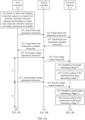
- a staff inputs a black start enabling instruction to the first controller.
- the first controller selects a converter subarray participating in a black start, and determines that the selected converter subarray is powered on or available. Then, the first controller sends an initial black start preparation instruction to the second controller, and the second controller sends a target black start preparation instruction to a drive controller in a converter in the converter subarray based on the received initial black start preparation instruction. If the drive controller in the converter in the converter subarray completes preparation, the drive controller sends an initial black start preparation completion instruction to the second controller.
- the second controller sends a target black start preparation completion instruction to the first controller based on the initial black start preparation completion instruction.
- the first controller may start to sequentially perform the working processes of the first voltage adjustment phase to the N th voltage adjustment phase.
- a staff may alternatively input a black start enabling instruction to the first controller by using an upper-level controller.
- the first controller selects a converter subarray participating in a black start, and determines that the selected converter subarray is powered on or available. Then, the first controller sends an initial black start preparation instruction to the second controller, and the second controller sends a target black start preparation instruction to a drive controller in a converter in the converter subarray based on the received initial black start preparation instruction. If the drive controller in the converter in the converter subarray completes preparation, the drive controller sends an initial black start preparation completion instruction to the second controller.
- the second controller sends a target black start preparation completion instruction to the first controller based on the initial black start preparation completion instruction.
- the first controller may start to sequentially perform the working processes of the first voltage adjustment phase to the N th voltage adjustment phase.
- the second controller may be further configured to monitor operating status information in the corresponding converter subarray, for example, a voltage, a current, a frequency, and a power (active power and reactive power) of a converter in the converter subarray.
- the first controller may obtain the information such as the voltage, the current, the frequency, and the power (active power and reactive power) of the converter subarray from the second controller.
- the first controller stores the pre-established adjustment sequence.
- the adjustment sequence has the first piece of target alternating voltage data to the N th piece of target alternating voltage data that are sequentially arranged.
- a manner of storing the first piece of target alternating voltage data to the N th piece of target alternating voltage data is not limited in this application.
- the first piece of target alternating voltage data to the N th piece of target alternating voltage data may be stored in the first controller in a binary, decimal, or hexadecimal manner.
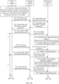
- the first controller is configured to synchronously send the first target voltage adjustment instruction to the second controllers based on the first piece of target alternating voltage data in the pre-established adjustment sequence in the first voltage adjustment phase.
- the second controllers may synchronously receive the first target voltage adjustment instruction.
- the second controller is configured to send a first voltage output instruction to a communicatively connected drive controller in the converter subarray based on the received first target voltage adjustment instruction.
- the drive controller in the converter subarray is configured to control, based on the received first voltage output instruction, a converter in the converter subarray to convert electric energy of a direct current source into the first target alternating voltage of a power frequency alternating current, to establish the first target alternating voltage V 1 .
- the rest may be deduced by analogy, and details are not described herein again.
- the adjustment sequence further includes one or more pieces of power equalization control data.
- the n th piece of target alternating voltage data corresponds to and adjacent to a q th piece of power equalization control data, and the n th piece of target alternating voltage data is set before the q th piece of power equalization control data.
- the adjustment sequence includes a plurality of pieces of power equalization control data. If the adjustment sequence includes Q pieces of power equalization control data, the adjustment sequence includes a first piece of power equalization control data to a Q th piece of power equalization control data.
- Q is an integer greater than 1
- q is a positive integer, and 1 ⁇ q ⁇ Q.
- the first controller is further configured to: determine a q th target power of each converter subarray based on the q th piece of power equalization control data in the adjustment sequence, and synchronously send, to the corresponding second controller in each converter subarray based on the q th target power of each converter subarray, a q th power adjustment instruction carrying the q th corresponding target power.
- the second controller is further configured to send a q th power output instruction to the communicatively connected drive controller based on the received q th power adjustment instruction.
- the drive controller is further configured to control, based on the received q th power output instruction, the corresponding converter to output the q th target power.
- the first controller is further configured to: determine a first target power of the converter subarray based on the first piece of power equalization control data in the adjustment sequence, and synchronously send, to the second controller based on the first target power of the converter subarray, a first power adjustment instruction carrying the first target power.
- the second controller is further configured to send the first power output instruction to the communicatively connected drive controller in the converter subarray based on the received first power adjustment instruction carrying the first target power.
- the drive controller in the converter subarray is further configured to: control, based on the received first power output instruction, the corresponding converter to output the first target power, and control power equalization between converter subarrays, so that a problem such as load power unequalization can be resolved. The rest may be deduced by analogy, and details are not described herein again.
- a quantity of pieces of the power equalization control data is the same as a quantity of pieces of the target alternating voltage data.
- the adjustment sequence includes the first piece of target alternating voltage data, the first piece of power equalization control data, the second piece of target alternating voltage data, the second piece of power equalization control data, the third piece of target alternating voltage data, the third piece of power equalization control data, ..., the N th piece of target alternating voltage data, and the Q th piece of power equalization control data.
- a quantity of pieces of the power equalization control data is less than a quantity of pieces of the target alternating voltage data.
- at least one piece of target alternating voltage data is set between two adjacent pieces of power equalization control data. In other words, Q ⁇ N.
- no power equalization control data may be set between some of the target alternating voltage data.
- the first controller is further configured to: obtain a power of the output port of each converter subarray, determine an average power value of each converter subarray based on the power of the output port of each converter subarray and a quantity of converters in each converter subarray, and determine the determined average power value of each converter subarray as a q th target power of each converter subarray.
- the first controller may obtain the power of the output port of each converter subarray from a monitor system.
- the first controller may obtain the power of the output port of the converter subarray from the first controller corresponding to each converter subarray.
- the drive controller is further configured to: after controlling a corresponding converter to establish an n th target alternating voltage, control the corresponding converter to correct a phase of the established n th target alternating voltage based on an alternating voltage of an output port of a converter subarray in which the converter is located.
- the drive controller in each converter of each converter subarray is further configured to: after controlling a corresponding converter to establish an n th target alternating voltage, control the corresponding converter to correct a phase of the established n th target alternating voltage based on an alternating voltage of an output port of a converter subarray in which the converter is located.
- the drive controller is further configured to: after controlling a corresponding converter to establish the first target alternating voltage, control the corresponding converter to correct a phase of the established first target alternating voltage based on an alternating voltage of an output port of a converter subarray in which the converter is located. The rest may be deduced by analogy, and details are not described herein again.
- the power system further includes a switch control module
- the first controller is further communicatively connected to the switch control module
- the switch control module is connected to the control switch.
- the first controller is further configured to send an identifier (for example, an ID) of each of the plurality of converter subarrays to the switch control module.
- the switch control module is configured to control a control switch connected to each of the plurality of converter subarrays to be turned on.
- the first controller is further configured to synchronously send a subarray start instruction to the second controller corresponding to each of the plurality of converter subarrays.
- the second controller is further configured to send a converter power-on instruction to the communicatively connected drive controller based on the received subarray start instruction.
- the drive controller is configured to control, based on the received converter power-on instruction, a corresponding converter to be powered on.
- the switch control module controls a control switch connected to each converter subarray to be turned on, so that the output port of each converter in each converter subarray and an input end of the first transformer are connected in a parallel manner.
- an output end of each first transformer and the first alternating current bus are connected in a parallel manner.
- the converters in the converter subarrays and an alternating current power grid that needs to be started and run can be connected to each other on a circuit.
- the first controller synchronously sends a subarray start instruction to the second controller corresponding to each of the plurality of converter subarrays.
- each second controller sends a converter power-on instruction to the communicatively connected drive controller based on the received subarray start instruction.
- the drive controller controls, based on the received converter power-on instruction, a corresponding converter to be powered on, so that each converter in the converter subarray is already powered on or available before a black start is implemented.
- the power system further includes a switch control module
- the first controller is further communicatively connected to the switch control module
- the switch control module is connected to the control switch.
- the first controller is further configured to send an identifier (for example, an ID) of each of the plurality of converter subarrays to the switch control module.
- the switch control module is configured to: control control switches connected to a first part of converter subarrays in the plurality of converter subarrays to be turned on, and control control switches connected to a second part of converter subarrays in the plurality of converter subarrays to be turned on.
- a quantity of converter subarrays in the first part of converter subarrays is less than a quantity of converter subarrays in the second part of converter subarrays.
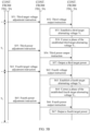
- the first controller is further configured to: after the control switches connected to the first part of converter subarrays are turned on, synchronously send a first part of subarray start instructions to second controllers corresponding to the first part of converter subarrays, and synchronously send initial voltage adjustment instructions to the second controllers corresponding to the first part of converter subarrays; and after the control switches connected to the second part of converter subarrays are turned on, synchronously send a second part of subarray start instructions to second controllers corresponding to the second part of converter subarrays.
- the second controllers corresponding to the first part of converter subarrays are further configured to: send, based on the received first part of subarray start instructions, converter power-on instructions to the communicatively connected drive controllers, and send initial voltage output instructions to the communicatively connected drive controllers based on the received initial voltage adjustment instructions.
- the second controllers corresponding to the second part of converter subarrays are further configured to send converter power-on instructions to the communicatively connected drive controllers based on the received second part of subarray start instructions.
- the drive controller in each converter subarray is configured to control, based on the received converter power-on instruction, a corresponding converter to be powered on.
- the drive controller communicatively connected to the second controller corresponding to the first part of converter subarrays is further configured to control, based on the received initial voltage output instruction, the corresponding converter to establish an initial alternating voltage, so that the initial alternating voltage is converted by the first transformer into an initial bus alternating voltage input to the first alternating current bus.
- the initial bus alternating voltage is less than the first target bus alternating voltage.
- the switch control module may control control switches connected to the first part of converter subarrays in the plurality of converter subarrays to be turned on, so that an output port of each converter in each of the first part of converter subarrays and an input end of a corresponding transformer are connected in a parallel manner, and output ends of transformers corresponding to the first part of converter subarrays and the first alternating current bus are connected.
- the first controller synchronously sends the first part of subarray start instructions to the second controllers corresponding to the first part of converter subarrays.
- the second controllers corresponding to the first part of converter subarrays send converter power-on instructions to the communicatively connected drive controllers based on the received first part of subarray start instructions.
- the drive controller controls, based on the received converter power-on instruction, a corresponding converter to be powered on, so that each converter in the first part of converter subarrays is already powered on or available before the black start is implemented.
- the first controller synchronously sends the initial voltage adjustment instruction to the corresponding second controller in each of the first part of converter subarrays.
- the corresponding second controller in each of the first part of converter subarrays sends the initial voltage output instruction to the communicatively connected drive controller based on the received initial voltage adjustment instruction.
- the drive controller controls, based on the received initial voltage output instruction, a corresponding converter to establish an initial alternating voltage, so that the initial alternating voltage is converted by the first transformer into the initial bus alternating voltage input to the first alternating current bus.
- the switch control module controls the control switches connected to the second part of converter subarrays in the plurality of converter subarrays to be turned on.
- the first controller synchronously sends the second part of subarray start instructions to the second controllers corresponding to the second part of converter subarrays.
- the second controllers corresponding to the second part of converter subarrays send converter power-on instructions to the communicatively connected drive controllers based on the received second part of subarray start instructions.
- the drive controller controls, based on the received converter power-on instruction, a corresponding converter to be powered on, so that each converter in the second part of converter subarrays is already powered on or available before the black start is implemented.
- a quantity of converter subarrays in the first part of converter subarrays is less than a quantity of converter subarrays in the second part of converter subarrays.
- the first part of converter subarrays include one of the plurality of converter subarrays
- the second part of converter subarrays include other converter subarrays of the plurality of converter subarrays other than the first part of converter subarrays.
- the UPS is further connected to the switch control module, and is configured to provide stored electric energy to the switch control module when the power grid or the electric device is powered off, to implement the black start.
- each converter in each converter subarray is a voltage source converter.
- the second controller is further configured to synchronously send the n th voltage output instruction to a drive controller in each converter in the corresponding converter subarray.
- the second controller is configured to synchronously send the first voltage output instruction to the drive controller in each converter in the corresponding converter subarray, so that the drive controller in each converter in the converter subarray controls a switching frequency of a switch in the corresponding converter based on the received first voltage output instruction, to convert electric energy of a direct current source into the first target alternating voltage of a power frequency alternating current, and establish the first target alternating voltage.
- the second controller controls establishment of other target alternating voltages may be deduced by analogy. Details are not described herein again.
- each converter in each converter subarray is a voltage source converter.
- one converter is a master converter
- other converters are slave converters.
- the second controller is further configured to send the n th voltage output instruction to a drive controller in a master converter in the corresponding converter subarray.
- the drive controller connected to the master converter is further configured to: control, based on the received n th voltage output instruction, the master converter to establish the n th target alternating voltage, and send a slave voltage output instruction to a drive controller in the slave converter based on the received n th voltage output instruction.
- the drive controller in the slave converter is configured to control, based on the received slave voltage output instruction, the slave converter to establish the n th target alternating voltage.
- one converter is a master converter, and other converters are slave converters.
- the second controller corresponding to the converter subarray is configured to send the n th voltage output instruction to a drive controller in the master converter in the converter subarray.
- the drive controller connected to the master converter in the converter subarray is further configured to: control, based on the received n th voltage output instruction, the master converter to establish the n th target alternating voltage, and send a slave voltage output instruction to a drive controller in the slave converter in the converter subarray based on the received n th voltage output instruction.
- the drive controller in the slave converter in the converter subarray is configured to control, based on the received slave voltage output instruction, the slave converter to establish the n th target alternating voltage.
- each converter subarray one converter is a voltage source converter, and other converters are current source converters.
- the second controller is further configured to send the n th voltage output instruction to a drive controller connected to the voltage source converter.
- one converter is a voltage source converter
- other converters are current source converters.
- the second controller corresponding to the converter subarray is further configured to send the n th voltage output instruction to a drive controller connected to the voltage source converter in the converter subarray.
- a voltage of an output port of a current source converter in the converter subarray may follow a voltage of an output port of the voltage source converter.
- the power system in this application is applicable to scenarios such as a photovoltaic power generation system, an energy storage power station, and a microgrid.
- the converter subarray may include a converter and a monitor.
- the converter may have a drive controller, and a switching frequency of a switch in the converter is controlled by using the drive controller, so that the converter converts electric energy in a direct current source into a power frequency (for example, 50 Hz) alternating current.
- a power frequency for example, 50 Hz
- the direct current source may be set to an energy storage apparatus.
- the converter is an energy storage converter
- the converter subarray is an energy storage converter subarray
- the energy storage converter may convert electric energy in the energy storage apparatus into a power frequency (for example, 50 Hz) alternating current.
- the direct current source may be set to a photovoltaic power generation apparatus.
- the converter is a photovoltaic converter
- the converter subarray is a photovoltaic converter subarray
- the photovoltaic converter may convert electric energy in the photovoltaic power generation apparatus into a power frequency (for example, 50 Hz) alternating current.
- a power frequency is generally a mains frequency. In China, the power frequency is 50 Hz. In other countries, the power frequency is 60 Hz. If a frequency of the power frequency alternating current is 50 Hz, a power frequency cycle is 0.02 seconds.
- the interval in the first voltage adjustment phase to the N th voltage adjustment phase, there is an interval between start moments of every two adjacent voltage adjustment phases, and the interval is greater than one power frequency cycle. For example, there is an interval between a start moment of the second voltage adjustment phase and a start moment of the first voltage adjustment phase, and the interval is greater than one power frequency cycle. There is an interval between a start moment of the third voltage adjustment phase and the start moment of the second voltage adjustment phase, and the interval is greater than one power frequency cycle.... There is an interval between a start moment of the N th voltage adjustment phase and a start moment of the (N-1) th voltage adjustment phase, and the interval is greater than one power frequency cycle.
- intervals between start moments of every two adjacent voltage adjustment phases are the same.
- the interval between the start moment of the second voltage adjustment phase and the start moment of the first voltage adjustment phase, the interval between the start moment of the third voltage adjustment phase and the start moment of the second voltage adjustment phase, ..., and the interval between the start moment of the N th voltage adjustment phase and the start moment of the (N-1) th voltage adjustment phase are the same.
- At least some voltage differences in voltage differences between target alternating voltages in every two adjacent voltage adjustment phases are the same.
- absolute values of at least some voltage differences in absolute values of voltage differences between target alternating voltages in every two adjacent voltage adjustment phases are the same.
- absolute values of at least some voltage differences in absolute values of voltage differences between target alternating voltages in every two adjacent voltage adjustment phases may be the same.
- an absolute value of a voltage difference between the first target alternating voltage and the second target alternating voltage is the same as an absolute value of a voltage difference between the second target alternating voltage and the third target alternating voltage.
- the absolute value of the voltage difference between the second target alternating voltage and the third target alternating voltage is the same as an absolute value of a voltage difference between the third target alternating voltage and the fourth target alternating voltage.
- the absolute value of the voltage difference between the third target alternating voltage and the fourth target alternating voltage is the same as an absolute value of a voltage difference between the fourth target alternating voltage and the fifth target alternating voltage.
- the absolute value of the voltage difference between the fourth target alternating voltage and the fifth target alternating voltage is the same as an absolute value of a voltage difference between the fifth target alternating voltage and the sixth target alternating voltage. The rest may be deduced by analogy, and details are not described herein again.
- voltage differences between target alternating voltages in every two adjacent voltage adjustment phases may alternatively be the same.
- the absolute value of the voltage difference between the first target alternating voltage and the second target alternating voltage, the absolute value of the voltage difference between the second target alternating voltage and the third target alternating voltage, and the absolute value of the voltage difference between the third target alternating voltage and the fourth target alternating voltage, the absolute value of the voltage difference between the fourth target alternating voltage and the fifth target alternating voltage, the absolute value of the voltage difference between the fifth target alternating voltage and the sixth target alternating voltage are the same. The rest may be deduced by analogy, and details are not described herein again.
- voltage differences between target alternating voltages in every two adjacent voltage adjustment phases sequentially increase.
- absolute values of voltage differences between target alternating voltages in every two adjacent voltage adjustment phases sequentially increase.
- an absolute value of a voltage difference between the first target alternating voltage and the second target alternating voltage is less than an absolute value of a voltage difference between the second target alternating voltage and the third target alternating voltage.
- the absolute value of the voltage difference between the second target alternating voltage and the third target alternating voltage is less than an absolute value of a voltage difference between the third target alternating voltage and the fourth target alternating voltage.
- the absolute value of the voltage difference between the third target alternating voltage and the fourth target alternating voltage is less than an absolute value of a voltage difference between the fourth target alternating voltage and the fifth target alternating voltage.
- An absolute value of a voltage difference between the fifth target alternating voltage and the sixth target alternating voltage is less than an absolute value of a voltage difference between the sixth target alternating voltage and the seventh target alternating voltage.
- voltage differences between target alternating voltages in every two adjacent voltage adjustment phases sequentially decrease.
- absolute values of voltage differences between target alternating voltages in every two adjacent voltage adjustment phases sequentially decrease.
- an absolute value of a voltage difference between the first target alternating voltage and the second target alternating voltage is greater than an absolute value of a voltage difference between the second target alternating voltage and the third target alternating voltage.
- the absolute value of the voltage difference between the second target alternating voltage and the third target alternating voltage is greater than an absolute value of a voltage difference between the third target alternating voltage and the fourth target alternating voltage.
- the absolute value of the voltage difference between the third target alternating voltage and the fourth target alternating voltage is greater than an absolute value of a voltage difference between the fourth target alternating voltage and the fifth target alternating voltage.
- An absolute value of a voltage difference between the fifth target alternating voltage and the sixth target alternating voltage is greater than an absolute value of a voltage difference between the sixth target alternating voltage and the seventh target alternating voltage.
- an embodiment of this application further provides a primary controller based on a plurality of converter subarrays.
- At least one of the plurality of converter subarrays includes at least one converter, an input port of each of the plurality of converter subarrays is connected to a direct current source, and an output port of each of the plurality of converter subarrays is connected to a first alternating current bus through a first transformer and a control switch.
- the primary controller is communicatively connected to a plurality of second controllers, the plurality of second controllers and the plurality of converter subarrays are disposed in a one-to-one correspondence, and the second controller is configured to control a corresponding converter subarray to work.
- the primary controller is configured to: sequentially perform working processes of a first voltage adjustment phase to an N th voltage adjustment phase after controlling the control switch to be turned on and controlling a converter in each converter subarray to be powered on; and in an n th voltage adjustment phase of the first voltage adjustment phase to the N th voltage adjustment phase, synchronously send an n th target voltage adjustment instruction to each second controller, so that each second controller controls a corresponding converter subarray to establish an n th target alternating voltage, and the n th target alternating voltage is converted by the first transformer into an n th target bus alternating voltage input to the first alternating current bus, where n and N are integers greater than 1, 1 ⁇ n ⁇ N, the n th target alternating voltage is greater than an (n-1) th target alternating voltage, the n th target bus alternating voltage is greater than an (n-1) th target bus alternating voltage, and an N th target bus alternating voltage is a rated alternating voltage of the first alternating current bus.
- a second target alternating voltage is greater than a first target alternating voltage
- a third target alternating voltage is greater than the second target alternating voltage
- an N th target alternating voltage is greater than an (N-1) th target alternating voltage
- a second target bus alternating voltage is greater than a first target bus alternating voltage
- a third target bus alternating voltage is greater than the second target bus alternating voltage
- the N th target bus alternating voltage is greater than an (N-1) th target bus alternating voltage
- the N th target bus alternating voltage is the rated alternating voltage of the first alternating current bus.
- the primary controller divides a process of establishing the rated voltage of the first alternating current bus into a plurality of phases. In each phase, a voltage is increased by a specific amplitude, and this process repeats until the rated voltage is established, to help a power grid establish a voltage and recover operation of a power system.
- a problem of a circulating current between subarrays in a black start process of a plurality of converter subarrays in a power station or microgrid system can be resolved, reliability of a black start of the power grid can be improved, and an application scenario of the black start of a plurality of converter subarrays can be enhanced, especially a black start scenario of a transmission line with a large reactive power.
- a converter in each converter subarray has a drive controller, and the second controller is communicatively connected to a drive controller in a converter in a corresponding converter subarray.
- the primary controller is configured to synchronously send, in the n th voltage adjustment phase, the n th target voltage adjustment instruction to each second controller based on an n th piece of target alternating voltage data in a pre-established adjustment sequence, so that the second controller sends an n th voltage output instruction to a communicatively connected drive controller based on the received n th target voltage adjustment instruction, to control the drive controller to control a corresponding converter to establish the n th target alternating voltage, where the adjustment sequence includes a first piece of target alternating voltage data to an N th piece of target alternating voltage data that are sequentially arranged.
- the adjustment sequence further includes at least one piece of power equalization control data, in the adjustment sequence, the n th piece of target alternating voltage data corresponds to and is adjacent to a q th piece of power equalization control data in the at least one piece of power equalization control data, and the n th piece of target alternating voltage data is set before the q th piece of power equalization control data, where q is a positive integer.
- the first controller is further configured to: determine a q th target power of each converter subarray based on the q th piece of power equalization control data in the adjustment sequence, and synchronously send, to the corresponding second controller in each converter subarray based on the q th target power of each converter subarray, a q th power adjustment instruction carrying the q th corresponding target power, so that the second controller sends, based on the received q th power adjustment instruction, a q th power output instruction to a communicatively connected drive controller, to control the drive controller to control the corresponding converter to output the q th target power.
- a quantity of pieces of the power equalization control data is the same as a quantity of pieces of the target alternating voltage data, and in the adjustment sequence, the target alternating voltage data and the power equalization control data are alternately arranged.
- a quantity of pieces of the power equalization control data is less than a quantity of pieces of the target alternating voltage data, and in the adjustment sequence, at least one piece of target alternating voltage data is set between two adjacent pieces of power equalization control data.
- the primary controller is further configured to: obtain a power of the output port of each converter subarray, determine an average power value of each converter subarray based on the power of the output port of each converter subarray and a quantity of converters in each converter subarray, and determine the determined average power value of each converter subarray as a q th target power of each converter subarray.
- a working principle and a specific implementation of the primary controller are the same as the principle and the implementation of the first controller in the foregoing embodiment. Therefore, for an implementation of the primary controller, reference may be made to the specific implementation of the first controller in the foregoing embodiment for implementation, and details are not described herein again.
- an embodiment of this application further provides a power system.
- the power system may include a plurality of direct current sources, a plurality of first transformers, a plurality of control switches, a plurality of converter subarrays, a first alternating current bus, and a black start controller.
- the plurality of converter subarrays one-to-one correspond to the plurality of direct current sources and one-to-one correspond to the plurality of first transformers, and one of the plurality of converter subarrays corresponds to at least one of the plurality of control switches.
- At least one of the plurality of converter subarrays includes at least one converter, an input port of each of the plurality of converter subarrays is connected to the direct current source, and an output port of each of the plurality of converter subarrays is connected to a first alternating current bus through a first transformer and a control switch.
- the black start controller is connected to the plurality of converter subarrays.
- the black start controller is configured to: sequentially perform working processes of a first voltage adjustment phase to an N th voltage adjustment phase after controlling the control switch to be turned on and controlling a converter in each converter subarray to be powered on; and in an n th voltage adjustment phase of the first voltage adjustment phase to the N th voltage adjustment phase, synchronously send an n th target voltage adjustment instruction to each converter subarray, to control each converter in the converter subarray to establish an n th target alternating voltage, so that the n th target alternating voltage is converted by the first transformer into an n th target bus alternating voltage input to the first alternating current bus, where n and N are integers greater than 1, 1 ⁇ n ⁇ N, the n th target alternating voltage is greater than an (n-1) th target alternating voltage, the n th target bus alternating voltage is greater than an (n-1) th target bus alternating voltage, and an N th target bus alternating voltage is a rated alternating voltage of the first alternating current bus.
- the first alternating current bus may be further connected to another transformer or transmission line, to form a power grid or a microgrid.
- the power system further includes a second transformer and a second alternating current bus, and is connected to a transmission line through the second alternating current bus, to form a power grid or a microgrid.
- the n th target bus alternating voltage is converted by the second transformer to generate an n th second bus alternating voltage.
- the first target bus alternating voltage is converted by the second transformer to generate a 1 st second bus alternating voltage.
- the second target bus alternating voltage is converted by the second transformer to generate a 2 nd second bus alternating voltage.
- the third target bus alternating voltage is converted by the second transformer to generate a 3 rd second bus alternating voltage.
- the N th target bus alternating voltage is converted by the second transformer to generate an N th second bus alternating voltage, and the N th second bus alternating voltage is a rated voltage on the second alternating current bus.
- the power system in this application is applicable to scenarios such as a photovoltaic power generation system, an energy storage power station, and a microgrid.
- an embodiment of this application further provides a black start control method based on a plurality of converter subarrays.
- At least one of the plurality of converter subarrays includes at least one converter, an input port of each of the plurality of converter subarrays is connected to a direct current source, and an output port of each of the plurality of converter subarrays is connected to a first alternating current bus through a first transformer and a control switch.
- the black start control method includes: sequentially performing working processes of a first voltage adjustment phase to an N th voltage adjustment phase after controlling the control switch to be turned on and controlling a converter in each converter subarray to be powered on; and in an n th voltage adjustment phase of the first voltage adjustment phase to the N th voltage adjustment phase, synchronously sending an n th target voltage adjustment instruction to each converter subarray, to control each converter in the converter subarray to establish an n th target alternating voltage, so that the n th target alternating voltage is converted by the first transformer into an n th target bus alternating voltage input to the first alternating current bus, where n and N are integers greater than 1, 1 ⁇ n ⁇ N, the n th target alternating voltage is greater than an (n-1) th target alternating voltage, the n th target bus alternating voltage is greater than an (n-1) th target bus alternating voltage, and an N th target bus alternating voltage is a rated alternating voltage of the first alternating current bus.
- connection in embodiments of this application refers to an electric connection, and the connection between two electrical elements may be a direct or indirect connection between the two electrical elements.
- a connection between A and B may represent that A and B are directly connected to each other, or A and B are indirectly connected to each other by using one or more other electrical elements.
- the connection between A and B may also represent that A is directly connected to C, C is directly connected to B, and A and B are connected to each other through C.
- “coupling” may mean that two windings are coupled through an electromagnetic field, that is, electric energy may be transmitted between the two windings through the electromagnetic field. This mainly includes an energy conversion process of electric energy-magnetic field potential energy-electric energy.
- switches in embodiments of this application may be one or more types of a plurality of types of switching devices such as a relay, a metal-oxide-semiconductor field-effect transistor (metal oxide semiconductor field effect transistor, MOSFET), a bipolar junction transistor (bipolar junction transistor, BJT), an insulated gate bipolar transistor (insulated gate bipolar transistor, IGBT), and a silicon carbide (SiC) MOSFET. Details are not described in embodiments of this application again.
- each switch may include a first electrode, a second electrode, and a control electrode, and the control electrode is configured to control closing or opening of the switch. When the switch is turned on, a current may be transmitted between the first electrode and the second electrode of the switch.
- the MOSFET When the switch is open, no current can be transmitted between the first electrode and the second electrode of the switch.
- the MOSFET is used as an example.
- the control electrode of the switch is a gate electrode.
- the first electrode of the switch may be a source electrode, and the second electrode may be a drain electrode. Alternatively, the first electrode may be a drain electrode, and the second electrode may be a source electrode.
- a recovery process after a power outage in the system includes three phases: black start, grid recovery, and load recovery.
- the black start phase is the basis of the entire recovery process and importance of the black start phase is self-evident.
- black start phase is the basis of the entire recovery process and importance of the black start phase is self-evident.
- a plurality of converter subarrays need to be started and run at the same time to support establishment of a stable voltage of the power grid.
- port impedance of the converter subarrays is inconsistent and communication delays between an upper-layer controller and the converter subarrays are inconsistent because the plurality of converter subarrays in the power grid are deployed in different positions and constructed in batches
- problems such as a circulating current between the converter subarrays may occur, resulting in local overcurrent protection and a black start failure.
- reliability of a black start based on a plurality of converter subarrays is reduced.
- a switch of each converter subarray is first turned on, so that each converter subarray is connected to an alternating current bus of an alternating current power grid that needs to be started and run. Then, a process of establishing a rated voltage of the alternating current bus is divided into a plurality of phases, and a voltage is increased by a specific amplitude in each phase until a rated voltage is established, to resolve a problem of a circulating current between subarrays in a black start process of a plurality of converter subarrays in a power station or a micro grid system, thereby improving black start reliability of the power grid, and enhancing an application scenario of multi-converter subarray cooperative black start, especially a black start scenario of a transmission line with a high reactive power.
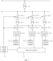
- FIG. 1 is a schematic diagram of a structure of a power system according to an embodiment of this application.
- the power system includes direct current sources 50_1 to 50_3, first transformers 40_1 to 40_3, control switches 321_1 to 322_3, the converter subarrays 20_1 to 20_3, a first alternating current bus 60, and a black start controller 11.
- the converter subarray 20_1 is disposed to correspond with the direct current source 50_1, the first transformer 40_1, and the control switches 321_1 and 322_1.
- An input port of the converter subarray 20_1 is connected to the direct current source 50_1, an output port of the converter subarray 20_1 is connected to an input end of the first transformer 40_1 through the control switch 321_1, and an output end of the first transformer 40_1 is connected to the first alternating current bus 60 through the control switch 322_1.
- the converter subarray 20_2 is disposed to correspond with the direct current source 50_2, the first transformer 40_2, and the control switches 321_2 and 322_2.
- An input port of the converter subarray 20_2 is connected to the direct current source 50_2, an output port of the converter subarray 20_2 is connected to an input end of the first transformer 40_2 through the control switch 321_2, and an output end of the first transformer 40_2 is connected to the first alternating current bus 60 through the control switch 322_2.
- the converter subarray 20_3 is disposed to correspond with the direct current source 50_3, the first transformer 40_3, and the control switches 321_3 and 322_3.
- An input port of the converter subarray 20_3 is connected to the direct current source 50_3, an output port of the converter subarray 20_3 is connected to an input end of the first transformer 40_3 through the control switch 321_3, and an output end of the first transformer 40_3 is connected to the first alternating current bus 60 through the control switch 322_3.
- the first alternating current bus 60 may be further connected to another transformer or transmission line, to form a power grid or a microgrid.
- the power system further includes a second transformer 70 and a second alternating current bus 80, and is connected to a transmission line through the second alternating current bus 80, to form a power grid or a microgrid.
- the n th target bus alternating voltage is converted by the second transformer 70 to generate an n th second bus alternating voltage.
- the first target bus alternating voltage is converted by the second transformer 70 to generate a 1 st second bus alternating voltage.
- the second target bus alternating voltage is converted by the second transformer 70 to generate a 2 nd second bus alternating voltage.
- the third target bus alternating voltage is converted by the second transformer 70 to generate a 3 rd second bus alternating voltage.
- the N th target bus alternating voltage is converted by the second transformer 70 to generate an N th second bus alternating voltage, and the N th second bus alternating voltage is a rated voltage on the second alternating current bus 80.
- the power system in this application is applicable to scenarios such as a photovoltaic power generation system, an energy storage power station, and a microgrid.
- the converter subarray may include a converter and a monitor.
- the converter may have a drive controller, and a switching frequency of a switch in the converter is controlled by using the drive controller, so that the converter converts electric energy in a direct current source into a power frequency (for example, 50 Hz) alternating current.
- a power frequency for example, 50 Hz
- the direct current source may be set to an energy storage apparatus.
- the converter is an energy storage converter
- the converter subarray is an energy storage converter subarray
- the energy storage converter may convert electric energy in the energy storage apparatus into a power frequency (for example, 50 Hz) alternating current.
- the direct current source may be set to a photovoltaic power generation apparatus.
- the converter is a photovoltaic converter
- the converter subarray is a photovoltaic converter subarray
- the photovoltaic converter may convert electric energy in the photovoltaic power generation apparatus into a power frequency (for example, 50 Hz) alternating current.
- a power frequency is generally a mains frequency. In China, the power frequency is 50 Hz. In other countries, the power frequency is 60 Hz. If a frequency of the power frequency alternating current is 50 Hz, a power frequency cycle is 0.02 seconds.
- the power system further includes a switch control module 12, and a first controller is further communicatively connected to the switch control module 12.
- the switch control module 12 is separately connected to the control switches 321_1 to 322_3.
- the first controller is further configured to send an identifier (for example, an ID) of each of the plurality of converter subarrays to the switch control module.
- the switch control module 12 is configured to: first control the control switches 321_1 to 322_3 connected to the converter subarrays 20_1 to 20_3 to be turned on, so that an output port of each converter in the converter subarray 20_1 and the input end of the first transformer 40_1 are connected in a parallel manner, an output port of each converter in the converter subarray 20_2 and the input end of the first transformer 40_2 are connected in a parallel manner, and an output port of each converter in the converter subarray 20_3 and the input end of the first transformer 40_3 are connected in a parallel manner.
- output ends of the first transformers 40_1 to 40_3 and the first alternating current bus 60 are connected in a parallel manner. In this way, the converters in the converter subarrays and an alternating current power grid that needs to be started and run can be connected to each other on a circuit.
- the black start controller 11 is configured to sequentially perform working processes of a first voltage adjustment phase to an N th voltage adjustment phase after controlling the control switches 321_1 to 322_3 to be turned on and controlling a converter in each of the converter subarrays 20_1 to 20_3 to be powered on.
- the black start controller 11 synchronously sends an n th target voltage adjustment instruction to each of the converter subarrays 20_1 to 20_3, to control each converter in each of the converter subarrays 20_1 to 20_3 to establish an n th target alternating voltage, so that the n th target alternating voltage is converted by the corresponding first transformer into an n th target bus alternating voltage input to the first alternating current bus 60.
- the black start controller 11 synchronously sends a first target voltage adjustment instruction to the converter subarrays 20_1 to 20_3.
- Each converter in the converter subarrays 20_1 to 20_3 may establish a first target alternating voltage based on the first target voltage adjustment instruction.
- the first target alternating voltage is converted by the corresponding first transformers 40_1 to 40_3 into a first target bus alternating voltage output to the first alternating current bus 60.
- the black start controller 11 synchronously sends a second target voltage adjustment instruction to the converter subarrays 20_1 to 20_3.
- Each converter in the converter subarrays 20_1 to 20_3 may establish a second target alternating voltage based on the second target voltage adjustment instruction.
- the second target alternating voltage is converted by the corresponding first transformers 40_1 to 40_3 into a second target bus alternating voltage output to the first alternating current bus 60.
- the rest may be deduced by analogy, and details are not described herein again.
- the second target alternating voltage is greater than the first target alternating voltage
- a third target alternating voltage is greater than the second target alternating voltage
- the N th target alternating voltage is greater than an (N-1) th target alternating voltage
- the second target bus alternating voltage is greater than the first target bus alternating voltage
- a third target bus alternating voltage is greater than the second target bus alternating voltage
- the N th target bus alternating voltage is greater than an (N-1) th target bus alternating voltage
- the N th target bus alternating voltage is a rated alternating voltage of the first alternating current bus 60.
- a process of establishing the rated voltage of the first alternating current bus 60 is divided into a plurality of phases. In each phase, a voltage is increased by a specific amplitude, and this process repeats until the rated voltage is established, to help a power grid establish a voltage and recover operation of a power system.
- a problem of a circulating current between subarrays in a black start process of a plurality of converter subarrays in a power station or microgrid system can be resolved, reliability of a black start of the power grid can be improved, and an application scenario of the black start of a plurality of converter subarrays can be enhanced, especially a black start scenario of a transmission line with a large reactive power.
- the black start controller 11 is further configured to control each converter in the converter subarrays 20_1 to 20_3 to be powered on, so that each converter in the converter subarrays 20_1 to 20_3 is already powered on or available before a black start is implemented.
- FIG. 2 is a schematic diagram of a voltage adjustment phase according to an embodiment of this application.
- T 1 represents the first voltage adjustment phase
- T2 represents the second voltage adjustment phase
- T 3 represents a third voltage adjustment phase, ...
- T N represents the N th voltage adjustment phase
- t 1 represents a start moment of the first voltage adjustment phase
- t 2 represents a start moment of the second voltage adjustment phase
- t 3 represents a start moment of the third voltage adjustment phase
- t N represents a start moment of the N th voltage adjustment phase.
- the first voltage adjustment phase T 1 to the N th voltage adjustment phase T N there is an interval between start moments of every two adjacent voltage adjustment phases, and the interval is greater than one power frequency cycle.
- interval t 2 -t 1 between the start moment t 2 of the second voltage adjustment phase T 2 and the start moment t 1 of the first voltage adjustment phase T 1
- t 2 -t 1 is greater than one power frequency cycle
- interval t 3 -t 2 between the start moment t 3 of the third voltage adjustment phase T 3 and the start moment t 2 of the second voltage adjustment phase T 2
- t 3 -t 2 is greater than one power frequency cycle
- interval t N -t N-1 between the start moment t N of the N th voltage adjustment phase T N and the start moment t N-1 of the (N-1) th voltage adjustment phase T N
- t N -t N-1 is greater than one power frequency cycle.
- intervals between start moments of every two adjacent voltage adjustment phases are the same.
- the interval t 2 -t 1 , the interval t 3 -t 2 , ..., and the interval t N -t N-1 are the same.
- the interval is K times the power frequency cycle.
- K the interval t 2 -t 1 , the interval t 3 -t 2 , ..., and the interval t N -t N-1 each are twice the power frequency cycle.
- K a specific value of K may be determined according to an actual application requirement. This is not limited herein.
- At least some voltage differences in voltage differences between target alternating voltages in every two adjacent voltage adjustment phases are the same.
- absolute values of at least some voltage differences in absolute values of voltage differences between target alternating voltages in every two adjacent voltage adjustment phases are the same.
- absolute values of at least some voltage differences in absolute values of voltage differences between target alternating voltages in every two adjacent voltage adjustment phases may be the same.
- an absolute value of a voltage difference between the first target alternating voltage and the second target alternating voltage is the same as an absolute value of a voltage difference between the second target alternating voltage and the third target alternating voltage.
- the absolute value of the voltage difference between the second target alternating voltage and the third target alternating voltage is the same as an absolute value of a voltage difference between the third target alternating voltage and the fourth target alternating voltage.
- the absolute value of the voltage difference between the third target alternating voltage and the fourth target alternating voltage is the same as an absolute value of a voltage difference between the fourth target alternating voltage and the fifth target alternating voltage.
- the absolute value of the voltage difference between the fourth target alternating voltage and the fifth target alternating voltage is the same as an absolute value of a voltage difference between the fifth target alternating voltage and the sixth target alternating voltage. The rest may be deduced by analogy, and details are not described herein again.
- voltage differences between target alternating voltages in every two adjacent voltage adjustment phases may alternatively be the same.
- the absolute value of the voltage difference between the first target alternating voltage and the second target alternating voltage, the absolute value of the voltage difference between the second target alternating voltage and the third target alternating voltage, and the absolute value of the voltage difference between the third target alternating voltage and the fourth target alternating voltage, the absolute value of the voltage difference between the fourth target alternating voltage and the fifth target alternating voltage, the absolute value of the voltage difference between the fifth target alternating voltage and the sixth target alternating voltage are the same. The rest may be deduced by analogy, and details are not described herein again.
- voltage differences between target alternating voltages in every two adjacent voltage adjustment phases sequentially increase.
- absolute values of voltage differences between target alternating voltages in every two adjacent voltage adjustment phases sequentially increase.
- an absolute value of a voltage difference between the first target alternating voltage and the second target alternating voltage is less than an absolute value of a voltage difference between the second target alternating voltage and the third target alternating voltage.
- the absolute value of the voltage difference between the second target alternating voltage and the third target alternating voltage is less than an absolute value of a voltage difference between the third target alternating voltage and the fourth target alternating voltage.
- the absolute value of the voltage difference between the third target alternating voltage and the fourth target alternating voltage is less than an absolute value of a voltage difference between the fourth target alternating voltage and the fifth target alternating voltage.
- An absolute value of a voltage difference between the fifth target alternating voltage and the sixth target alternating voltage is less than an absolute value of a voltage difference between the sixth target alternating voltage and the seventh target alternating voltage.
- voltage differences between target alternating voltages in every two adjacent voltage adjustment phases sequentially decrease.
- absolute values of voltage differences between target alternating voltages in every two adjacent voltage adjustment phases sequentially decrease.
- an absolute value of a voltage difference between the first target alternating voltage and the second target alternating voltage is greater than an absolute value of a voltage difference between the second target alternating voltage and the third target alternating voltage.
- the absolute value of the voltage difference between the second target alternating voltage and the third target alternating voltage is greater than an absolute value of a voltage difference between the third target alternating voltage and the fourth target alternating voltage.
- the absolute value of the voltage difference between the third target alternating voltage and the fourth target alternating voltage is greater than an absolute value of a voltage difference between the fourth target alternating voltage and the fifth target alternating voltage.
- An absolute value of a voltage difference between the fifth target alternating voltage and the sixth target alternating voltage is greater than an absolute value of a voltage difference between the sixth target alternating voltage and the seventh target alternating voltage.
- FIG. 3 is a schematic diagram of a structure of a black start controller in a power system according to an embodiment of this application.
- the black start controller 11 includes a first controller 111.
- the first controller 111 is used as an upper-layer controller, or referred to as a station or power station controller, or a micro grid controller, and can control all converter subarrays to implement corresponding control functions.
- the first controller provided in this application may be a primary controller.
- a working principle and a specific implementation of the primary controller are the same as the principle and the implementation of the first controller in this application. Therefore, for an implementation of the primary controller, refer to the specific implementation of the first controller in this application. Details are not described herein again.
- the power system may further have a monitor system.
- the monitor system may monitor an active power, a reactive power, a voltage, a current, a frequency, and the like of a converter subarray.
- the first controller 111 may be communicatively connected to the monitor system, and obtain information such as an active power, a reactive power, a voltage, a current, and a frequency of a converter subarray from the monitor system.
- the controller further includes second controllers 112_1 to 112_3.
- the first controller 111 is communicatively connected to the second controllers 112_1 to 112_3.
- the second controller 112_1 and the converter subarray 20_1 are disposed in correspondence, and the second controller 112_1 is communicatively connected to a drive controller in a converter in the converter subarray 20_1.
- the second controller 112_2 and the converter subarray 20_2 are disposed in correspondence, and the second controller 112_2 is communicatively connected to a drive controller in a converter in the converter subarray 20_2.
- the second controller 112_3 and the converter subarray 20_3 are disposed in correspondence, and the second controller 112_3 is communicatively connected to a drive controller in a converter in the converter subarray 20_3.
- the second controller 112_1 and the converter subarray 20_1 may be disposed in a same area.
- the second controller 112_1 is disposed in an operation area in which the converter subarray 20_1 is located.
- the second controller 112_2 and the converter subarray 20_2 may be disposed in a same area.
- the second controller 112_2 is disposed in an operation area in which the converter subarray 20_2 is located.
- the second controller 112_3 and the converter subarray 20_3 may be disposed in a same area.
- the second controller 112_3 is disposed in an operation area in which the converter subarray 20_3 is located.
- an uninterrupted power supply (Uninterrupted Power Supply, UPS) is further disposed in the power system, and the UPS is separately connected to the switch control module and the second controller, and is configured to store electric energy transmitted on a power grid before the power grid or an electric device is powered off, and provide the stored electric energy to the switch control module and the second controller when the power grid or the electric device is powered off, to implement a black start.
- the power system further includes a power module bridged between the UPS and the switch control module and the second controller, and the UPS may supply power to the switch control module and the second controller by using the power module.
- the first controller 111, the second controller 112_1 to 112_3, the drive controller, and the switch control module each may have a communication component for communicating with an external device or an external server.
- the communication component may include network communication protocol modules such as a Wi-Fi module and a wired Ethernet communication protocol module, so that the first controller 111 can implement communication of a control signal and a data signal with the external device or the external server.
- the communication component of the first controller 111 is communicatively connected to the communication component of each of the second controllers 112_1 to 112_3 and the switch control module, so that the first controller 111 implements communication of a control signal and a data signal with each of the second controllers 112_1 to 112_3 and the switch control module.
- the communication components of the second controllers 112_1 to 112_3 are communicatively connected to the communication component of the drive controller, so that the second controllers 112_1 to 112_3 implement communication of a control signal and a data signal with the drive controller.
- a staff inputs a black start enabling instruction to the first controller 111.
- the first controller 111 selects the converter subarrays 20_1 to 20_3 participating in a black start, and determines that the selected converter subarrays 20_1 to 20_3 are powered on or available. Then, the first controller 111 sends an initial black start preparation instruction to the second controllers 112_1 to 112_3, and the second controllers 112_1 to 112_3 send a target black start preparation instruction to a drive controller in a converter in the converter subarrays 20_1 to 20_3 based on the received initial black start preparation instruction.
- the drive controller in the converter in the converter subarrays 20_1 to 20_3 completes preparation, the drive controller sends an initial black start preparation completion instruction to the second controllers 112_1 to 112_3.
- the second controllers 112_1 to 112_3 send a target black start preparation completion instruction to the first controller 111 based on the initial black start preparation completion instruction.
- the first controller 111 may start to sequentially perform working processes of the first voltage adjustment phase to the N th voltage adjustment phase.
- a staff may alternatively input a black start enabling instruction to the first controller 111 by using an upper-level controller.
- the first controller 111 selects the converter subarrays 20_1 to 20_3 participating in a black start, and determines that the selected converter subarrays 20_1 to 20_3 are powered on or available. Then, the first controller 111 sends an initial black start preparation instruction to the second controllers 112_1 to 112_3, and the second controllers 112_1 to 112_3 send a target black start preparation instruction to a drive controller in a converter in the converter subarrays 20_1 to 20_3 based on the received initial black start preparation instruction.
- the drive controller in the converter in the converter subarrays 20_1 to 20_3 completes preparation, the drive controller sends an initial black start preparation completion instruction to the second controllers 112_1 to 112_3.
- the second controllers 112_1 to 112_3 send a target black start preparation completion instruction to the first controller 111 based on the initial black start preparation completion instruction.
- the first controller 111 may start to sequentially perform working processes of the first voltage adjustment phase to the N th voltage adjustment phase.
- the second controller may be further configured to monitor operating status information in the corresponding converter subarray, for example, a voltage, a current, a frequency, and a power (active power and reactive power) of a converter in the converter subarray.
- the first controller 111 may obtain the information such as the voltage, the current, the frequency, and the power (active power and reactive power) of the converter subarray from the second controller.
- the first controller 111 stores a pre-established adjustment sequence.
- the adjustment sequence has a first piece of target alternating voltage data to an N th piece of target alternating voltage data that are sequentially arranged.
- the adjustment sequence may be ⁇ U 1 , U 2 , U 3 , ..., U N ⁇ .
- U 1 represents the first piece of target alternating voltage data
- U 2 represents the second piece of target alternating voltage data
- U 3 represents the third piece of target alternating voltage data
- ..., and U N represents the N th piece of target alternating voltage data.
- 0.25U 4 is used to correspondingly establish the first target alternating voltage V 1
- 0.5U 4 is used to correspondingly establish the second target alternating voltage V 2
- 0.75U 4 is used to correspondingly establish the third target alternating voltage V 3
- U 4 is used to correspondingly establish the fourth target alternating voltage V 4
- V 1 0.25V 4
- V 2 0.5V 4
- V 3 0.75V 4
- the fourth target alternating voltage V 4 correspondingly outputs the fourth target bus alternating voltage to the first alternating current bus 60 as the rated voltage of the first alternating current bus 60.
- 0.4U 4 is used to correspondingly establish the first target alternating voltage V 1
- 0.6U 4 is used to correspondingly establish the second target alternating voltage V 2
- 0.8U 4 is used to correspondingly establish the third target alternating voltage V 3
- U 4 is used to correspondingly establish the fourth target alternating voltage V 4
- V 1 0.4V 4
- V 2 0.6V 4
- V 3 0.8V 4
- the fourth target alternating voltage V 4 correspondingly outputs the fourth target bus alternating voltage to the first alternating current bus 60 as the rated voltage of the first alternating current bus 60.
- a manner of storing the first piece of target alternating voltage data to the N th piece of target alternating voltage data is not limited in this application.
- the first piece of target alternating voltage data to the N th piece of target alternating voltage data may be stored in the first controller 111 in a binary, decimal, or hexadecimal manner.
- the first controller 111 is configured to synchronously send the first target voltage adjustment instruction to the second controllers 112_1 to 112_3 based on the first piece of target alternating voltage data (for example, 0.4U 4 ) in the pre-established adjustment sequence in the first voltage adjustment phase.
- the second controllers 112_1 to 112_3 may synchronously receive the first target voltage adjustment instruction.
- the second controller 112_1 is configured to send a first voltage output instruction to a communicatively connected drive controller in the converter subarray 20_1 based on the received first target voltage adjustment instruction.
- the drive controller in the converter subarray 20_1 is configured to control, based on the received first voltage output instruction, a converter in the converter subarray 20_1 to convert electric energy of the direct current source 50_1 into the first target alternating voltage of a power frequency alternating current, to establish the first target alternating voltage V 1 .
- the second controller 112_2 is configured to send a first voltage output instruction to a communicatively connected drive controller in the converter subarray 20_2 based on the received first target voltage adjustment instruction.
- the drive controller in the converter subarray 20_2 is configured to control, based on the received first voltage output instruction, a converter in the converter subarray 20_2 to convert electric energy of the direct current source 50_2 into the first target alternating voltage of the power frequency alternating current, to establish the first target alternating voltage V 1 .
- the second controller 112_3 is configured to send a first voltage output instruction to a communicatively connected drive controller in the converter subarray 20_3 based on the received first target voltage adjustment instruction.
- the drive controller in the converter subarray 20_3 is configured to control, based on the received first voltage output instruction, a converter in the converter subarray 20_3 to convert electric energy of the direct current source 50_3 into the first target alternating voltage of the power frequency alternating current, to establish the first target alternating voltage V 1 .
- the first controller 111 is configured to synchronously send the second target voltage adjustment instruction to the second controllers 112_1 to 112_3 based on the second piece of target alternating voltage data (for example, 0.6U 4 ) in the pre-established adjustment sequence in the second voltage adjustment phase.
- the second controllers 112_1 to 112_3 may synchronously receive the second target voltage adjustment instruction.
- the second controller 112_1 is configured to send a second voltage output instruction to a communicatively connected drive controller in the converter subarray 20_1 based on the received second target voltage adjustment instruction.
- the drive controller in the converter subarray 20_1 is configured to control, based on the received second voltage output instruction, a converter in the converter subarray 20_1 to convert electric energy of the direct current source 50_1 into the second target alternating voltage of the power frequency alternating current, to establish the second target alternating voltage V 2 .
- the second controller 112_2 is configured to send a second voltage output instruction to a communicatively connected drive controller in the converter subarray 20_2 based on the received second target voltage adjustment instruction.
- the drive controller in the converter subarray 20_2 is configured to control, based on the received second voltage output instruction, a converter in the converter subarray 20_2 to convert electric energy of the direct current source 50_2 into the second target alternating voltage of the power frequency alternating current, to establish the second target alternating voltage V 2 .
- the second controller 112_3 is configured to send a second voltage output instruction to a communicatively connected drive controller in the converter subarray 20_3 based on the received second target voltage adjustment instruction.
- the drive controller in the converter subarray 20_3 is configured to control, based on the received second voltage output instruction, a converter in the converter subarray 20_3 to convert electric energy of the direct current source 50_3 into the second target alternating voltage of the power frequency alternating current, to establish the second target alternating voltage V 2 .
- the first controller 111 is configured to synchronously send the third target voltage adjustment instruction to the second controllers 112_1 to 112_3 based on the third piece of target alternating voltage data (for example, 0.8U 4 ) in the pre-established adjustment sequence in the third voltage adjustment phase.
- the second controllers 112_1 to 112_3 may synchronously receive the third target voltage adjustment instruction.
- the second controller 112_1 is configured to send a third voltage output instruction to a communicatively connected drive controller in the converter subarray 20_1 based on the received third target voltage adjustment instruction.
- the drive controller in the converter subarray 20_1 is configured to control, based on the received third voltage output instruction, a converter in the converter subarray 20_1 to convert electric energy of the direct current source 50_1 into the third target alternating voltage of the power frequency alternating current, to establish the third target alternating voltage V 3 .
- the second controller 112_2 is configured to send a third voltage output instruction to a communicatively connected drive controller in the converter subarray 20_2 based on the received third target voltage adjustment instruction.
- the drive controller in the converter subarray 20_2 is configured to control, based on the received third voltage output instruction, a converter in the converter subarray 20_2 to convert electric energy of the direct current source 50_2 into the third target alternating voltage of the power frequency alternating current, to establish the third target alternating voltage V 3 .
- the second controller 112_3 is configured to send a third voltage output instruction to a communicatively connected drive controller in the converter subarray 20_3 based on the received third target voltage adjustment instruction.
- the drive controller in the converter subarray 20_3 is configured to control, based on the received third voltage output instruction, a converter in the converter subarray 20_3 to convert electric energy of the direct current source 50_3 into the third target alternating voltage of the power frequency alternating current, to establish the third target alternating voltage V 3 .
- the first controller 111 is configured to synchronously send the fourth target voltage adjustment instruction to the second controllers 112_1 to 112_3 based on the fourth piece of target alternating voltage data (for example, U 4 ) in the pre-established adjustment sequence in the fourth voltage adjustment phase.
- the second controllers 112_1 to 112_3 may synchronously receive the fourth target voltage adjustment instruction.
- the second controller 112_1 is configured to send a fourth voltage output instruction to a communicatively connected drive controller in the converter subarray 20_1 based on the received fourth target voltage adjustment instruction.
- the drive controller in the converter subarray 20_1 is configured to control, based on the received fourth voltage output instruction, a converter in the converter subarray 20_1 to convert electric energy of the direct current source 50_1 into the fourth target alternating voltage of the power frequency alternating current, to establish the fourth target alternating voltage V 4 .
- the second controller 112_2 is configured to send a fourth voltage output instruction to a communicatively connected drive controller in the converter subarray 20_2 based on the received fourth target voltage adjustment instruction.
- the drive controller in the converter subarray 20_2 is configured to control, based on the received fourth voltage output instruction, a converter in the converter subarray 20_2 to convert electric energy of the direct current source 50_2 into the fourth target alternating voltage of the power frequency alternating current, to establish the fourth target alternating voltage V 4 .
- the second controller 112_3 is configured to send a fourth voltage output instruction to a communicatively connected drive controller in the converter subarray 20_3 based on the received fourth target voltage adjustment instruction.
- the drive controller in the converter subarray 20_3 is configured to control, based on the received fourth voltage output instruction, a converter in the converter subarray 20_3 to convert electric energy of the direct current source 50_3 into the fourth target alternating voltage of the power frequency alternating current, to establish the fourth target alternating voltage V 4 .
- each converter in each converter subarray is disposed as a voltage source converter.
- each converter in the converter subarray 20_1 is disposed as a voltage source converter.
- the second controller 112_1 is configured to synchronously send the first voltage output instruction to the drive controller in each converter in the converter subarray 20_1, so that the drive controller in each converter in the converter subarray 20_1 controls a switching frequency of a switch in the corresponding converter based on the received first voltage output instruction, to convert electric energy of the direct current source 50_1 into the first target alternating voltage of the power frequency alternating current, and establish the first target alternating voltage V 1 .
- a process in which the second controller 112_1 controls establishment of other target alternating voltages may be deduced by analogy. Details are not described herein again.
- each converter in the converter subarray 20_2 is disposed as a voltage source converter.
- the second controller 112_2 is configured to synchronously send the first voltage output instruction to the drive controller in each converter in the converter subarray 20_2, so that the drive controller in each converter in the converter subarray 20_2 controls a switching frequency of a switch in the corresponding converter based on the received first voltage output instruction, to convert electric energy of the direct current source 50_2 into the first target alternating voltage of the power frequency alternating current, and establish the first target alternating voltage V 1 .
- a process in which the second controller 112_2 controls establishment of other target alternating voltages may be deduced by analogy. Details are not described herein again.
- each converter in the converter subarray 20_3 is disposed as a voltage source converter.
- the second controller 112_3 is configured to synchronously send the first voltage output instruction to the drive controller in each converter in the converter subarray 20_3, so that the drive controller in each converter in the converter subarray 20_3 controls a switching frequency of a switch in the corresponding converter based on the received first voltage output instruction, to convert electric energy of the direct current source 50_3 into the first target alternating voltage of the power frequency alternating current, and establish the first target alternating voltage V 1 .
- a process in which the second controller 112_3 controls establishment of other target alternating voltages may be deduced by analogy. Details are not described herein again.
- the drive controller in each converter of each converter subarray is further configured to: after controlling a corresponding converter to establish an n th target alternating voltage, control the corresponding converter to correct a phase of the established n th target alternating voltage based on an alternating voltage of an output port of a converter subarray in which the converter is located.
- the drive controller is further configured to: after controlling a corresponding converter to establish the first target alternating voltage V 1 , control the corresponding converter to correct a phase of the established first target alternating voltage V 1 based on an alternating voltage of an output port of a converter subarray in which the converter is located.
- FIG. 4A and FIG. 4B are an interaction diagram of a specific embodiment of a black start control method according to an embodiment of the present invention.
- the second controller 112_1 and the converter subarray 20_1 are used as an example for illustration.
- the black start control method provided in this embodiment of this application may include the following steps.
- a staff may input a black start enabling instruction to the first controller 111 by using an upper-level controller, and the first controller 111 may receive the black start enabling instruction output by the upper-level controller, and after receiving the black start enabling instruction output by the upper-level controller, may select converter subarrays participating in a black start.
- the selected converter subarrays participating in the black start are 20_1 to 20_3.
- the first controller 111 sends IDs of the selected converter subarrays 20_1 to 20_3 participating in the black start to the switch control module 12.
- the switch control module 12 controls the control switches 321_1 to 322_3 connected to the converter subarrays 20_1 to 20_3 to be turned on, to connects, on a circuit, converters in the converter subarrays 20_1 to 20_3 and an alternating current power grid that needs to be started and run. Then, the first controller 111 synchronously sends a subarray start instruction to the second controllers 112_1 to 112_3 corresponding to the converter subarrays 20_1 to 20_3.
- the second controller 112_1 sends a converter power-on instruction to a drive controller in each converter in the converter subarray 20_1 based on the received subarray start instruction.
- the drive controller in each converter in the converter subarray 20_1 controls, based on the received converter power-on instruction, the converter to be powered on, so that each converter in the converter subarray 20_1 is already powered on or available before the black start is implemented.
- the second controller 112_2 sends a converter power-on instruction to a drive controller in each converter in the converter subarray 20_2 based on the received subarray start instruction.
- the drive controller in each converter in the converter subarray 20_2 controls, based on the received converter power-on instruction, the converter to be powered on, so that each converter in the converter subarray 20_2 is already powered on or available before the black start is implemented.
- the second controller 112_3 sends a converter power-on instruction to a drive controller in each converter in the converter subarray 20_3 based on the received subarray start instruction.
- the drive controller in each converter in the converter subarray 20_3 controls, based on the received converter power-on instruction, the converter to be powered on, so that each converter in the converter subarray 20_3 is already powered on or available before the black start is implemented.
- the first controller 111 sends an initial black start preparation instruction to the second controllers 112_1 to 112_3.
- the second controllers 112_1 to 112_3 send a target black start preparation instruction to a drive controller in a converter in the converter subarrays 20_1 to 20_3 based on the received initial black start preparation instruction.
- the second controllers 112_1 to 112_3 send a target black start preparation completion instruction to the first controller 111 based on the initial black start preparation completion instruction. After receiving the target black start preparation complete instruction, the first controller 111 may start to sequentially perform working processes of a first voltage adjustment phase to an N th voltage adjustment phase.
- the first controller 111 synchronously sends a first target voltage adjustment instruction to the second controllers 112_1 to 112_3 based on a first piece of target alternating voltage data (for example, 0.4U 4 ) in a pre-established adjustment sequence in the first voltage adjustment phase.
- the second controllers 112_1 to 112_3 may synchronously receive the first target voltage adjustment instruction.
- the second controller 112_1 synchronously sends a first voltage output instruction to the drive controller in each converter in the converter subarray 20_1 based on the received first target voltage adjustment instruction.
- the second controller 112_2 synchronously sends a first voltage output instruction to the drive controller in each converter in the converter subarray 20_2 based on the received first target voltage adjustment instruction.
- the second controller 112_3 synchronously sends a first voltage output instruction to the drive controller in each converter in the converter subarray 20_3 based on the received first target voltage adjustment instruction.
- the drive controller in each converter in the converter subarray 20_1 controls a switching frequency of a switch in the corresponding converter based on the received first voltage output instruction to convert electric energy of the direct current source 50_1 into a first target alternating voltage V 1 of a power frequency alternating current, to establish the first target alternating voltage V 1 .
- the first target alternating voltage V 1 is converted by the first transformer 40_1 into a first target bus alternating voltage output to the first alternating current bus 60.
- the drive controller in each converter in the converter subarray 20_2 controls a switching frequency of a switch in the corresponding converter based on the received first voltage output instruction to convert electric energy of the direct current source 50_2 into a first target alternating voltage V 1 of the power frequency alternating current, to establish the first target alternating voltage V 1 .
- the first target alternating voltage V 1 is converted by the first transformer 40_2 into a first target bus alternating voltage output to the first alternating current bus 60.
- the drive controller in each converter in the converter subarray 20_3 controls a switching frequency of a switch in the corresponding converter based on the received first voltage output instruction to convert electric energy of the direct current source 50_3 into a first target alternating voltage V 1 of the power frequency alternating current, to establish the first target alternating voltage V 1 .
- the first target alternating voltage V 1 is converted by the first transformer 40_3 into a first target bus alternating voltage output to the first alternating current bus 60.
- S34 The drive controller in each converter in the converter subarray 20_1 controls the corresponding converter to correct a phase of the established first target alternating voltage V 1 based on an alternating voltage of an output port of the converter subarray in which the corresponding converter is located.
- the drive controller in each converter in the converter subarray 20_2 controls the corresponding converter to correct a phase of the established first target alternating voltage V 1 based on an alternating voltage of an output port of the converter subarray in which the corresponding converter is located.
- the drive controller in each converter in the converter subarray 20_3 controls the corresponding converter to correct a phase of the established first target alternating voltage V 1 based on an alternating voltage of an output port of the converter subarray in which the corresponding converter is located.
- the first controller 111 synchronously sends a second target voltage adjustment instruction to the second controllers 112_1 to 112_3 based on a second piece of target alternating voltage data (for example, 0.6U 4 ) in the pre-established adjustment sequence in the second voltage adjustment phase.
- the second controllers 112_1 to 112_3 may synchronously receive the second target voltage adjustment instruction.
- the second controller 112_1 synchronously sends a second voltage output instruction to the drive controller in each converter in the converter subarray 20_1 based on the received second target voltage adjustment instruction.
- the second controller 112_2 synchronously sends a second voltage output instruction to the drive controller in each converter in the converter subarray 20_2 based on the received second target voltage adjustment instruction.
- the second controller 112_3 synchronously sends a second voltage output instruction to the drive controller in each converter in the converter subarray 20_3 based on the received second target voltage adjustment instruction.
- the drive controller in each converter in the converter subarray 20_1 controls a switching frequency of a switch in the corresponding converter based on the received second voltage output instruction to convert electric energy of the direct current source 50_1 into a second target alternating voltage V 2 of the power frequency alternating current, to establish the second target alternating voltage V 2 .
- the second target alternating voltage V 2 is converted by the first transformer 40_1 into a second target bus alternating voltage output to the first alternating current bus 60.
- the drive controller in each converter in the converter subarray 20_2 controls a switching frequency of a switch in the corresponding converter based on the received second voltage output instruction to convert electric energy of the direct current source 50_2 into a second target alternating voltage V 2 of the power frequency alternating current, to establish the second target alternating voltage V 2 .
- the second target alternating voltage V 2 is converted by the first transformer 40_2 into a second target bus alternating voltage output to the first alternating current bus 60.
- the drive controller in each converter in the converter subarray 20_3 controls a switching frequency of a switch in the corresponding converter based on the received second voltage output instruction to convert electric energy of the direct current source 50_3 into a second target alternating voltage V 2 of the power frequency alternating current, to establish the second target alternating voltage V 2 .
- the second target alternating voltage V 2 is converted by the first transformer 40_3 into a second target bus alternating voltage output to the first alternating current bus 60.
- the drive controller in each converter in the converter subarray 20_1 controls the corresponding converter to correct a phase of the established second target alternating voltage V 2 based on an alternating voltage of an output port of the converter subarray in which the corresponding converter is located.
- the drive controller in each converter in the converter subarray 20_2 controls the corresponding converter to correct a phase of the established second target alternating voltage V 2 based on an alternating voltage of an output port of the converter subarray in which the corresponding converter is located.
- the drive controller in each converter in the converter subarray 20_3 controls the corresponding converter to correct a phase of the established second target alternating voltage V 2 based on an alternating voltage of an output port of the converter subarray in which the corresponding converter is located.
- the first controller 111 synchronously sends a third target voltage adjustment instruction to the second controllers 112_1 to 112_3 based on a third piece of target alternating voltage data (for example, 0.8U 4 ) in the pre-established adjustment sequence in the third voltage adjustment phase.
- the second controllers 112_1 to 112_3 may synchronously receive the third target voltage adjustment instruction.
- the second controller 112_1 synchronously sends a third voltage output instruction to the drive controller in each converter in the converter subarray 20_1 based on the received third target voltage adjustment instruction.
- the second controller 112_2 synchronously sends a third voltage output instruction to the drive controller in each converter in the converter subarray 20_2 based on the received third target voltage adjustment instruction.
- the second controller 112_3 synchronously sends a third voltage output instruction to the drive controller in each converter in the converter subarray 20_3 based on the received third target voltage adjustment instruction.
- the drive controller in each converter in the converter subarray 20_1 controls a switching frequency of a switch in the corresponding converter based on the received third voltage output instruction to convert electric energy of the direct current source 50_1 into a third target alternating voltage V 3 of the power frequency alternating current, to establish the third target alternating voltage V 3 .
- the third target alternating voltage V 3 is converted by the first transformer 40_1 into a third target bus alternating voltage output to the first alternating current bus 60.
- the drive controller in each converter in the converter subarray 20_2 controls a switching frequency of a switch in the corresponding converter based on the received third voltage output instruction to convert electric energy of the direct current source 50_2 into a third target alternating voltage V 3 of the power frequency alternating current, to establish the third target alternating voltage V 3 .
- the third target alternating voltage V 3 is converted by the first transformer 40_2 into a third target bus alternating voltage output to the first alternating current bus 60.
- the drive controller in each converter in the converter subarray 20_3 controls a switching frequency of a switch in the corresponding converter based on the received third voltage output instruction to convert electric energy of the direct current source 50_3 into a third target alternating voltage V 3 of the power frequency alternating current, to establish the third target alternating voltage V 3 .
- the third target alternating voltage V 3 is converted by the first transformer 40_3 into a third target bus alternating voltage output to the first alternating current bus 60.
- the drive controller in each converter in the converter subarray 20_1 controls the corresponding converter to correct a phase of the established third target alternating voltage V 3 based on an alternating voltage of an output port of the converter subarray in which the corresponding converter is located.
- the drive controller in each converter in the converter subarray 20_2 controls the corresponding converter to correct a phase of the established third target alternating voltage V 3 based on an alternating voltage of an output port of the converter subarray in which the corresponding converter is located.
- the drive controller in each converter in the converter subarray 20_3 controls the corresponding converter to correct a phase of the established third target alternating voltage V 3 based on an alternating voltage of an output port of the converter subarray in which the corresponding converter is located.
- the first controller 111 synchronously sends a fourth target voltage adjustment instruction to the second controllers 112_1 to 112_3 based on a fourth piece of target alternating voltage data (for example, U 4 ) in the pre-established adjustment sequence in the fourth voltage adjustment phase.
- the second controllers 112_1 to 112_3 may synchronously receive the fourth target voltage adjustment instruction.
- the second controller 112_1 synchronously sends a fourth voltage output instruction to the drive controller in each converter in the converter subarray 20_1 based on the received fourth target voltage adjustment instruction.
- the second controller 112_2 synchronously sends a fourth voltage output instruction to the drive controller in each converter in the converter subarray 20_2 based on the received fourth target voltage adjustment instruction.
- the second controller 112_3 synchronously sends a fourth voltage output instruction to the drive controller in each converter in the converter subarray 20_3 based on the received fourth target voltage adjustment instruction.
- the drive controller in each converter in the converter subarray 20_1 controls a switching frequency of a switch in the corresponding converter based on the received fourth voltage output instruction to convert electric energy of the direct current source 50_1 into a fourth target alternating voltage V 4 of the power frequency alternating current, to establish the fourth target alternating voltage V 4 .
- the fourth target alternating voltage V 4 is converted by the first transformer 40_1 into a fourth target bus alternating voltage output to the first alternating current bus 60.
- the drive controller in each converter in the converter subarray 20_2 controls a switching frequency of a switch in the corresponding converter based on the received fourth voltage output instruction to convert electric energy of the direct current source 50_2 into a fourth target alternating voltage V 4 of the power frequency alternating current, to establish the fourth target alternating voltage V 4 .
- the fourth target alternating voltage V 4 is converted by the first transformer 40_2 into a fourth target bus alternating voltage output to the first alternating current bus 60.
- the drive controller in each converter in the converter subarray 20_3 controls a switching frequency of a switch in the corresponding converter based on the received fourth voltage output instruction to convert electric energy of the direct current source 50_3 into a fourth target alternating voltage V 4 of the power frequency alternating current, to establish the fourth target alternating voltage V 4 .
- the fourth target alternating voltage V 4 is converted by the first transformer 40_3 into a fourth target bus alternating voltage output to the first alternating current bus 60.
- the drive controller in each converter in the converter subarray 20_1 controls the corresponding converter to correct a phase of the established fourth target alternating voltage V 4 based on an alternating voltage of an output port of the converter subarray in which the corresponding converter is located.
- the drive controller in each converter in the converter subarray 20_2 controls the corresponding converter to correct a phase of the established fourth target alternating voltage V 4 based on an alternating voltage of an output port of the converter subarray in which the corresponding converter is located.
- the drive controller in each converter in the converter subarray 20_3 controls the corresponding converter to correct a phase of the established fourth target alternating voltage V 4 based on an alternating voltage of an output port of the converter subarray in which the corresponding converter is located.
- the adjustment sequence further includes one or more pieces of power equalization control data.
- the n th piece of target alternating voltage data corresponds to and adjacent to a q th piece of power equalization control data, and the n th piece of target alternating voltage data is set before the q th piece of power equalization control data.
- the adjustment sequence includes a plurality of pieces of power equalization control data. If the adjustment sequence includes Q pieces of power equalization control data, the adjustment sequence includes a first piece of power equalization control data to a Q th piece of power equalization control data.
- Q is an integer greater than 1
- q is a positive integer, and 1 ⁇ q ⁇ Q.
- a quantity of pieces of the power equalization control data is the same as a quantity of pieces of the target alternating voltage data.
- the adjustment sequence includes the first piece of target alternating voltage data, the first piece of power equalization control data, the second piece of target alternating voltage data, the second piece of power equalization control data, the third piece of target alternating voltage data, the third piece of power equalization control data, ..., the N th piece of target alternating voltage data, and the Q th piece of power equalization control data.
- the adjustment sequence may be ⁇ U 1 , Dp 1 , U 2 , Dp 2 , U 3 , Dp 3 , ..., U N , Dp Q ⁇ .
- Dp 1 represents the first piece of power equalization control data
- Dp 2 represents the second piece of power equalization control data
- Dp 3 represents the third piece of power equalization control data
- Dp Q represents the Q th piece of power equalization control data.
- the adjustment sequence may be ⁇ U 1 , Dp 1 , U 2 , Dp 2 , U 3 , Dp 3 , U 4 , Dp 4 ⁇ .
- U 1 0.25U 4
- U 2 0.5U 4
- U 3 0.75U 4
- the adjustment sequence may also be ⁇ 0.25U 4 , Dp 1 , 0.5U 4 , Dp 2 , 0.75U 4 , Dp 3 , U 4 , Dp 4 ⁇ .
- the adjustment sequence may be ⁇ U 1 , Dp 1 , U 2 , Dp 2 , U 3 , Dp 3 , U 4 , Dp 4 ⁇ .
- U 1 0.4U 4
- U 2 0.6U 4
- U 3 0.8U 4
- the adjustment sequence may also be ⁇ 0.4U 4 , Dp 1 , 0.6U 4 , Dp 2 , 0.6U 4 , Dp 3 , U 4 , Dp 4 ⁇ .
- a quantity of pieces of the power equalization control data is less than a quantity of pieces of the target alternating voltage data.
- at least one piece of target alternating voltage data is set between two adjacent pieces of power equalization control data. In other words, Q ⁇ N.
- no power equalization control data may be set between some of the target alternating voltage data.
- the adjustment sequence may be ⁇ U 1 , Dp 1 , U 2 , U 3 , Dp 2 , U 4 , U 5 , U 6 , Dp 3 , U 7 , ..., U N , Dp N ⁇ .
- Dp 1 represents the first piece of power equalization control data
- Dp 2 represents the second piece of power equalization control data
- Dp 3 represents the third piece of power equalization control data
- Dp Q represents the Q th piece of power equalization control data.
- the adjustment sequence may be ⁇ U 1 , Dp 1 , U 2 , U 3 , Dp 2 , U 4 , Dp 3 ⁇ .
- the adjustment sequence may also be ⁇ 0.25U 4 , Dp 1 , 0.5U 4 , 0.75U 4 , Dp 2 , U 4 , Dp 3 ⁇ .
- the adjustment sequence may be ⁇ U 1 , Dp 1 , U 2 , U 3 , Dp 2 , U 4 , Dp 3 ⁇ .
- the adjustment sequence may also be ⁇ 0.4U 4 , Dp 1 , 0.6U 4 , 0.6U 4 , Dp 2 , U 4 , Dp 3 ⁇ .
- a converter in each converter subarray does not need to feed back completion to the first controller or the second controller, to reduce repeated confirmation time between the first controller or the second controller and the converter in each converter subarray, and simplify black start control complexity.
- the adjustment sequence is ⁇ U 1 , Dp 1 , U 2 , Dp 2 , U 3 , Dp 3 , ..., U N , Dp N ⁇ .
- the first controller 111 is further configured to: determine a first target power PM 1 _1 of the converter subarray 20_1, a first target power PM 1 _2 of the converter subarray 20_2, and a first target power PM 1 _3 of the converter subarray 20_3 based on the first piece of power equalization control data in the adjustment sequence; and based on the first target power PM 1 _1 of the converter subarray 20_1, the first target power PM 1 _2 of the converter subarray 20_2, and the first target power PM 1 _3 of the converter subarray 20_3, synchronously send, to the second controller 112_1, a first power adjustment instruction carrying the first target power PM 1 _1, send, to the second controller 112_2, a first power adjustment instruction carrying the first target
- the second controller 112_1 is further configured to send a first power output instruction to a communicatively connected drive controller in the converter subarray 20_1 based on the received first power adjustment instruction carrying the first target power PM 1 _1.
- the drive controller in the converter subarray 20_1 is further configured to control, based on the received first power output instruction, a corresponding converter to output the first target power PM 1 _1.
- the second controller 112_2 is further configured to send a first power output instruction to a communicatively connected drive controller in the converter subarray 20_2 based on the received first power adjustment instruction carrying the first target power PM 1 _2.
- the drive controller in the converter subarray 20_2 is further configured to control, based on the received first power output instruction, a corresponding converter to output the first target power PM 1 _2.
- the second controller 112_3 is further configured to send a first power output instruction to a communicatively connected drive controller in the converter subarray 20_3 based on the received first power adjustment instruction carrying the first target power PM 1 _3.
- the drive controller in the converter subarray 20_3 is further configured to control, based on the received first power output instruction, a corresponding converter to output the first target power PM 1 _3.
- power equalization between the converter subarrays may be controlled, so that a problem such as load power unequalization can be resolved.
- the first controller 111 is further configured to: obtain a power PM 0q _1 of an output port of the converter subarray 20_1, determine an average power value (that is, PM 0q _1/R1) of the converter subarray 20_1 based on the power PM 0q_ 1 of the output port of the converter subarray 20_1 and a quantity (for example, the quantity is R1) of converters in the converter subarray 20_1, and determine the determined average power value (that is, PM 0q _1/R1) of the converter subarray 20_1 as a q th target power PM 1 _q of the converter subarray 20_1.
- the first controller 111 is further configured to: obtain a power PM 0q _2 of an output port of the converter subarray 20_2, determine an average power value (that is, PM 0q _2/R2) of the converter subarray 20_2 based on the power PM 0q _2 of the output port of the converter subarray 20_2 and a quantity (for example, the quantity is R2) of converters in the converter subarray 20_2, and determine the determined average power value (that is, PM 0q _2/R2) of the converter subarray 20_2 as a q th target power PM 2 _q of the converter subarray 20_2.
- the first controller 111 is further configured to: obtain a power PM 0q _3 of an output port of the converter subarray 20_3, determine an average power value (that is, PM 0q _3/R3) of the converter subarray 20_3 based on the power PM 0q _3 of the output port of the converter subarray 20_3 and a quantity (for example, the quantity is R3) of converters in the converter subarray 20_3, and determine the determined average power value (that is, PM 0q _3/R3) of the converter subarray 20_3 as a q th target power PM 3 _q of the converter subarray 20_3.
- the first controller 111 may obtain a power of an output port of each converter subarray from a monitor system.
- the first controller 111 may obtain the power of the output port of each converter subarray from the first controller 111 corresponding to the converter subarray.
- FIG. 5A and FIG. 5B are an interaction diagram of a specific embodiment of a black start control method according to another embodiment of the present invention.
- the second controller 112_1 and the converter subarray 20_1 are used as an example for illustration.
- the black start control method provided in this embodiment of this application may include the following steps.
- the first controller 111 determines, based on the first piece of power equalization control data in the adjustment sequence, the first target power PM 1 _1 of the converter subarray 20_1, the first target power PM 1 _2 of the converter subarray 20_2, and the first target power PM 1 _3 of the converter subarray 20_3; and synchronously sends, to the second controller 112_1, a first power adjustment instruction carrying the first target power PM 1 _1, sends, to the second controller 112_2, the first power adjustment instruction carrying the first target power PM 1 _2, and sends, to the second controller 112_3, the first power adjustment instruction carrying the first target power PM 1 _3.
- the second controller 112_1 sends the first power output instruction to the drive controller in each converter in the converter subarray 20_1 based on the received first power adjustment instruction carrying the first target power PM 1 _1.
- the second controller 112_2 sends the first power output instruction to the drive controller in each converter in the converter subarray 20_2 based on the received first power adjustment instruction carrying the first target power PM 1 _2.
- the second controller 112_3 sends the first power output instruction to the drive controller in each converter in the converter subarray 20_3 based on the received first power adjustment instruction carrying the first target power PM 1 _3.
- the drive controller in the converter subarray 20_1 controls, based on the received first power output instruction, a corresponding converter to output the first target power PM 1 _1.
- the drive controller in the converter subarray 20_2 controls, based on the received first power output instruction, a corresponding converter to output the first target power PM 1 _2.
- the drive controller in the converter subarray 20_3 controls, based on the received first power output instruction, a corresponding converter to output the first target power PM 1 _3.
- the first controller 111 determines, based on the second piece of power equalization control data in the adjustment sequence, the second target power PM 2 _1 of the converter subarray 20_1, the second target power PM 2 _2 of the converter subarray 20_2, and the second target power PM 2 _3 of the converter subarray 20_3; and synchronously sends, to the second controller 112_1, the second power adjustment instruction carrying the second target power PM 2 _1, sends, to the second controller 112_2, the second power adjustment instruction carrying the second target power PM 2 _2, and sends, to the second controller 112_3, the second power adjustment instruction carrying the second target power PM 2 _3.
- the second controller 112_1 sends the second power output instruction to the drive controller in each converter in the converter subarray 20_1 based on the received second power adjustment instruction carrying the second target power PM 2 _1.
- the second controller 112_2 sends the second power output instruction to the drive controller in each converter in the converter subarray 20_2 based on the received second power adjustment instruction carrying the second target power PM 2 _2.
- the second controller 112_3 sends the second power output instruction to the drive controller in each converter in the converter subarray 20_3 based on the received second power adjustment instruction carrying the second target power PM 2 _3.
- the drive controller in the converter subarray 20_1 controls, based on the received second power output instruction, a corresponding converter to output the second target power PM 2 _1.
- the drive controller in the converter subarray 20_2 controls, based on the received second power output instruction, a corresponding converter to output the second target power PM 2 _2.
- the drive controller in the converter subarray 20_3 controls, based on the received second power output instruction, a corresponding converter to output the second target power PM 2 _3.
- the first controller 111 determines, based on the third piece of power equalization control data in the adjustment sequence, the third target power PM 3 _1 of the converter subarray 20_1, the third target power PM 3 _2 of the converter subarray 20_2, and the third target power PM 3 _3 of the converter subarray 20_3; and synchronously sends, to the second controller 112_1, the third power adjustment instruction carrying the third target power PM 3 _1, sends, to the second controller 112_2, the third power adjustment instruction carrying the third target power PM 3 _2, and sends, to the second controller 112_3, the third power adjustment instruction carrying the third target power PM 3 _3.
- the second controller 112_1 sends the third power output instruction to the drive controller in each converter in the converter subarray 20_1 based on the received third power adjustment instruction carrying the third target power PM 3 _1.
- the second controller 112_2 sends the third power output instruction to the drive controller in each converter in the converter subarray 20_2 based on the received third power adjustment instruction carrying the third target power PM 3 _2.
- the second controller 112_3 sends the third power output instruction to the drive controller in each converter in the converter subarray 20_3 based on the received third power adjustment instruction carrying the third target power PM 3 _3.
- the drive controller in the converter subarray 20_1 controls, based on the received third power output instruction, a corresponding converter to output the third target power PM 3 _1.
- the drive controller in the converter subarray 20_2 controls, based on the received third power output instruction, a corresponding converter to output the third target power PM 3 _2.
- the drive controller in the converter subarray 20_3 controls, based on the received third power output instruction, a corresponding converter to output the third target power PM 3 _3.
- the first controller 111 determines, based on the fourth piece of power equalization control data in the adjustment sequence, the fourth target power PM 4 _1 of the converter subarray 20_1, the fourth target power PM 4 _2 of the converter subarray 20_2, and the fourth target power PM 4 _3 of the converter subarray 20_3; and synchronously sends, to the second controller 112_1, the fourth power adjustment instruction carrying the fourth target power PN1 4 _1, sends, to the second controller 112_2, the fourth power adjustment instruction carrying the fourth target power PM 4 _2, and sends, to the second controller 112_3, the fourth power adjustment instruction carrying the fourth target power PM 4 _3.
- the second controller 112_1 sends the fourth power output instruction to the drive controller in each converter in the converter subarray 20_1 based on the received fourth power adjustment instruction carrying the fourth target power PM 4 _1.
- the second controller 112_2 sends the fourth power output instruction to the drive controller in each converter in the converter subarray 20_2 based on the received fourth power adjustment instruction carrying the fourth target power PM 4 _2.
- the second controller 112_3 sends the fourth power output instruction to the drive controller in each converter in the converter subarray 20_3 based on the received fourth power adjustment instruction carrying the fourth target power PM 4 _3.
- the drive controller in the converter subarray 20_1 controls, based on the received fourth power output instruction, a corresponding converter to output the fourth target power PM 4 _1.
- the drive controller in the converter subarray 20_2 controls, based on the received fourth power output instruction, a corresponding converter to output the fourth target power PM 4 _2.
- the drive controller in the converter subarray 20_3 controls, based on the received fourth power output instruction, a corresponding converter to output the fourth target power PM 4_ 3.
- each converter in each converter subarray is a voltage source converter.
- one converter in each converter subarray is a master converter, and other converters are slave converters.
- the second controller is further configured to send the n th voltage output instruction to a drive controller in a master converter in the corresponding converter subarray.
- the drive controller connected to the master converter is further configured to: control, based on the received n th voltage output instruction, the master converter to establish an n th target alternating voltage, and send a slave voltage output instruction to a drive controller in the slave converter based on the received n th voltage output instruction.
- the drive controller in the slave converter is configured to control, based on the received slave voltage output instruction, the slave converter to establish the n th target alternating voltage.
- one converter is a master converter, and other converters are slave converters.
- the second controller 112_1 is configured to send an n th voltage output instruction to a drive controller in the master converter in the converter subarray 20_1.
- the drive controller connected to the master converter in the converter subarray 20_1 is further configured to: control, based on a received n th voltage output instruction, the master converter to establish an n th target alternating voltage, and send a slave voltage output instruction to a drive controller in the slave converter in the converter subarray 20_1 based on the received n th voltage output instruction.
- the drive controller in the slave converter in the converter subarray 20_1 is configured to control, based on the received slave voltage output instruction, the slave converter to establish an n th target alternating voltage.
- one converter is a master converter, and other converters are slave converters.
- the second controller 112_2 is configured to send an n th voltage output instruction to a drive controller in the master converter in the converter subarray 20_2.
- the drive controller connected to the master converter in the converter subarray 20_2 is further configured to: control, based on a received n th voltage output instruction, the master converter to establish an n th target alternating voltage, and send a slave voltage output instruction to a drive controller in the slave converter in the converter subarray 20_2 based on the received n th voltage output instruction.
- the drive controller in the slave converter in the converter subarray 20_2 is configured to control, based on the received slave voltage output instruction, the slave converter to establish an n th target alternating voltage.
- one converter is a master converter, and other converters are slave converters.
- the second controller 112_3 is configured to send an n th voltage output instruction to a drive controller in the master converter in the converter subarray 20_3.
- the drive controller connected to the master converter in the converter subarray 20_3 is further configured to: control, based on a received n th voltage output instruction, the master converter to establish an n th target alternating voltage, and send a slave voltage output instruction to a drive controller in the slave converter in the converter subarray 20_3 based on the received n th voltage output instruction.
- the drive controller in the slave converter in the converter subarray 20_3 is configured to control, based on the received slave voltage output instruction, the slave converter to establish an n th target alternating voltage.
- steps S10 to S31, steps S34 to S41, steps S44 to S51, steps S54 to S61, and steps S64 to S67 refer to the foregoing descriptions. Details are not described herein again.
- step S32 is: The second controller 112_1 sends a first voltage output instruction to the drive controller in the master converter in the converter subarray 20_1 based on the received first target voltage adjustment instruction.
- the second controller 112_2 sends a first voltage output instruction to the drive controller in the master converter in the converter subarray 20_2 based on the received first target voltage adjustment instruction.
- the second controller 112_3 sends a first voltage output instruction to the drive controller in the master converter in the converter subarray 20_3 based on the received first target voltage adjustment instruction.
- Step S33 is: The drive controller in the master converter in the converter subarray 20_1 controls a switching frequency of a switch in the corresponding converter based on the received first voltage output instruction to convert electric energy of the direct current source 50_1 into a first target alternating voltage V 1 of the power frequency alternating current, to establish the first target alternating voltage V 1 .
- the master converter in the converter subarray 20_1 sends a slave voltage output instruction to the drive controller in the slave converter in the converter subarray 20_1 based on the received first voltage output instruction.
- the drive controller in the slave converter in the converter subarray 20_1 controls, based on the received slave voltage output instruction, the slave converter to establish a first target alternating voltage V 1 .
- the first target alternating voltage V 1 is converted by the first transformer 40_1 into a first target bus alternating voltage output to the first alternating current bus 60.
- the drive controller in the master converter in the converter subarray 20_2 controls a switching frequency of a switch in the corresponding converter based on the received first voltage output instruction to convert electric energy of the direct current source 50_2 into a first target alternating voltage V 1 of the power frequency alternating current, to establish the first target alternating voltage V 1 .
- the master converter in the converter subarray 20_2 sends a slave voltage output instruction to the drive controller in the slave converter in the converter subarray 20_2 based on the received first voltage output instruction.
- the drive controller in the slave converter in the converter subarray 20_2 controls, based on the received slave voltage output instruction, the slave converter to establish a first target alternating voltage V 1 .
- the first target alternating voltage V 1 is converted by the first transformer 40_2 into a first target bus alternating voltage output to the first alternating current bus 60.
- the drive controller in the master converter in the converter subarray 20_3 controls a switching frequency of a switch in the corresponding converter based on the received first voltage output instruction to convert electric energy of the direct current source 50_3 into a first target alternating voltage V 1 of the power frequency alternating current, to establish the first target alternating voltage V 1 .
- the master converter in the converter subarray 20_3 sends a slave voltage output instruction to the drive controller in the slave converter in the converter subarray 20_3 based on the received first voltage output instruction.
- the drive controller in the slave converter in the converter subarray 20_3 controls, based on the received slave voltage output instruction, the slave converter to establish a first target alternating voltage V 1 .
- the first target alternating voltage V 1 is converted by the first transformer 40_3 into a first target bus alternating voltage output to the first alternating current bus 60.
- Step S42 is: The second controller 112_1 sends a second voltage output instruction to the drive controller in the master converter in the converter subarray 20_1 based on the received second target voltage adjustment instruction.
- the second controller 112_2 sends a second voltage output instruction to the drive controller in the master converter in the converter subarray 20_2 based on the received second target voltage adjustment instruction.
- the second controller 112_3 sends a second voltage output instruction to the drive controller in the master converter in the converter subarray 20_3 based on the received second target voltage adjustment instruction.
- Step S43 is: The drive controller in the master converter in the converter subarray 20_1 controls a switching frequency of a switch in the corresponding converter based on the received second voltage output instruction to convert electric energy of the direct current source 50_1 into a second target alternating voltage V 2 of the power frequency alternating current, to establish the second target alternating voltage V 2 .
- the master converter in the converter subarray 20_1 sends a slave voltage output instruction to the drive controller in the slave converter in the converter subarray 20_1 based on the received second voltage output instruction.
- the drive controller in the slave converter in the converter subarray 20_1 controls, based on the received slave voltage output instruction, the slave converter to establish a second target alternating voltage V 2 .
- the second target alternating voltage V 2 is converted by the first transformer 40_1 into a second target bus alternating voltage output to the first alternating current bus 60.
- the drive controller in the master converter in the converter subarray 20_2 controls a switching frequency of a switch in the corresponding converter based on the received second voltage output instruction to convert electric energy of the direct current source 50_2 into a second target alternating voltage V 2 of the power frequency alternating current, to establish the second target alternating voltage V 2 .
- the master converter in the converter subarray 20_2 sends a slave voltage output instruction to the drive controller in the slave converter in the converter subarray 20_2 based on the received second voltage output instruction.
- the drive controller in the slave converter in the converter subarray 20_2 controls, based on the received slave voltage output instruction, the slave converter to establish a second target alternating voltage V 2 .
- the second target alternating voltage V 2 is converted by the first transformer 40_2 into a second target bus alternating voltage output to the first alternating current bus 60.
- the drive controller in the master converter in the converter subarray 20_3 controls a switching frequency of a switch in the corresponding converter based on the received second voltage output instruction to convert electric energy of the direct current source 50_3 into a second target alternating voltage V 2 of the power frequency alternating current, to establish the second target alternating voltage V 2 .
- the master converter in the converter subarray 20_3 sends a slave voltage output instruction to the drive controller in the slave converter in the converter subarray 20_3 based on the received second voltage output instruction.
- the drive controller in the slave converter in the converter subarray 20_3 controls, based on the received slave voltage output instruction, the slave converter to establish a second target alternating voltage V 2 .
- the second target alternating voltage V 2 is converted by the first transformer 40_3 into a second target bus alternating voltage output to the first alternating current bus 60.
- Step S52 is: The second controller 112_1 sends a third voltage output instruction to the drive controller in the master converter in the converter subarray 20_1 based on the received third target voltage adjustment instruction.
- the second controller 112_2 sends a third voltage output instruction to the drive controller in the master converter in the converter subarray 20_2 based on the received third target voltage adjustment instruction.
- the second controller 112_3 sends a third voltage output instruction to the drive controller in the master converter in the converter subarray 20_3 based on the received third target voltage adjustment instruction.
- Step S53 is: The drive controller in the master converter in the converter subarray 20_1 controls a switching frequency of a switch in the corresponding converter based on the received third voltage output instruction to convert electric energy of the direct current source 50_1 into a third target alternating voltage V 3 of the power frequency alternating current, to establish the third target alternating voltage V 3 .
- the master converter in the converter subarray 20_1 sends a slave voltage output instruction to the drive controller in the slave converter in the converter subarray 20_1 based on the received third voltage output instruction.
- the drive controller in the slave converter in the converter subarray 20_1 controls, based on the received slave voltage output instruction, the slave converter to establish a third target alternating voltage V 3 .
- the third target alternating voltage V 3 is converted by the first transformer 40_1 into a third target bus alternating voltage output to the first alternating current bus 60.
- the drive controller in the master converter in the converter subarray 20_2 controls a switching frequency of a switch in the corresponding converter based on the received third voltage output instruction to convert electric energy of the direct current source 50_2 into a third target alternating voltage V 3 of the power frequency alternating current, to establish the third target alternating voltage V 3 .
- the master converter in the converter subarray 20_2 sends a slave voltage output instruction to the drive controller in the slave converter in the converter subarray 20_2 based on the received third voltage output instruction.
- the drive controller in the slave converter in the converter subarray 20_2 controls, based on the received slave voltage output instruction, the slave converter to establish a third target alternating voltage V 3 .
- the third target alternating voltage V 3 is converted by the first transformer 40_2 into a third target bus alternating voltage output to the first alternating current bus 60.
- the drive controller in the master converter in the converter subarray 20_3 controls a switching frequency of a switch in the corresponding converter based on the received third voltage output instruction to convert electric energy of the direct current source 50_3 into a third target alternating voltage V 3 of the power frequency alternating current, to establish the third target alternating voltage V 3 .
- the master converter in the converter subarray 20_3 sends a slave voltage output instruction to the drive controller in the slave converter in the converter subarray 20_3 based on the received third voltage output instruction.
- the drive controller in the slave converter in the converter subarray 20_3 controls, based on the received slave voltage output instruction, the slave converter to establish a third target alternating voltage V 3 .
- the third target alternating voltage V 3 is converted by the first transformer 40_3 into a third target bus alternating voltage output to the first alternating current bus 60.
- Step S62 is: The second controller 112_1 sends a fourth voltage output instruction to the drive controller in the master converter in the converter subarray 20_1 based on the received fourth target voltage adjustment instruction.
- the second controller 112_2 sends a fourth voltage output instruction to the drive controller in the master converter in the converter subarray 20_2 based on the received fourth target voltage adjustment instruction.
- the second controller 112_3 sends a fourth voltage output instruction to the drive controller in the master converter in the converter subarray 20_3 based on the received fourth target voltage adjustment instruction.
- Step S63 is: The drive controller in the master converter in the converter subarray 20_1 controls a switching frequency of a switch in the corresponding converter based on the received fourth voltage output instruction to convert electric energy of the direct current source 50_1 into a fourth target alternating voltage V 4 of the power frequency alternating current, to establish the fourth target alternating voltage V 4 .
- the master converter in the converter subarray 20_1 sends a slave voltage output instruction to the drive controller in the slave converter in the converter subarray 20_1 based on the received fourth voltage output instruction.
- the drive controller in the slave converter in the converter subarray 20_1 controls, based on the received slave voltage output instruction, the slave converter to establish a fourth target alternating voltage V 4 .
- the fourth target alternating voltage V 4 is converted by the first transformer 40_1 into a fourth target bus alternating voltage output to the first alternating current bus 60.
- the drive controller in the master converter in the converter subarray 20_2 controls a switching frequency of a switch in the corresponding converter based on the received fourth voltage output instruction to convert electric energy of the direct current source 50_2 into a fourth target alternating voltage V 4 of the power frequency alternating current, to establish the fourth target alternating voltage V 4 .
- the master converter in the converter subarray 20_2 sends a slave voltage output instruction to the drive controller in the slave converter in the converter subarray 20_2 based on the received fourth voltage output instruction.
- the drive controller in the slave converter in the converter subarray 20_2 controls, based on the received slave voltage output instruction, the slave converter to establish a fourth target alternating voltage V 4 .
- the fourth target alternating voltage V 4 is converted by the first transformer 40_2 into a fourth target bus alternating voltage output to the first alternating current bus 60.
- the drive controller in the master converter in the converter subarray 20_3 controls a switching frequency of a switch in the corresponding converter based on the received fourth voltage output instruction to convert electric energy of the direct current source 50_3 into a fourth target alternating voltage V 4 of the power frequency alternating current, to establish the fourth target alternating voltage V 4 .
- the master converter in the converter subarray 20_3 sends a slave voltage output instruction to the drive controller in the slave converter in the converter subarray 20_3 based on the received fourth voltage output instruction.
- the drive controller in the slave converter in the converter subarray 20_3 controls, based on the received slave voltage output instruction, the slave converter to establish a fourth target alternating voltage V 4 .
- the fourth target alternating voltage V 4 is converted by the first transformer 40_3 into a fourth target bus alternating voltage output to the first alternating current bus 60.
- each converter subarray one converter is a voltage source converter, and other converters are current source converters.
- the second controller is further configured to send an n th voltage output instruction to a drive controller connected to the voltage source converter.
- one converter is a voltage source converter
- other converters are current source converters.
- the second controller 112_1 is further configured to send an n th voltage output instruction to a drive controller in the voltage source converter in the converter subarray 20_1.
- a voltage of an output port of a current source converter in the converter subarray 20_1 may follow a voltage of an output port of the voltage source converter.
- one converter is a voltage source converter
- other converters are current source converters.
- the second controller 112_2 is further configured to send an n th voltage output instruction to a drive controller in the voltage source converter in the converter subarray 20_2.
- a voltage of an output port of a current source converter in the converter subarray 20_2 may follow a voltage of an output port of the voltage source converter.
- one converter is a voltage source converter, and other converters are current source converters.
- the second controller 112_3 is further configured to send an n th voltage output instruction to a drive controller in the voltage source converter in the converter subarray 20_3.
- a voltage of an output port of a current source converter in the converter subarray 20_3 may follow a voltage of an output port of the voltage source converter.
- steps S10 to S31, steps S34 to S41, steps S44 to S51, steps S54 to S61, and steps S64 to S67 refer to the foregoing descriptions. Details are not described herein again.
- step S32 is: The second controller 112_1 sends a first voltage output instruction to the drive controller in the voltage source converter in the converter subarray 20_1 based on the received first target voltage adjustment instruction.
- the second controller 112_2 sends a first voltage output instruction to the drive controller in the voltage source converter in the converter subarray 20_2 based on the received first target voltage adjustment instruction.
- the second controller 112_3 sends a first voltage output instruction to the drive controller in the voltage source converter in the converter subarray 20_3 based on the received first target voltage adjustment instruction.
- Step S33 is: The drive controller in the voltage source converter in the converter subarray 20_1 controls a switching frequency of a switch in the corresponding converter based on the received first voltage output instruction to convert electric energy of the direct current source 50_1 into a first target alternating voltage V 1 of the power frequency alternating current, to establish the first target alternating voltage V 1 .
- the current source converter in the converter subarray 20_1 outputs the first target alternating voltage V 1 following the voltage source converter.
- the first target alternating voltage V 1 is converted by the first transformer 40_1 into a first target bus alternating voltage output to the first alternating current bus 60.
- the drive controller in the voltage source converter in the converter subarray 20_2 controls a switching frequency of a switch in the corresponding converter based on the received first voltage output instruction to convert electric energy of the direct current source 50_2 into a first target alternating voltage V 1 of the power frequency alternating current, to establish the first target alternating voltage V 1 .
- the current source converter in the converter subarray 20_2 outputs the first target alternating voltage V 1 following the voltage source converter.
- the first target alternating voltage V 1 is converted by the first transformer 40_2 into a first target bus alternating voltage output to the first alternating current bus 60.
- the drive controller in the voltage source converter in the converter subarray 20_3 controls a switching frequency of a switch in the corresponding converter based on the received first voltage output instruction to convert electric energy of the direct current source 50_3 into a first target alternating voltage V 1 of the power frequency alternating current, to establish the first target alternating voltage V 1 .
- the current source converter in the converter subarray 20_3 outputs the first target alternating voltage V 1 following the voltage source converter.
- the first target alternating voltage V 1 is converted by the first transformer 40_3 into a first target bus alternating voltage output to the first alternating current bus 60.
- Step S42 is: The second controller 112_1 sends a second voltage output instruction to the drive controller in the voltage source converter in the converter subarray 20_1 based on the received second target voltage adjustment instruction.
- the second controller 112_2 sends a second voltage output instruction to the drive controller in the voltage source converter in the converter subarray 20_2 based on the received second target voltage adjustment instruction.
- the second controller 112_3 sends a second voltage output instruction to the drive controller in the voltage source converter in the converter subarray 20_3 based on the received second target voltage adjustment instruction.
- Step S43 is: The drive controller in the voltage source converter in the converter subarray 20_1 controls a switching frequency of a switch in the corresponding converter based on the received second voltage output instruction to convert electric energy of the direct current source 50_1 into a second target alternating voltage V 2 of the power frequency alternating current, to establish the second target alternating voltage V 2 .
- the current source converter in the converter subarray 20_1 outputs the second target alternating voltage V 2 following the voltage source converter.
- the second target alternating voltage V 2 is converted by the first transformer 40_1 into a second target bus alternating voltage output to the first alternating current bus 60.
- the drive controller in the voltage source converter in the converter subarray 20_2 controls a switching frequency of a switch in the corresponding converter based on the received second voltage output instruction to convert electric energy of the direct current source 50_2 into a second target alternating voltage V 2 of the power frequency alternating current, to establish the second target alternating voltage V 2 .
- the current source converter in the converter subarray 20_2 outputs the second target alternating voltage V 2 following the voltage source converter.
- the second target alternating voltage V 2 is converted by the first transformer 40_2 into a second target bus alternating voltage output to the first alternating current bus 60.
- the drive controller in the voltage source converter in the converter subarray 20_3 controls a switching frequency of a switch in the corresponding converter based on the received second voltage output instruction to convert electric energy of the direct current source 50_3 into a second target alternating voltage V 2 of the power frequency alternating current, to establish the second target alternating voltage V 2 .
- the current source converter in the converter subarray 20_3 outputs the second target alternating voltage V 2 following the voltage source converter.
- the second target alternating voltage V 2 is converted by the first transformer 40_3 into a second target bus alternating voltage output to the first alternating current bus 60.
- Step S52 is: The second controller 112_1 sends a third voltage output instruction to the drive controller in the voltage source converter in the converter subarray 20_1 based on the received third target voltage adjustment instruction.
- the second controller 112_2 sends a third voltage output instruction to the drive controller in the voltage source converter in the converter subarray 20_2 based on the received third target voltage adjustment instruction.
- the second controller 112_3 sends a third voltage output instruction to the drive controller in the voltage source converter in the converter subarray 20_3 based on the received third target voltage adjustment instruction.
- Step S53 is: The drive controller in the voltage source converter in the converter subarray 20_1 controls a switching frequency of a switch in the corresponding converter based on the received third voltage output instruction to convert electric energy of the direct current source 50_1 into a third target alternating voltage V 3 of the power frequency alternating current, to establish the third target alternating voltage V 3 .
- the current source converter in the converter subarray 20_1 outputs the third target alternating voltage V 3 following the voltage source converter.
- the third target alternating voltage V 3 is converted by the first transformer 40_1 into a third target bus alternating voltage output to the first alternating current bus 60.
- the drive controller in the voltage source converter in the converter subarray 20_2 controls a switching frequency of a switch in the corresponding converter based on the received third voltage output instruction to convert electric energy of the direct current source 50_2 into a third target alternating voltage V 3 of the power frequency alternating current, to establish the third target alternating voltage V 3 .
- the current source converter in the converter subarray 20_2 outputs the third target alternating voltage V 3 following the voltage source converter.
- the third target alternating voltage V 3 is converted by the first transformer 40_2 into a third target bus alternating voltage output to the first alternating current bus 60.
- the drive controller in the voltage source converter in the converter subarray 20_3 controls a switching frequency of a switch in the corresponding converter based on the received third voltage output instruction to convert electric energy of the direct current source 50_3 into a third target alternating voltage V 3 of the power frequency alternating current, to establish the third target alternating voltage V 3 .
- the current source converter in the converter subarray 20_3 outputs the third target alternating voltage V 3 following the voltage source converter.
- the third target alternating voltage V 3 is converted by the first transformer 40_3 into a third target bus alternating voltage output to the first alternating current bus 60.
- Step S62 is: The second controller 112_1 sends a fourth voltage output instruction to the drive controller in the voltage source converter in the converter subarray 20_1 based on the received fourth target voltage adjustment instruction.
- the second controller 112_2 sends a fourth voltage output instruction to the drive controller in the voltage source converter in the converter subarray 20_2 based on the received fourth target voltage adjustment instruction.
- the second controller 112_3 sends a fourth voltage output instruction to the drive controller in the voltage source converter in the converter subarray 20_3 based on the received fourth target voltage adjustment instruction.
- Step S63 is: The drive controller in the voltage source converter in the converter subarray 20_1 controls a switching frequency of a switch in the corresponding converter based on the received fourth voltage output instruction to convert electric energy of the direct current source 50_1 into a fourth target alternating voltage V 4 of the power frequency alternating current, to establish the fourth target alternating voltage V 4 .
- the current source converter in the converter subarray 20_1 outputs the fourth target alternating voltage V 4 following the voltage source converter.
- the fourth target alternating voltage V 4 is converted by the first transformer 40_1 into a fourth target bus alternating voltage output to the first alternating current bus 60.
- the drive controller in the voltage source converter in the converter subarray 20_2 controls a switching frequency of a switch in the corresponding converter based on the received fourth voltage output instruction to convert electric energy of the direct current source 50_2 into a fourth target alternating voltage V 4 of the power frequency alternating current, to establish the fourth target alternating voltage V 4 .
- the current source converter in the converter subarray 20_2 outputs the fourth target alternating voltage V 4 following the voltage source converter.
- the fourth target alternating voltage V 4 is converted by the first transformer 40_2 into a fourth target bus alternating voltage output to the first alternating current bus 60.
- the drive controller in the voltage source converter in the converter subarray 20_3 controls a switching frequency of a switch in the corresponding converter based on the received fourth voltage output instruction to convert electric energy of the direct current source 50_3 into a fourth target alternating voltage V 4 of the power frequency alternating current, to establish the fourth target alternating voltage V 4 .
- the current source converter in the converter subarray 20_3 outputs the fourth target alternating voltage V 4 following the voltage source converter.
- the fourth target alternating voltage V 4 is converted by the first transformer 40_3 into a fourth target bus alternating voltage output to the first alternating current bus 60.
- the switch control module may also be configured to: first control control switches connected to a first part of converter subarrays in the plurality of converter subarrays to be turned on, so that an output port of each converter in each of the first part of converter subarrays and an input end of a corresponding transformer are connected in a parallel manner, and output ends of transformers corresponding to the first part of converter subarrays and the first alternating current bus are connected; then, send a start instruction to each of the first part of converter subarrays, to control each of the first part of converter subarrays to be powered on, so that each of the first part of converter subarrays is already powered on or available state before the black start is implemented; then, control control switches connected to a second part of converter subarrays in the plurality of converter subarrays to be turned on, so that an output port of each converter in each of the second part of converter subarrays and an input end of a corresponding transformer are connected in a parallel manner, and output ends of transformers corresponding to
- the first controller 111 is further configured to: after controlling each of the first part of converter subarrays to be powered on, and before controlling the control switches connected to the second part of converter subarrays in the plurality of converter subarrays to be turned on, synchronously send an initial voltage adjustment instruction to a corresponding second controller in each of the first part of converter subarrays.
- the corresponding second controller in each of the first part of converter subarrays is further configured to send the initial voltage output instruction to the communicatively connected drive controller based on the received initial voltage adjustment instruction.
- the drive controller in each of the first part of converter subarrays is further configured to control, based on the received initial voltage output instruction, a corresponding converter to establish an initial alternating voltage, so that the initial alternating voltage is converted by the first transformer into an initial bus alternating voltage input to the first alternating current bus 60.
- the initial bus alternating voltage is less than the first target bus alternating voltage.
- the initial bus alternating voltage is first established on the first alternating current bus 60 by using the first part of converter subarrays. Then, after other converter subarrays are grid-connected, the first part of converter subarrays and the second part of converter subarrays are combined to increase the voltage on the first alternating current bus 60 by phase, and power equalization control is implemented until a rated voltage is established on the first alternating current bus 60.
- a quantity of converter subarrays in the first part of converter subarrays is less than a quantity of converter subarrays in the second part of converter subarrays.
- the first part of converter subarrays include one of the plurality of converter subarrays
- the second part of converter subarrays include other converter subarrays of the plurality of converter subarrays other than the first part of converter subarrays.
- the first part of converter subarrays may include the converter subarray 20_1
- the second part of converter subarrays may include the converter subarrays 20_2 and 20_3.
- FIG. 5A and FIG. 5B For an interaction diagram of a specific embodiment of a black start control method according to still another embodiment of the present invention, refer to FIG. 5A and FIG. 5B .
- steps S21 to S67 refer to the foregoing descriptions. Details are not described herein again.
- step S10 is: A staff may input a black start enabling instruction to the first controller 111 by using an upper-level controller, and the first controller 111 may receive the black start enabling instruction output by the upper-level controller, and after receiving the black start enabling instruction output by the upper-level controller, may select converter subarrays participating in a black start.
- the selected converter subarrays participating in the black start are 20_1 to 20_3.
- the first controller 111 sends IDs of the selected converter subarrays 20_1 to 20_3 participating in the black start to the switch control module 12.
- the switch control module 12 controls the control switches 321_1 and 322_1 connected to the converter subarray 20_1 to be turned on, so that an output port of each converter in the converter subarray 20_1 and an input end of the first transformer 40_1 are connected in parallel, and an output end of the first transformer 40_1 and the first alternating current bus 60 are connected. In this way, the converter in the converter subarray 20_1 and an alternating current power grid that needs to be started and run can be connected to each other on a circuit.
- the first controller 111 sends a subarray start instruction to the second controller 112_1 corresponding to the converter subarray 20_1.
- the second controller 112_1 sends a converter power-on instruction to a drive controller in each converter in the converter subarray 20_1 based on the received subarray start instruction.
- the drive controller in each converter in the converter subarray 20_1 controls, based on the received converter power-on instruction, the converter to be powered on, so that each converter in the converter subarray 20_1 is already powered on or available before the black start is implemented.
- the first controller 111 sends an initial voltage adjustment instruction to the second controller 112_1.
- the second controller 112_1 sends an initial voltage output instruction to the drive controller in each converter in the converter subarray 20_1 based on the received initial voltage adjustment instruction.
- the drive controller in each converter in the converter subarray 20_1 controls, based on the received initial voltage output instruction, a corresponding converter to establish an initial alternating voltage, so that the initial alternating voltage is converted by the first transformer 40_1 into an initial bus alternating voltage input to the first alternating current bus 60.
- the switch control module 12 controls the control switches 321_2, 322_2, 321_3, and 322_3 connected to the converter subarrays 20_2 and 20_3 to be turned on, so that an output port of each converter in the converter subarray 20_2 and an input end of the first transformer 40_2 are connected in a parallel manner, an output port of each converter in the converter subarray 20_3 and an input end of the first transformer 40_3 are connected in a parallel manner, output ends of the first transformers 40_2 and 40_3 and the first alternating current bus 60 are connected in a parallel manner.
- the converters in the converter subarrays and an alternating current power grid that needs to be started and run can be connected to each other on a circuit.
- the first controller 111 synchronously sends a subarray start instruction to the second controllers 112_2 and 112_3 corresponding to the converter subarrays 20_2 and 20_3.
- the second controller 112_2 sends a converter power-on instruction to a drive controller in each converter in the converter subarray 20_2 based on the received subarray start instruction.
- the drive controller in each converter in the converter subarray 20_2 controls, based on the received converter power-on instruction, the converter to be powered on, so that each converter in the converter subarray 20_2 is already powered on or available before the black start is implemented.
- the second controller 112_3 sends a converter power-on instruction to a drive controller in each converter in the converter subarray 20_3 based on the received subarray start instruction.
- the drive controller in each converter in the converter subarray 20_3 controls, based on the received converter power-on instruction, the converter to be powered on, so that each converter in the converter subarray 20_3 is already powered on or available before the black start is implemented.
- An embodiment of this application further provides a black start control method based on a plurality of converter subarrays.
- the black start control method includes: sequentially performing working processes of a first voltage adjustment phase to an N th voltage adjustment phase after controlling a control switch to be turned on and controlling a converter in each converter subarray to be powered on; and in an n th voltage adjustment phase of the first voltage adjustment phase to the N th voltage adjustment phase, synchronously sending an n th target voltage adjustment instruction to each converter subarray, to control each converter in the converter subarray to establish an n th target alternating voltage, so that the n th target alternating voltage is converted by a first transformer into an n th target bus alternating voltage input to a first alternating current bus, where n and N are integers greater than 1, 1 ⁇ n ⁇ N, the n th target alternating voltage is greater than an (n-1) th target alternating voltage, the n th target bus alternating voltage is greater than an (n-1) th target bus alternating voltage
- the computer program instructions may alternatively be loaded onto a computer or another programmable data processing device, so that a series of operations and steps are performed on the computer or the another programmable device, so that computer-implemented processing is generated. Therefore, the instructions executed on the computer or the another programmable device provide steps for implementing a specific function in one or more procedures in the flowcharts and/or in one or more blocks in the block diagrams.
Landscapes
- Engineering & Computer Science (AREA)
- Power Engineering (AREA)
- Inverter Devices (AREA)
- Supply And Distribution Of Alternating Current (AREA)
Applications Claiming Priority (1)
| Application Number | Priority Date | Filing Date | Title |
|---|---|---|---|
| CN202211035721.7A CN115395581B (zh) | 2022-08-26 | 2022-08-26 | 基于多个变流器子阵的黑启动控制方法及装置 |
Publications (3)
| Publication Number | Publication Date |
|---|---|
| EP4329127A2 true EP4329127A2 (de) | 2024-02-28 |
| EP4329127A3 EP4329127A3 (de) | 2024-03-27 |
| EP4329127B1 EP4329127B1 (de) | 2025-08-13 |
Family
ID=84122675
Family Applications (1)
| Application Number | Title | Priority Date | Filing Date |
|---|---|---|---|
| EP23193572.7A Active EP4329127B1 (de) | 2022-08-26 | 2023-08-25 | Schwarzstartsteuerungsverfahren auf der basis einer vielzahl von wandlersubarrays und vorrichtung |
Country Status (2)
| Country | Link |
|---|---|
| EP (1) | EP4329127B1 (de) |
| CN (1) | CN115395581B (de) |
Cited By (1)
| Publication number | Priority date | Publication date | Assignee | Title |
|---|---|---|---|---|
| CN120749728A (zh) * | 2025-08-25 | 2025-10-03 | 宁德时代润智软件科技有限公司 | 供电异常处理方法、装置、储能系统、控制器及存储介质 |
Family Cites Families (8)
| Publication number | Priority date | Publication date | Assignee | Title |
|---|---|---|---|---|
| JPH0991049A (ja) * | 1995-09-22 | 1997-04-04 | Toshiba Corp | 太陽光発電システム |
| CN106130061B (zh) * | 2016-06-12 | 2019-06-25 | 湖北追日电气股份有限公司 | 一种并联储能逆变器的软启动运行系统及方法 |
| US20180131268A1 (en) * | 2016-10-19 | 2018-05-10 | Dynapower Company Llc | Power system and method of starting multiple power converters in grid forming mode |
| US10340695B2 (en) * | 2017-02-27 | 2019-07-02 | General Electric Company | Battery energy storage design with black starting capability |
| CN109193795B (zh) * | 2018-10-30 | 2020-11-03 | 中车青岛四方车辆研究所有限公司 | 动车组并联辅助变流器同步软启动组网控制策略 |
| CN111130102B (zh) * | 2020-01-06 | 2021-09-03 | 阳光电源股份有限公司 | 基于储能系统的电网黑启动方法及系统 |
| CN112952912B (zh) * | 2021-03-23 | 2023-01-13 | 华为数字能源技术有限公司 | 储能系统及其黑启动方法 |
| CN114285056B (zh) * | 2021-10-18 | 2024-10-29 | 国网浙江省电力有限公司丽水供电公司 | 一种储能变流器多机并联改进主从控制方法 |
-
2022
- 2022-08-26 CN CN202211035721.7A patent/CN115395581B/zh active Active
-
2023
- 2023-08-25 EP EP23193572.7A patent/EP4329127B1/de active Active
Cited By (2)
| Publication number | Priority date | Publication date | Assignee | Title |
|---|---|---|---|---|
| CN120749728A (zh) * | 2025-08-25 | 2025-10-03 | 宁德时代润智软件科技有限公司 | 供电异常处理方法、装置、储能系统、控制器及存储介质 |
| CN120749728B (zh) * | 2025-08-25 | 2026-02-27 | 宁德时代润智软件科技有限公司 | 供电异常处理方法、装置、储能系统、控制器及存储介质 |
Also Published As
| Publication number | Publication date |
|---|---|
| EP4329127A3 (de) | 2024-03-27 |
| CN115395581B (zh) | 2026-04-24 |
| CN115395581A (zh) | 2022-11-25 |
| EP4329127B1 (de) | 2025-08-13 |
Similar Documents
| Publication | Publication Date | Title |
|---|---|---|
| CN112467839B (zh) | 一种电池簇管理装置及电池储能系统 | |
| CN113629757A (zh) | 一种储能装置、储能装置控制方法以及光伏系统 | |
| US10523132B2 (en) | Start-up of HVDC converters | |
| CN104953879B (zh) | 一种三相逆变器的单相紧急工作方式以及相应的逆变器 | |
| JP6262887B2 (ja) | 電源バス回路 | |
| CN109638895A (zh) | 一种储能逆变器并/离网切换控制方法和微网系统 | |
| CN114977351A (zh) | 储能系统和黑启动方法 | |
| CN105378577B (zh) | 电力转换装置、电力管理方法以及电力转换系统 | |
| CN115298921A (zh) | 用于同步电网构建式逆变器的启动的方法和设备 | |
| CN105529734A (zh) | 具有电网损耗穿越能力的感应发电机系统 | |
| EP4329127B1 (de) | Schwarzstartsteuerungsverfahren auf der basis einer vielzahl von wandlersubarrays und vorrichtung | |
| KR20200008314A (ko) | 마이크로그리드의 분산 전원 시스템 | |
| CN111052587A (zh) | 电力转换装置 | |
| Youssef et al. | DDS based interoperability framework for smart grid testbed infrastructure | |
| JP6208573B2 (ja) | 電力制御装置および電力制御方法 | |
| EP4138250B1 (de) | Verfahren zum hochfahren von mmc-wandlern und hvdc-verbindung zum hochfahren von elektrischen kraftwerken | |
| EP4456366A1 (de) | Stromversorgungssystem und verfahren zum starten des stromversorgungssystems | |
| CN220509048U (zh) | 一种大功率光伏逆变器-pcs共用的电性能测试给电装置 | |
| CN109004630B (zh) | 一种柔性直流配电网集成保护系统 | |
| CN115189404B (zh) | 一种水电机组与柔直系统孤岛启动方法和装置 | |
| CN104810848A (zh) | 一种面向孤岛工作模式的光伏微网的驱动-响应同步方法 | |
| WO2024198412A9 (zh) | 一种储能系统及电源系统 | |
| JP7417556B2 (ja) | 電圧制御インバータ、電源装置及び制御方法 | |
| CN204118758U (zh) | 一种分布式太阳能并网控制箱 | |
| Longo et al. | Modelling and Performance Evaluation of Smart Transformer in Distribution Grids |
Legal Events
| Date | Code | Title | Description |
|---|---|---|---|
| PUAI | Public reference made under article 153(3) epc to a published international application that has entered the european phase |
Free format text: ORIGINAL CODE: 0009012 |
|
| STAA | Information on the status of an ep patent application or granted ep patent |
Free format text: STATUS: THE APPLICATION HAS BEEN PUBLISHED |
|
| PUAL | Search report despatched |
Free format text: ORIGINAL CODE: 0009013 |
|
| AK | Designated contracting states |
Kind code of ref document: A2 Designated state(s): AL AT BE BG CH CY CZ DE DK EE ES FI FR GB GR HR HU IE IS IT LI LT LU LV MC ME MK MT NL NO PL PT RO RS SE SI SK SM TR |
|
| AK | Designated contracting states |
Kind code of ref document: A3 Designated state(s): AL AT BE BG CH CY CZ DE DK EE ES FI FR GB GR HR HU IE IS IT LI LT LU LV MC ME MK MT NL NO PL PT RO RS SE SI SK SM TR |
|
| RIC1 | Information provided on ipc code assigned before grant |
Ipc: H02J 3/40 20060101ALI20240222BHEP Ipc: H02J 3/38 20060101ALI20240222BHEP Ipc: H02J 3/00 20060101AFI20240222BHEP |
|
| STAA | Information on the status of an ep patent application or granted ep patent |
Free format text: STATUS: REQUEST FOR EXAMINATION WAS MADE |
|
| 17P | Request for examination filed |
Effective date: 20240927 |
|
| RBV | Designated contracting states (corrected) |
Designated state(s): AL AT BE BG CH CY CZ DE DK EE ES FI FR GB GR HR HU IE IS IT LI LT LU LV MC ME MK MT NL NO PL PT RO RS SE SI SK SM TR |
|
| GRAP | Despatch of communication of intention to grant a patent |
Free format text: ORIGINAL CODE: EPIDOSNIGR1 |
|
| STAA | Information on the status of an ep patent application or granted ep patent |
Free format text: STATUS: GRANT OF PATENT IS INTENDED |
|
| INTG | Intention to grant announced |
Effective date: 20250328 |
|
| GRAS | Grant fee paid |
Free format text: ORIGINAL CODE: EPIDOSNIGR3 |
|
| GRAA | (expected) grant |
Free format text: ORIGINAL CODE: 0009210 |
|
| STAA | Information on the status of an ep patent application or granted ep patent |
Free format text: STATUS: THE PATENT HAS BEEN GRANTED |
|
| AK | Designated contracting states |
Kind code of ref document: B1 Designated state(s): AL AT BE BG CH CY CZ DE DK EE ES FI FR GB GR HR HU IE IS IT LI LT LU LV MC ME MK MT NL NO PL PT RO RS SE SI SK SM TR |
|
| REG | Reference to a national code |
Ref country code: GB Ref legal event code: FG4D |
|
| REG | Reference to a national code |
Ref country code: CH Ref legal event code: EP |
|
| REG | Reference to a national code |
Ref country code: DE Ref legal event code: R096 Ref document number: 602023005658 Country of ref document: DE |
|
| P01 | Opt-out of the competence of the unified patent court (upc) registered |
Free format text: CASE NUMBER: UPC_APP_1883_4329127/2025 Effective date: 20250731 |
|
| REG | Reference to a national code |
Ref country code: IE Ref legal event code: FG4D |
|
| PGFP | Annual fee paid to national office [announced via postgrant information from national office to epo] |
Ref country code: DE Payment date: 20250805 Year of fee payment: 3 |
|
| PGFP | Annual fee paid to national office [announced via postgrant information from national office to epo] |
Ref country code: AT Payment date: 20251020 Year of fee payment: 3 |
|
| REG | Reference to a national code |
Ref country code: NL Ref legal event code: MP Effective date: 20250813 |
|
| PG25 | Lapsed in a contracting state [announced via postgrant information from national office to epo] |
Ref country code: IS Free format text: LAPSE BECAUSE OF FAILURE TO SUBMIT A TRANSLATION OF THE DESCRIPTION OR TO PAY THE FEE WITHIN THE PRESCRIBED TIME-LIMIT Effective date: 20251213 |
|
| PG25 | Lapsed in a contracting state [announced via postgrant information from national office to epo] |
Ref country code: NO Free format text: LAPSE BECAUSE OF FAILURE TO SUBMIT A TRANSLATION OF THE DESCRIPTION OR TO PAY THE FEE WITHIN THE PRESCRIBED TIME-LIMIT Effective date: 20251113 |
|
| REG | Reference to a national code |
Ref country code: LT Ref legal event code: MG9D |
|
| PG25 | Lapsed in a contracting state [announced via postgrant information from national office to epo] |
Ref country code: PT Free format text: LAPSE BECAUSE OF FAILURE TO SUBMIT A TRANSLATION OF THE DESCRIPTION OR TO PAY THE FEE WITHIN THE PRESCRIBED TIME-LIMIT Effective date: 20251215 |
|
| PG25 | Lapsed in a contracting state [announced via postgrant information from national office to epo] |
Ref country code: FI Free format text: LAPSE BECAUSE OF FAILURE TO SUBMIT A TRANSLATION OF THE DESCRIPTION OR TO PAY THE FEE WITHIN THE PRESCRIBED TIME-LIMIT Effective date: 20250813 |
|
| PG25 | Lapsed in a contracting state [announced via postgrant information from national office to epo] |
Ref country code: HR Free format text: LAPSE BECAUSE OF FAILURE TO SUBMIT A TRANSLATION OF THE DESCRIPTION OR TO PAY THE FEE WITHIN THE PRESCRIBED TIME-LIMIT Effective date: 20250813 Ref country code: NL Free format text: LAPSE BECAUSE OF FAILURE TO SUBMIT A TRANSLATION OF THE DESCRIPTION OR TO PAY THE FEE WITHIN THE PRESCRIBED TIME-LIMIT Effective date: 20250813 |
|
| PG25 | Lapsed in a contracting state [announced via postgrant information from national office to epo] |
Ref country code: GR Free format text: LAPSE BECAUSE OF FAILURE TO SUBMIT A TRANSLATION OF THE DESCRIPTION OR TO PAY THE FEE WITHIN THE PRESCRIBED TIME-LIMIT Effective date: 20251114 |
|
| PG25 | Lapsed in a contracting state [announced via postgrant information from national office to epo] |
Ref country code: SE Free format text: LAPSE BECAUSE OF FAILURE TO SUBMIT A TRANSLATION OF THE DESCRIPTION OR TO PAY THE FEE WITHIN THE PRESCRIBED TIME-LIMIT Effective date: 20250813 |
|
| PG25 | Lapsed in a contracting state [announced via postgrant information from national office to epo] |
Ref country code: LV Free format text: LAPSE BECAUSE OF FAILURE TO SUBMIT A TRANSLATION OF THE DESCRIPTION OR TO PAY THE FEE WITHIN THE PRESCRIBED TIME-LIMIT Effective date: 20250813 |
|
| PG25 | Lapsed in a contracting state [announced via postgrant information from national office to epo] |
Ref country code: BG Free format text: LAPSE BECAUSE OF FAILURE TO SUBMIT A TRANSLATION OF THE DESCRIPTION OR TO PAY THE FEE WITHIN THE PRESCRIBED TIME-LIMIT Effective date: 20250813 Ref country code: PL Free format text: LAPSE BECAUSE OF FAILURE TO SUBMIT A TRANSLATION OF THE DESCRIPTION OR TO PAY THE FEE WITHIN THE PRESCRIBED TIME-LIMIT Effective date: 20250813 |
|
| PG25 | Lapsed in a contracting state [announced via postgrant information from national office to epo] |
Ref country code: RS Free format text: LAPSE BECAUSE OF FAILURE TO SUBMIT A TRANSLATION OF THE DESCRIPTION OR TO PAY THE FEE WITHIN THE PRESCRIBED TIME-LIMIT Effective date: 20251113 |
|
| PG25 | Lapsed in a contracting state [announced via postgrant information from national office to epo] |
Ref country code: ES Free format text: LAPSE BECAUSE OF FAILURE TO SUBMIT A TRANSLATION OF THE DESCRIPTION OR TO PAY THE FEE WITHIN THE PRESCRIBED TIME-LIMIT Effective date: 20250813 |
|
| REG | Reference to a national code |
Ref country code: AT Ref legal event code: MK05 Ref document number: 1825780 Country of ref document: AT Kind code of ref document: T Effective date: 20250813 |
|
| PG25 | Lapsed in a contracting state [announced via postgrant information from national office to epo] |
Ref country code: RO Free format text: LAPSE BECAUSE OF FAILURE TO SUBMIT A TRANSLATION OF THE DESCRIPTION OR TO PAY THE FEE WITHIN THE PRESCRIBED TIME-LIMIT Effective date: 20250813 |
|
| PG25 | Lapsed in a contracting state [announced via postgrant information from national office to epo] |
Ref country code: SM Free format text: LAPSE BECAUSE OF FAILURE TO SUBMIT A TRANSLATION OF THE DESCRIPTION OR TO PAY THE FEE WITHIN THE PRESCRIBED TIME-LIMIT Effective date: 20250813 |
|
| PG25 | Lapsed in a contracting state [announced via postgrant information from national office to epo] |
Ref country code: DK Free format text: LAPSE BECAUSE OF FAILURE TO SUBMIT A TRANSLATION OF THE DESCRIPTION OR TO PAY THE FEE WITHIN THE PRESCRIBED TIME-LIMIT Effective date: 20250813 |
|
| PG25 | Lapsed in a contracting state [announced via postgrant information from national office to epo] |
Ref country code: AT Free format text: LAPSE BECAUSE OF FAILURE TO SUBMIT A TRANSLATION OF THE DESCRIPTION OR TO PAY THE FEE WITHIN THE PRESCRIBED TIME-LIMIT Effective date: 20250813 |
|
| PG25 | Lapsed in a contracting state [announced via postgrant information from national office to epo] |
Ref country code: IT Free format text: LAPSE BECAUSE OF FAILURE TO SUBMIT A TRANSLATION OF THE DESCRIPTION OR TO PAY THE FEE WITHIN THE PRESCRIBED TIME-LIMIT Effective date: 20250813 Ref country code: LU Free format text: LAPSE BECAUSE OF NON-PAYMENT OF DUE FEES Effective date: 20250825 |