EP4329083A1 - Élément électrochimique accumulateur d'énergie et procédé de fabrication - Google Patents
Élément électrochimique accumulateur d'énergie et procédé de fabrication Download PDFInfo
- Publication number
- EP4329083A1 EP4329083A1 EP22192220.6A EP22192220A EP4329083A1 EP 4329083 A1 EP4329083 A1 EP 4329083A1 EP 22192220 A EP22192220 A EP 22192220A EP 4329083 A1 EP4329083 A1 EP 4329083A1
- Authority
- EP
- European Patent Office
- Prior art keywords
- housing
- electrode
- strips
- winding end
- sections
- Prior art date
- Legal status (The legal status is an assumption and is not a legal conclusion. Google has not performed a legal analysis and makes no representation as to the accuracy of the status listed.)
- Pending
Links
- 210000000352 storage cell Anatomy 0.000 title claims abstract description 75
- 238000012983 electrochemical energy storage Methods 0.000 title claims abstract description 26
- 238000004519 manufacturing process Methods 0.000 title claims description 10
- 238000004804 winding Methods 0.000 claims abstract description 121
- 239000002131 composite material Substances 0.000 claims abstract description 54
- 239000004020 conductor Substances 0.000 claims abstract description 53
- 238000003466 welding Methods 0.000 claims abstract description 41
- 230000000284 resting effect Effects 0.000 claims abstract description 25
- 239000007772 electrode material Substances 0.000 claims abstract description 14
- 210000004027 cell Anatomy 0.000 claims description 67
- 238000004146 energy storage Methods 0.000 claims description 52
- 238000000034 method Methods 0.000 claims description 13
- 238000002591 computed tomography Methods 0.000 claims description 4
- PXHVJJICTQNCMI-UHFFFAOYSA-N Nickel Chemical compound [Ni] PXHVJJICTQNCMI-UHFFFAOYSA-N 0.000 description 20
- RYGMFSIKBFXOCR-UHFFFAOYSA-N Copper Chemical compound [Cu] RYGMFSIKBFXOCR-UHFFFAOYSA-N 0.000 description 9
- 229910052802 copper Inorganic materials 0.000 description 9
- 239000010949 copper Substances 0.000 description 9
- 229910001416 lithium ion Inorganic materials 0.000 description 9
- 229910052759 nickel Inorganic materials 0.000 description 9
- 229910052751 metal Inorganic materials 0.000 description 8
- 239000002184 metal Substances 0.000 description 8
- 239000011888 foil Substances 0.000 description 7
- 238000009413 insulation Methods 0.000 description 7
- 241001136792 Alle Species 0.000 description 6
- 229910052782 aluminium Inorganic materials 0.000 description 6
- XAGFODPZIPBFFR-UHFFFAOYSA-N aluminium Chemical compound [Al] XAGFODPZIPBFFR-UHFFFAOYSA-N 0.000 description 6
- 239000010410 layer Substances 0.000 description 6
- 239000004033 plastic Substances 0.000 description 6
- 240000006240 Linum usitatissimum Species 0.000 description 5
- 229910000831 Steel Inorganic materials 0.000 description 4
- 239000011149 active material Substances 0.000 description 4
- 238000010292 electrical insulation Methods 0.000 description 4
- 239000000463 material Substances 0.000 description 4
- 239000010959 steel Substances 0.000 description 4
- 239000002313 adhesive film Substances 0.000 description 3
- 239000002390 adhesive tape Substances 0.000 description 3
- 239000003792 electrolyte Substances 0.000 description 3
- 230000006870 function Effects 0.000 description 3
- 150000002500 ions Chemical class 0.000 description 3
- -1 lithium hexafluorophosphate Chemical compound 0.000 description 3
- OKTJSMMVPCPJKN-UHFFFAOYSA-N Carbon Chemical compound [C] OKTJSMMVPCPJKN-UHFFFAOYSA-N 0.000 description 2
- 239000002033 PVDF binder Substances 0.000 description 2
- 239000000654 additive Substances 0.000 description 2
- 229910045601 alloy Inorganic materials 0.000 description 2
- 239000000956 alloy Substances 0.000 description 2
- 229910052799 carbon Inorganic materials 0.000 description 2
- 239000011883 electrode binding agent Substances 0.000 description 2
- 230000010354 integration Effects 0.000 description 2
- 239000007769 metal material Substances 0.000 description 2
- 239000002245 particle Substances 0.000 description 2
- 229920002981 polyvinylidene fluoride Polymers 0.000 description 2
- 239000000243 solution Substances 0.000 description 2
- 239000010935 stainless steel Substances 0.000 description 2
- 229910001220 stainless steel Inorganic materials 0.000 description 2
- 239000000126 substance Substances 0.000 description 2
- 229910000838 Al alloy Inorganic materials 0.000 description 1
- 229920002134 Carboxymethyl cellulose Polymers 0.000 description 1
- 229910012851 LiCoO 2 Inorganic materials 0.000 description 1
- 229910010707 LiFePO 4 Inorganic materials 0.000 description 1
- 229910013870 LiPF 6 Inorganic materials 0.000 description 1
- WHXSMMKQMYFTQS-UHFFFAOYSA-N Lithium Chemical compound [Li] WHXSMMKQMYFTQS-UHFFFAOYSA-N 0.000 description 1
- HBBGRARXTFLTSG-UHFFFAOYSA-N Lithium ion Chemical compound [Li+] HBBGRARXTFLTSG-UHFFFAOYSA-N 0.000 description 1
- 239000004743 Polypropylene Substances 0.000 description 1
- HCHKCACWOHOZIP-UHFFFAOYSA-N Zinc Chemical compound [Zn] HCHKCACWOHOZIP-UHFFFAOYSA-N 0.000 description 1
- 238000004026 adhesive bonding Methods 0.000 description 1
- 238000005452 bending Methods 0.000 description 1
- 230000015572 biosynthetic process Effects 0.000 description 1
- 229910052793 cadmium Inorganic materials 0.000 description 1
- BDOSMKKIYDKNTQ-UHFFFAOYSA-N cadmium atom Chemical compound [Cd] BDOSMKKIYDKNTQ-UHFFFAOYSA-N 0.000 description 1
- BVKZGUZCCUSVTD-UHFFFAOYSA-N carbonic acid Chemical compound OC(O)=O BVKZGUZCCUSVTD-UHFFFAOYSA-N 0.000 description 1
- 239000001768 carboxy methyl cellulose Substances 0.000 description 1
- 235000010948 carboxy methyl cellulose Nutrition 0.000 description 1
- 239000008112 carboxymethyl-cellulose Substances 0.000 description 1
- 238000006243 chemical reaction Methods 0.000 description 1
- 239000003795 chemical substances by application Substances 0.000 description 1
- 230000001419 dependent effect Effects 0.000 description 1
- 238000001514 detection method Methods 0.000 description 1
- 238000009826 distribution Methods 0.000 description 1
- 239000011262 electrochemically active material Substances 0.000 description 1
- 238000003411 electrode reaction Methods 0.000 description 1
- 238000001493 electron microscopy Methods 0.000 description 1
- 238000005516 engineering process Methods 0.000 description 1
- 150000002148 esters Chemical class 0.000 description 1
- 150000002170 ethers Chemical class 0.000 description 1
- 229910052734 helium Inorganic materials 0.000 description 1
- 239000001307 helium Substances 0.000 description 1
- 238000003384 imaging method Methods 0.000 description 1
- 238000002347 injection Methods 0.000 description 1
- 239000007924 injection Substances 0.000 description 1
- 239000011810 insulating material Substances 0.000 description 1
- 238000001886 ion microscopy Methods 0.000 description 1
- 238000002955 isolation Methods 0.000 description 1
- 238000003475 lamination Methods 0.000 description 1
- 229910052744 lithium Inorganic materials 0.000 description 1
- 229910000625 lithium cobalt oxide Inorganic materials 0.000 description 1
- GELKBWJHTRAYNV-UHFFFAOYSA-K lithium iron phosphate Chemical compound [Li+].[Fe+2].[O-]P([O-])([O-])=O GELKBWJHTRAYNV-UHFFFAOYSA-K 0.000 description 1
- 229910003002 lithium salt Inorganic materials 0.000 description 1
- 159000000002 lithium salts Chemical class 0.000 description 1
- CJYZTOPVWURGAI-UHFFFAOYSA-N lithium;manganese;manganese(3+);oxygen(2-) Chemical compound [Li+].[O-2].[O-2].[O-2].[O-2].[Mn].[Mn+3] CJYZTOPVWURGAI-UHFFFAOYSA-N 0.000 description 1
- BFZPBUKRYWOWDV-UHFFFAOYSA-N lithium;oxido(oxo)cobalt Chemical compound [Li+].[O-][Co]=O BFZPBUKRYWOWDV-UHFFFAOYSA-N 0.000 description 1
- 239000000155 melt Substances 0.000 description 1
- 229910052987 metal hydride Inorganic materials 0.000 description 1
- 150000004681 metal hydrides Chemical class 0.000 description 1
- 229910000652 nickel hydride Inorganic materials 0.000 description 1
- 239000003960 organic solvent Substances 0.000 description 1
- 230000003647 oxidation Effects 0.000 description 1
- 238000007254 oxidation reaction Methods 0.000 description 1
- 239000002985 plastic film Substances 0.000 description 1
- 229920006255 plastic film Polymers 0.000 description 1
- 229920003223 poly(pyromellitimide-1,4-diphenyl ether) Polymers 0.000 description 1
- 229920000642 polymer Polymers 0.000 description 1
- 229920001155 polypropylene Polymers 0.000 description 1
- 238000003672 processing method Methods 0.000 description 1
- 238000006479 redox reaction Methods 0.000 description 1
- 230000002441 reversible effect Effects 0.000 description 1
- 238000007789 sealing Methods 0.000 description 1
- 239000002356 single layer Substances 0.000 description 1
- 238000002791 soaking Methods 0.000 description 1
- 238000002604 ultrasonography Methods 0.000 description 1
- 229910052725 zinc Inorganic materials 0.000 description 1
- 239000011701 zinc Substances 0.000 description 1
Images


Classifications
-
- H—ELECTRICITY
- H01—ELECTRIC ELEMENTS
- H01M—PROCESSES OR MEANS, e.g. BATTERIES, FOR THE DIRECT CONVERSION OF CHEMICAL ENERGY INTO ELECTRICAL ENERGY
- H01M10/00—Secondary cells; Manufacture thereof
- H01M10/04—Construction or manufacture in general
- H01M10/0422—Cells or battery with cylindrical casing
- H01M10/0427—Button cells
-
- H—ELECTRICITY
- H01—ELECTRIC ELEMENTS
- H01M—PROCESSES OR MEANS, e.g. BATTERIES, FOR THE DIRECT CONVERSION OF CHEMICAL ENERGY INTO ELECTRICAL ENERGY
- H01M10/00—Secondary cells; Manufacture thereof
- H01M10/04—Construction or manufacture in general
- H01M10/0431—Cells with wound or folded electrodes
-
- H—ELECTRICITY
- H01—ELECTRIC ELEMENTS
- H01M—PROCESSES OR MEANS, e.g. BATTERIES, FOR THE DIRECT CONVERSION OF CHEMICAL ENERGY INTO ELECTRICAL ENERGY
- H01M50/00—Constructional details or processes of manufacture of the non-active parts of electrochemical cells other than fuel cells, e.g. hybrid cells
- H01M50/10—Primary casings, jackets or wrappings of a single cell or a single battery
- H01M50/102—Primary casings, jackets or wrappings of a single cell or a single battery characterised by their shape or physical structure
- H01M50/109—Primary casings, jackets or wrappings of a single cell or a single battery characterised by their shape or physical structure of button or coin shape
-
- H—ELECTRICITY
- H01—ELECTRIC ELEMENTS
- H01M—PROCESSES OR MEANS, e.g. BATTERIES, FOR THE DIRECT CONVERSION OF CHEMICAL ENERGY INTO ELECTRICAL ENERGY
- H01M50/00—Constructional details or processes of manufacture of the non-active parts of electrochemical cells other than fuel cells, e.g. hybrid cells
- H01M50/10—Primary casings, jackets or wrappings of a single cell or a single battery
- H01M50/147—Lids or covers
- H01M50/148—Lids or covers characterised by their shape
- H01M50/153—Lids or covers characterised by their shape for button or coin cells
-
- H—ELECTRICITY
- H01—ELECTRIC ELEMENTS
- H01M—PROCESSES OR MEANS, e.g. BATTERIES, FOR THE DIRECT CONVERSION OF CHEMICAL ENERGY INTO ELECTRICAL ENERGY
- H01M50/00—Constructional details or processes of manufacture of the non-active parts of electrochemical cells other than fuel cells, e.g. hybrid cells
- H01M50/10—Primary casings, jackets or wrappings of a single cell or a single battery
- H01M50/147—Lids or covers
- H01M50/166—Lids or covers characterised by the methods of assembling casings with lids
- H01M50/169—Lids or covers characterised by the methods of assembling casings with lids by welding, brazing or soldering
-
- H—ELECTRICITY
- H01—ELECTRIC ELEMENTS
- H01M—PROCESSES OR MEANS, e.g. BATTERIES, FOR THE DIRECT CONVERSION OF CHEMICAL ENERGY INTO ELECTRICAL ENERGY
- H01M50/00—Constructional details or processes of manufacture of the non-active parts of electrochemical cells other than fuel cells, e.g. hybrid cells
- H01M50/50—Current conducting connections for cells or batteries
- H01M50/531—Electrode connections inside a battery casing
- H01M50/533—Electrode connections inside a battery casing characterised by the shape of the leads or tabs
-
- H—ELECTRICITY
- H01—ELECTRIC ELEMENTS
- H01M—PROCESSES OR MEANS, e.g. BATTERIES, FOR THE DIRECT CONVERSION OF CHEMICAL ENERGY INTO ELECTRICAL ENERGY
- H01M50/00—Constructional details or processes of manufacture of the non-active parts of electrochemical cells other than fuel cells, e.g. hybrid cells
- H01M50/50—Current conducting connections for cells or batteries
- H01M50/531—Electrode connections inside a battery casing
- H01M50/536—Electrode connections inside a battery casing characterised by the method of fixing the leads to the electrodes, e.g. by welding
-
- H—ELECTRICITY
- H01—ELECTRIC ELEMENTS
- H01M—PROCESSES OR MEANS, e.g. BATTERIES, FOR THE DIRECT CONVERSION OF CHEMICAL ENERGY INTO ELECTRICAL ENERGY
- H01M50/00—Constructional details or processes of manufacture of the non-active parts of electrochemical cells other than fuel cells, e.g. hybrid cells
- H01M50/50—Current conducting connections for cells or batteries
- H01M50/531—Electrode connections inside a battery casing
- H01M50/538—Connection of several leads or tabs of wound or folded electrode stacks
-
- H—ELECTRICITY
- H01—ELECTRIC ELEMENTS
- H01M—PROCESSES OR MEANS, e.g. BATTERIES, FOR THE DIRECT CONVERSION OF CHEMICAL ENERGY INTO ELECTRICAL ENERGY
- H01M50/00—Constructional details or processes of manufacture of the non-active parts of electrochemical cells other than fuel cells, e.g. hybrid cells
- H01M50/50—Current conducting connections for cells or batteries
- H01M50/543—Terminals
- H01M50/545—Terminals formed by the casing of the cells
-
- H—ELECTRICITY
- H01—ELECTRIC ELEMENTS
- H01M—PROCESSES OR MEANS, e.g. BATTERIES, FOR THE DIRECT CONVERSION OF CHEMICAL ENERGY INTO ELECTRICAL ENERGY
- H01M50/00—Constructional details or processes of manufacture of the non-active parts of electrochemical cells other than fuel cells, e.g. hybrid cells
- H01M50/50—Current conducting connections for cells or batteries
- H01M50/543—Terminals
- H01M50/564—Terminals characterised by their manufacturing process
- H01M50/566—Terminals characterised by their manufacturing process by welding, soldering or brazing
-
- H—ELECTRICITY
- H01—ELECTRIC ELEMENTS
- H01M—PROCESSES OR MEANS, e.g. BATTERIES, FOR THE DIRECT CONVERSION OF CHEMICAL ENERGY INTO ELECTRICAL ENERGY
- H01M4/00—Electrodes
- H01M4/02—Electrodes composed of, or comprising, active material
- H01M4/64—Carriers or collectors
Definitions
- the present invention relates to an electrochemical energy storage cell with several conductor strips and a method for producing it.
- Electrochemical energy storage elements are able to convert stored chemical energy into electrical energy through a redox reaction.
- the simplest form of an electrochemical energy storage element is the electrochemical cell. It usually includes a positive and a negative electrode, which are separated from each other by a separator. During a discharge, electrons are released at the negative electrode through an oxidation process. This results in a stream of electrons that can be tapped from an external electrical consumer, for which the electrochemical cell serves as an energy supplier. At the same time, an ion current corresponding to the electrode reaction occurs within the cell. This ion current passes through the separator and is made possible by an ion-conducting electrolyte.
- the discharge is reversible, i.e. there is the possibility of reversing the conversion of chemical energy into electrical energy during the discharge and charging the cell again, it is called a secondary cell.
- the commonly used designation of the negative electrode as anode and the designation of the positive electrode as cathode in secondary cells refers to the discharge function of the electrochemical cell.
- lithium-ion cells are now used as energy storage elements for many applications because these cells can provide high currents and are characterized by a comparatively high energy density. They are based on the use of lithium, which can migrate back and forth between the cell's electrodes in the form of ions.
- the negative electrode and the positive electrode of a lithium-ion cell are usually formed by so-called composite electrodes, which, in addition to electrochemically active components, generally also include electrochemically inactive components.
- electrochemically active components for secondary lithium-ion cells can give back.
- active materials carbon-based particles, such as graphitic carbon, are used for the negative electrode.
- lithium cobalt oxide (LiCoO 2 ), lithium manganese oxide (LiMn 2 O 4 ), lithium iron phosphate (LiFePO 4 ) or derivatives thereof can be used as active materials for the positive electrode.
- the electrochemically active materials are usually contained in the electrodes in particle form.
- the composite electrodes generally comprise a flat and/or band-shaped current collector, in particular a metallic foil, which serves as a carrier for the respective active material or the corresponding electrode material.
- the current collector for the negative electrode can be made of copper or nickel, for example, and the current collector for the positive electrode (cathode current collector) can be made of aluminum, for example.
- the electrodes can comprise, as electrochemically inactive components, an electrode binder (e.g. polyvinylidene fluoride (PVDF) or another polymer, for example carboxymethyl cellulose), conductivity-improving additives and other additives.
- PVDF polyvinylidene fluoride
- the electrode binder ensures the mechanical stability of the electrodes and often also the adhesion of the active material to the current collectors.
- lithium-ion cells usually contain solutions of lithium salts such as lithium hexafluorophosphate (LiPF 6 ) in organic solvents (e.g. ethers and esters of carbonic acid).
- lithium salts such as lithium hexafluorophosphate (LiPF 6 ) in organic solvents (e.g. ethers and esters of carbonic acid).
- the composite electrodes When producing a lithium-ion cell, the composite electrodes can be combined with one or more separators to form an electrode-separator composite.
- the electrodes and separators can be connected to one another under pressure or by lamination or by gluing.
- the basic functionality of the cell can then be achieved by soaking the composite with the electrolyte.
- the electrode-separator composite is formed in the form of a coil or processed into a coil.
- a band-shaped positive electrode and a band-shaped negative electrode as well as at least one band-shaped separator are fed separately to a winding machine and formed into a winding with the Sequence positive electrode / separator / negative electrode wound in a spiral.
- a band-shaped positive electrode and a band-shaped negative electrode as well as at least one band-shaped separator are first combined to form an electrode-separator composite, for example using the pressure mentioned.
- the composite is wound up and the coil-shaped electrode formed in this way. Separator composite is placed in a housing and the electrodes are contacted accordingly.
- Such energy storage cells with a wound electrode-separator composite generally have a cylindrical design.
- cylindrical round cells are characterized by the fact that their height is greater than their diameter.
- Button cells on the other hand, have a height that is smaller than their diameter. Button cells are sometimes offered in very small designs. They are suitable, for example, for supplying small electronic devices such as watches, hearing aids, wireless headphones or similar.
- Button cells usually have a housing made up of two housing halves. One housing half part forms a cell cup and the other housing half part forms a cell cover. These half parts can be made from nickel-plated deep-drawn sheet metal as stamped-drawn parts, for example. Usually the cell cup is positively polarized and the housing cover is negatively polarized.
- the liquid-tight seal on button cells is often achieved by flanging the edge of the cell cup over the edge of the cell cover in conjunction with a plastic ring that is arranged between the cell cup and the cell cover.
- This plastic ring simultaneously serves as a sealing element and for electrical insulation between the cell cup and the cell cover.
- button cells are manufactured in which the cell cup and the cell cover are held together in the axial direction exclusively by a non-positive connection and therefore do not have a flanged cup edge.
- Such a button cell comes from, for example DE 10 2009 017 514 A1 out.
- the positive and negative electrodes can be contacted with the housing half parts done in such a way that a conductor strip is attached to the electrode strips.
- the positive electrode conductor strip protrudes from one end face of the coil and the negative electrode conductor strip protrudes from the opposite end face of the coil.
- These arrester strips can be connected to the respective housing half parts by welding in order to electrically contact the electrodes.
- Such a button cell comes from, for example WO 2010/146154 A2 out.
- the disadvantage of such button cells is that the electrochemical potential is not optimally utilized.
- the invention sets itself the task of providing an improved electrochemical energy storage cell which enables a particularly good electrical connection of the electrodes in a coil-shaped electrode-separator composite.
- This task is solved by an electrochemical energy storage cell, as follows from claim 1.
- the task is solved by a method for producing an electrochemical energy storage cell. This method is the subject of the further independent claim. Preferred embodiments of the electrochemical energy storage cell or the manufacturing process result from the dependent claims.
- the energy storage cell according to the invention differs primarily in that at least two metallic conductor strips are provided for the electrical connection of at least one of the electrodes of the energy storage cell, which extend over the length of the strip-shaped electrode or over the length of the band-shaped current collector the respective electrode are distributed and are fixed at different positions of the band-shaped current collector.
- the two or more metallic conductor strips per electrode ensure that current dissipation is optimized.
- This measure according to the invention shortens the current path related to the length of the electrode.
- the electrical contact of the electrode on the respective front side of the housing can therefore be made at several positions. Overall, this measure according to the invention improves the current consumption and thus optimizes the performance of the energy storage cell.
- the individual first sections of the arrester strips which protrude from the respective winding end face, lie flat on the respective winding end face and do not overlap one another.
- the first sections of the arrester strips preferably form a single-layer layer on the end face of the winding, so that the housing base, to which these sections of the arrester strips are welded, can rest in a space-saving manner without the formation of unused cavities within the energy storage cell.
- first sections of the arrester strips on the respective winding end do not overlap one another, short circuits are also avoided. Furthermore, this arrangement of the first sections of the arrester strips is particularly suitable for welding the arrester strip sections to the respective housing base from the outside, as will be explained in more detail below.
- the arrester strips are preferably metal foil strips, in particular band-shaped metal foil strips.
- Preferred materials for this are aluminum, nickel and/or copper or corresponding alloys.
- the positive electrode arresters may be made of aluminum or an aluminum alloy.
- the conductor strips for the negative electrode can consist, for example, of nickel or copper or corresponding alloys.
- the thickness of the arrester strips and in particular the thickness of these metal foils can, for example, be in a range between 1 ⁇ m and 100 ⁇ m, preferably 5 ⁇ m to 100 ⁇ m.
- the small thickness of the arrester strips has the particular advantage that the first sections of the arrester strips resting on the end faces of the winding have only a small thickness Take up volume and therefore there are no significant internal volume losses in the energy storage cell according to the invention.
- the housing of the energy storage cell is expediently a metallic housing, as is known per se for such energy storage cells.
- a metallic housing can be a metallic housing with a housing cup and a housing cover, as is known per se for cylindrical round cells.
- it is a metallic housing that is formed by two cup-shaped housing halves that are pushed into one another, as is known per se for button cells.
- the dimensions of the arrester strips according to the aforementioned feature k. refer in particular to the length and width of the arrester strips and in particular to the length and width of the first sections of the arrester strips that protrude from the respective winding end face.
- the length and width of these sections of the arrester strips are expediently chosen so that the sections rest on the end face of the winding after they have been angled in such a way that they do not lie on top of each other and do not touch each other.
- the positions of the arrester strips in relation to the length of the respective electrode strip are preferably chosen so that the individual arrester strips are as far apart as possible from one another.
- the arrester strips are preferably oriented at a right angle in relation to the length of the band-shaped electrode, with one narrow side of the arrester strips (first section of the arrester strips) projecting beyond the longitudinal edge of the band-shaped electrode and the other
- the narrow side does not protrude beyond the opposite longitudinal edge of the band-shaped electrode and, for example, is flush with it.
- the number of metallic conductor strips per electrode or per band-shaped current collector can be adapted to the length of the respective electrode band.
- the aforementioned features are a. and b., or a. and c., or b. and c., or, particularly preferably, a. to c. realized in combination with each other.
- first sections of the arrester strips By dimensioning the first sections of the arrester strips according to the aforementioned features a. to c. is achieved in a particularly advantageous manner that the angled sections of the arrester strips do not overlap on the respective winding end face. At the same time, very good current dissipation is possible because the respective electrode is electrically contacted with the respective housing base of the housing distributed over the surface.
- the aforementioned features are a. and b. realized in combination with each other.
- the energy storage cell according to the invention is manufactured in such a way that the welding takes place starting from the outside of the housing.
- the first sections of the arrester strips are therefore preferably fixed to the respective housing bases in such a way that the welding starts from the outside and penetrates the housing base, so that the first sections of the arrester strips fuse with the respective inside of the housing base, for example at points, and are thus electrically contacted.
- This welding can be realized in a particularly advantageous manner by resistance welding or, in other embodiments, by laser welding.
- the energy storage cell according to the invention is therefore characterized in preferred embodiments in that it has welding points and/or weld seams in the areas of one or both housing bases, which penetrate the housing from its outside.
- the aforementioned features are a. and b. realized in combination with each other.
- the arrester strips are not separate components, but rather terminal, uncoated sections of the respective current collector.
- the uncoated sections i.e. in particular one or both ends of such a current collector, for example by 90°, these ends can be connected to the respective housing base of the energy storage cell, in the same way as the metallic arrester strips designed as separate components, which are welded to the band-shaped current collector get connected.
- an arrester strip is formed by a bent end section of the uncoated current collector strip of an electrode and that a further arrester strip is formed by welding a metal foil strip to the current collector strip.
- This aspect of the invention is based on the fact that both positive and negative electrodes can be exposed on the respective winding end faces of the electrode-separator composite. In order to ensure the full functionality of the energy storage cell, a short circuit between the electrodes should be avoided. In particularly preferred embodiments, measures are therefore provided in the energy storage cell according to the invention to ensure electrical insulation at this point.
- insulating means can be provided which prevent direct electrical contact between the winding end faces and the arrester sections that lie flat on the respective winding end face.
- Such an insulating agent can be, for example, a film, such as a plastic adhesive film, with which the side of the first arrester sections that rest on the winding end face is covered.
- a piece of a plastic adhesive film can be glued to one side of the arrester strips in such a way that the plastic adhesive film lies between the respective winding end face and the arrester strip in the angled state of the first sections of the arrester strips.
- the entire end face of the winding can be covered with a film or an insulating disk, with openings being provided in the film or disk for the arrester strips to pass through.
- the band-shaped separator or separators within the wound electrode-separator composite wider than the band-shaped electrodes, so that the longitudinal edges of the separator or separators form the end faces of the winding and at the same time can take on an insulating function.
- the electrical insulation of the winding end faces can be implemented in such a way that the separator bands in the electrode-separator composite are wider than the electrode bands and thus protrude on both winding end faces. Insulation can be achieved by folding over these protruding longitudinal edges of the separator belts, so that further, additional insulating means can be dispensed with if necessary.
- the energy storage cells according to the invention are lithium-ion cells, in particular secondary lithium-ion cells.
- Welding the metallic arrester strips to the respective housing parts in the energy storage cell according to the invention has the particular advantage that there are no contact problems between the arrester strips and the housing parts.
- the electrodes are subject to volume changes during a charge-discharge cycle, which in conventional cells can lead to mechanical stresses within the cell. Due to the firm connection by means of welding, associated problems with the energy storage cell according to the invention are avoided.
- the external shape of the energy storage cells are in particular cells with a cylindrical design, for example cylindrical round cells whose height is greater than their diameter.
- Such round cells can, for example, have a height in the range of 15 mm to 150 mm.
- the diameter is preferably in a range from 10 mm to 50 mm. Within these ranges, form factors of, for example, 18 x 65 (diameter x height in millimeters) or 21 x 70 (diameter x height in millimeters) are particularly preferred.
- the electrodes are provided with at least two metallic arrester strips according to the concept according to the invention, in which case the arrester strips are welded on the inside, in particular on the bottom side of the housing.
- another type of electrical connection of the corresponding electrode can be provided, for example by means of a contact plate or similar.
- the aforementioned features are a. until d. realized in combination with each other.
- the energy storage cell according to the invention in the form of such a button cell thus comprises two metallic housing half parts, which are expediently separated from one another by an electrically insulating seal and which form a housing with a flat base area and a flat cover area parallel thereto.
- the two housing half parts are preferably a so-called housing cup and a housing cover.
- Nickel-plated steel or sheet metal is particularly preferred as the material for these housing half parts.
- Other metallic materials are also suitable, in particular tri-metals, for example with the sequence nickel, steel (or stainless steel) and copper.
- the nickel layer preferably forms the outside and the copper layer forms prefers the inside of the button cell housing.
- an injection molded or foil seal can be used as a seal.
- the preferred embodiment of the energy storage cell according to the invention in the form of a button cell is generally characterized by a circular cross section. However, in other embodiments, oval configurations can also be provided.
- the ratio of height to diameter is below 1. For example, a ratio of height to diameter between 0.1 and 0.9, in particular between 0.15 and 0.7, is particularly preferred.
- the term “height” means the shortest distance between the flat base area and the flat cover area parallel to it.
- the term “diameter” means the maximum distance between two points on the surface area of the button cell.
- the other electrode can be electrically contacted in a different way, for example by means of a plate-shaped contact element or in another way. It is possible here for either the positive electrode(s) or the negative electrode(s) to be provided with at least two metallic conductor strips in accordance with the concept according to the invention.
- the energy storage cell according to the invention is characterized in that both the positive electrode(s) and the negative electrode(s) are each provided with at least two metallic conductor strips and that the first sections these arrester strips protrude from the respective winding end face and are angled in such a way that they rest on the respective winding end face, these first sections of the arrester strips being electrically contacted by welding to the respective housing base.
- the respective first sections of the arrester strips of one electrode are welded to the housing base on one of the end faces of the housing, and the first arrester strips of the other electrode on the opposite end face of the housing are welded to the housing base located there.
- the assembly of the energy storage cell can be carried out according to the aforementioned feature d. and welding the first sections of the arrester strips to one of the housing bases according to the aforementioned feature e. be carried out in the order mentioned or in the reversed order. It is therefore possible for the first sections of the arrester strips, which protrude from the respective winding end face, to first be welded to the respective housing base before the housing as a whole is assembled with the electrode-separator composite therein.
- This embodiment has the particular advantage that the first sections of the arrester strips can be welded to the inside of the housing bases, so to speak, under visibility and can therefore also be welded from the inside.
- the first sections of the arrester strips are expediently designed to be slightly longer, so that there is more scope for welding the first sections of the arrester strips.
- the energy storage cell is first assembled, including assembling the housing half parts, before the first sections of the arrester strips are welded to the respective housing base. In these embodiments the welding takes place from the outside.
- the welding can be carried out, for example, by laser welding with spot or line-shaped welds.
- the operating parameters of the laser are adapted to the thickness of the housing.
- the power of the laser can be modulated, for example, by varying the pulse frequency. This modulation is preferably carried out in such a way that the laser only ensures welding of the respective housing base and the sections of the conductor strips resting on the respective winding end face, while other components, such as in particular the electrode winding, are not damaged by the laser.
- welding is carried out by resistance welding.
- a double electrode is placed, preferably on the outside of the respective housing base, whereby the current flows through the metallic housing of the cell and the metallic material, for example aluminum, melts at the thinnest point and so the welding point(s) is/are produced.
- first sections of the respective arrester strips which are laid flat on the respective housing end faces, are fixed flat on the end face or sides of the coil, for example with an adhesive tape, before the coil is introduced into the housing elements.
- the welding of the sections of the arrester strips resting on the respective winding end faces with the respective housing base can be supported by sensor means, so that a very precise and precise welding is facilitated, as will be explained in more detail below.
- the distribution and arrangement of the sections of the arrester strips resting on the winding end faces can be controlled by appropriate positioning of the arrester strips over the length of the electrode strips in such a way that their position on the winding end faces is predictable and the welding from the outside is possible in a sufficiently precise manner without additional sensor means.
- the aforementioned features are a. and b. realized in combination with each other.
- the position of the conductor strips is preferably determined by an imaging and/or image processing method, for example by a photographic method, by means of video, by means of computer tomography, by means of a microscopic method (for example electron microscopy, ion microscopy (e.g. helium ion microscope), by means of a laser or by means of Ultrasound determined.
- an imaging and/or image processing method for example by a photographic method, by means of video, by means of computer tomography, by means of a microscopic method (for example electron microscopy, ion microscopy (e.g. helium ion microscope), by means of a laser or by means of Ultrasound determined.
- the two aforementioned features are a. and b. realized in combination with each other.
- the two aforementioned features are a. and b. realized in combination with each other.
- the computer tomography allows the position of the first section of the arrester strips lying on the respective end face of the coil to be recorded, even when the housing is already closed, so that the arrester strips can then be welded very precisely and precisely to the inside of the housing base from the outside.
- the aforementioned features are a. and b. realized in combination with each other.
- the procedure according to this embodiment is particularly advantageous in cases in which the first sections of the arrester strips of the respective electrode are welded to the inside of the housing bases while the housing is still open.
- Fig. 1 shows a cross-section of a button cell as an example of an energy storage cell 100 according to the invention.
- the housing of the button cell is formed by two metallic housing half parts, namely a metallic cup part 101 and a metallic cover part 102.
- the two parts are sealingly connected to one another via an intermediate seal 103. Together they form a housing with a first housing base 110 and a second housing base 120, which are parallel to one another.
- the two housing bases 110, 120 form the poles of the button cell, from which power can be drawn by a consumer.
- the housing base 110 of the cup part preferably forms the positive pole and the housing base 120 of the cover part accordingly forms the negative pole.
- the lid part 120 is inserted into the cup part 110 so that the jacket areas of the lid part and the cup part overlap, the inner radius of the cup part 110 being essentially constant in the overlapping area 106 between the cup part 101 and the lid part 102.
- the edge of the cup part 110 is therefore not flanged, as is possible in other embodiments, but in this exemplary embodiment it is a flange-free button cell.
- the electrode-separator composite 150 is located inside the housing.
- the electrode-separator composite 150 is in the form of a spiral-shaped coil, the end faces of which point in the direction of the first housing base 110 and the second housing base 120 parallel to it.
- a winding core 104 which is formed as a hollow cylinder made of plastic, for example, and which partially fills an axial cavity in the center of the winding.
- the electrode-separator composite 150 itself is formed by band-shaped electrodes 151, 152 with opposite polarity, which are each separated from one another by band-shaped separators 153.
- the outer circumference of the coil-shaped electrode-separator composite is covered with an insulating plastic film 154.
- the negative and positive electrode bands 151, 152 are each formed by a band-shaped metallic current collector, which is preferably coated on both sides with the respective electrode material. Both with the band-shaped negative In this exemplary embodiment, at least two metallic conductor strips 1510, 1520 are provided for both the electrode and the band-shaped positive electrode. The arrester strips 1510 and 1520 are attached to different positions of the respective band-shaped current collectors of the electrodes 151, 152.
- the metallic arrester strips 1510, 1520 or a first section of the metallic arrester strips emerge from one of the winding end faces and are angled in the course of the manufacturing process in such a way that the protruding first sections 1511, 1521 the arrester strips 1510, 1520 lie flat on the respective winding end face.
- These first sections 1511, 1521 resting on the respective winding end faces are electrically conductively connected to the respective housing bases 110, 120 by welded connections 160.
- the welds 160 which can be point or line-shaped, penetrate the housing of the button cell from the outside to the inside, whereby the first sections 1511, 1521 of the metallic conductor strips resting on the winding end faces are firmly connected to the inside of the housing and electrically contacted.
- the sections 1511, 1521 of the metallic conductor strips 1510, 1520 lying flat on the winding end faces do not overlap. On the one hand, this avoids short circuits. On the other hand, this allows the flattest possible design and uniform connection of the electrodes with optimal use of the internal volume of the energy storage cell.
- the wall thickness of the metallic housing or the metallic cup part 101 and the metallic cover part 102 is preferably in a range between 30 ⁇ m and 400 ⁇ m.
- the thickness of the metallic conductor strips 1510, 1520 is preferably in a range between 5 ⁇ m and 100 ⁇ m.
- the anode-side arrester strip 1510 can be made of nickel or copper, for example, and the cathode-side arrester strip 1520 can be made of aluminum, for example.
- Nickel-plated steel or sheet metal or, in other embodiments, trimetals, for example with the sequence nickel, steel, are particularly suitable as a material for the housing components (or stainless steel) and copper, with the copper layer preferably forming the inside of the housing.
- the current collectors are preferably metallic foils or, if appropriate, metallic nets.
- the current collectors are preferably made of aluminum, on the side of the negative electrode they are preferably made of nickel or copper.
- the films or nets in particular have a thickness between 1 ⁇ m and 100 ⁇ m.
- Fig. 2 shows exemplary embodiments of the electrode bands 151 (e.g. anode) and 152 (e.g. cathode).
- the electrode bands are each formed by a band-shaped current collector 171, 172, which is preferably coated on both sides with corresponding electrode material 181, 182.
- the metallic conductor strips 1510, 1520 which protrude from the electrode bands at a right angle, are located at at least two positions on the electrode bands 151, 152. In the areas where the arrester strips 1510, 1520 are fixed, the current collector strips 171, 172 are not coated with the electrode material 181, 182. The arrester strips 1510, 1520 are in these uncoated areas of the current collectors 171, 172 are fixed to the respective current collector band by welds 1550.
- the electrode strips 151, 152 are oriented so that the respective conductor strips 1510, 1520 emerge from the opposite end faces of the coil.
- Figs. 3A-C further details on the electrical insulation of the metallic conductor strips 1510, 1520 relative to the winding end faces of the electrode-separator composite emerge, which can be implemented in preferred exemplary embodiments.
- the step-by-step isolation of an arrester strip 1510 is shown, for example at the negative electrode 151.
- the conductor strip 1510 is fixed in an area of the electrode strip 151 that is not coated with the electrode material 181 and is therefore formed by the uncoated current collector 171.
- the arrester strip 1510 is fixed in the uncoated area of the current collector 171 via a weld 1550.
- Fig. 3A the conductor strip 1510 is fixed in an area of the electrode strip 151 that is not coated with the electrode material 181 and is therefore formed by the uncoated current collector 171.
- the arrester strip 1510 is fixed in the uncoated area of the current collector 171 via a weld 1550.
- the back of the arrester strip 1510 is taped with a first insulation tape 201, for example a tape made of Kapton or polypropylene.
- This insulating tape 201 will later function as an insulating element, which prevents direct electrical contact between the section of the conductor strip 1510 protruding from the winding end face and the winding end face.
- another insulating tape 202 is attached to the front side, with the welding 1550 being glued over.
- the insulation tapes 201, 202 can in particular be adhesive tapes.
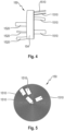
- Fig. 4 shows the wound electrode-separator composite 150, the outside of which is covered with an adhesive tape 154.
- the first sections of the arrester strips 1510 and 1520 protrude from the opposite end faces of the coil-shaped electrode-separator composite 150.
- the protruding first sections of the arrester strips 1510, 1520 can each be shortened slightly so that they do not overlap in the angled state, in which they lie flat on the respective winding end faces.
- Fig. 5 shows a top view of a winding end face, in which the first sections of the arrester strips 1510 lie flat on the winding end face.
- the position and length of the first sections of the arrester strips 1510 are selected so that the angled sections do not overlap.
- the electrode-separator composite 150 can be introduced into the housing parts for further assembly of the energy storage cell.
- the angled sections of the arrester strips 1510 can be fixed to the end face of the winding with an insulating tape.
- any insulation tape sections that lie between the sections of the arrester strips 1510 on the front side and the front side and prevent direct electrical contact with the winding front side.
Landscapes
- Chemical & Material Sciences (AREA)
- Chemical Kinetics & Catalysis (AREA)
- Electrochemistry (AREA)
- General Chemical & Material Sciences (AREA)
- Engineering & Computer Science (AREA)
- Manufacturing & Machinery (AREA)
- Secondary Cells (AREA)
- Connection Of Batteries Or Terminals (AREA)
Priority Applications (2)
| Application Number | Priority Date | Filing Date | Title |
|---|---|---|---|
| EP22192220.6A EP4329083A1 (fr) | 2022-08-25 | 2022-08-25 | Élément électrochimique accumulateur d'énergie et procédé de fabrication |
| PCT/EP2023/072260 WO2024041912A1 (fr) | 2022-08-25 | 2023-08-10 | Cellule de stockage électrochimique d'énergie et son procédé de production |
Applications Claiming Priority (1)
| Application Number | Priority Date | Filing Date | Title |
|---|---|---|---|
| EP22192220.6A EP4329083A1 (fr) | 2022-08-25 | 2022-08-25 | Élément électrochimique accumulateur d'énergie et procédé de fabrication |
Publications (1)
| Publication Number | Publication Date |
|---|---|
| EP4329083A1 true EP4329083A1 (fr) | 2024-02-28 |
Family
ID=83081411
Family Applications (1)
| Application Number | Title | Priority Date | Filing Date |
|---|---|---|---|
| EP22192220.6A Pending EP4329083A1 (fr) | 2022-08-25 | 2022-08-25 | Élément électrochimique accumulateur d'énergie et procédé de fabrication |
Country Status (2)
| Country | Link |
|---|---|
| EP (1) | EP4329083A1 (fr) |
| WO (1) | WO2024041912A1 (fr) |
Citations (6)
| Publication number | Priority date | Publication date | Assignee | Title |
|---|---|---|---|---|
| US20010023038A1 (en) * | 2000-03-16 | 2001-09-20 | Dominique Ligeois | Method of connecting plates of an electrode to a terminal of a storage cell, and the resulting cell |
| DE102009017514A1 (de) | 2009-04-04 | 2010-10-07 | Varta Microbattery Gmbh | Knopfzelle ohne Bördelung |
| WO2010146154A2 (fr) | 2009-06-18 | 2010-12-23 | Varta Microbattery Gmbh | Pile bouton à électrode enroulée et son procédé de fabrication |
| EP3611781A1 (fr) * | 2017-04-14 | 2020-02-19 | LG Chem, Ltd. | Batterie secondaire et procédé de fabrication de batterie secondaire |
| WO2020256023A1 (fr) * | 2019-06-18 | 2020-12-24 | 株式会社村田製作所 | Batterie secondaire |
| CN215815984U (zh) * | 2021-08-23 | 2022-02-11 | 珠海冠宇电池股份有限公司 | 一种电池及电子产品 |
Family Cites Families (1)
| Publication number | Priority date | Publication date | Assignee | Title |
|---|---|---|---|---|
| JP4359100B2 (ja) * | 2003-08-04 | 2009-11-04 | 三洋電機株式会社 | 円筒型アルカリ蓄電池 |
-
2022
- 2022-08-25 EP EP22192220.6A patent/EP4329083A1/fr active Pending
-
2023
- 2023-08-10 WO PCT/EP2023/072260 patent/WO2024041912A1/fr unknown
Patent Citations (6)
| Publication number | Priority date | Publication date | Assignee | Title |
|---|---|---|---|---|
| US20010023038A1 (en) * | 2000-03-16 | 2001-09-20 | Dominique Ligeois | Method of connecting plates of an electrode to a terminal of a storage cell, and the resulting cell |
| DE102009017514A1 (de) | 2009-04-04 | 2010-10-07 | Varta Microbattery Gmbh | Knopfzelle ohne Bördelung |
| WO2010146154A2 (fr) | 2009-06-18 | 2010-12-23 | Varta Microbattery Gmbh | Pile bouton à électrode enroulée et son procédé de fabrication |
| EP3611781A1 (fr) * | 2017-04-14 | 2020-02-19 | LG Chem, Ltd. | Batterie secondaire et procédé de fabrication de batterie secondaire |
| WO2020256023A1 (fr) * | 2019-06-18 | 2020-12-24 | 株式会社村田製作所 | Batterie secondaire |
| CN215815984U (zh) * | 2021-08-23 | 2022-02-11 | 珠海冠宇电池股份有限公司 | 一种电池及电子产品 |
Also Published As
| Publication number | Publication date |
|---|---|
| WO2024041912A1 (fr) | 2024-02-29 |
Similar Documents
| Publication | Publication Date | Title |
|---|---|---|
| EP2443691B1 (fr) | Pile bouton à électrode enroulée et son procédé de fabrication | |
| EP2394324B1 (fr) | Piles-boutons et leur procédé de fabrication | |
| EP3041062A1 (fr) | Cellule électrochimique | |
| EP3916877A1 (fr) | Élément d'accumulateur d'énergie et procédé de fabrication | |
| EP3491682B1 (fr) | Cellule electrochimique et dispositif comprenant ladite cellule | |
| DE202017006038U1 (de) | Knopfzelle mit Wickel-Verbundkörper | |
| WO2022034156A1 (fr) | Cellule de stockage d'énergie et procédé de production | |
| EP3745490B1 (fr) | Procédé de fabrication d'une batterie et batterie fabriquée selon ledit procédé | |
| EP3916868A1 (fr) | Élément d'accumulateur d'énergie et procédé de fabrication | |
| EP3284119B1 (fr) | Batterie comprenant un boîtier métallique prismatique | |
| EP4329083A1 (fr) | Élément électrochimique accumulateur d'énergie et procédé de fabrication | |
| EP4143903A1 (fr) | Pile électrochimique au lithium-ion secondaire | |
| EP4164048A1 (fr) | Élément d'accumulateur d'énergie et procédé de fabrication | |
| WO2024046982A1 (fr) | Cellule de stockage d'énergie et procédé de fabrication d'une cellule de stockage d'énergie de ce type | |
| EP4187688A1 (fr) | Cellule d'accumulateur d'énergie, composite de cellules d'accumulateur d'énergie et procédé de fabrication | |
| EP4266438A1 (fr) | Élément d'accumulateur d'énergie et procédé de fabrication | |
| WO2023194591A1 (fr) | Cellule de stockage d'énergie comprenant un boîtier cylindrique et procédé de fabrication | |
| DE102022113906A1 (de) | Energiespeicherzelle mit zylindrischem Gehäuse und Verfahren zur Herstellung | |
| EP4258397A1 (fr) | Élément d'accumulation d'énergie pourvu de boîtier cylindrique et procédé de fabrication | |
| EP4135088A1 (fr) | Élément accumulateur d'énergie, composite constitué d'éléments accumulateurs d'énergie et procédé de fabrication | |
| EP4152434A1 (fr) | Élément accumulateur d'énergie | |
| WO2023057113A1 (fr) | Élément de stockage d'énergie et procédé de production | |
| EP3806217A1 (fr) | Élément d'accumulateur d'énergie et procédé de fabrication | |
| EP4270614A1 (fr) | Élément d'accumulateur d'énergie | |
| DE202015004285U1 (de) | Knopfzelle |
Legal Events
| Date | Code | Title | Description |
|---|---|---|---|
| PUAI | Public reference made under article 153(3) epc to a published international application that has entered the european phase |
Free format text: ORIGINAL CODE: 0009012 |
|
| STAA | Information on the status of an ep patent application or granted ep patent |
Free format text: STATUS: THE APPLICATION HAS BEEN PUBLISHED |
|
| AK | Designated contracting states |
Kind code of ref document: A1 Designated state(s): AL AT BE BG CH CY CZ DE DK EE ES FI FR GB GR HR HU IE IS IT LI LT LU LV MC MK MT NL NO PL PT RO RS SE SI SK SM TR |