EP4328887A1 - Moving body, waste collection system, and control device - Google Patents
Moving body, waste collection system, and control device Download PDFInfo
- Publication number
- EP4328887A1 EP4328887A1 EP22791395.1A EP22791395A EP4328887A1 EP 4328887 A1 EP4328887 A1 EP 4328887A1 EP 22791395 A EP22791395 A EP 22791395A EP 4328887 A1 EP4328887 A1 EP 4328887A1
- Authority
- EP
- European Patent Office
- Prior art keywords
- waste
- moving body
- path
- path information
- box
- Prior art date
- Legal status (The legal status is an assumption and is not a legal conclusion. Google has not performed a legal analysis and makes no representation as to the accuracy of the status listed.)
- Pending
Links
Images







Classifications
-
- G—PHYSICS
- G05—CONTROLLING; REGULATING
- G05D—SYSTEMS FOR CONTROLLING OR REGULATING NON-ELECTRIC VARIABLES
- G05D1/00—Control of position, course, altitude or attitude of land, water, air or space vehicles, e.g. using automatic pilots
- G05D1/60—Intended control result
- G05D1/69—Coordinated control of the position or course of two or more vehicles
- G05D1/698—Control allocation
- G05D1/6987—Control allocation by centralised control off-board any of the vehicles
-
- B—PERFORMING OPERATIONS; TRANSPORTING
- B65—CONVEYING; PACKING; STORING; HANDLING THIN OR FILAMENTARY MATERIAL
- B65F—GATHERING OR REMOVAL OF DOMESTIC OR LIKE REFUSE
- B65F1/00—Refuse receptacles; Accessories therefor
- B65F1/14—Other constructional features; Accessories
- B65F1/1484—Other constructional features; Accessories relating to the adaptation of receptacles to carry identification means
-
- B—PERFORMING OPERATIONS; TRANSPORTING
- B65—CONVEYING; PACKING; STORING; HANDLING THIN OR FILAMENTARY MATERIAL
- B65F—GATHERING OR REMOVAL OF DOMESTIC OR LIKE REFUSE
- B65F1/00—Refuse receptacles; Accessories therefor
- B65F1/0033—Refuse receptacles; Accessories therefor specially adapted for segregated refuse collecting, e.g. receptacles with several compartments; Combination of receptacles
- B65F1/004—Refuse receptacles; Accessories therefor specially adapted for segregated refuse collecting, e.g. receptacles with several compartments; Combination of receptacles the receptacles being divided in compartments by partitions
-
- B—PERFORMING OPERATIONS; TRANSPORTING
- B65—CONVEYING; PACKING; STORING; HANDLING THIN OR FILAMENTARY MATERIAL
- B65F—GATHERING OR REMOVAL OF DOMESTIC OR LIKE REFUSE
- B65F1/00—Refuse receptacles; Accessories therefor
- B65F1/0033—Refuse receptacles; Accessories therefor specially adapted for segregated refuse collecting, e.g. receptacles with several compartments; Combination of receptacles
- B65F1/004—Refuse receptacles; Accessories therefor specially adapted for segregated refuse collecting, e.g. receptacles with several compartments; Combination of receptacles the receptacles being divided in compartments by partitions
- B65F1/0046—Refuse receptacles; Accessories therefor specially adapted for segregated refuse collecting, e.g. receptacles with several compartments; Combination of receptacles the receptacles being divided in compartments by partitions the partitions being movable, e.g. for varying the volume of the compartments
-
- B—PERFORMING OPERATIONS; TRANSPORTING
- B65—CONVEYING; PACKING; STORING; HANDLING THIN OR FILAMENTARY MATERIAL
- B65F—GATHERING OR REMOVAL OF DOMESTIC OR LIKE REFUSE
- B65F1/00—Refuse receptacles; Accessories therefor
- B65F1/14—Other constructional features; Accessories
- B65F1/1468—Means for facilitating the transport of the receptacle, e.g. wheels, rolls
- B65F1/1473—Receptacles having wheels
-
- G—PHYSICS
- G01—MEASURING; TESTING
- G01C—MEASURING DISTANCES, LEVELS OR BEARINGS; SURVEYING; NAVIGATION; GYROSCOPIC INSTRUMENTS; PHOTOGRAMMETRY OR VIDEOGRAMMETRY
- G01C21/00—Navigation; Navigational instruments not provided for in groups G01C1/00 - G01C19/00
- G01C21/26—Navigation; Navigational instruments not provided for in groups G01C1/00 - G01C19/00 specially adapted for navigation in a road network
- G01C21/34—Route searching; Route guidance
-
- G—PHYSICS
- G05—CONTROLLING; REGULATING
- G05D—SYSTEMS FOR CONTROLLING OR REGULATING NON-ELECTRIC VARIABLES
- G05D1/00—Control of position, course, altitude or attitude of land, water, air or space vehicles, e.g. using automatic pilots
- G05D1/20—Control system inputs
- G05D1/22—Command input arrangements
- G05D1/228—Command input arrangements located on-board unmanned vehicles
- G05D1/2285—Command input arrangements located on-board unmanned vehicles using voice or gesture commands
-
- G—PHYSICS
- G05—CONTROLLING; REGULATING
- G05D—SYSTEMS FOR CONTROLLING OR REGULATING NON-ELECTRIC VARIABLES
- G05D1/00—Control of position, course, altitude or attitude of land, water, air or space vehicles, e.g. using automatic pilots
- G05D1/60—Intended control result
- G05D1/617—Safety or protection, e.g. defining protection zones around obstacles or avoiding hazards
- G05D1/639—Resolving or avoiding being stuck or obstructed
-
- G—PHYSICS
- G06—COMPUTING OR CALCULATING; COUNTING
- G06Q—INFORMATION AND COMMUNICATION TECHNOLOGY [ICT] SPECIALLY ADAPTED FOR ADMINISTRATIVE, COMMERCIAL, FINANCIAL, MANAGERIAL OR SUPERVISORY PURPOSES; SYSTEMS OR METHODS SPECIALLY ADAPTED FOR ADMINISTRATIVE, COMMERCIAL, FINANCIAL, MANAGERIAL OR SUPERVISORY PURPOSES, NOT OTHERWISE PROVIDED FOR
- G06Q10/00—Administration; Management
- G06Q10/04—Forecasting or optimisation specially adapted for administrative or management purposes, e.g. linear programming or "cutting stock problem"
- G06Q10/047—Optimisation of routes or paths, e.g. travelling salesman problem
-
- G—PHYSICS
- G06—COMPUTING OR CALCULATING; COUNTING
- G06Q—INFORMATION AND COMMUNICATION TECHNOLOGY [ICT] SPECIALLY ADAPTED FOR ADMINISTRATIVE, COMMERCIAL, FINANCIAL, MANAGERIAL OR SUPERVISORY PURPOSES; SYSTEMS OR METHODS SPECIALLY ADAPTED FOR ADMINISTRATIVE, COMMERCIAL, FINANCIAL, MANAGERIAL OR SUPERVISORY PURPOSES, NOT OTHERWISE PROVIDED FOR
- G06Q10/00—Administration; Management
- G06Q10/06—Resources, workflows, human or project management; Enterprise or organisation planning; Enterprise or organisation modelling
- G06Q10/063—Operations research, analysis or management
-
- G—PHYSICS
- G06—COMPUTING OR CALCULATING; COUNTING
- G06Q—INFORMATION AND COMMUNICATION TECHNOLOGY [ICT] SPECIALLY ADAPTED FOR ADMINISTRATIVE, COMMERCIAL, FINANCIAL, MANAGERIAL OR SUPERVISORY PURPOSES; SYSTEMS OR METHODS SPECIALLY ADAPTED FOR ADMINISTRATIVE, COMMERCIAL, FINANCIAL, MANAGERIAL OR SUPERVISORY PURPOSES, NOT OTHERWISE PROVIDED FOR
- G06Q10/00—Administration; Management
- G06Q10/30—Administration of product recycling or disposal
-
- G—PHYSICS
- G06—COMPUTING OR CALCULATING; COUNTING
- G06Q—INFORMATION AND COMMUNICATION TECHNOLOGY [ICT] SPECIALLY ADAPTED FOR ADMINISTRATIVE, COMMERCIAL, FINANCIAL, MANAGERIAL OR SUPERVISORY PURPOSES; SYSTEMS OR METHODS SPECIALLY ADAPTED FOR ADMINISTRATIVE, COMMERCIAL, FINANCIAL, MANAGERIAL OR SUPERVISORY PURPOSES, NOT OTHERWISE PROVIDED FOR
- G06Q30/00—Commerce
- G06Q30/02—Marketing; Price estimation or determination; Fundraising
- G06Q30/0241—Advertisements
- G06Q30/0251—Targeted advertisements
- G06Q30/0265—Vehicular advertisement
-
- G—PHYSICS
- G08—SIGNALLING
- G08G—TRAFFIC CONTROL SYSTEMS
- G08G1/00—Traffic control systems for road vehicles
- G08G1/20—Monitoring the location of vehicles belonging to a group, e.g. fleet of vehicles, countable or determined number of vehicles
- G08G1/202—Dispatching vehicles on the basis of a location, e.g. taxi dispatching
-
- G—PHYSICS
- G16—INFORMATION AND COMMUNICATION TECHNOLOGY [ICT] SPECIALLY ADAPTED FOR SPECIFIC APPLICATION FIELDS
- G16Y—INFORMATION AND COMMUNICATION TECHNOLOGY SPECIALLY ADAPTED FOR THE INTERNET OF THINGS [IoT]
- G16Y10/00—Economic sectors
- G16Y10/40—Transportation
-
- G—PHYSICS
- G16—INFORMATION AND COMMUNICATION TECHNOLOGY [ICT] SPECIALLY ADAPTED FOR SPECIFIC APPLICATION FIELDS
- G16Y—INFORMATION AND COMMUNICATION TECHNOLOGY SPECIALLY ADAPTED FOR THE INTERNET OF THINGS [IoT]
- G16Y40/00—IoT characterised by the purpose of the information processing
- G16Y40/60—Positioning; Navigation
-
- B—PERFORMING OPERATIONS; TRANSPORTING
- B65—CONVEYING; PACKING; STORING; HANDLING THIN OR FILAMENTARY MATERIAL
- B65F—GATHERING OR REMOVAL OF DOMESTIC OR LIKE REFUSE
- B65F2210/00—Equipment of refuse receptacles
- B65F2210/112—Coding means to aid in recycling
- B65F2210/1126—Symbols
-
- B—PERFORMING OPERATIONS; TRANSPORTING
- B65—CONVEYING; PACKING; STORING; HANDLING THIN OR FILAMENTARY MATERIAL
- B65F—GATHERING OR REMOVAL OF DOMESTIC OR LIKE REFUSE
- B65F2210/00—Equipment of refuse receptacles
- B65F2210/128—Data transmitting means
-
- B—PERFORMING OPERATIONS; TRANSPORTING
- B65—CONVEYING; PACKING; STORING; HANDLING THIN OR FILAMENTARY MATERIAL
- B65F—GATHERING OR REMOVAL OF DOMESTIC OR LIKE REFUSE
- B65F2210/00—Equipment of refuse receptacles
- B65F2210/165—Remote controls
-
- B—PERFORMING OPERATIONS; TRANSPORTING
- B65—CONVEYING; PACKING; STORING; HANDLING THIN OR FILAMENTARY MATERIAL
- B65F—GATHERING OR REMOVAL OF DOMESTIC OR LIKE REFUSE
- B65F2210/00—Equipment of refuse receptacles
- B65F2210/168—Sensing means
-
- B—PERFORMING OPERATIONS; TRANSPORTING
- B65—CONVEYING; PACKING; STORING; HANDLING THIN OR FILAMENTARY MATERIAL
- B65F—GATHERING OR REMOVAL OF DOMESTIC OR LIKE REFUSE
- B65F2210/00—Equipment of refuse receptacles
- B65F2210/184—Weighing means
-
- G—PHYSICS
- G01—MEASURING; TESTING
- G01C—MEASURING DISTANCES, LEVELS OR BEARINGS; SURVEYING; NAVIGATION; GYROSCOPIC INSTRUMENTS; PHOTOGRAMMETRY OR VIDEOGRAMMETRY
- G01C21/00—Navigation; Navigational instruments not provided for in groups G01C1/00 - G01C19/00
- G01C21/20—Instruments for performing navigational calculations
-
- G—PHYSICS
- G05—CONTROLLING; REGULATING
- G05D—SYSTEMS FOR CONTROLLING OR REGULATING NON-ELECTRIC VARIABLES
- G05D2105/00—Specific applications of the controlled vehicles
- G05D2105/14—Specific applications of the controlled vehicles for collecting waste or trash
-
- G—PHYSICS
- G05—CONTROLLING; REGULATING
- G05D—SYSTEMS FOR CONTROLLING OR REGULATING NON-ELECTRIC VARIABLES
- G05D2107/00—Specific environments of the controlled vehicles
- G05D2107/87—Recreational areas, e.g. amusement parks
-
- G—PHYSICS
- G05—CONTROLLING; REGULATING
- G05D—SYSTEMS FOR CONTROLLING OR REGULATING NON-ELECTRIC VARIABLES
- G05D2109/00—Types of controlled vehicles
- G05D2109/10—Land vehicles
Definitions
- the present disclosure relates to a movable waste box as an autonomously-movable moving body, a waste collection system including the movable waste box, and a supervision apparatus which controls the movable waste box.
- a waste collection management system including an acquiring unit which acquires request information regarding a waste collection request from a user, a determining unit which determines the presence or absence of an addressing moving body which can address the request information, a generating unit which generates a dispatch instruction for dispatching the addressing moving body to a collection point based on the request information when the addressing moving body is present, and a guiding unit which guides the addressing moving body to the collection point based on the dispatch instruction and causes the addressing moving body to perform collection of target waste as a target for a collection request.
- the addressing moving body is a waste collection vehicle and automatic driving vehicle (for example, Patent Literature 1).
- Patent Literature 1 JP 2020-87134
- An object of the present disclosure is to save the trouble of having to call a collection moving body for collecting waste and then wait for arrival of the collection moving body.
- the present disclosure relates to a moving body to collect waste.
- the moving body according to the present disclosure includes:
- a "unit” may be read as a “circuit”, “step”, “procedure”, “process”, or “circuitry” as appropriate.
- a waste collection system 1000 of Embodiment 1 is described with reference to Fig. 1 to Fig. 8 .
- Fig. 1 illustrates the system configuration of the waste collection system 1000.
- Fig. 2 illustrates an external appearance of a movable waste box 100 included in the waste collection system 1000.
- Fig. 3 illustrates a tourist site 400 where the movable waste box 100 is used.
- the waste collection system 1000 includes a plurality of movable waste boxes 100 and a supervision apparatus 200.
- Each movable waste box 100 and the supervision apparatus 200 communicate via a network 330.
- the movable waste box 100 receives path information 201a transmitted from a path information generating unit 201 of the supervision apparatus 200, and autonomously moves by following the path information 201a.
- the path information generating unit 201 transmits the path information 201a via a communication interface 960B, which will be described below.
- the movable waste box 100 is referred to as an AMR (autonomous mobile robot).
- the movable waste box 100 is used on a site such as a tourist site or theme park. In the following description, the movable waste box 100 is described when used on the tourist site 400, by way of example.
- the movable waste box 100 makes the rounds of the tourist site 400.
- the movable waste box 100 includes a waste box 120.
- the movable waste box 100 moves with four tires 101. Note in Fig. 2 that the right rear tire 101 is not viewed.
- the movable waste box 100 includes, in addition to the waste box 120, various sensors for autonomous movement such as a GNSS antenna 605, cameras 181, a sonar 182, a millimeter wave radar 183, and a LiDAR 184, and these sensors will be described further below.
- the waste box 120 is formed of a separate waste box 121, a separate waste box 122, and a separate waste box 123. A different waste box has an opening formed, and waste can be put from the opening.
- a waste type of the separate waste box is displayed, such as burnable waste 124a, plastic waste 124b, drinking cup waste 124c.
- the display of burnable waste 124a corresponds to the separate waste box 121
- the display of plastic waste 124b corresponds to the separate waste box 122
- the display of drinking cup waste 124c corresponds to the separate waste box 123.
- a plurality of tourists are walking on a certain tourist site where a plurality of shops 320 are present.
- the movable waste box 100 travels around the tourist site 400 at a speed on the order of 1 km per hour or 2 km per hour.
- the movable waste box 100 makes the rounds of the tourist site 400 by following a path indicated by the path information 201a.
- a street camera 310 is installed in the vicinity of each shop 320. Images taken by the street cameras 310 can be used for processing such as generation of human stream information 13 and waste extraction, which will be described further below.
- Fig. 4 illustrates a specific configuration of the waste collection system 1000.
- the movable waste box 100 includes a control device 110, the waste box 120, and the sensor group including the cameras 181.
- the movable waste box 100 receives a positioning signal from a GNSS satellite 40 to measure a position, and performs self position estimation by using the positioning result and the measurement result of the sensor group.
- the supervision apparatus 200 communicates with the movable waste box 100 via the network 330.
- the control device 110 transmits waste collection information 100b indicating a situation of waste collection to the supervision apparatus 200 via the network 330.
- the supervision apparatus 200 transmits the path information 201a to the movable waste box 100.
- the path information generating unit 201 of the supervision apparatus 200 acquires, from outside the supervision apparatus 200, information about human streams, shop information, dynamic map information, and information about facilities.
- the movable waste box 100 and the supervision apparatus 200 are specifically described below.
- Fig. 5 illustrates each device mounted on the movable waste box 100.
- the movable waste box 100 includes the control device 110, an autonomous movement device 170, and a unified sensor unit 180.
- the unified sensor unit 180 includes the GNSS antenna 605, the cameras 181, the sonar 182, the millimeter wave radar 183, the LiDAR 184, a GNSS positioning device 185, and a sensor fusion unit 186.
- the unified sensor unit 180 is a unit which measures data for the movable waste box 100 to autonomously move. As illustrated in Fig. 4 , the cameras 181 are installed on a front side and a rear side. Those from the cameras 181 to the LiDAR 184 may be represented as a sensor group.
- the GNSS antenna 605 is connected to the GNSS positioning device 185 to configure a locator (position assessment device). Measurement data of the sensor group and the positioning result of the GNSS positioning device 185 are inputted to the sensor fusion unit 186.
- the sensor fusion unit 186 inputs unified information 188 acquired by unifying the inputted data to a movement control unit 111.
- the control device 110 is a device which controls autonomous movements of the movable waste boxes 100 and also supports waste collection to the waste boxes 120.
- the control device 110 includes the movement control unit 111, a storage device 112, a waste extracting unit 113, and a waste amount control unit 114.
- the movement control unit 111 has unified information 188 inputted from the unified sensor unit 180. Based on the unified information 188, the path information 201a held in the storage device 112, and an instruction from the supervision apparatus 200, the movement control unit 111 generates autonomous movement control information 111a for the autonomous movement device 170 to cause any movable waste box 100 to autonomously move.
- the waste extracting unit 113 extracts waste by using the sensor group. Waste extraction will be described further below.
- the waste amount control unit 114 monitors the accommodation capacity of waste of the separate waste box 121, the separate waste box 122, and the separate waste box 123.
- the storage device 112 has stored therein a high-precision map received from the supervision apparatus 200 and point-group data measured by the LiDAR 184, and has them held in a high-precision map and point-group database (high-precision map/point-group DB) 119. Also, the storage device 112 has stored therein learned model 113a and the path information 201a received from the supervision apparatus 200.
- the storage device 112 is implemented by an auxiliary storage device 930A.
- the autonomous movement device 170 causes any movable waste box 100 to autonomously move based on the autonomous movement control information 111a. Specifically, the autonomous movement device 170 causes the movable waste box 100 to autonomously move by controlling a traveling mechanism included in the movable waste box 100, such as a motor or steering mechanism not illustrated in the drawings. Note that each movable waste box 100 has a battery as a motive power source and each movable waste box 100 is so called an electric automobile.
- Fig. 6 illustrates the hardware configuration of the control device 110.
- the control device 110 is a computer.
- the control device 110 includes a processor 910A.
- the control device 110 includes, in addition to the processor 910A, other hardware including a main storage device 920A, the auxiliary storage device 930A, an input interface 940A, an output interface 950A, and a communication interface 960A.
- the processor 910A is connected to the other hardware via a signal line 970A to control the other hardware.
- the control device 110 includes the movement control unit 111, the waste extracting unit 113, and the waste amount control unit 114 as functional components.
- the functions of the movement control unit 111, the waste extracting unit 113, and the waste amount control unit 114 are implemented by a control program 110a.
- the processor 910A is a device which executes the control program 110a.
- the control program 110a is a program which implements the functions of the movement control unit 111, the waste extracting unit 113, and the waste amount control unit 114.
- the processor 910A is an IC (Integrated Circuit) which performs arithmetic process. Specific examples of the processor 910A are a CPU (Central Processing Unit), a DSP (Digital Signal Processor), and a GPU (Graphics Processing Unit).
- main storage device 920A Specific examples of the main storage device 920A are an SRAM (Static Random Access Memory) and a DRAM (Dynamic Random Access Memory).
- SRAM Static Random Access Memory
- DRAM Dynamic Random Access Memory
- the main storage device 920A retains arithmetic operation results of the processor 910A.
- the auxiliary storage device 930A is a non-volatile storage device which retains data.
- a specific example of the auxiliary storage device 930A is an HDD (Hard Disk Drive).
- the auxiliary storage device 930A may be a portable recording medium such as an SD (registered trademark) (Secure Digital) memory card, NAND flash, flexible disk, optical disk, compact disk, Blu-ray (registered trademark) disk, or DVD (Digital Versatile Disk).
- SD registered trademark
- NAND flash non-volatile storage device
- NAND flash non-volatile storage device
- flexible disk such as an SD (registered trademark) (Secure Digital) memory card, NAND flash, flexible disk, optical disk, compact disk, Blu-ray (registered trademark) disk, or DVD (Digital Versatile Disk).
- the auxiliary storage device 930A has stored therein the high-precision map and point-group database 119, the learned model 113a, the path information 201a, and the control program 110
- the input interface 940A is a port to which data is inputted from each device.
- the output interface 950A is a port to which various devices are connected and through which data is caused by the processor 910A to be outputted to various devices.
- the autonomous movement device 170 is connected.
- the communication interface 960A is a communication port for the processor to communicate with another device.
- a communication device 190 is connected to the communication interface 960A.
- the control device 110 communicates with the supervision apparatus 200. Specifically, with the communication device 190 communicating with a communication device 210, which will be described further below, included in the supervision apparatus 200, communication between the control device 110 and the supervision apparatus 200 is established.
- the control device 110 may include a plurality of processors which replace the processor 910A.
- the plurality of these processors share execution of the control program 110a.
- each processor is a device which executes the control program 1 10a.
- Data, information, signal values, and variable values to be used, processed, or outputted by the control program 110a are stored in the main storage device 920A, the auxiliary storage device 930A, or a register or cache memory in the processor 910A.
- the control program 110a is a program which causes a computer to perform each process, each procedure, or each step acquired by reading the "unit" of each of the movement control unit 111, the waste extracting unit 113, and the waste amount control unit 114 as a "process", "procedure”, or "step”.
- a control method is a method to be performed by the control device 110 as a computer executing the control program 110a.
- the control program 110a may be provided as being held in a computer-readable recording medium or may be provided as a program product.
- Fig. 7 illustrates the hardware configuration of the supervision apparatus 200.
- the supervision apparatus 200 is a computer having a configuration similar to that of the control device 110.
- the supervision apparatus 200 includes a processor 910B and so forth as hardware. Since the configuration of the supervision apparatus 200 of Fig. 7 is similar to that of the control device 110 of Fig. 6 , as for reference characters of the processor and so forth, B is provided instead of A in Fig. 6 . Only portions different from the control device 110 of Fig. 6 are described.
- the supervision apparatus 200 includes the path information generating unit 201 and a moving body monitoring unit 202 as functional components.
- the functions of the path information generating unit 201 and the moving body monitoring unit 202 are implemented by a supervision program 200a.
- the supervision program 200a is executed by the processor 910B.
- An auxiliary storage device 930B has stored therein the supervision program 200a.
- the supervision program 200a is a program which causes a computer to perform each process, each procedure, or each step acquired by reading the "unit" of each of the path information generating unit 201 and the moving body monitoring unit 202 as a "process", "procedure", or "step".
- an infection method is a method to be performed by the supervision apparatus 200 as a computer executing the supervision program 200a.
- the supervision program 200a may be provided as being held in a computer-readable recording medium or may be provided as a program product.
- the communication device 210 is connected to the communication interface 960B.
- the supervision apparatus 200 communicates with the control device 110 via the communication device 210.
- the communication device 210 is illustrated also in Fig. 2 .
- the movable waste box 100 illustrated in Fig. 2 is a moving body which collects waste.
- the movement control unit 111 included in the control device 110 causes the movable waste box 100 to autonomously move by following the path information 201a indicating a path.
- the movable waste box 100 autonomously travels at a speed equal to or slow than 6 km per hour.
- the movable waste box 100 travels at a speed between 1 km per hour and 2 km per hour.
- the speed of autonomous traveling is simply an example.
- the speed of the movable waste box 100 by autonomous traveling is not limited.
- the waste box 120 is a waste box which accepts waste a person who is present, partway on a path, on the path or along the path has.
- the movable waste box 100 travels at a low speed between 1 km per hour and 2 km per hour, and collects waste partway on a traveling path.
- Fig. 8 illustrates a path on the tourist site 400 of which the movable waste box 100 makes the rounds.
- the plurality of shops 320 are present.
- the plurality of shops 320 are classified into five shops from a shop 320a to a shop 320e.
- the movable waste box 100 follows the path information 201a to make the rounds of a path 401 specified by points P1, P2, P3, P4, and P1 in a forwarding direction 100a.
- the movable waste box 100 makes the rounds of a path 402 specified by points P6, P2, P3, P6, and P6.
- the movable waste box 100 has path information 201b corresponding to the path 402, and can make the rounds of the path 402 by switching the path information 201a to the path information 201b.
- the movable waste box 100 has a human sensor which detects a movement of a person.
- the sensor group the unified sensor unit 180 has can be used.
- the movement control unit 111 causes the speed of the movable waste box 100 to be decreased. That is, as illustrated in Fig. 3 , when the sensor group of the unified sensor unit 180 detects a tourist 410a approaching the movable waste box 100, the movement control unit 111 transmits, to the autonomous movement device 170, autonomous movement control information 111a including a speed reduction instruction.
- a speed control unit 171 follows the speed reduction instruction to decrease the speed of the movable waste box 100. For example, when the movable waste box 100 is traveling at 1 to 2 km/h per hour at normal times, the speed is decreased so that the movable waste box 100 is caused to travel at 0 to 1 km/h per hour at normal times.
- the speed reduction instruction may be a stop instruction.
- the speed control unit 171 stops the movement of the movable waste box 100.
- the movement control unit 111 causes the speed of the movable waste box 100 to be increased.
- the movement control unit 111 transmits, to the autonomous movement device 170, autonomous movement control information 111a including a speed increase instruction.
- the speed control unit 171 follows the speed increase instruction to increase the speed of the movable waste box 100. For example, when the movable waste box 100 is traveling at 0 to 1 km/h per hour at normal times, the speed is decreased so that the movable waste box 100 is caused to travel at 1 to 2 km/h per hour at normal times.
- the movable waste box 100 changes its speed with a person approaching or going away, there is an effect that the tourists 410 can easily throw waste away.
- the control device 110 has a plurality of pieces of path information stored in the storage device 112.
- the auxiliary storage device 930A as the storage device 112 has held therein two path information, the path information 201a and the path information 201b.
- the movement control unit 111 selects path information from among the plurality of pieces of path information.
- the accommodation capacity of waste can be detected by an accommodation capacity sensor arranged in the waste box 120.
- the accommodation capacity sensor can be replaced by a weight sensor, which will be described further below.
- the accommodation capacity sensor is arranged in each of the separate waste box 121, the separate waste box 122, and the separate waste box 123.
- the movement control unit 111 selects the path information 201b, and makes the rounds of the path 402 ( Fig. 8 ) by following the path information 201b.
- the path information 201b is associated with attribute information indicating that the amount of emission of burnable waste is small.
- the threshold value of burnable waste is determined with a margin of waste accommodation, and waste can be collected to some extent even if burnable waste is emitted on the path 402. Process when the waste box is filled with burnable waste will be described further below. In this manner, since the movable waste box 100 changes the path depending on the accommodation capacity of waste, the waste box 120 can be effectively used.
- the movable waste box 100 as a moving body includes the cameras 181 as an image-taking device which takes an image of the vicinity.
- the auxiliary storage device 930A of the control device 110 has held therein the learned model 113a.
- the learned model 113a is a model for extracting waste from an image on which waste appears.
- the waste extracting unit 113 of the control device 110 extracts waste by using the learned model 113a from the image taken by any camera 181 and, when waste is extracted, outputs a waste extraction signal.
- the waste extracting unit 113 transmits, as a waste extraction signal, an extraction notification that waste has been extracted to the supervision apparatus 200 which manages the movable waste box 100. Specifically, the waste extracting unit 113 transmits an extraction notification to the supervision apparatus 200 via the communication interface 960A.
- the extraction notification includes a waste extraction time and a waste extraction location.
- a supervision station not illustrated in the drawings, having the supervision apparatus 200 can notify an administrator of the tourist site 400 that waste has been extracted.
- the movable waste box 100 may include an arm mechanism 150 which catches and accommodates waste into the waste box 120. Upon outputting a waste extraction signal, the waste extracting unit 113 may cause waste the image of which has been taken to be accommodated in the waste box 120 by using the arm mechanism 150.
- control device 110 extracts waste by using the learned model 113a, waste can be efficiently collected.
- the learned model 113a is generated by the path information generating unit 201 of the supervision apparatus 200.
- the path information generating unit 201 learns images of waste by, for example, supervised learning, and generates the learned model 113a.
- the generated learned model 113a is held in the auxiliary storage device 930A of the control device 110.
- the learned model 113a may be able to extract a person such as a tourist 410b having waste illustrated in Fig. 3 from any image.
- the waste extracting unit 113 extracts a person having waste from any image taken by any camera 181 as an image-taking device in the vicinity of the path indicated by the path information by using the learned model 113a.
- the movement control unit 111 causes the movable waste box 100 to leave the path and approach the person having waste.
- the movement control unit 111 generates autonomous movement control information 111a indicating that the movable waste box 100 approaches the person having waste for output to the autonomous movement device 170.
- the movement control unit 111 causes the movable waste box 100 to be returned to the original path. Specifically, if collection of waste from the person having waste has been confirmed by the sensor group, the movement control unit 111 generates autonomous movement control information 111a for making an instruction of returning to the original path for output to the autonomous movement device 170.
- the movable waste box 100 approaches the person having waste, the person having waste can easily throw waste away, and beautification of the tourist site 400 is improved.
- the movable waste box 100 includes a waste box monitoring device which monitors the waste box 120.
- the waste box monitoring device can be implemented by the sensor group such as the cameras 181, the sonar 182, the millimeter wave radar 183, and the LiDAR 184.
- a sensor for waste drop detection 187 is arranged on an upper portion of an opening at the center of the waste box 120.
- the sensor 187 is configured of, for example, a camera, an infrared sensor, a sonar, an optical sensor, or the like. This sensor for waste drop detection 187 is arranged also at the same position on the right side.
- the waste extracting unit 113 determines whether there is any waste with its position changed from the inside of the waste box 120 to the outside of the waste box 120.
- the waste extracting unit 113 Upon determining that there is any waste with its position changed from the inside of the waste box 120 to the outside of the waste box 120, the waste extracting unit 113 transmits an alert notification to the supervision apparatus 200 which manages the movable waste box 100.
- the alert notification includes a time and location of detection of the waste drop.
- the supervision station where the supervision apparatus 200 is present notifies the administrator of the tourist site 400 of the details of the alert notification. With this, beautification of the tourist site 400 is improved.
- the movable waste box 100 may include the arm mechanism 150 which catches and accommodates waste into the waste box 120.
- the waste extracting unit 113 identifies, based on the learned model 113a, the waste with its position changed and, by using the arm mechanism 150, causes the waste with its position changed to be collected inside of the waste box 120. With this, beautification of the tourist site 400 is improved.
- the waste extracting unit 113 can detect a waste drop from a weight sensor installed in the waste box 120.
- weight sensors 131, 132, and 133 respectively arranged in the separate waste box 121, the separate waste box 122, and the separate waste box 123 are illustrated.
- the weight sensors 131, 132, and 133 when collectively called are represented as a weight sensor 130.
- the waste extracting unit 113 can detect waste by making a comparison between a high-precision map as a three-dimensional map and information about a point group in real time acquired by the LiDAR 184 (point-group database). This process can be used for any waste dropped on roads in general. By further using the learned model 113a, when an image corresponding to a difference in the point group is present, the waste extracting unit 113 may determine whether data of the point group represents waste.
- the weight sensor 130 which detects the weight of waste for each separate waste box may be arranged inside the device of the movable waste box 100.
- an infrared sensor or the like which detects, for each separate waste box, the height of waste accumulated inside the waste box or the position of waste positioned at the highest may be arranged on a back surface of a ceiling part of the movable waste box 100. If waste of part of separate waste increases based on the detection result of the weight sensor 130, the infrared sensor, or the like, after the capacity of another separate waste box is detected, the capacity of the separate waste box with increased waste is increased. Specifically, the process is as follows. As illustrated in Fig.
- the waste box 120 is divided into the separate waste box 121, the separate waste box 122, and the separate waste box 123 for each type of waste.
- the separate waste box 121, the separate waste box 122, and the separate waste box 123 can have their accommodation capacity of waste changed by control.
- the process is as follows.
- the partition plate driving device 129 receives control, the partition plate driving device 129 can move partition plates 125, 126, 127, and 128 independently to a front-rear direction of the movable waste box 100. With this, the capacities of the separate waste box 121, the separate waste box 122, and the separate waste box 123 can be changed.
- the waste amount control unit 114 of the control device 110 controls the accommodation capacity of waste accommodatable in each separate waste box. With this, use efficiency of the waste box 120 is improved.
- waste collection system 1000 The operation of the waste collection system 1000 is described below, with attention being paid to the supervision apparatus 200.
- the movable waste box 100 illustrated in Fig. 4 autonomously moves at a speed equal to or slower than 6 km per hour by following path information indicating a path.
- the movable waste box 100 includes the waste box 120 which accepts waste a person who is present, partway on a path, on the path or along the path has.
- the supervision apparatus 200 has the path information generating unit 201 which generates path information and transmits the path information to a moving body.
- the path information generating unit 201 generates path information based on streams of people in an area such as the tourist site 400 where the movable waste box 100 is scheduled to move.
- Human stream information 13 indicating streams of people can be acquired from the street camera 310 illustrated in Fig. 3 . Alternatively, it can be acquired from an institution such as a corporation which collects the human stream information 13.
- the path information generating unit 201 generates path information indicating that the rounds are made in a place with many streams of people, thereby allowing waste to be efficiently collected from the tourists 410 on the tourist site 400.
- the path information may include the human stream information 13 indicating a stream of people.
- the path information generating unit 201 may generate path information based on a facility including the shops 320 arranged in an area where the movable waste box 100 is scheduled to move. Specifically, in Fig. 8 , if the shop 320d and the shop 320e are popular shops where people gather, the path information generating unit 201 generates a path including the points P5, P6, P2, and P3. Since more people gather in popular shops, by including the locations of the popular shops in the path, it is possible to efficiently collect waste from the tourists 410.
- the path information can be acquired from a device outside the supervision apparatus 200.
- the auxiliary storage device 930B has stored therein waste emission information indicating waste emission situations at a plurality of locations in the area where the movable waste box 100 is scheduled to move.
- the path information generating unit 201 may generate path information based on the waste emission information stored in the auxiliary storage device 930B. With the path information generating unit 201 referring to the waste emission information and generating path information including locations with large emission amounts of waste, waste can be efficiently collected.
- the waste emission information has recorded thereon, for example, a waste emission amount with respect to time for each location.
- the path information generating unit 201 can acquire the waste emission information from a device outside the supervision apparatus 200.
- the waste emission information includes, as described above, time information indicating a time when waste is emitted. With this, path information effective for waste collection can be generated.
- a learned model for generating path information may be used. Specifically, the process is as follows.
- the path information generating unit 201 learns the locations and times when more waste is emitted to generate a learned model for path information generation.
- the path information generating unit 201 generates path information including a location and time where and when the movable waste box 100 should make the rounds in a prioritized manner.
- the waste collection system 1000 includes the plurality of movable waste boxes 100.
- the path information generating unit 201 generates different path information for each movable waste box 100, thereby covering waste collection on the tourist site 400 as a scheduled area where arrangement of the plurality of movable waste boxes 100 is scheduled. With this, waste on the tourist site 400 can be completely collected.
- the movable waste box 100 transmits an excess signal to the supervision apparatus 200.
- the path information generating unit 201 transmits a movement destination instruction for making an instruction of a movement destination to a transmission moving body, which is the movable waste box 100 transmitting the excess signal, to cause the transmission moving body to move to the movement destination.
- the movement destination is a storage warehouse 340 illustrated in Fig. 8 .
- the path information generating unit 201 transmits path information identical to the path information transmitted to the transmission moving body to the different movable waste box 100. With this, the transmission moving body filled with waste can be changed to the different movable waste box 100.
- the supervision apparatus 200 has the moving body monitoring unit 202 that monitors the movement state of the movable waste box 100 to control the movement state of the movable waste box 100 based on the monitoring result.
- Position information on which monitoring is based is transmitted from the movable waste box 100.
- the position information is associated with a presence time and a presence position. From the position information and the movable waste box 100 the image of which was taken by the street camera 310, the moving body monitoring unit 202 can control the movement state of the movable waste box 100. In this manner, by remotely controlling the movable waste box 100, the tourist site 400 can be efficiently beautified.
- the movable waste box 100 as an automatic traveling vehicle equipped with a waste box itself is caused to travel along the movement path of the tourists 410, and thus it is possible to save the tourists 410 trouble of finding a waste box, and improve beautification of the tourist site 400.
- the waste collection system 1000 of Embodiment 2 is described with reference to Fig. 9 to Fig. 14 . Since the waste collection system 1000 of Embodiment 2 is identical to that of Fig. 1 , description is omitted.
- the waste collection system 1000 includes a human stream information generating unit 203.
- the functions of the human stream information generating unit 203 may be arranged in the supervision apparatus 200 or may be arranged in another device different from the supervision apparatus 200 and outside the supervision apparatus 200. However, the human stream information generating unit 203 is arranged inside the waste collection system 1000. In the following, a configuration is described, by way of example, in which the supervision apparatus 200 includes the human stream information generating unit 203.
- Fig. 9 illustrates the configuration in which the supervision apparatus 200 includes the human stream information generating unit 203.
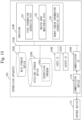
- Fig. 10 illustrates the hardware configuration of the supervision apparatus 200.
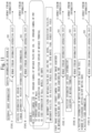
- Fig. 11 illustrates Type A to Type E as generation types of human stream information 13 by the human stream information generating unit 203.
- the human stream information generating unit 203 generates the human stream information 13 based on information such as external input information or sensing information of a sensor X.
- the sensor X will be described further below.
- the human stream information generating unit 203 can generate the human stream information 13 from image information, position information of a person, and speed information of a person acquired by the sensor X mounted on the movable waste box 100 or the sensor X provided outside the movable waste box 100.
- the "sensor X provided outside the movable waste box 100” means the sensor X not mounted on the movable waste box 100.
- the sensor X is described.
- the sensor X is configured of one or plurality of the following (1) to (6):
- the movable terminal is a terminal device.
- the street camera 310 may be arranged at a location such as (1) to (4) below:
- the human stream information generating unit 203 based on first image information acquired by the street camera 310, second image information acquired by the cameras 181 of the movable waste box 100, and third image information acquired by the camera mounted on the PMV, the human stream information generating unit 203 recognizes a person from these images and tracks the person. Then, the human stream information generating unit 203 measures items such as a position, speed, or change in position of the tracked person, or the number of people. By measuring these items, from, for example, "human presence density, human average movement speed, human moving direction, and human moving flux" per cubic meter, for each unit space, the human stream information generating unit 203 can generate the human stream information 13 indicating an evaluation index of the human stream. As an evaluation index of the human stream, that is, the human stream information 13, a value for numerical value evaluation of a "level of a degree of off-peak/congestion and density of the moving flux" can be used.
- the human stream information generating unit 203 can generate the human stream information 13 based on the position information and the speed information acquired by the movable terminal owned by the tourist.
- the human stream information generating unit 203 can measure the number of theme-park users (tourists) at a theme park per unit time and can find the human stream information 13 from the number of people for each moving body or each location.
- Fig. 12 illustrates number lines indicating values V of the human stream information 13.
- a path with a value V equal to or smaller than a threshold value V1 is an undercrowded path with less human streams.
- a path with a value V equal to or larger than a threshold value V2 is an overcrowded path with more human streams.
- a path with a value between the threshold value V1 and the threshold value V2 is an intermediate density path.
- the intermediate density paths include one section with a value V represented by one value between V1 and V2 and a plurality of sections with a value V represented by a plurality of values between V1 and V2. The intermediate density path on an upper side of Fig.
- the path information generating unit 201 schedules pass passage priorities and a passing order.
- the path information generating unit 201 sets priority 4 to the overcrowded path, priority 3 to the intermediate density path with V32, priority 2 to the intermediate density path with V32, and priority 1 to the undercrowded path.
- the path information generating unit 201 refers to the set priorities and sets path information as a passage route of the movable waste box 100 so that the number of passages of the overcrowded path of the movable waste box 100 increases per unit time or per use time of a facility the tourists use or the number of passages of the undercrowded path decreases per unit time or per use time.
- Fig. 13 illustrates an example in which the path information generating unit 201 generates path information formed of, from left, an undercrowded path, an intermediate density path with the value V31, an intermediate density path with the value V32, an overcrowded path, and an intermediate density path with the value V32.
- the order of passage is set.
- S1 to S17 represents the order of passages.
- S1 represents a start, and S17 represents an end.
- the movable waste box 100 passes the overcrowded path six times, passes each intermediate density path with the value V32 four times, passes the intermediate density path with the value V31 twice, and passes the undercrowded path once. With this, the movable waste box 100 can efficiently collect waste in accordance with density.
- the supervision apparatus 200 includes the human stream information generating unit 203 which generates the human stream information 13. And, the path information generating unit 201 generates path information by using the human stream information 13 generated by the human stream information generating unit 203.
- the human stream information is generated inside the waste collection system 1000, and path information is generated from the human stream information generated inside the waste collection system 1000. Therefore, correct human stream information necessary for the waste collection system 1000 can be quickly acquired. Also, since path information is generated from the human stream information that is correct for the waste collection system 1000, efficient waste collection can be made. Also, the degree of satisfaction of tourists on a waste emission side is improved.
- the waste collection system 1000 of Embodiment 3 is described with reference to Fig. 14 to Fig. 16 .
- the system configuration of the waste collection system 1000 of Embodiment 3 is identical to that of Fig. 1 .
- Fig. 14 illustrates the configuration of the supervision apparatus 200.
- Fig. 15 illustrates the hardware configuration of the control device 110.
- Fig. 16 illustrates the hardware configuration of the supervision apparatus 200.
- the movable waste box 100 and the supervision apparatus 200 issue an alert in accordance with the weight of waste or the capacity of waste of the movable waste box 100.
- the movable waste box 100 includes a movement-side alert unit 115 which issues an alert.
- the supervision apparatus 200 includes a supervision-side alert unit 204 which issues an alert.
- weight sensors 151, 152, and 153 are arranged in the separate waste box 121, the separate waste box 122, and the separate waste box 123, respectively.
- accommodation capacity sensors 141, 142, and 143 are arranged in the separate waste box 121, the separate waste box 122, and the separate waste box 123, respectively.
- the weight sensors are represented as a weight sensor 150 unless distinction is required.
- the accommodation capacity sensors are represented as an accommodation capacity sensor 140 unless distinction is required.
- the movement-side alert unit 115 issues an alert based on the detection result of the sensor which detects at least any of the weight or the accommodation capacity of waste accumulated in the waste box.
- the movement-side alert unit 115 acquires detection information of the weight of waste measured by the weight sensor 150 from the weight sensor 150 or detection information of the accommodation capacity of waste measured by the accommodation capacity sensor 140 from the accommodation capacity sensor 140. The movement-side alert unit 115 determines based on the acquired detection information whether the weight or capacity of waste has a value equal to or larger than an allowable value. If the value of the weight or capacity of waste exceeds the allowable value, the movement-side alert unit 115 outputs an alert sound indicating that the waste box is full to a loudspeaker, not illustrated, connected to the output IF 960A, or sound or display to a display device, not illustrated, connected to the output IF 960A.
- the movement-side alert unit 115 transmits a full signal indicating that the waste box is filled with waste to the supervision apparatus 200.
- the supervision-side alert unit 204 issues an alert message and an alert sound to a monitoring monitor screen of the supervision system or a loudspeaker of the supervision system.
- the accommodation capacity can be estimated from an estimated capacity acquired by multiplying the uppermost height of waste by the surface area of the waste box from an image of the inside of the waste box.
- an optical sensor may be provided on an upper inner surface of the inside of the waste box and, when the optical sensor detects waste, it may be detected that the accommodation capacity is equal to or larger than a predetermined threshold value. In this case, the optical sensor corresponds to the capacity sensor.
- the control device 110 includes the movement-side alert unit 115 which issues an alert.
- the supervision apparatus 200 includes the supervision-side alert unit 204 which issues an alert.
- the user such as a tourist using the movable waste box 100 can know that the waste box is filled with waste, the possibility of throwing waste away into the movable waste box 100 is decreased.
- the waste accommodation capability of the movable waste box 100 can be protected from overflowing.
- the administrator on a supervision apparatus 200 side which manages the movable waste box 100 can know that the movable waste box 100 is filled with waste.
- the path information generating unit 201 generating a return path and transmitting the return path to the control device 110 of the movable waste box 100 filled with waste, the movable waste box 100 can be caused to be returned to a garage.
- Embodiment 4 is described with reference to Fig. 17 to Fig. 21 .
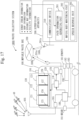
- Fig. 17 illustrates the configuration of the supervision apparatus 200.
- Fig. 18 illustrates the hardware configuration of the control device 110.
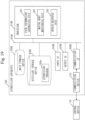
- Fig. 19 illustrates the hardware configuration of the supervision apparatus 200.
- Fig. 20 illustrates an operation sequence of the waste collection system 1000 when call information is transmitted from a movable terminal a tourist 410 has.
- Fig. 21 illustrates an operation sequence of the waste collection system 1000 when the tourist 410 speaks to the movable waste box 100.
- the control device 110 mounted on the movable waste box 100 includes an interactive unit 116
- the supervision apparatus 200 includes a speech response unit 205.
- the path information generating unit 201 In response to speech information from the tourist 410 generated by the speech response unit 205, the path information generating unit 201 generates a path through which the movable waste box 100 moves toward the tourist 410 who made a speech.
- the operation of the waste collection system 1000 when call information is transmitted from a movable terminal the tourist 410 has is described.
- the tourist 410 presses a call button, not illustrated in the drawing, of the owned movable terminal.
- the movable terminal When the call button is pressed, the movable terminal generates call information for calling the movable waste box 100, and transmits, to the supervision apparatus 200, call information including the call information and a call position, which is the terminal position of the movable terminal when the call button is pressed.
- the communication device 210 receives the call information via the network 330.
- the call information includes a time.
- the time is the time of generation of the call information.
- the speech response unit 205 Based on the call position, the speech response unit 205 identifies the current position of the movable waste box 100 subjected to dynamic monitoring by the supervision apparatus 200.
- the speech response unit 205 inputs, to the path information generating unit 201, the call position and the identified current position of the movable waste box 100.
- the path information generating unit 201 generates the path information 201a from a path connecting the call position and the current position of the movable waste box 100.
- the path information generating unit 201 transmits the generated path information 201a to the movable waste box 100 via the communication device 210.
- the communication device 190 receives the path information 201a via the network 330.
- the movement control unit 111 follows the path information 201a to cause a return to the original path via the call position.
- the control device 110 of the movable waste box 100 includes the interactive unit 116.
- speech occurrence information may be transmitted to the speech response unit 205 of the supervision apparatus 200. This process is described with reference to Fig. 21 .
- the interactive unit 116 receives a voice by audio from the tourist 410 passing in the vicinity of the movable waste box 100.
- the interactive unit 116 performs a voice recognition process on voice information acquired by a sound pickup microphone 191 mounted on the movable waste box 100. Based on the result of the voice recognition process, the interactive unit 116 determines whether the tourist 410 has an intention or desire of throwing waste away. If determining that the tourist 410 has an intention or desire of throwing waste away, the interactive unit 116 estimates an emitting direction of voice of the tourist 410 detected by the sound pickup microphone 191.
- the interactive unit 116 generates voice occurrence information including the estimated voice emitting direction, a voice occurrence time, and the current position of the movable waste box 100, and transmits the voice occurrence information via the communication device 190.
- the speech response unit 205 inputs the emitting direction of voice and the current position of the movable waste box 100 of the voice occurrence information to the path information generating unit 201.
- the path information generating unit 201 Based on the emitting direction of voice and the current position of the movable waste box 100, the path information generating unit 201 generates a stop-by path from the current position toward the emitting direction of voice. The path information generating unit 201 transmits the stop-by path via the communication device 210 to the movable waste box 100. In the movable waste box 100, the movement control unit 111 of the control device 110 changes the current movement path to the received stop-by path. The movement control unit 111 causes the movable waste box 100 to perform a turning motion toward the stop-by path.
- the movement control unit 111 recognizes the person who is present in the emitting direction of voice based on the sensor information detected by at least one of the cameras, the sonar, the millimeter wave radar, the LiDAR, and so forth in the sensor group. The movement control unit 111 tracks the image of the recognized person, and proceeds toward the person being tracked.
- the movement control unit 111 prioritizes the tracking motion. That is, assume that the movement control unit 111 determines that the movable waste box 100 is away a set distance or farther from the stop-by path by the tracking motion. In this case, the movement control unit 111 transmits the current position and the tracking direction to the supervision apparatus 200. In the supervision apparatus 200 receiving the current position and the tracking direction, the path information generating unit 201 updates the stop-by path, and transmits the updated stop-by path to the movable waste box 100.
- the interactive unit 116 may emit a response voice from a loudspeaker 192 toward the person being tracked.
- the movement control unit 111 may recognize a face image of the person being tracked and check whether the state of the mouth is changed by using facial expression recognition process. When recognizing the presence of a change, the movement control unit 111 may continue tracking. Also, by AI recognition, the movement control unit 111 may determine whether to continue tracking.
- the movement control unit 111 may emit a voice of prompting the person being tracked to throw waste away from the loudspeaker 192. Emission from the loudspeaker may be performed by the interactive unit 116.
- the movement control unit 111 may perform the tracking process by combining the detection results by the other sensors other than the cameras, such as the sonar, the millimeter wave radar, and the LiDAR. Also, in any of the following (1), (2), and (3), the interactive unit 116 emits a response voice for telling a return to the original path from the loudspeaker.
- the interactive unit 116 detects that a voice indicating an intention of a demand for throwing waste away has been emitted from a surrounding person, the interactive unit 116 transmits a signal indicating as such to the movement control unit 111. Upon receiving this signal, the movement control unit 111 continues the stop state of the movable waste box 100 as it is for the set time. Then, when confirming that no voice indicating an intention of a demand for throwing waste away has been emitted from a surrounding person, the interactive unit 117 transmits stop-by stop information indicating that a stop-by has ended and the current position to the speech response unit 205.
- the path information generating unit 201 When the stop-by stop information and the current position are received, the path information generating unit 201 generates a return path for return to the original movement path from the received current position, and transmits the movement path to the movable waste box 100.
- the control device 110 of the movable waste box 100 receives the return path via the communication device 190.
- the movement control unit 111 causes a return to the original movement path by following the return path.
- the movement control unit 111 Upon confirming that the position of the movable waste box 100 has been returned on the original movement path or to an allowable range area set in advance and regarded as being on the original movement path, the movement control unit 111 restarts the movement on the original movement path.
- the control device 110 includes the interactive unit 116, and the supervision apparatus 200 includes the speech response unit 205.
- the user of the movable waste box 100 such as the tourist 410
- usability of the movable waste box 100 is improved.
- beautification of the environment where the movable waste box 100 is used is improved.
- Embodiment 1 to Embodiment 4 have been described.
- two or more may be combined for implementation.
- one technical matter may be partially implemented.
- technical matters included in the respective embodiments may be partially combined for implementation.
Landscapes
- Engineering & Computer Science (AREA)
- Business, Economics & Management (AREA)
- Physics & Mathematics (AREA)
- General Physics & Mathematics (AREA)
- Human Resources & Organizations (AREA)
- Radar, Positioning & Navigation (AREA)
- Remote Sensing (AREA)
- Strategic Management (AREA)
- Economics (AREA)
- Mechanical Engineering (AREA)
- Development Economics (AREA)
- General Business, Economics & Management (AREA)
- Entrepreneurship & Innovation (AREA)
- Automation & Control Theory (AREA)
- Operations Research (AREA)
- Theoretical Computer Science (AREA)
- Marketing (AREA)
- Quality & Reliability (AREA)
- Accounting & Taxation (AREA)
- Aviation & Aerospace Engineering (AREA)
- Game Theory and Decision Science (AREA)
- Tourism & Hospitality (AREA)
- Finance (AREA)
- Computing Systems (AREA)
- Life Sciences & Earth Sciences (AREA)
- Sustainable Development (AREA)
- Educational Administration (AREA)
- Navigation (AREA)
- Traffic Control Systems (AREA)
- Refuse Collection And Transfer (AREA)
- Control Of Position, Course, Altitude, Or Attitude Of Moving Bodies (AREA)
- Management, Administration, Business Operations System, And Electronic Commerce (AREA)
- Manipulator (AREA)
Abstract
Description
- The present disclosure relates to a movable waste box as an autonomously-movable moving body, a waste collection system including the movable waste box, and a supervision apparatus which controls the movable waste box.
- In conventional technology, there is disclosed a waste collection management system including an acquiring unit which acquires request information regarding a waste collection request from a user, a determining unit which determines the presence or absence of an addressing moving body which can address the request information, a generating unit which generates a dispatch instruction for dispatching the addressing moving body to a collection point based on the request information when the addressing moving body is present, and a guiding unit which guides the addressing moving body to the collection point based on the dispatch instruction and causes the addressing moving body to perform collection of target waste as a target for a collection request. Here, the addressing moving body is a waste collection vehicle and automatic driving vehicle (for example, Patent Literature 1).
- Patent Literature 1:
JP 2020-87134 - In the system of
Patent Literature 1, in response to the request information from the user, a collection moving body for waste collection as an automatic driving vehicle is dispatched. However, in a place such as a tourist site or theme park, when waste such as a vacant PET bottle is desired to be thrown away, it is burdensome to take the trouble to call a waste collection vehicle, a wait time is also a nuisance, and the eyes of the surrounding people are also annoying. Thus, when waste is desired to be thrown away, a situation is preferable in which a movable waste box is making the rounds to allow waste to be thrown away. - An object of the present disclosure is to save the trouble of having to call a collection moving body for collecting waste and then wait for arrival of the collection moving body.
- The present disclosure relates to a moving body to collect waste. The moving body according to the present disclosure, includes:
- a control device having a movement control unit to cause the moving body to autonomously move by following path information indicating a path; and
- a waste box to accept waste a person who is present, partway on the path, on the path or along the path has.
- According to the present disclosure, it is possible to save the trouble of having to call a collection moving body for collecting waste and then wait for arrival of the collection moving body.
-
-
Fig. 1 is a diagram ofEmbodiment 1, illustrating the system configuration of awaste collection system 1000. -
Fig. 2 is a diagram ofEmbodiment 1, illustrating the external appearance of amovable waste box 100 included in thewaste collection system 1000. -
Fig. 3 is a diagram ofEmbodiment 1, illustrating atourist site 400 where themovable waste box 100 is used. -
Fig. 4 is a diagram ofEmbodiment 1, illustrating a specific configuration of thewaste collection system 1000. -
Fig. 5 is a diagram ofEmbodiment 1, illustrating each device mounted on themovable waste box 100. -
Fig. 6 is a diagram ofEmbodiment 1, illustrating the hardware configuration of acontrol device 110. -
Fig. 7 is a diagram ofEmbodiment 1, illustrating the hardware configuration of asupervision apparatus 200. -
Fig. 8 is a diagram ofEmbodiment 1, illustrating a path on thetourist site 400 of which themovable waste box 100 makes the rounds. -
Fig. 9 is a diagram ofEmbodiment 2, illustrating a configuration in which thesupervision apparatus 200 includes a human streaminformation generating unit 203. -
Fig. 10 is a diagram ofEmbodiment 2, illustrating the hardware configuration of thesupervision apparatus 200. -
Fig. 11 is a diagram ofEmbodiment 2, illustrating Type A to Type E as generation types ofhuman stream information 13 by the human streaminformation generating unit 203. -
Fig. 12 is a diagram ofEmbodiment 2, illustrating number lines indicating values V of thehuman stream information 13. -
Fig. 13 is a diagram ofEmbodiment 2, illustrating path information formed of an undercrowded path, an intermediate density path with a value V31, an intermediate density path with a value V32, an overcrowded path, and an intermediate density path with the value V32. -
Fig. 14 is a diagram ofEmbodiment 3, illustrating a configuration in which thesupervision apparatus 200 includes a supervision-side alert unit 204. -
Fig. 15 is a diagram ofEmbodiment 3, illustrating the hardware configuration of thecontrol device 110. -
Fig. 16 is a diagram ofEmbodiment 3, illustrating the hardware configuration of thesupervision apparatus 200. -
Fig. 17 is a diagram ofEmbodiment 4, illustrating a configuration in which thesupervision apparatus 200 includes aspeech response unit 205. -
Fig. 18 is a diagram ofEmbodiment 4, illustrating the hardware configuration of thecontrol device 110. -
Fig. 19 is a diagram ofEmbodiment 4, illustrating the hardware configuration of thesupervision apparatus 200. -
Fig. 20 is a diagram ofEmbodiment 4, illustrating an operation sequence of thewaste collection system 1000 when call information is transmitted from a movable terminal atourist 410 has. -
Fig. 21 is a diagram ofEmbodiment 4, illustrating an operation sequence of thewaste collection system 1000 when thetourist 410 speaks to themovable waste box 100. - In the description and the drawings of the embodiments, the same components and corresponding components are provided with the same reference character. Description of the components provided with the same reference character is omitted or simplified as appropriate. In the following embodiments, a "unit" may be read as a "circuit", "step", "procedure", "process", or "circuitry" as appropriate.
- A
waste collection system 1000 ofEmbodiment 1 is described with reference toFig. 1 to Fig. 8 . -
Fig. 1 illustrates the system configuration of thewaste collection system 1000. -
Fig. 2 illustrates an external appearance of amovable waste box 100 included in thewaste collection system 1000. -
Fig. 3 illustrates atourist site 400 where themovable waste box 100 is used. - As illustrated in
Fig. 1 , thewaste collection system 1000 includes a plurality ofmovable waste boxes 100 and asupervision apparatus 200. Eachmovable waste box 100 and thesupervision apparatus 200 communicate via anetwork 330. Themovable waste box 100 receivespath information 201a transmitted from a pathinformation generating unit 201 of thesupervision apparatus 200, and autonomously moves by following thepath information 201a. Note that the pathinformation generating unit 201 transmits thepath information 201a via acommunication interface 960B, which will be described below. Themovable waste box 100 is referred to as an AMR (autonomous mobile robot). Themovable waste box 100 is used on a site such as a tourist site or theme park. In the following description, themovable waste box 100 is described when used on thetourist site 400, by way of example. Themovable waste box 100 makes the rounds of thetourist site 400. - As illustrated in
Fig. 2 , themovable waste box 100 includes awaste box 120. Themovable waste box 100 moves with fourtires 101. Note inFig. 2 that the rightrear tire 101 is not viewed. Also, themovable waste box 100 includes, in addition to thewaste box 120, various sensors for autonomous movement such as aGNSS antenna 605,cameras 181, asonar 182, amillimeter wave radar 183, and a LiDAR 184, and these sensors will be described further below. Thewaste box 120 is formed of aseparate waste box 121, aseparate waste box 122, and aseparate waste box 123. A different waste box has an opening formed, and waste can be put from the opening. On a side surface of themovable waste box 100, a waste type of the separate waste box is displayed, such asburnable waste 124a,plastic waste 124b, drinkingcup waste 124c. The display ofburnable waste 124a corresponds to theseparate waste box 121, the display ofplastic waste 124b corresponds to theseparate waste box 122, and the display of drinkingcup waste 124c corresponds to theseparate waste box 123. - In
Fig. 3 , a plurality of tourists are walking on a certain tourist site where a plurality ofshops 320 are present. Themovable waste box 100 travels around thetourist site 400 at a speed on the order of 1 km per hour or 2 km per hour. Themovable waste box 100 makes the rounds of thetourist site 400 by following a path indicated by thepath information 201a. In the vicinity of eachshop 320, astreet camera 310 is installed. Images taken by thestreet cameras 310 can be used for processing such as generation ofhuman stream information 13 and waste extraction, which will be described further below. -
Fig. 4 illustrates a specific configuration of thewaste collection system 1000. Themovable waste box 100 includes acontrol device 110, thewaste box 120, and the sensor group including thecameras 181. Themovable waste box 100 receives a positioning signal from aGNSS satellite 40 to measure a position, and performs self position estimation by using the positioning result and the measurement result of the sensor group. Thesupervision apparatus 200 communicates with themovable waste box 100 via thenetwork 330. Thecontrol device 110 transmitswaste collection information 100b indicating a situation of waste collection to thesupervision apparatus 200 via thenetwork 330. Thesupervision apparatus 200 transmits thepath information 201a to themovable waste box 100. The pathinformation generating unit 201 of thesupervision apparatus 200 acquires, from outside thesupervision apparatus 200, information about human streams, shop information, dynamic map information, and information about facilities. Themovable waste box 100 and thesupervision apparatus 200 are specifically described below. -
Fig. 5 illustrates each device mounted on themovable waste box 100. Themovable waste box 100 includes thecontrol device 110, anautonomous movement device 170, and aunified sensor unit 180. - The
unified sensor unit 180 includes theGNSS antenna 605, thecameras 181, thesonar 182, themillimeter wave radar 183, theLiDAR 184, aGNSS positioning device 185, and asensor fusion unit 186. Theunified sensor unit 180 is a unit which measures data for themovable waste box 100 to autonomously move. As illustrated inFig. 4 , thecameras 181 are installed on a front side and a rear side. Those from thecameras 181 to theLiDAR 184 may be represented as a sensor group. TheGNSS antenna 605 is connected to theGNSS positioning device 185 to configure a locator (position assessment device). Measurement data of the sensor group and the positioning result of theGNSS positioning device 185 are inputted to thesensor fusion unit 186. Thesensor fusion unit 186 inputs unified information 188 acquired by unifying the inputted data to amovement control unit 111. - The
control device 110 is a device which controls autonomous movements of themovable waste boxes 100 and also supports waste collection to thewaste boxes 120. Thecontrol device 110 includes themovement control unit 111, astorage device 112, awaste extracting unit 113, and a wasteamount control unit 114. Themovement control unit 111 has unified information 188 inputted from theunified sensor unit 180. Based on the unified information 188, thepath information 201a held in thestorage device 112, and an instruction from thesupervision apparatus 200, themovement control unit 111 generates autonomousmovement control information 111a for theautonomous movement device 170 to cause anymovable waste box 100 to autonomously move. Thewaste extracting unit 113 extracts waste by using the sensor group. Waste extraction will be described further below. The wasteamount control unit 114 monitors the accommodation capacity of waste of theseparate waste box 121, theseparate waste box 122, and theseparate waste box 123. Thestorage device 112 has stored therein a high-precision map received from thesupervision apparatus 200 and point-group data measured by theLiDAR 184, and has them held in a high-precision map and point-group database (high-precision map/point-group DB) 119. Also, thestorage device 112 has stored therein learnedmodel 113a and thepath information 201a received from thesupervision apparatus 200. Thestorage device 112 is implemented by anauxiliary storage device 930A. - The
autonomous movement device 170 causes anymovable waste box 100 to autonomously move based on the autonomousmovement control information 111a. Specifically, theautonomous movement device 170 causes themovable waste box 100 to autonomously move by controlling a traveling mechanism included in themovable waste box 100, such as a motor or steering mechanism not illustrated in the drawings. Note that eachmovable waste box 100 has a battery as a motive power source and eachmovable waste box 100 is so called an electric automobile. -
Fig. 6 illustrates the hardware configuration of thecontrol device 110. Thecontrol device 110 is a computer. Thecontrol device 110 includes aprocessor 910A. Thecontrol device 110 includes, in addition to theprocessor 910A, other hardware including amain storage device 920A, theauxiliary storage device 930A, aninput interface 940A, anoutput interface 950A, and acommunication interface 960A. Theprocessor 910A is connected to the other hardware via asignal line 970A to control the other hardware. - The
control device 110 includes themovement control unit 111, thewaste extracting unit 113, and the wasteamount control unit 114 as functional components. The functions of themovement control unit 111, thewaste extracting unit 113, and the wasteamount control unit 114 are implemented by acontrol program 110a. - The
processor 910A is a device which executes thecontrol program 110a. Thecontrol program 110a is a program which implements the functions of themovement control unit 111, thewaste extracting unit 113, and the wasteamount control unit 114. Theprocessor 910A is an IC (Integrated Circuit) which performs arithmetic process. Specific examples of theprocessor 910A are a CPU (Central Processing Unit), a DSP (Digital Signal Processor), and a GPU (Graphics Processing Unit). - Specific examples of the
main storage device 920A are an SRAM (Static Random Access Memory) and a DRAM (Dynamic Random Access Memory). Themain storage device 920A retains arithmetic operation results of theprocessor 910A. - The
auxiliary storage device 930A is a non-volatile storage device which retains data. A specific example of theauxiliary storage device 930A is an HDD (Hard Disk Drive). Also, theauxiliary storage device 930A may be a portable recording medium such as an SD (registered trademark) (Secure Digital) memory card, NAND flash, flexible disk, optical disk, compact disk, Blu-ray (registered trademark) disk, or DVD (Digital Versatile Disk). Theauxiliary storage device 930A has stored therein the high-precision map and point-group database 119, the learnedmodel 113a, thepath information 201a, and thecontrol program 110a. - The
input interface 940A is a port to which data is inputted from each device. To theinput interface 940A, theunified sensor unit 180 is connected. Theoutput interface 950A is a port to which various devices are connected and through which data is caused by theprocessor 910A to be outputted to various devices. To theoutput interface 950A, theautonomous movement device 170 is connected. Thecommunication interface 960A is a communication port for the processor to communicate with another device. To thecommunication interface 960A, acommunication device 190 is connected. Via thecommunication device 190, thecontrol device 110 communicates with thesupervision apparatus 200. Specifically, with thecommunication device 190 communicating with acommunication device 210, which will be described further below, included in thesupervision apparatus 200, communication between thecontrol device 110 and thesupervision apparatus 200 is established. - The
control device 110 may include a plurality of processors which replace theprocessor 910A. The plurality of these processors share execution of thecontrol program 110a. As with theprocessor 910A, each processor is a device which executes thecontrol program 1 10a. Data, information, signal values, and variable values to be used, processed, or outputted by thecontrol program 110a are stored in themain storage device 920A, theauxiliary storage device 930A, or a register or cache memory in theprocessor 910A. - The
control program 110a is a program which causes a computer to perform each process, each procedure, or each step acquired by reading the "unit" of each of themovement control unit 111, thewaste extracting unit 113, and the wasteamount control unit 114 as a "process", "procedure", or "step". - Also, a control method is a method to be performed by the
control device 110 as a computer executing thecontrol program 110a. Thecontrol program 110a may be provided as being held in a computer-readable recording medium or may be provided as a program product. -
Fig. 7 illustrates the hardware configuration of thesupervision apparatus 200. Thesupervision apparatus 200 is a computer having a configuration similar to that of thecontrol device 110. Thesupervision apparatus 200 includes aprocessor 910B and so forth as hardware. Since the configuration of thesupervision apparatus 200 ofFig. 7 is similar to that of thecontrol device 110 ofFig. 6 , as for reference characters of the processor and so forth, B is provided instead of A inFig. 6 . Only portions different from thecontrol device 110 ofFig. 6 are described. - The
supervision apparatus 200 includes the pathinformation generating unit 201 and a movingbody monitoring unit 202 as functional components. The functions of the pathinformation generating unit 201 and the movingbody monitoring unit 202 are implemented by asupervision program 200a. Thesupervision program 200a is executed by theprocessor 910B. Anauxiliary storage device 930B has stored therein thesupervision program 200a. Thesupervision program 200a is a program which causes a computer to perform each process, each procedure, or each step acquired by reading the "unit" of each of the pathinformation generating unit 201 and the movingbody monitoring unit 202 as a "process", "procedure", or "step". Also, an infection method is a method to be performed by thesupervision apparatus 200 as a computer executing thesupervision program 200a. Thesupervision program 200a may be provided as being held in a computer-readable recording medium or may be provided as a program product. To thecommunication interface 960B, thecommunication device 210 is connected. Thesupervision apparatus 200 communicates with thecontrol device 110 via thecommunication device 210. Thecommunication device 210 is illustrated also inFig. 2 . - The operation of the
movable waste box 100 is specifically described below. - The
movable waste box 100 illustrated inFig. 2 is a moving body which collects waste. Themovement control unit 111 included in thecontrol device 110 causes themovable waste box 100 to autonomously move by following thepath information 201a indicating a path. - Normally, the
movable waste box 100 autonomously travels at a speed equal to or slow than 6 km per hour. For example, themovable waste box 100 travels at a speed between 1 km per hour and 2 km per hour. However, the speed of autonomous traveling is simply an example. The speed of themovable waste box 100 by autonomous traveling is not limited. Thewaste box 120 is a waste box which accepts waste a person who is present, partway on a path, on the path or along the path has. Themovable waste box 100 travels at a low speed between 1 km per hour and 2 km per hour, and collects waste partway on a traveling path. Thus, it is possible to beautify thetourist site 400 without obstructing thetourist 410. -
Fig. 8 illustrates a path on thetourist site 400 of which themovable waste box 100 makes the rounds. On thetourist site 400, the plurality ofshops 320 are present. InFig. 8 , the plurality ofshops 320 are classified into five shops from ashop 320a to ashop 320e. Normally, themovable waste box 100 follows thepath information 201a to make the rounds of apath 401 specified by points P1, P2, P3, P4, and P1 in aforwarding direction 100a. As will be described further below, depending on the accommodation capacity of waste or the like, themovable waste box 100 makes the rounds of apath 402 specified by points P6, P2, P3, P6, and P6. In this case, themovable waste box 100 haspath information 201b corresponding to thepath 402, and can make the rounds of thepath 402 by switching thepath information 201a to thepath information 201b. - The
movable waste box 100 has a human sensor which detects a movement of a person. As a human sensor, the sensor group theunified sensor unit 180 has can be used. When the human sensor detects a state in which a person approaches anymovable waste box 100, themovement control unit 111 causes the speed of themovable waste box 100 to be decreased. That is, as illustrated inFig. 3 , when the sensor group of theunified sensor unit 180 detects atourist 410a approaching themovable waste box 100, themovement control unit 111 transmits, to theautonomous movement device 170, autonomousmovement control information 111a including a speed reduction instruction. Aspeed control unit 171 follows the speed reduction instruction to decrease the speed of themovable waste box 100. For example, when themovable waste box 100 is traveling at 1 to 2 km/h per hour at normal times, the speed is decreased so that themovable waste box 100 is caused to travel at 0 to 1 km/h per hour at normal times. - The speed reduction instruction may be a stop instruction. In the case of the stop instruction, the
speed control unit 171 stops the movement of themovable waste box 100. - Also, when the sensor group as a human sensor detects a state in which a person is going away from any
movable waste box 100, themovement control unit 111 causes the speed of themovable waste box 100 to be increased. In this case, themovement control unit 111 transmits, to theautonomous movement device 170, autonomousmovement control information 111a including a speed increase instruction. Thespeed control unit 171 follows the speed increase instruction to increase the speed of themovable waste box 100. For example, when themovable waste box 100 is traveling at 0 to 1 km/h per hour at normal times, the speed is decreased so that themovable waste box 100 is caused to travel at 1 to 2 km/h per hour at normal times. - Since the
movable waste box 100 changes its speed with a person approaching or going away, there is an effect that thetourists 410 can easily throw waste away. - The
control device 110 has a plurality of pieces of path information stored in thestorage device 112. InFig. 6 , theauxiliary storage device 930A as thestorage device 112 has held therein two path information, thepath information 201a and thepath information 201b. In accordance with the accommodation capacity of waste accumulated in thewaste box 120, themovement control unit 111 selects path information from among the plurality of pieces of path information. The accommodation capacity of waste can be detected by an accommodation capacity sensor arranged in thewaste box 120. Note that the accommodation capacity sensor can be replaced by a weight sensor, which will be described further below. The accommodation capacity sensor is arranged in each of theseparate waste box 121, theseparate waste box 122, and theseparate waste box 123. - For example, when the
separate waste box 121 for collecting burnable waste has waste exceeding a threshold amount of accommodatable waste, themovement control unit 111 selects thepath information 201b, and makes the rounds of the path 402 (Fig. 8 ) by following thepath information 201b. In this case, thepath information 201b is associated with attribute information indicating that the amount of emission of burnable waste is small. Also, the threshold value of burnable waste is determined with a margin of waste accommodation, and waste can be collected to some extent even if burnable waste is emitted on thepath 402. Process when the waste box is filled with burnable waste will be described further below. In this manner, since themovable waste box 100 changes the path depending on the accommodation capacity of waste, thewaste box 120 can be effectively used. - The
movable waste box 100 as a moving body includes thecameras 181 as an image-taking device which takes an image of the vicinity. Theauxiliary storage device 930A of thecontrol device 110 has held therein the learnedmodel 113a. The learnedmodel 113a is a model for extracting waste from an image on which waste appears. Thewaste extracting unit 113 of thecontrol device 110 extracts waste by using the learnedmodel 113a from the image taken by anycamera 181 and, when waste is extracted, outputs a waste extraction signal. - The
waste extracting unit 113 transmits, as a waste extraction signal, an extraction notification that waste has been extracted to thesupervision apparatus 200 which manages themovable waste box 100. Specifically, thewaste extracting unit 113 transmits an extraction notification to thesupervision apparatus 200 via thecommunication interface 960A. The extraction notification includes a waste extraction time and a waste extraction location. A supervision station, not illustrated in the drawings, having thesupervision apparatus 200 can notify an administrator of thetourist site 400 that waste has been extracted. - Alternatively, as illustrated in
Fig. 8 , themovable waste box 100 may include anarm mechanism 150 which catches and accommodates waste into thewaste box 120. Upon outputting a waste extraction signal, thewaste extracting unit 113 may cause waste the image of which has been taken to be accommodated in thewaste box 120 by using thearm mechanism 150. - As described above, since the
control device 110 extracts waste by using the learnedmodel 113a, waste can be efficiently collected. - Note that the learned
model 113a is generated by the pathinformation generating unit 201 of thesupervision apparatus 200. The pathinformation generating unit 201 learns images of waste by, for example, supervised learning, and generates the learnedmodel 113a. The generated learnedmodel 113a is held in theauxiliary storage device 930A of thecontrol device 110. - Also, the learned
model 113a may be able to extract a person such as atourist 410b having waste illustrated inFig. 3 from any image. Thewaste extracting unit 113 extracts a person having waste from any image taken by anycamera 181 as an image-taking device in the vicinity of the path indicated by the path information by using the learnedmodel 113a. When a person having waste is extracted from any image by thewaste extracting unit 113, themovement control unit 111 causes themovable waste box 100 to leave the path and approach the person having waste. Specifically, themovement control unit 111 generates autonomousmovement control information 111a indicating that themovable waste box 100 approaches the person having waste for output to theautonomous movement device 170. - If collection of waste from the person having waste has been confirmed by the sensor group, the
movement control unit 111 causes themovable waste box 100 to be returned to the original path. Specifically, if collection of waste from the person having waste has been confirmed by the sensor group, themovement control unit 111 generates autonomousmovement control information 111a for making an instruction of returning to the original path for output to theautonomous movement device 170. - In this manner, since the
movable waste box 100 approaches the person having waste, the person having waste can easily throw waste away, and beautification of thetourist site 400 is improved. - The
movable waste box 100 includes a waste box monitoring device which monitors thewaste box 120. The waste box monitoring device can be implemented by the sensor group such as thecameras 181, thesonar 182, themillimeter wave radar 183, and theLiDAR 184. For example, as a waste box monitoring device, as illustrated inFig. 2 , a sensor forwaste drop detection 187 is arranged on an upper portion of an opening at the center of thewaste box 120. Thesensor 187 is configured of, for example, a camera, an infrared sensor, a sonar, an optical sensor, or the like. This sensor forwaste drop detection 187 is arranged also at the same position on the right side. By using the monitoring result of the waste box monitoring device, thewaste extracting unit 113 determines whether there is any waste with its position changed from the inside of thewaste box 120 to the outside of thewaste box 120. - Upon determining that there is any waste with its position changed from the inside of the
waste box 120 to the outside of thewaste box 120, thewaste extracting unit 113 transmits an alert notification to thesupervision apparatus 200 which manages themovable waste box 100. The alert notification includes a time and location of detection of the waste drop. The supervision station where thesupervision apparatus 200 is present notifies the administrator of thetourist site 400 of the details of the alert notification. With this, beautification of thetourist site 400 is improved. - Alternatively, as illustrated in
Fig. 8 , themovable waste box 100 may include thearm mechanism 150 which catches and accommodates waste into thewaste box 120. In this case, when determining that there is any waste with its position changed from the inside of thewaste box 120 to the outside of thewaste box 120, thewaste extracting unit 113 identifies, based on the learnedmodel 113a, the waste with its position changed and, by using thearm mechanism 150, causes the waste with its position changed to be collected inside of thewaste box 120. With this, beautification of thetourist site 400 is improved. - Note that a waste drop determination can be made as follows.
- The
waste extracting unit 113 can detect a waste drop from a weight sensor installed in thewaste box 120. - In
Fig. 4 ,weight sensors separate waste box 121, theseparate waste box 122, and theseparate waste box 123 are illustrated. Theweight sensors weight sensor 130. - The
waste extracting unit 113 can detect waste by making a comparison between a high-precision map as a three-dimensional map and information about a point group in real time acquired by the LiDAR 184 (point-group database). This process can be used for any waste dropped on roads in general. By further using the learnedmodel 113a, when an image corresponding to a difference in the point group is present, thewaste extracting unit 113 may determine whether data of the point group represents waste. - As a waste box monitoring device, the
weight sensor 130 which detects the weight of waste for each separate waste box may be arranged inside the device of themovable waste box 100. Also, an infrared sensor or the like which detects, for each separate waste box, the height of waste accumulated inside the waste box or the position of waste positioned at the highest may be arranged on a back surface of a ceiling part of themovable waste box 100. If waste of part of separate waste increases based on the detection result of theweight sensor 130, the infrared sensor, or the like, after the capacity of another separate waste box is detected, the capacity of the separate waste box with increased waste is increased. Specifically, the process is as follows. As illustrated inFig. 2 , thewaste box 120 is divided into theseparate waste box 121, theseparate waste box 122, and theseparate waste box 123 for each type of waste. Theseparate waste box 121, theseparate waste box 122, and theseparate waste box 123 can have their accommodation capacity of waste changed by control. Specifically, the process is as follows. In thewaste box 120, a partitionplate driving device 129 is arranged. Receiving control, the partitionplate driving device 129 can movepartition plates movable waste box 100. With this, the capacities of theseparate waste box 121, theseparate waste box 122, and theseparate waste box 123 can be changed. Via control of the partitionplate driving device 129, the wasteamount control unit 114 of thecontrol device 110 controls the accommodation capacity of waste accommodatable in each separate waste box. With this, use efficiency of thewaste box 120 is improved. - The operation of the
waste collection system 1000 is described below, with attention being paid to thesupervision apparatus 200. - The
movable waste box 100 illustrated inFig. 4 autonomously moves at a speed equal to or slower than 6 km per hour by following path information indicating a path. Themovable waste box 100 includes thewaste box 120 which accepts waste a person who is present, partway on a path, on the path or along the path has. Thesupervision apparatus 200 has the pathinformation generating unit 201 which generates path information and transmits the path information to a moving body. - The path
information generating unit 201 generates path information based on streams of people in an area such as thetourist site 400 where themovable waste box 100 is scheduled to move.Human stream information 13 indicating streams of people can be acquired from thestreet camera 310 illustrated inFig. 3 . Alternatively, it can be acquired from an institution such as a corporation which collects thehuman stream information 13. The pathinformation generating unit 201 generates path information indicating that the rounds are made in a place with many streams of people, thereby allowing waste to be efficiently collected from thetourists 410 on thetourist site 400. Note that the path information may include thehuman stream information 13 indicating a stream of people. - The path
information generating unit 201 may generate path information based on a facility including theshops 320 arranged in an area where themovable waste box 100 is scheduled to move. Specifically, inFig. 8 , if theshop 320d and theshop 320e are popular shops where people gather, the pathinformation generating unit 201 generates a path including the points P5, P6, P2, and P3. Since more people gather in popular shops, by including the locations of the popular shops in the path, it is possible to efficiently collect waste from thetourists 410. The path information can be acquired from a device outside thesupervision apparatus 200. - The
auxiliary storage device 930B has stored therein waste emission information indicating waste emission situations at a plurality of locations in the area where themovable waste box 100 is scheduled to move. The pathinformation generating unit 201 may generate path information based on the waste emission information stored in theauxiliary storage device 930B. With the pathinformation generating unit 201 referring to the waste emission information and generating path information including locations with large emission amounts of waste, waste can be efficiently collected. The waste emission information has recorded thereon, for example, a waste emission amount with respect to time for each location. The pathinformation generating unit 201 can acquire the waste emission information from a device outside thesupervision apparatus 200. The waste emission information includes, as described above, time information indicating a time when waste is emitted. With this, path information effective for waste collection can be generated. - Note that note that, for generation of path information, a learned model for generating path information may be used. Specifically, the process is as follows. By taking, as training data, at least any of the image taken by the
street camera 310 illustrated inFig. 3 , information about human streams and so forth illustrated inFig. 4 , or times and locations when waste is emitted on thetourist site 400 and information such as waste information associated with the accommodation capacity of emitted waste acquired from outside of thesupervision apparatus 200, the pathinformation generating unit 201 learns the locations and times when more waste is emitted to generate a learned model for path information generation. By using this learned model, the pathinformation generating unit 201 generates path information including a location and time where and when themovable waste box 100 should make the rounds in a prioritized manner. - As illustrated in
Fig. 1 , thewaste collection system 1000 includes the plurality ofmovable waste boxes 100. The pathinformation generating unit 201 generates different path information for eachmovable waste box 100, thereby covering waste collection on thetourist site 400 as a scheduled area where arrangement of the plurality ofmovable waste boxes 100 is scheduled. With this, waste on thetourist site 400 can be completely collected. - As the accommodation capacity of waste in the
waste box 120 exceeds a threshold value, themovable waste box 100 transmits an excess signal to thesupervision apparatus 200. - When receiving the excess signal, the path
information generating unit 201 transmits a movement destination instruction for making an instruction of a movement destination to a transmission moving body, which is themovable waste box 100 transmitting the excess signal, to cause the transmission moving body to move to the movement destination. For example, the movement destination is astorage warehouse 340 illustrated inFig. 8 . - To replace the transmission moving body by the
movable waste box 100 different from the transmission moving body, the pathinformation generating unit 201 transmits path information identical to the path information transmitted to the transmission moving body to the differentmovable waste box 100. With this, the transmission moving body filled with waste can be changed to the differentmovable waste box 100. - The
supervision apparatus 200 has the movingbody monitoring unit 202 that monitors the movement state of themovable waste box 100 to control the movement state of themovable waste box 100 based on the monitoring result. Position information on which monitoring is based is transmitted from themovable waste box 100. The position information is associated with a presence time and a presence position. From the position information and themovable waste box 100 the image of which was taken by thestreet camera 310, the movingbody monitoring unit 202 can control the movement state of themovable waste box 100. In this manner, by remotely controlling themovable waste box 100, thetourist site 400 can be efficiently beautified. - According to the
waste collection system 1000 ofEmbodiment 1, themovable waste box 100 as an automatic traveling vehicle equipped with a waste box itself is caused to travel along the movement path of thetourists 410, and thus it is possible to save thetourists 410 trouble of finding a waste box, and improve beautification of thetourist site 400. - The
waste collection system 1000 ofEmbodiment 2 is described with reference toFig. 9 to Fig. 14 . Since thewaste collection system 1000 ofEmbodiment 2 is identical to that ofFig. 1 , description is omitted. InEmbodiment 2, thewaste collection system 1000 includes a human streaminformation generating unit 203. The functions of the human streaminformation generating unit 203 may be arranged in thesupervision apparatus 200 or may be arranged in another device different from thesupervision apparatus 200 and outside thesupervision apparatus 200. However, the human streaminformation generating unit 203 is arranged inside thewaste collection system 1000. In the following, a configuration is described, by way of example, in which thesupervision apparatus 200 includes the human streaminformation generating unit 203. -
Fig. 9 illustrates the configuration in which thesupervision apparatus 200 includes the human streaminformation generating unit 203. -
Fig. 10 illustrates the hardware configuration of thesupervision apparatus 200. -
Fig. 11 illustrates Type A to Type E as generation types ofhuman stream information 13 by the human streaminformation generating unit 203. - The human stream
information generating unit 203 generates thehuman stream information 13 based on information such as external input information or sensing information of a sensor X. The sensor X will be described further below. - The human stream
information generating unit 203 can generate thehuman stream information 13 from image information, position information of a person, and speed information of a person acquired by the sensor X mounted on themovable waste box 100 or the sensor X provided outside themovable waste box 100. The "sensor X provided outside themovable waste box 100" means the sensor X not mounted on themovable waste box 100. - The sensor X is described.
- The sensor X is configured of one or plurality of the following (1) to (6):
- (1) the
street camera 310, - (2) the
cameras 181 mounted on themovable waste box 100, - (3) a camera mounted on an onboard PMV (Personal Mobility Vehicle),
- (4) a camera mounted on a MaaS (Mobility as a Service),
- (5) one or plurality of sensors among a speed sensor, an acceleration sensor, and a position sensor mounted on a movable terminal typified by a smartphone or mobile device owned by a tourist (hereinafter referred to as a movable terminal), and
- (6) user information of MaaS, hotels, or shops.
- Note that the movable terminal is a terminal device.
- Other than the vicinity of the
shops 320, thestreet camera 310 may be arranged at a location such as (1) to (4) below: - (1) a passage scheduled path of the
movable waste box 100, - (2) a passage scheduled path of the PMV,
- (3) a facility people who can emit waste come to and go out from, such as a "hotel, exhibition facility, amusement facility, spa facility, or public hall", and
- (4) a place where people pass and waste cannot be left, such as a "tour route, park, forest road, or field" or the vicinity of these places.
- As illustrated in
Fig. 11 , based on first image information acquired by thestreet camera 310, second image information acquired by thecameras 181 of themovable waste box 100, and third image information acquired by the camera mounted on the PMV, the human streaminformation generating unit 203 recognizes a person from these images and tracks the person. Then, the human streaminformation generating unit 203 measures items such as a position, speed, or change in position of the tracked person, or the number of people. By measuring these items, from, for example, "human presence density, human average movement speed, human moving direction, and human moving flux" per cubic meter, for each unit space, the human streaminformation generating unit 203 can generate thehuman stream information 13 indicating an evaluation index of the human stream. As an evaluation index of the human stream, that is, thehuman stream information 13, a value for numerical value evaluation of a "level of a degree of off-peak/congestion and density of the moving flux" can be used. - Also, the human stream
information generating unit 203 can generate thehuman stream information 13 based on the position information and the speed information acquired by the movable terminal owned by the tourist. - Also, by using at least any of the following (1), (2), and (3), the human stream
information generating unit 203 can measure the number of theme-park users (tourists) at a theme park per unit time and can find thehuman stream information 13 from the number of people for each moving body or each location. - (1) position information of a "moving body such as MaaS or automobile",
- (2) the number of passengers getting-on/off a moving body such as a vehicle or train, and
- (3) "user information of a user at a facility such as a hotel or shop".
- In the following, the operation of the path
information generating unit 201 ofEmbodiment 2 in cooperation with the human streaminformation generating unit 203 is described. -
Fig. 12 illustrates number lines indicating values V of thehuman stream information 13. In the pathinformation generating unit 201, details of number lines ofFig. 12 are set. A path with a value V equal to or smaller than a threshold value V1 is an undercrowded path with less human streams. A path with a value V equal to or larger than a threshold value V2 is an overcrowded path with more human streams. A path with a value between the threshold value V1 and the threshold value V2 is an intermediate density path. The intermediate density paths include one section with a value V represented by one value between V1 and V2 and a plurality of sections with a value V represented by a plurality of values between V1 and V2. The intermediate density path on an upper side ofFig. 12 indicates one section with a value V represented by one value, a value V31. The intermediate density path on a lower side ofFig. 12 indicates two sections with a value V represented by two values, values V31 and V31. In accordance with the undercrowded path passing through an area where the value V is equal to or smaller than the threshold value V1, the overcrowded path passing through an area where the value V is equal to or larger than the threshold value V2, and the intermediate density path passing through one section as an area with the value V being one representative value or a plurality of sections as areas with a plurality of representative values, the pathinformation generating unit 201 schedules pass passage priorities and a passing order. When a larger numerical value of priority is set to have larger priority, in the example ofFig. 12 , the pathinformation generating unit 201 setspriority 4 to the overcrowded path,priority 3 to the intermediate density path with V32,priority 2 to the intermediate density path with V32, andpriority 1 to the undercrowded path. - For example, the path
information generating unit 201 refers to the set priorities and sets path information as a passage route of themovable waste box 100 so that the number of passages of the overcrowded path of themovable waste box 100 increases per unit time or per use time of a facility the tourists use or the number of passages of the undercrowded path decreases per unit time or per use time. -
Fig. 13 illustrates an example in which the pathinformation generating unit 201 generates path information formed of, from left, an undercrowded path, an intermediate density path with the value V31, an intermediate density path with the value V32, an overcrowded path, and an intermediate density path with the value V32. In this path information, the order of passage is set. S1 to S17 represents the order of passages. S1 represents a start, and S17 represents an end. According to the path information ofFig. 13 , themovable waste box 100 passes the overcrowded path six times, passes each intermediate density path with the value V32 four times, passes the intermediate density path with the value V31 twice, and passes the undercrowded path once. With this, themovable waste box 100 can efficiently collect waste in accordance with density. - In the
waste collection system 1000 ofEmbodiment 2, thesupervision apparatus 200 includes the human streaminformation generating unit 203 which generates thehuman stream information 13. And, the pathinformation generating unit 201 generates path information by using thehuman stream information 13 generated by the human streaminformation generating unit 203. Thus, the human stream information is generated inside thewaste collection system 1000, and path information is generated from the human stream information generated inside thewaste collection system 1000. Therefore, correct human stream information necessary for thewaste collection system 1000 can be quickly acquired. Also, since path information is generated from the human stream information that is correct for thewaste collection system 1000, efficient waste collection can be made. Also, the degree of satisfaction of tourists on a waste emission side is improved. - The
waste collection system 1000 ofEmbodiment 3 is described with reference toFig. 14 to Fig. 16 . - The system configuration of the
waste collection system 1000 ofEmbodiment 3 is identical to that ofFig. 1 . -
Fig. 14 illustrates the configuration of thesupervision apparatus 200. -
Fig. 15 illustrates the hardware configuration of thecontrol device 110. -
Fig. 16 illustrates the hardware configuration of thesupervision apparatus 200. InEmbodiment 3, themovable waste box 100 and thesupervision apparatus 200 issue an alert in accordance with the weight of waste or the capacity of waste of themovable waste box 100. Themovable waste box 100 includes a movement-side alert unit 115 which issues an alert. Thesupervision apparatus 200 includes a supervision-side alert unit 204 which issues an alert. As illustrated inFig. 14 ,weight sensors separate waste box 121, theseparate waste box 122, and theseparate waste box 123, respectively. Also,accommodation capacity sensors separate waste box 121, theseparate waste box 122, and theseparate waste box 123, respectively. The weight sensors are represented as aweight sensor 150 unless distinction is required. The accommodation capacity sensors are represented as an accommodation capacity sensor 140 unless distinction is required. - The movement-
side alert unit 115 issues an alert based on the detection result of the sensor which detects at least any of the weight or the accommodation capacity of waste accumulated in the waste box. - The movement-
side alert unit 115 acquires detection information of the weight of waste measured by theweight sensor 150 from theweight sensor 150 or detection information of the accommodation capacity of waste measured by the accommodation capacity sensor 140 from the accommodation capacity sensor 140. The movement-side alert unit 115 determines based on the acquired detection information whether the weight or capacity of waste has a value equal to or larger than an allowable value. If the value of the weight or capacity of waste exceeds the allowable value, the movement-side alert unit 115 outputs an alert sound indicating that the waste box is full to a loudspeaker, not illustrated, connected to the output IF 960A, or sound or display to a display device, not illustrated, connected to the output IF 960A. - When the weight of waste or the capacity of waste exceeds the allowable value, the movement-
side alert unit 115 transmits a full signal indicating that the waste box is filled with waste to thesupervision apparatus 200. Upon receiving the full signal, although not illustrated in the drawings, the supervision-side alert unit 204 issues an alert message and an alert sound to a monitoring monitor screen of the supervision system or a loudspeaker of the supervision system. - As for measurement of the accommodation capacity by the accommodation capacity sensor 140 which detects an accommodation capacity, the accommodation capacity can be estimated from an estimated capacity acquired by multiplying the uppermost height of waste by the surface area of the waste box from an image of the inside of the waste box. Alternatively, an optical sensor may be provided on an upper inner surface of the inside of the waste box and, when the optical sensor detects waste, it may be detected that the accommodation capacity is equal to or larger than a predetermined threshold value. In this case, the optical sensor corresponds to the capacity sensor.
- In the
waste collection system 1000 ofEmbodiment 3, thecontrol device 110 includes the movement-side alert unit 115 which issues an alert. Also, thesupervision apparatus 200 includes the supervision-side alert unit 204 which issues an alert. Thus, since the user such as a tourist using themovable waste box 100 can know that the waste box is filled with waste, the possibility of throwing waste away into themovable waste box 100 is decreased. Thus, the aesthetic appearance of themovable waste box 100 can be maintained. Also, the waste accommodation capability of themovable waste box 100 can be protected from overflowing. Also, the administrator on asupervision apparatus 200 side which manages themovable waste box 100 can know that themovable waste box 100 is filled with waste. Thus, with the pathinformation generating unit 201 generating a return path and transmitting the return path to thecontrol device 110 of themovable waste box 100 filled with waste, themovable waste box 100 can be caused to be returned to a garage. -
Embodiment 4 is described with reference toFig. 17 to Fig. 21 . -
Fig. 17 illustrates the configuration of thesupervision apparatus 200. -
Fig. 18 illustrates the hardware configuration of thecontrol device 110. -
Fig. 19 illustrates the hardware configuration of thesupervision apparatus 200. -
Fig. 20 illustrates an operation sequence of thewaste collection system 1000 when call information is transmitted from a movable terminal atourist 410 has. -
Fig. 21 illustrates an operation sequence of thewaste collection system 1000 when thetourist 410 speaks to themovable waste box 100. In thewaste collection system 1000 ofEmbodiment 4, thecontrol device 110 mounted on themovable waste box 100 includes aninteractive unit 116, and thesupervision apparatus 200 includes aspeech response unit 205. - In response to speech information from the
tourist 410 generated by thespeech response unit 205, the pathinformation generating unit 201 generates a path through which themovable waste box 100 moves toward thetourist 410 who made a speech. With reference toFig. 20 , the operation of thewaste collection system 1000 when call information is transmitted from a movable terminal thetourist 410 has is described. - At step S101, the
tourist 410 presses a call button, not illustrated in the drawing, of the owned movable terminal. When the call button is pressed, the movable terminal generates call information for calling themovable waste box 100, and transmits, to thesupervision apparatus 200, call information including the call information and a call position, which is the terminal position of the movable terminal when the call button is pressed. - At step S102, in the
supervision apparatus 200, thecommunication device 210 receives the call information via thenetwork 330. The call information includes a time. The time is the time of generation of the call information. Based on the call position, thespeech response unit 205 identifies the current position of themovable waste box 100 subjected to dynamic monitoring by thesupervision apparatus 200. Thespeech response unit 205 inputs, to the pathinformation generating unit 201, the call position and the identified current position of themovable waste box 100. - At step S103, the path
information generating unit 201 generates thepath information 201a from a path connecting the call position and the current position of themovable waste box 100. The pathinformation generating unit 201 transmits the generatedpath information 201a to themovable waste box 100 via thecommunication device 210. - At step S104, in the
movable waste box 100, thecommunication device 190 receives thepath information 201a via thenetwork 330. In themovable waste box 100, themovement control unit 111 follows thepath information 201a to cause a return to the original path via the call position. - The
control device 110 of themovable waste box 100 includes theinteractive unit 116. In themovable waste box 100, based on the process result of theinteractive unit 116, speech occurrence information may be transmitted to thespeech response unit 205 of thesupervision apparatus 200. This process is described with reference toFig. 21 . - At step S201, the
interactive unit 116 receives a voice by audio from thetourist 410 passing in the vicinity of themovable waste box 100. When a voice occurs, theinteractive unit 116 performs a voice recognition process on voice information acquired by asound pickup microphone 191 mounted on themovable waste box 100. Based on the result of the voice recognition process, theinteractive unit 116 determines whether thetourist 410 has an intention or desire of throwing waste away. If determining that thetourist 410 has an intention or desire of throwing waste away, theinteractive unit 116 estimates an emitting direction of voice of thetourist 410 detected by thesound pickup microphone 191. Theinteractive unit 116 generates voice occurrence information including the estimated voice emitting direction, a voice occurrence time, and the current position of themovable waste box 100, and transmits the voice occurrence information via thecommunication device 190. - At step S202, the
speech response unit 205 inputs the emitting direction of voice and the current position of themovable waste box 100 of the voice occurrence information to the pathinformation generating unit 201. - Based on the emitting direction of voice and the current position of the
movable waste box 100, the pathinformation generating unit 201 generates a stop-by path from the current position toward the emitting direction of voice. The pathinformation generating unit 201 transmits the stop-by path via thecommunication device 210 to themovable waste box 100. In themovable waste box 100, themovement control unit 111 of thecontrol device 110 changes the current movement path to the received stop-by path. Themovement control unit 111 causes themovable waste box 100 to perform a turning motion toward the stop-by path. After the turning motion, themovement control unit 111 recognizes the person who is present in the emitting direction of voice based on the sensor information detected by at least one of the cameras, the sonar, the millimeter wave radar, the LiDAR, and so forth in the sensor group. Themovement control unit 111 tracks the image of the recognized person, and proceeds toward the person being tracked. - Here, while following the stop-by path, the
movement control unit 111 prioritizes the tracking motion. That is, assume that themovement control unit 111 determines that themovable waste box 100 is away a set distance or farther from the stop-by path by the tracking motion. In this case, themovement control unit 111 transmits the current position and the tracking direction to thesupervision apparatus 200. In thesupervision apparatus 200 receiving the current position and the tracking direction, the pathinformation generating unit 201 updates the stop-by path, and transmits the updated stop-by path to themovable waste box 100. - Also, the
interactive unit 116 may emit a response voice from aloudspeaker 192 toward the person being tracked. In this case, when a response is provided in response of the response voice from the presence direction of the person being tracked, themovement control unit 111 continues image tracking. Here, themovement control unit 111 may recognize a face image of the person being tracked and check whether the state of the mouth is changed by using facial expression recognition process. When recognizing the presence of a change, themovement control unit 111 may continue tracking. Also, by AI recognition, themovement control unit 111 may determine whether to continue tracking. - Also, at a stage in which the sensor group measures a distance from the person being tracked and the distance from the person being tracked is equal to or smaller than a set value, while causing the
movable waste box 100 to perform a turning motion and stop, themovement control unit 111 may emit a voice of prompting the person being tracked to throw waste away from theloudspeaker 192. Emission from the loudspeaker may be performed by theinteractive unit 116. - Note that as for image tracking, the
movement control unit 111 may perform the tracking process by combining the detection results by the other sensors other than the cameras, such as the sonar, the millimeter wave radar, and the LiDAR. Also, in any of the following (1), (2), and (3), theinteractive unit 116 emits a response voice for telling a return to the original path from the loudspeaker. - (1) when the
weight sensor 150 detects a change in weight of waste, - (2) when the sensor for
waste drop detection 187 detects that waste is thrown away, and - (3) when a set time elapses.
- Thereafter, when the
interactive unit 116 detects that a voice indicating an intention of a demand for throwing waste away has been emitted from a surrounding person, theinteractive unit 116 transmits a signal indicating as such to themovement control unit 111. Upon receiving this signal, themovement control unit 111 continues the stop state of themovable waste box 100 as it is for the set time. Then, when confirming that no voice indicating an intention of a demand for throwing waste away has been emitted from a surrounding person, the interactive unit 117 transmits stop-by stop information indicating that a stop-by has ended and the current position to thespeech response unit 205. - When the stop-by stop information and the current position are received, the path
information generating unit 201 generates a return path for return to the original movement path from the received current position, and transmits the movement path to themovable waste box 100. - The
control device 110 of themovable waste box 100 receives the return path via thecommunication device 190. Themovement control unit 111 causes a return to the original movement path by following the return path. Upon confirming that the position of themovable waste box 100 has been returned on the original movement path or to an allowable range area set in advance and regarded as being on the original movement path, themovement control unit 111 restarts the movement on the original movement path. - In
Embodiment 4, thecontrol device 110 includes theinteractive unit 116, and thesupervision apparatus 200 includes thespeech response unit 205. Thus, for the user of themovable waste box 100 such as thetourist 410, usability of themovable waste box 100 is improved. As a result, beautification of the environment where themovable waste box 100 is used is improved. - In the foregoing,
Embodiment 1 toEmbodiment 4 have been described. - Among these embodiments, two or more may be combined for implementation. Alternatively, among a plurality of technical matters included in one embodiment, one technical matter may be partially implemented. Alternatively, technical matters included in the respective embodiments may be partially combined for implementation.
- 13: human stream information; 40: GNSS satellite; 100: movable waste box; 100a: forwarding direction; 100b: waste collection information; 101: tire; 110: control device; 110a: control program; 111: movement control unit; 111a: autonomous movement control information; 112: storage device; 113: waste extracting unit; 113a: learned model; 114: waste amount control unit; 115: movement-side alert unit; 116: interactive unit; 119: high-precision map and point-group database; 120: waste box; 121, 122, 123: separate waste box; 124: separate waste display; 125, 126, 127, 128: partition plate; 129: partition plate driving device; 130, 131, 132, 133: weight sensor; 140, 141, 142, 143: accommodation capacity sensor; 151, 152, 153: weight sensor; 170: autonomous movement device; 171: speed control unit; 172: vehicle direction control unit; 180: unified sensor unit; 181: camera; 182: sonar; 183: millimeter wave radar; 184: LiDAR; 185: GNSS positioning device; 186: sensor fusion unit; 188: unified information; 190: communication device; 191: sound pickup microphone; 192: loudspeaker; 200: supervision apparatus; 200a: supervision program; 201: path information generating unit; 201a: path information; 202: moving body monitoring unit; 203: human stream information generating unit; 204: supervision-side alert unit; 205: speech response unit; 210: communication device; 310: street camera; 320: shop; 330: network; 340: storage warehouse; 400: tourist site; 410: tourist; 401, 402: path; 605: GNSS antenna; 910A, 910B: processor; 920A, 920B: main storage device; 930A, 930B: auxiliary storage device; 940A, 940B: input interface; 950A, 950B: output interface; 960A, 960B: communication interface; 970A, 970B: signal line; 1000: waste collection system
Claims (29)
- A moving body to collect waste, the moving body comprising:a control device having a movement control unit to cause the moving body to autonomously move by following path information indicating a path; anda waste box to accept waste a person who is present, partway on the path, on the path or along the path has.
- The moving body according to claim 1, whereinthe moving body further includes a human sensor to detect a movement of a person, andthe movement control unit decreases a speed of the moving body when the human sensor detects a state in which a person approaches the moving body.
- The moving body according to claim 2, wherein
the movement control unit increases the speed of the moving body when the human sensor detects a state in which a person goes away from the moving body. - The moving body according to any one of claims 1 to 3, whereinthe control device has a storage device to store a plurality of pieces of path information, andthe movement control unit selects path information from among the plurality of pieces of path information in accordance with an amount of waste accumulated in the waste box.
- The moving body according to any one of claims 1 to 4, whereinthe moving body includes an image-taking device to take an image of vicinity, andthe control device has a waste extracting unit to extract, by using a learned model for extracting waste from an image where the waste appears, waste from an image taken by the image-taking device and, when the waste is extracted, to output a waste extraction signal.
- The moving body according to claim 5, wherein
the waste extracting unit transmits, as the waste extraction signal, an extraction notification for notification of extraction of the waste to a supervision apparatus to manage the moving body. - The moving body according to claim 5 or 6, whereinthe moving body includes an arm mechanism to catch and accommodate waste into the waste box, andwhen outputting the waste extraction signal, the waste extracting unit causes the waste the image of which has been taken to be accommodated in the waste box by using the arm mechanism.
- The moving body according to any one of claims 5 to 7, whereinthe learned model is able to extract a person having waste from the image,the waste extracting unit extracts the person having waste from the image by the image-taking device in vicinity of the path indicated by the path information by using the learned model, andwhen the person having waste is extracted from the image by the waste extracting unit, the movement control unit causes the moving body to leave the path and approach the person having the waste.
- The moving body according to claim 5, whereinthe moving body further includes a waste box monitoring device to monitor the waste box, andthe waste extracting unit determines whether waste with a position changed from inside the waste box to outside the waste box is present by using a monitoring result of the waste box monitoring device.
- The moving body according to claim 9, wherein
when determining that waste with the position changed from inside the waste box to outside the waste box is present, the waste extracting unit transmits an alert notification to a supervision apparatus to manage the moving body. - The moving body according to claim 9 or 10, whereinthe moving body includes an arm mechanism to catch and accommodate waste into the waste box, andwhen determining that waste with the position changed from inside the waste box to outside the waste box is present, the waste extracting unit identifies, based on the learned model, the waste with the position changed, and collects the waste with the position changed inside the waste box by using the arm mechanism.
- The moving body according to any one of claims 1 to 11, whereinthe waste box is divided for each type of waste and classified into a plurality of separate waste boxes in which an accommodation capacity of waste is changed by control, andthe control device includes a waste amount control unit to control the accommodation capacity of waste of each of the separate waste boxes.
- The moving body according to claim 12, wherein
on each of a plurality of separate waste boxes, the type of waste is displayed. - The moving body according to any one of claims 1 to 13, wherein
the control device further includes a movement-side alert unit to issue an alert based on a detection result of a sensor to detect at least either of weight and accommodation capacity of waste accumulated in the waste box. - The moving body according to any one of claims 1 to 14, wherein
the movement control unit causes the control device to autonomously move at a speed equal to or slower than 6 km per hour. - A waste collection system comprising:a moving body including a waste box to autonomously move by following path information indicating a path and to accept waste a person who is present, partway of the path, on the path or along the path has; anda supervision apparatus having a path information generating unit to generate the path information and to transmit the path information to the moving body.
- The waste collection system according to claim 16, wherein
the path information generating unit generates the path information based on a stream of people in an area where the moving body is scheduled to move. - The waste collection system according to claim 16 or 17, wherein
the path information generating unit generates the path information based on a facility including a shop arranged in an area where the moving body is scheduled to move. - The waste collection system according to any one of claims 16 to 18, whereinthe supervision apparatus includes a storage device to store waste emission information indicating waste emission situations at a plurality of locations in an area where the moving body is scheduled to move, andthe path information generating unit generates the path information based on the waste emission information stored in the storage device.
- The waste collection system according to claim 19, wherein
the waste emission information includes time information indicating a time when waste is emitted. - The waste collection system according to any one of claims 16 to 20, whereinthe waste collection system includes a plurality of said moving bodies, andthe path information generating unit generates the path information for each of the moving bodies, thereby covering waste collection in a scheduled area where arrangement of the plurality of moving bodies is scheduled.
- The waste collection system according to claim 17, wherein
the path information includes human stream information indicating the stream of people. - The waste collection system according to any one of claims 16 to 22, whereinthe moving body transmits an excess signal to the supervision apparatus when an accommodation capacity of waste in the waste box exceeds a threshold value, andthe path information generating unit transmits a movement destination instruction for making an instruction of a movement destination to a transmission moving body as the moving body transmitting the excess signal to cause the transmission moving body to move to the movement destination and, to replace the transmission moving body by a moving body different from the transmission moving body, transmits path information identical to the path information transmitted to the transmission moving body to the different moving body.
- The waste collection system according to any one of claims 16 to 23, wherein
the supervision apparatus has a moving body monitoring unit to monitor a movement state of the moving body and to control the movement state of the moving body based on a monitoring result. - The waste collection system according to any one of claims 16 to 24, whereinthe supervision apparatus includes a human stream information generating unit to generate human stream information indicating a stream of people, andthe path information generating unit generates the path information by using the human stream information generated by the human stream information generating unit.
- The waste collection system according to any one of claims 16 to 25, whereinthe moving body includes a control device having a movement-side alert unit to transmit, to the supervision apparatus, a full signal indicating that the waste box is filled with waste based on a detection result of a sensor to detect at least either of weight and accommodation capacity of waste accumulated in the waste box, andthe supervision apparatus includes a supervision-side alert unit to issue an alert when receiving the full signal.
- The waste collection system according to any one of claims 16 to 26, whereinthe supervision apparatus further includes a speech response unit to acquire call information, which is information transmitted from a terminal device and including a call position, which is a current position of the terminal device, and is information for requesting a call of the moving body and, when acquiring the call information, to acquire a current position of the moving body from a system to monitor the moving body, andthe path information generating unit generates the path information causing the moving body to go toward the call position based on the call position and the current position of the moving body, and transmits the generated path information to the moving body.
- The waste collection system according to any one of claims 16 to 27, whereinthe moving body includes a control device having an interactive unit to identify an emitting direction of a voice when a person who is present on the path or along the path emits the voice, to generate voice occurrence information including the emitting direction and a current position of the moving body, and to transmit the voice occurrence information to the supervision apparatus,the supervision apparatus further includes a speech response unit to transmit the emitting direction and the current position to the path information generating unit when receiving the voice occurrence information, andthe path information generating unit generates the path information causing the moving body to go from the current position toward the emitting direction based on the emitting direction and the current position, and transmits the generated path information to the moving body.
- A supervision apparatus comprising:a human stream information generating unit to generate human stream information indicating a stream of people; anda path information generating unit to generate, to a moving body to autonomously move by following path information indicating a path and to include a waste box to accept waste a person who is present partway on the path has, the path information by using the human stream information generated by the human stream information generating unit, and to transmit the generated path information to the moving body.
Applications Claiming Priority (2)
| Application Number | Priority Date | Filing Date | Title |
|---|---|---|---|
| JP2021073009 | 2021-04-23 | ||
| PCT/JP2022/010804 WO2022224614A1 (en) | 2021-04-23 | 2022-03-11 | Moving body, waste collection system, and control device |
Publications (2)
| Publication Number | Publication Date |
|---|---|
| EP4328887A1 true EP4328887A1 (en) | 2024-02-28 |
| EP4328887A4 EP4328887A4 (en) | 2025-03-05 |
Family
ID=83722846
Family Applications (1)
| Application Number | Title | Priority Date | Filing Date |
|---|---|---|---|
| EP22791395.1A Pending EP4328887A4 (en) | 2021-04-23 | 2022-03-11 | MOBILE BODY, WASTE COLLECTION SYSTEM AND CONTROL DEVICE |
Country Status (4)
| Country | Link |
|---|---|
| US (1) | US20240199321A1 (en) |
| EP (1) | EP4328887A4 (en) |
| JP (3) | JP7476425B2 (en) |
| WO (1) | WO2022224614A1 (en) |
Families Citing this family (3)
| Publication number | Priority date | Publication date | Assignee | Title |
|---|---|---|---|---|
| EP4738310A1 (en) * | 2023-06-27 | 2026-05-06 | Mitsubishi Electric Corporation | Travel planning device and travel planning system |
| KR102914885B1 (en) * | 2023-08-28 | 2026-01-20 | 주식회사 라이노스 | Autonomous garbage collection robot |
| WO2025094588A1 (en) * | 2023-10-30 | 2025-05-08 | 株式会社小糸製作所 | Control device, program, and monitoring system |
Family Cites Families (19)
| Publication number | Priority date | Publication date | Assignee | Title |
|---|---|---|---|---|
| US5082139A (en) * | 1989-03-20 | 1992-01-21 | Waste-Not, Inc. | Wastebasket divider |
| ES2167220B1 (en) * | 2000-04-07 | 2003-09-01 | Ind Tajo S Coop | GARBAGE CONTAINER WITH SELF-REGULATING COMPARTMENTS. |
| JP4243594B2 (en) | 2005-01-31 | 2009-03-25 | パナソニック電工株式会社 | Cleaning robot |
| EP2494900B1 (en) * | 2011-03-04 | 2014-04-09 | Samsung Electronics Co., Ltd. | Debris detecting unit and robot cleaning device having the same |
| WO2015008344A1 (en) * | 2013-07-17 | 2015-01-22 | 富士機械製造株式会社 | Component discard box, component mounting device, and attachment position determination method for partitioning member in component discard box |
| US10016896B2 (en) * | 2016-06-30 | 2018-07-10 | Brain Corporation | Systems and methods for robotic behavior around moving bodies |
| JP6635996B2 (en) * | 2017-10-02 | 2020-01-29 | ソフトバンク株式会社 | Autonomous traveling device, autonomous traveling system and program |
| IT201700119168A1 (en) * | 2017-10-20 | 2019-04-20 | Italdesign Giugiaro Spa | Waste collection system with autonomous mobility of waste containers. |
| CN108910328A (en) * | 2018-06-09 | 2018-11-30 | 安徽中疆环境科技有限公司 | A kind of novel and multifunctional environment-friendly trash can and application method |
| JP2020075326A (en) * | 2018-11-08 | 2020-05-21 | トヨタ自動車株式会社 | robot |
| JP2020087134A (en) | 2018-11-28 | 2020-06-04 | 本田技研工業株式会社 | Waste collection management system, waste collection management method and program |
| JP7310401B2 (en) | 2019-07-23 | 2023-07-19 | トヨタ自動車株式会社 | Server equipment |
| CN211140400U (en) * | 2019-09-02 | 2020-07-31 | 北京绿松树科技有限公司 | Garbage classification recycling cabinet |
| KR102055782B1 (en) * | 2019-09-04 | 2019-12-13 | 하천용 | AI Integrated System for Optimizing waste management by self Guided robot |
| KR20190119551A (en) | 2019-10-02 | 2019-10-22 | 엘지전자 주식회사 | Apparatus for collecting item and control method thereof |
| CN212557791U (en) * | 2019-11-25 | 2021-02-19 | 魏宏帆 | Waste container and intelligent management system |
| US11651334B1 (en) * | 2019-11-25 | 2023-05-16 | State Farm Mutual Automobile Insurance Company | Systems and methods for enhancing waste disposal and energy efficiency using sensor and alternative power technologies |
| CN111445368B (en) * | 2020-03-16 | 2023-03-17 | 五邑大学 | Garbage classification method, device and equipment based on machine vision and deep learning |
| JP7351827B2 (en) * | 2020-12-17 | 2023-09-27 | トヨタ自動車株式会社 | garbage collection system |
-
2022
- 2022-03-11 US US18/287,037 patent/US20240199321A1/en active Pending
- 2022-03-11 JP JP2023516326A patent/JP7476425B2/en active Active
- 2022-03-11 EP EP22791395.1A patent/EP4328887A4/en active Pending
- 2022-03-11 WO PCT/JP2022/010804 patent/WO2022224614A1/en not_active Ceased
-
2024
- 2024-04-17 JP JP2024066490A patent/JP7683080B2/en active Active
-
2025
- 2025-05-14 JP JP2025081214A patent/JP2025113289A/en active Pending
Also Published As
| Publication number | Publication date |
|---|---|
| JP2024097788A (en) | 2024-07-19 |
| EP4328887A4 (en) | 2025-03-05 |
| WO2022224614A1 (en) | 2022-10-27 |
| JP2025113289A (en) | 2025-08-01 |
| JPWO2022224614A1 (en) | 2022-10-27 |
| JP7476425B2 (en) | 2024-04-30 |
| US20240199321A1 (en) | 2024-06-20 |
| JP7683080B2 (en) | 2025-05-26 |
Similar Documents
| Publication | Publication Date | Title |
|---|---|---|
| EP4328887A1 (en) | Moving body, waste collection system, and control device | |
| US11710251B2 (en) | Deep direct localization from ground imagery and location readings | |
| US11740100B2 (en) | Systems and methods for providing virtual navigation guidance | |
| US20250054319A1 (en) | Determining and mapping location-based information for a vehicle | |
| EP2668553B1 (en) | Information processing device, alarm method, and program | |
| CN110740901B (en) | Multimedia information pushing method and device, storage medium and electronic equipment | |
| CN111405478A (en) | Service providing method, device, terminal and storage medium | |
| CA3109917A1 (en) | Systems and methods for detecting and recording anomalous vehicle events | |
| WO2019226356A1 (en) | Inconvenience for passenger pickups and drop offs for autonomous vehicles | |
| JP2018100936A (en) | In-vehicle device and route information presentation system | |
| KR102742957B1 (en) | Detecting objects within a vehicle | |
| JP2020052471A (en) | Ride manner evaluation device, ride manner evaluation system, ride manner evaluation method, and computer program for ride manner evaluation | |
| CN110733496A (en) | Information processing apparatus, information processing method, and recording medium | |
| CN118974796A (en) | Acoustic control method and acoustic control device | |
| JP2020091574A (en) | Vehicle and notification method | |
| JP7172464B2 (en) | Vehicles and vehicle operation methods | |
| US11074814B2 (en) | Portable apparatus for providing notification | |
| JP2020021452A (en) | Information processing apparatus, information processing method, and information processing program | |
| CN110189537A (en) | Parking induction method, device, equipment and storage medium based on space-time characteristic | |
| JP7056500B2 (en) | Image generator, image generator, and program | |
| JP2023136194A (en) | Information processing device, moving body, control method thereof, program, and storage medium | |
| CN114074669A (en) | Information processing apparatus, information processing method, and program | |
| Makke et al. | Petri Net-based Smart Parking Information System. | |
| KR102683736B1 (en) | Method for providing advertisement in unmanned moving object and system thereof | |
| US12007241B2 (en) | Determining charging traveling route for battery-powered moving body |
Legal Events
| Date | Code | Title | Description |
|---|---|---|---|
| STAA | Information on the status of an ep patent application or granted ep patent |
Free format text: STATUS: THE INTERNATIONAL PUBLICATION HAS BEEN MADE |
|
| PUAI | Public reference made under article 153(3) epc to a published international application that has entered the european phase |
Free format text: ORIGINAL CODE: 0009012 |
|
| STAA | Information on the status of an ep patent application or granted ep patent |
Free format text: STATUS: REQUEST FOR EXAMINATION WAS MADE |
|
| 17P | Request for examination filed |
Effective date: 20231010 |
|
| AK | Designated contracting states |
Kind code of ref document: A1 Designated state(s): AL AT BE BG CH CY CZ DE DK EE ES FI FR GB GR HR HU IE IS IT LI LT LU LV MC MK MT NL NO PL PT RO RS SE SI SK SM TR |
|
| DAV | Request for validation of the european patent (deleted) | ||
| DAX | Request for extension of the european patent (deleted) | ||
| A4 | Supplementary search report drawn up and despatched |
Effective date: 20250205 |
|
| RIC1 | Information provided on ipc code assigned before grant |
Ipc: G06Q 30/02 20230101ALI20250130BHEP Ipc: G05D 1/22 20240101ALI20250130BHEP Ipc: G06Q 10/04 20230101ALI20250130BHEP Ipc: B65F 1/14 20060101ALI20250130BHEP Ipc: B65F 1/00 20060101ALI20250130BHEP Ipc: G16Y 40/60 20200101ALI20250130BHEP Ipc: G16Y 10/40 20200101ALI20250130BHEP Ipc: G05D 1/00 20240101ALI20250130BHEP Ipc: G01C 21/34 20060101ALI20250130BHEP Ipc: B25J 13/00 20060101ALI20250130BHEP Ipc: B25J 5/00 20060101ALI20250130BHEP Ipc: G08G 1/00 20060101AFI20250130BHEP |