EP4328709A1 - Apparatus, system, and method for power-cycling field-replaceable units remotely - Google Patents
Apparatus, system, and method for power-cycling field-replaceable units remotely Download PDFInfo
- Publication number
- EP4328709A1 EP4328709A1 EP22205631.9A EP22205631A EP4328709A1 EP 4328709 A1 EP4328709 A1 EP 4328709A1 EP 22205631 A EP22205631 A EP 22205631A EP 4328709 A1 EP4328709 A1 EP 4328709A1
- Authority
- EP
- European Patent Office
- Prior art keywords
- computing device
- controller
- electric power
- power
- voltage regulator
- Prior art date
- Legal status (The legal status is an assumption and is not a legal conclusion. Google has not performed a legal analysis and makes no representation as to the accuracy of the status listed.)
- Pending
Links
Images



Classifications
-
- G—PHYSICS
- G05—CONTROLLING; REGULATING
- G05F—SYSTEMS FOR REGULATING ELECTRIC OR MAGNETIC VARIABLES
- G05F1/00—Automatic systems in which deviations of an electric quantity from one or more predetermined values are detected at the output of the system and fed back to a device within the system to restore the detected quantity to its predetermined value or values, i.e. retroactive systems
- G05F1/66—Regulating electric power
-
- H—ELECTRICITY
- H02—GENERATION; CONVERSION OR DISTRIBUTION OF ELECTRIC POWER
- H02H—EMERGENCY PROTECTIVE CIRCUIT ARRANGEMENTS
- H02H7/00—Emergency protective circuit arrangements specially adapted for specific types of electric machines or apparatus or for sectionalised protection of cable or line systems, and effecting automatic switching in the event of an undesired change from normal working conditions
- H02H7/10—Emergency protective circuit arrangements specially adapted for specific types of electric machines or apparatus or for sectionalised protection of cable or line systems, and effecting automatic switching in the event of an undesired change from normal working conditions for converters; for rectifiers
- H02H7/12—Emergency protective circuit arrangements specially adapted for specific types of electric machines or apparatus or for sectionalised protection of cable or line systems, and effecting automatic switching in the event of an undesired change from normal working conditions for converters; for rectifiers for static converters or rectifiers
-
- G—PHYSICS
- G06—COMPUTING OR CALCULATING; COUNTING
- G06F—ELECTRIC DIGITAL DATA PROCESSING
- G06F1/00—Details not covered by groups G06F3/00 - G06F13/00 and G06F21/00
- G06F1/26—Power supply means, e.g. regulation thereof
-
- G—PHYSICS
- G06—COMPUTING OR CALCULATING; COUNTING
- G06F—ELECTRIC DIGITAL DATA PROCESSING
- G06F1/00—Details not covered by groups G06F3/00 - G06F13/00 and G06F21/00
- G06F1/26—Power supply means, e.g. regulation thereof
- G06F1/32—Means for saving power
- G06F1/3203—Power management, i.e. event-based initiation of a power-saving mode
- G06F1/3206—Monitoring of events, devices or parameters that trigger a change in power modality
- G06F1/3209—Monitoring remote activity, e.g. over telephone lines or network connections
-
- G—PHYSICS
- G06—COMPUTING OR CALCULATING; COUNTING
- G06F—ELECTRIC DIGITAL DATA PROCESSING
- G06F1/00—Details not covered by groups G06F3/00 - G06F13/00 and G06F21/00
- G06F1/26—Power supply means, e.g. regulation thereof
- G06F1/32—Means for saving power
- G06F1/3203—Power management, i.e. event-based initiation of a power-saving mode
- G06F1/3234—Power saving characterised by the action undertaken
- G06F1/3287—Power saving characterised by the action undertaken by switching off individual functional units in the computer system
-
- H—ELECTRICITY
- H02—GENERATION; CONVERSION OR DISTRIBUTION OF ELECTRIC POWER
- H02H—EMERGENCY PROTECTIVE CIRCUIT ARRANGEMENTS
- H02H1/00—Details of emergency protective circuit arrangements
- H02H1/0007—Details of emergency protective circuit arrangements concerning the detecting means
Definitions
- Power-cycling may have various purposes and/or benefits. For example, to complete certain firmware upgrades on conventional field-replaceable units, administrators may need to power-cycle the conventional field-replaceable units. Unfortunately, such power-cycling may require the administrators to be physically present at the location of the conventional field-replaceable units to turn off and/or disconnect the input power from the conventional field-replaceable units and then turn back on and/or reconnect the input power to the conventional field-replaceable units.
- a conventional field-replaceable unit may be unable to restore its own input power without the physical presence of an administrator because the conventional field-replaceable unit is nonoperational while the power is turned off and/or disconnected.
- the instant disclosure therefore, identifies and addresses a need for additional and improved apparatuses, systems, and methods for power-cycling field-replaceable units remotely.
- an apparatus for accomplishing such a task may include (1) a voltage regulator module configured to convert electric power into at least one regulated voltage, (2) a controller configured to control passage of the electric power to the voltage regulator module, and (3) a computing device configured to (A) be powered by the regulated voltage and (B) provide a disable signal that causes the controller to suspend passage of the electric power to the voltage regulator module.
- a system for accomplishing such a task may include (1) at least one power source and (2) at least one field-replaceable unit electrically coupled to the power source, wherein the field-replaceable unit comprises (A) a voltage regulator module configured to convert electric power provided by the power source into at least one regulated voltage, (B) a controller configured to control passage of the electric power to the voltage regulator module, and a computing device configured to (I) be powered by the regulated voltage and (II) provide a disable signal that causes the controller to suspend passage of the electric power to the voltage regulator module.
- a corresponding method may include (1) electrically coupling a controller to a voltage regulator module configured to convert electric power supplied by a power source into at least one regulated voltage, (2) electrically coupling the power source to the controller to enable the controller to control passage of the electric power from the power source to the voltage regulator module, (3) electrically coupling the voltage regulator module to a computing device to facilitate powering the computing device via the regulated voltage, and (4) communicatively coupling the computing device to the controller to enable the computing device to provide a disable signal that causes the controller to suspend passage of the electric power to the voltage regulator module.
- a field-replaceable unit may include and/or represent onboard circuitry and/or logic that directs a power controller to suspend passage of electric power and then restore passage of electric power after a certain amount of time.
- the onboard circuitry and/or logic may enable the field-replaceable unit to perform and/or execute remote power cycles to complete firmware upgrades on one or more devices, components, and/or features of the field-replaceable unit.
- an administrator may be able to transmit and/or send a software-based command that initiates a power cycle of the field-replaceable unit from a remote computing device.
- the administrator may be able to manage and/or oversee firmware upgrades on a wider range of field-replaceable units, including those installed in network devices (e.g., routers) at remote locations.
- the administrator may be able to manage and/or oversee firmware upgrades on field-replaceable units located in faraway places, which would otherwise be impractical and/or infeasible.
- the administrator may also implement a remote power cycle on a field-replaceable unit that has frozen and/or is potentially malfunctioning for one reason or another.
- This remote power-cycling feature and/or option may help service providers save money and/or time in the administration of their devices across various locations.
- the term “power cycle” and/or the phrase “power-cycling” may refer to the process and/or act of cutting off or preventing the passage of electric power to some or all components on a power-consuming device (such as a field-replaceable unit) and subsequently restoring the passage of electric power to such components.
- the term “power cycle” and/or the phrase “power-cycling” may be distinguished and/or contrasted from the term “reboot” and/or the phrase “rebooting”, respectively.
- the term “reboot” and/or the phrase “rebooting” may refer to the process and/or act of restarting some or all components on a power-consuming device while such components remain powered up and/or without necessarily cutting off or preventing the passage of electric power to such components.
- FIG. 1 illustrates an example apparatus 100 for power-cycling field-replaceable units remotely.
- example apparatus 100 may include and/or represent various features, components, and/or devices that make up and/or form part of a field-replaceable unit.
- apparatus 100 may include and/or represent a controller 102, a voltage regulator module 104, and/or a computing device 106.
- controller 102 may be configured to control passage of electric power 108 from a power source (not necessarily illustrated in FIG. 1 ) to voltage regulator module 104.
- voltage regulator module 104 may be configured to convert electric power 108 into regulated voltages 112(1)-(N).
- regulated voltages 112(1)-(N) may include and/or represent power or voltage buses of differing voltage levels (e.g., 3.3 volts, 5 volts, 12 volts, etc.).
- computing device 106 may be configured to be powered by regulated voltage 112(1). Additionally or alternatively, computing device 106 may generate, issue, and/or provide a disable signal 110 that causes controller 102 to suspend passage of electric power 108 to voltage regulator module 104.
- controller 102 may be electrically coupled between the power source and voltage regulator module 104.
- voltage regulator module 104 may be electrically coupled between controller 102 and computing device 106 and/or any number of additional computing devices powered by one or more of regulated voltages 112(1)-(N).
- computing device 106 may be electrically coupled to voltage regulator module 104, and/or computing device 106 may be communicatively coupled to controller 102 to facilitate the transmission of a disable signal 110 between computing device 106 and controller 102.
- voltage regulator module 104 may be temporarily unable to convert electric power 108 into regulated voltages 112(1)-(N).
- the levels of regulated voltages 112(1)-(N) may decrease and/or decline to zero volts for a certain amount of time. This decrease and/or decline of the levels of regulated voltages 112(1) may cause computing device 106 and/or any other electrical devices and/or components powered by one or more of regulated voltages 112(1)-(N) to completely shut and/or power down.
- controller 102 may restore and/or revive the passage of electric power 108 to voltage regulator module 104.
- voltage regulator module 104 may again be able to convert electric power 108 into regulated voltages 112(1)-(N).
- regulated voltages 112(1)-(N) may increase and/or return to their previous, default, and/or original levels. This increase and/or return of the levels of regulated voltages 112(1) may cause and/or enable computing device 106 and/or any other electrical devices and/or components configured to draw power from one or more of regulated voltages 112(1)-(N) to power up and/or restore functionality or operability.
- such toggling (e.g., turning off and on) of electric power 108 at controller 102 may constitute, represent, and/or effectuate a power cycle of computing device 106 and/or any other electrical devices and/or components configured to be powered by one or more of regulated voltages 112(1)-(N).
- this power-cycling may enable computing device 106 and/or any other electrical devices and/or components configured to be powered by one or more of regulated voltages 112(1)-(N) to complete and/or finalize a firmware upgrade without the need for on-site human interaction and/or intervention.
- computing device 106 may receive and/or install a firmware upgrade that necessitates a power cycle.
- the firmware upgrade may cause and/or trigger computing device 106 to generate, issue, and/or provide disable signal 110.
- computing device 106 may include and/or represent a complex programmable logic device (CPLD) and/or a field-programmable gate array (FPGA).
- controller 102 may include and/or represent a hot swap controller.
- computing device 106 may receive and/or detect a power-cycle command transmitted by a remote device (not necessarily illustrated in FIG. 1 ).
- the power-cycle command may cause and/or prompt computing device 106 to write certain data to a register.
- the data written to the register may cause and/or trigger the generation and/or issuance of disable signal 110.
- Disable signal 110 may cause and/or prompt controller 102 to toggle electric power 108 and/or cut off electric power 108 as part of a power cycle.
- apparatus 100 may include and/or represent one or more additional components, devices, features, and/or mechanisms that are not necessarily illustrated and/or labeled in FIG. 1 .
- apparatus 100 may also include and/or represent additional analog and/or digital circuitry, onboard logic, transistors, resistors, capacitors, diodes, inductors, switches, registers, flipflops, connections, traces, buses, semiconductor (e.g., silicon) devices and/or structures, storage devices, circuit boards, housings, combinations or variations of one or more of the same, and/or any other suitable components that facilitate power-cycling field-replaceable units remotely.
- semiconductor e.g., silicon
- additional circuitry and/or onboard logic may reside and/or be applied or configured between computing device 106 and/or controller 102.
- the additional circuitry and/or onboard logic may be configured to draw electric power 108 directly from the power source.
- the additional circuitry and/or onboard logic may pass and/or forward disable signal 110 to controller 102 directly or indirectly.
- disable signal 110 may cause and/or prompt the additional circuitry and/or onboard logic to disable and/or deactivate controller 102 via an electrical signal or response.
- the additional circuitry and/or onboard logic may also be configured to re-enable and/or reactivate controller 102 via an electrical signal or response after a certain amount of time has passed since disabling and/or deactivating controller 102.
- the additional circuitry and/or onboard logic may include and/or represent a delay circuit or a timer.
- the delay circuit and/or timer may be tuned to convert and/or transform disable signal 110 to an enable signal upon expiration of a certain amount of time.
- the certain amount of time may be sufficient to ensure that computing device 106 and/or any other relevant devices have fully powered down prior to the transformation of disable signal 110 into the enable signal.
- the delay circuit and/or timer may effectively power-cycle computing device 106 and/or any other relevant devices powered by regulated voltages 112(1)-(N).
- disable signal 110 into the enable signal may cause controller 102 to restore the passage of electric power 108 to voltage regulator module 104, thereby completing a power cycle of computing device 106 and/or any other relevant devices powered by regulated voltages 112(1)-(N).
- a delay circuit configured between computing device 106 and controller 102 may effectively delay the transformation of disable signal 110 back into the enable signal for a certain amount of time. Additionally or alternatively, a timer configured between computing device 106 and controller 102 may effectively track the amount of time disable signal 110 is maintained and/or held. In this example, once that amount of time reaches a certain threshold, the timer may cause circuitry between computing device 106 and controller 102 to transform and/or convert disable signal 110 to the enable signal.
- voltage regulator module 104 may be unable to convert electric power 108 into regulated voltages 112(1)-(N) while the passage of electric power 108 is suspended by controller 102. In such examples, voltage regulator module 104 may cease and/or stop such power conversion during the suspension. As a result, computing device 106 may be forced to power down due at least in part to voltage regulator module 104 ceasing such power conversion.
- FIG. 2 illustrates an example system 200 for power-cycling field-replaceable units remotely.
- example system 200 may include and/or represent field-replaceable units 202(1)-(N) and power supply modules (PSMs) 214(1)-(N).
- field-replaceable units 202(1)-(N) may be electrically coupled to PSMs 214(1)-(N).
- PSMs 214(1)-(N) may supply and/or provide electric power 108 to field-replaceable units 202(1)-(N).
- field-replaceable unit 202(1) may include and/or represent a controller 102(1) electrically coupled between PSMs 214(1)-(N) and a voltage regulator module 104(1).
- voltage regulator module 104(1) may be electrically coupled between controller 102(1) and a computing device 106(1) and/or any number of additional computing devices powered by one or more of regulated voltages 112(1)-(N).
- computing device 106(1) may be electrically coupled to voltage regulator module 104(1) via regulated voltage 112(1), and/or computing device 106(1) may be communicatively coupled to controller 102(1) via circuitry 208(1) that facilitates the transmission of a disable signal 110(1) between computing device 106(1) and controller 102(1).
- circuitry 208(1) may delay the transformation of disable signal 110(1) back into an enable signal for a certain amount of time.
- field-replaceable unit 202(N) may include and/or represent a controller 102(N) electrically coupled between PSMs 214(1)-(N) and a voltage regulator module 104(N).
- voltage regulator module 104(N) may be electrically coupled between controller 102(N) and a computing device 106(N) and/or any number of additional computing devices powered by one or more of regulated voltages 212(1)-(N).
- computing device 106(N) may be electrically coupled to voltage regulator module 104(N) via regulated voltage 212(1), and/or computing device 106(N) may be communicatively coupled to controller 102(N) via circuitry 208(N) that facilitates the transmission of a disable signal 110(N) between computing device 106(N) and controller 102(N).
- circuitry 208(N) may delay the transformation of disable signal 110(N) back into an enable signal for a certain amount of time.
- computing device 106(1) may also be communicatively coupled to controller 102(N) via circuitry 208(N), which facilitates the transmission of a disable signal 210(1) between computing device 106(1) and controller 102(N).
- circuitry 208(N) may delay the transformation of disable signal 210(1) back into an enable signal for a certain amount of time.
- disable signal 210(1) may cause controller 102(N) to suspend the passage of electric power 108 to voltage regulator module 104(N).
- computing device 106(1) may be able to power-cycle all or a portion of field-replaceable unit 202(N) (e.g., computing device 106(N)) if field-replaceable unit 202(N) gets stuck in a certain condition and/or experiences a potential failure.
- computing device 106(N) may also be communicatively coupled to controller 102(1) via circuitry 208(1), which facilitates the transmission of a disable signal 210(N) between computing device 106(N) and controller 102(1).
- circuitry 208(1) may delay the transformation of disable signal 210(N) back into an enable signal for a certain amount of time.
- disable signal 210(N) may cause controller 102(1) to suspend the passage of electric power 108 to voltage regulator module 104(1).
- computing device 106(N) may be able to power-cycle all or a portion of field-replaceable unit 202(1) (e.g., computing device 106(1)) if field-replaceable unit 202(1) gets stuck in a certain condition and/or experiences a potential failure.
- computing device 106(1) may be configured to detect a potential failure (e.g., an unresponsive state, an error, an exception, etc.) experienced by field-replaceable unit 202(N). In response to detecting the potential failure, computing device 106(1) may issue and/or provide disable signal 210(1) to controller 102(N) via circuitry 208(N). In such examples, disable signal 210(1) may support, effectuate, and/or facilitate power-cycling all or a portion of field-replaceable unit 202(N). For example, disable signal 210(1) may cause field-replaceable unit 202(N) to power-cycle an onboard CPLD and/or FPGA whose firmware is undergoing an upgrade.
- a potential failure e.g., an unresponsive state, an error, an exception, etc.
- computing device 106(N) may be configured to detect a potential failure experienced by field-replaceable unit 202(1). In response to detecting the potential failure, computing device 106(N) may issue and/or provide disable signal 210(N) to controller 102(1) via circuitry 208(1). In such examples, disable signal 210(N) may support, effectuate, and/or facilitate power-cycling all or a portion of field-replaceable unit 202(1). For example, disable signal 210(N) may cause field-replaceable unit 202(1) to power-cycle an onboard CPLD and/or FPGA whose firmware is undergoing an upgrade.
- field-replaceable units 202(1)-(N) may generally refer to and/or represent any type or form of modular and/or removable device or component that facilitates and/or contributes to the flow of traffic within a network and/or across multiple networks.
- Examples of field-replaceable units 202(1)-(N) include, without limitation, routing engines, physical interface cards (PICs), flexible PIC concentrators (FPCs), switch interface boards (SIBs), control boards, routing engines, communication ports, fan trays, connector interface panels, portions of one or more of the same, combinations or variations of one or more of the same, and/or any other suitable field-replaceable units.
- circuitry 208(1) and/or 208(N) may include and/or represent any type or form of circuit, configuration, and/or device that forces a specific response and/or signal after a certain amount of delay.
- circuitry 208(1) may pass and/or forward disable signal 110(1)-or a corresponding response or signal-to controller 102(1) to suspend the passage of electric power 108 for a certain amount of time.
- computing device 106(1) may power down, and circuitry 208(1) may force an enable signal to reach controller 102(1) after a certain amount of delay.
- circuitry 208(1) may be able to toggle electric power 108 and/or ensure that computing device 106(1) is power-cycled, as computing device 106(1) cannot re-enable controller 102(1) alone due at least in part to being powered down.
- FIG. 3 illustrates an example implementation of circuitry 208(1) that forces disable signal 210(1) and/or disable signal 210(N) to be converted and/or transformed into an enable signal 310 after a tunable delay.
- example circuitry 208(1) may include and/or represent a timer 302 powered by electric power 108.
- timer 302 may remain powered up and/or on while controller 102(1) suspends the passage of electric power 108 to voltage regulator module 104(1).
- timer 302 may output and/or provide enable signal 310 to controller 102(1) after disable signal 110(1) or 210(N) caused controller 102(1) to suspend the passage of electric power 108 to voltage regulator module 104(1).
- enable signal 310 may follow disable signal 110(1) or 210(N) after a certain amount of delay has transpired.
- the delay may constitute and/or represent enough time to fully power down computing device 106 and/or any number of additional components powered by one or more of regulated voltages 112(1)-(N).
- timer 302 may include and/or represent any type or form of device, component, and/or circuitry capable of producing an enable signal after a certain delay following a disable signal.
- Timer 302 may include and/or represent analog and/or digital circuitry, onboard logic, transistors, resistors, capacitors, diodes, inductors, switches, registers, flipflops, connections, traces, buses, semiconductor (e.g., silicon) devices and/or structures, storage devices, circuit boards, combinations or variations of one or more of the same, and/or any other suitable components that facilitate producing a delayed enable signal after a disable signal.
- computing device 106(1) and/or circuitry 208(1) may be configured to provide and/or produce enable signal 310 as a default state, thereby causing controller 102(1) to support and/or facilitate the passage of electric power 108 to voltage regulator module 104(1) as a default state.
- computing device 106(1) may provide and/or produce disable signal 110(1) as part of and/or in conjunction with a firmware upgrade.
- circuitry 208(1) may carry and/or pass disable signal 110(1) to controller 102(1) to suspend the passage of electric power 108 until being subsequently re-enabled.
- Computing device 106(1) may be powered down during and as a result of this suspension.
- circuitry 208(1) may be configured to maintain and/or hold disable signal 110(1) for a tunable amount of time (e.g., 1 second, 5 seconds, 10 seconds, 60 seconds, etc.). The amount of time may be tuned to ensure that onboard components in need of a power cycle are able to fully power down. After completion and/or expiration of that amount of time, circuitry 208(1) may restore enable signal 310 to re-enable controller 102(1) for the passage of electric power 108 even though computing device 106(1) is still powered down.
- a tunable amount of time e.g., 1 second, 5 seconds, 10 seconds, 60 seconds, etc.
- the amount of time may be tuned to ensure that onboard components in need of a power cycle are able to fully power down.
- circuitry 208(1) may restore enable signal 310 to re-enable controller 102(1) for the passage of electric power 108 even though computing device 106(1) is still powered down.
- the restoration of enable signal 310 may cause controller 102(1) to return and/or restore the passage of electric power 108 to voltage regulator module 104(1), thereby completing a power cycle of computing device 106(1) and/or any other components powered by one or more of regulated voltages 112(1)-(N).
- a disable signal may be represented and/or provided as a digital zero and/or a low-logic value or level.
- an enable signal may be represented and/or provided as a digital one and/or a high-logic value or level.
- a disable signal may be represented and/or provided as a digital one and/or a high-logic value or level.
- an enable signal may be represented and/or provided as a digital zero and/or a low-logic value or level.
- the configuration of circuitry 208(1) may control and/or dictate whether the disable signal or the enable signal is a digital zero or a digital one.
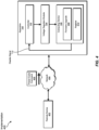
- FIG. 4 illustrates an example implementation 400 of apparatus 100 in which apparatus 100 is communicatively coupled to a remote device 402 via a network 404.
- remote device 402 may transmit and/or send a power-cycle command 406 to apparatus 100 via network 404.
- power-cycle command 406 may be transmitted and/or sent to apparatus 100 in connection with a firmware upgrade 408 installed to computing device 106.
- an administrator operating remote device 402 may direct and/or cause remote device 402 to transmit and/or send power-cycle command 406 to apparatus 100 in connection with firmware upgrade 408 or as a stand-alone instruction or operation.
- power-cycle command 406 may direct computing device 106 to write data to a register 410.
- writing this data to register 410 may cause computing device 106 to issue disable signal 110.
- writing this data to register 410 may trigger the issuance of disable signal 110.
- disable signal 110 may cause controller 102 to suspend the passage of electric power to voltage regulator module 104 to facilitate power-cycling computing device 106.
- power-cycling computing device 106 in this way may enable computing device 106 to implement and/or complete firmware upgrade 408.
- network 404 may include and/or represent any medium and/or architecture capable of facilitating communication and/or data transfer between remote device 402 and apparatus 100.
- network 204 may include remote device 402 and/or apparatus 100 even though remote device 402 and apparatus 100 are illustrated as being external to network 404 in FIG. 4 .
- network 404 may include other devices that facilitate communication between remote device 402 and/or apparatus 100.
- Network 404 may facilitate communication or data transfer using wireless and/or wired connections.
- Examples of network 404 include, without limitation, an intranet, an access network, a layer 2 network, a layer 3 network, a multiprotocol label switching (MPLS) network, an Internet protocol (IP) network, a heterogeneous network (e.g., layer 2, layer 3, IP, and/or MPLS) network, a Wide Area Network (WAN), a Local Area Network (LAN), a Personal Area Network (PAN), the Internet, Power Line Communications (PLC), a cellular network (e.g., a Global System for Mobile Communications (GSM) network), portions of one or more of the same, variations or combinations of one or more of the same, and/or any other suitable network.
- MPLS multiprotocol label switching
- IP Internet protocol
- IP Internet protocol
- LAN Local Area Network
- PAN Personal Area Network
- PLC Power Line Communications
- GSM Global System for Mobile Communications
- remote device 402 may include and/or represent any type or form of physical computing device capable of reading computer-executable instructions, handling network traffic, and/or sending power-cycle commands.
- Examples of remote device 402 include, without limitation, routers (such as a transit label switching router, a label edge router, a provider edge router, a hub router, a spoke router, an autonomous system boundary router, and/or an area border router), switches, hubs, modems, bridges, repeaters, gateways (such as broadband network gateways (BNGs)), multiplexers, network adapters, network interfaces, linecards, collectors, client devices, laptops, tablets, desktops, servers, cellular phones, personal digital assistants (PDAs), multimedia players, embedded systems, wearable devices, gaming consoles, portions of one or more of the same, variations or combinations of one or more of the same, and/or any other suitable devices.
- routers such as a transit label switching router, a label edge router, a provider edge router, a hub router, a spoke router,
- FIG. 5 is a flow diagram of an example method 500 for assembling and/or manufacturing an apparatus for power-cycling field-replaceable units remotely.
- Method 500 may include the step of electrically coupling a controller to a voltage regulator module configured to convert electric power supplied by a power source into at least one regulated voltage (510).
- Step 510 may be performed in a variety of ways, including any of those described above in connection with FIGS. 1-4 .
- a computing equipment manufacturer or subcontractor electrically couple a hot swap controller to a voltage regulator module configured to convert and/or transform electric power supplied by a power source into at least one regulated voltage.
- Method 500 may also include the step of electrically coupling the power source to the controller to enable the controller to control passage of the electric power from the power source to the voltage regulator module (520).
- Step 520 may be performed in a variety of ways, including any of those described above in connection with FIGS. 1-4 .
- a computing equipment manufacturer or subcontractor may electrically couple one or more PSMs to the hot swap controller to enable the hot swap controller to control passage of the electric power from the power source to the voltage regulator module.
- Method 500 may further include the step of electrically coupling the voltage regulator module to a computing device to facilitate powering the computing device via the regulated voltage (530).
- Step 530 may be performed in a variety of ways, including any of those described above in connection with FIGS. 1-4 .
- a computing equipment manufacturer or subcontractor may electrically couple the voltage regulator module to a CPLD to facilitate powering the CPLD via the regulated voltage.
- Method 500 may additionally include the step of communicatively coupling the computing device to the controller to enable the computing device to provide a disable signal that causes the controller to suspend passage of the electric power to the voltage regulator module (540).
- Step 540 may be performed in a variety of ways, including any of those described above in connection with FIGS. 1-4 .
- a computing equipment manufacturer or subcontractor may communicatively couple the CPLD to the hot swap controller to enable the CPLD to provide a disable signal that causes the hot swap controller to suspend passage of the electric power to the voltage regulator module.
- the hot swap controller, the voltage regulator module, and/or the CPLD may be incorporated and/or packaged as part of a routing engine for a router.
- an apparatus which may include (1) a voltage regulator module configured to convert electric power into at least one regulated voltage, (2) a controller configured to control passage of the electric power to the voltage regulator module, and (3) a computing device configured to (A) be powered by the regulated voltage and (B) provide a disable signal that causes the controller to suspend passage of the electric power to the voltage regulator module.
- a voltage regulator module configured to convert electric power into at least one regulated voltage
- a controller configured to control passage of the electric power to the voltage regulator module
- a computing device configured to (A) be powered by the regulated voltage and (B) provide a disable signal that causes the controller to suspend passage of the electric power to the voltage regulator module.
Landscapes
- Engineering & Computer Science (AREA)
- Theoretical Computer Science (AREA)
- Power Engineering (AREA)
- Physics & Mathematics (AREA)
- General Engineering & Computer Science (AREA)
- General Physics & Mathematics (AREA)
- Computer Hardware Design (AREA)
- Computing Systems (AREA)
- Electromagnetism (AREA)
- Radar, Positioning & Navigation (AREA)
- Automation & Control Theory (AREA)
- Power Sources (AREA)
Abstract
Description
- Power-cycling may have various purposes and/or benefits. For example, to complete certain firmware upgrades on conventional field-replaceable units, administrators may need to power-cycle the conventional field-replaceable units. Unfortunately, such power-cycling may require the administrators to be physically present at the location of the conventional field-replaceable units to turn off and/or disconnect the input power from the conventional field-replaceable units and then turn back on and/or reconnect the input power to the conventional field-replaceable units.
- As a specific example, a conventional field-replaceable unit may be unable to restore its own input power without the physical presence of an administrator because the conventional field-replaceable unit is nonoperational while the power is turned off and/or disconnected. The instant disclosure, therefore, identifies and addresses a need for additional and improved apparatuses, systems, and methods for power-cycling field-replaceable units remotely.
- The invention is defined by the appended independent claims. As will be described in greater detail below, the instant disclosure generally relates to apparatuses, systems, and methods for power-cycling field-replaceable units remotely. In one example, an apparatus for accomplishing such a task may include (1) a voltage regulator module configured to convert electric power into at least one regulated voltage, (2) a controller configured to control passage of the electric power to the voltage regulator module, and (3) a computing device configured to (A) be powered by the regulated voltage and (B) provide a disable signal that causes the controller to suspend passage of the electric power to the voltage regulator module.
- Similarly, a system for accomplishing such a task may include (1) at least one power source and (2) at least one field-replaceable unit electrically coupled to the power source, wherein the field-replaceable unit comprises (A) a voltage regulator module configured to convert electric power provided by the power source into at least one regulated voltage, (B) a controller configured to control passage of the electric power to the voltage regulator module, and a computing device configured to (I) be powered by the regulated voltage and (II) provide a disable signal that causes the controller to suspend passage of the electric power to the voltage regulator module.
- A corresponding method may include (1) electrically coupling a controller to a voltage regulator module configured to convert electric power supplied by a power source into at least one regulated voltage, (2) electrically coupling the power source to the controller to enable the controller to control passage of the electric power from the power source to the voltage regulator module, (3) electrically coupling the voltage regulator module to a computing device to facilitate powering the computing device via the regulated voltage, and (4) communicatively coupling the computing device to the controller to enable the computing device to provide a disable signal that causes the controller to suspend passage of the electric power to the voltage regulator module.
- Features from any of the above-mentioned embodiments may be used in combination with one another in accordance with the general principles described herein. These and other embodiments, features, and advantages will be more fully understood upon reading the following detailed description in conjunction with the accompanying drawings and claims.
- The accompanying drawings illustrate a number of example embodiments and are a part of the specification. Together with the following description, these drawings demonstrate and explain various principles of the instant disclosure.
-
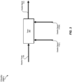
FIG. 1 is an illustration of an example apparatus for power-cycling field-replaceable units remotely in accordance with one or more embodiments of this disclosure. -
FIG. 2 is an illustration of an example system for power-cycling field-replaceable units remotely in accordance with one or more embodiments of this disclosure. -
FIG. 3 is an illustration of an example circuitry that facilitates power-cycling field-replaceable units remotely in accordance with one or more embodiments of this disclosure. -
FIG. 4 is an illustration of an example implementation of an apparatus for power-cycling field-replaceable units remotely in accordance with one or more embodiments of this disclosure. -
FIG. 5 is a flow diagram of an example method for power-cycling field-replaceable units remotely in accordance with one or more embodiments of this disclosure. - Throughout the drawings, identical reference characters and descriptions indicate similar, but not necessarily identical, elements. While the example embodiments described herein are susceptible to various modifications and alternative forms, specific embodiments have been shown by way of example in the drawings and will be described in detail herein. However, the example embodiments described herein are not intended to be limited to the particular forms disclosed. Rather, the instant disclosure covers all modifications, equivalents, and alternatives falling within the scope of the appended claims.
- The present disclosure describes various apparatuses, systems, and methods for power-cycling field-replaceable units remotely. As will be explained in greater detail below, embodiments of the instant disclosure may include and/or involve one or more features and/or components of a field-replaceable unit that facilitate toggling the input power to the field-replaceable unit. For example, a field-replaceable unit (such as a routing engine) may include and/or represent onboard circuitry and/or logic that directs a power controller to suspend passage of electric power and then restore passage of electric power after a certain amount of time. In this example, the onboard circuitry and/or logic may enable the field-replaceable unit to perform and/or execute remote power cycles to complete firmware upgrades on one or more devices, components, and/or features of the field-replaceable unit.
- As a specific example, rather than being physically present at the location of a field-replaceable unit, an administrator may be able to transmit and/or send a software-based command that initiates a power cycle of the field-replaceable unit from a remote computing device. By doing so, the administrator may be able to manage and/or oversee firmware upgrades on a wider range of field-replaceable units, including those installed in network devices (e.g., routers) at remote locations. Additionally or alternatively, the administrator may be able to manage and/or oversee firmware upgrades on field-replaceable units located in faraway places, which would otherwise be impractical and/or infeasible. The administrator may also implement a remote power cycle on a field-replaceable unit that has frozen and/or is potentially malfunctioning for one reason or another. This remote power-cycling feature and/or option may help service providers save money and/or time in the administration of their devices across various locations.
- In some examples, the term "power cycle" and/or the phrase "power-cycling" may refer to the process and/or act of cutting off or preventing the passage of electric power to some or all components on a power-consuming device (such as a field-replaceable unit) and subsequently restoring the passage of electric power to such components. In such examples, the term "power cycle" and/or the phrase "power-cycling" may be distinguished and/or contrasted from the term "reboot" and/or the phrase "rebooting", respectively. For example, the term "reboot" and/or the phrase "rebooting" may refer to the process and/or act of restarting some or all components on a power-consuming device while such components remain powered up and/or without necessarily cutting off or preventing the passage of electric power to such components.
- The following will provide, with reference to
FIGS. 1-4 , detailed descriptions of example components, apparatuses, systems, configurations, and/or implementations for power-cycling field-replaceable units remotely. In addition, the discussion corresponding toFIG. 5 will provide detailed descriptions of an example method for assembling and/or manufacturing apparatuses for power-cycling field-replaceable units remotely. -
FIG. 1 illustrates anexample apparatus 100 for power-cycling field-replaceable units remotely. In some examples,example apparatus 100 may include and/or represent various features, components, and/or devices that make up and/or form part of a field-replaceable unit. For example,apparatus 100 may include and/or represent acontroller 102, avoltage regulator module 104, and/or acomputing device 106. In this example,controller 102 may be configured to control passage ofelectric power 108 from a power source (not necessarily illustrated inFIG. 1 ) tovoltage regulator module 104. - In some examples,
voltage regulator module 104 may be configured to convertelectric power 108 into regulated voltages 112(1)-(N). In these examples, regulated voltages 112(1)-(N) may include and/or represent power or voltage buses of differing voltage levels (e.g., 3.3 volts, 5 volts, 12 volts, etc.). In one example,computing device 106 may be configured to be powered by regulated voltage 112(1). Additionally or alternatively,computing device 106 may generate, issue, and/or provide adisable signal 110 that causescontroller 102 to suspend passage ofelectric power 108 tovoltage regulator module 104. - In some examples,
controller 102 may be electrically coupled between the power source andvoltage regulator module 104. In one example,voltage regulator module 104 may be electrically coupled betweencontroller 102 andcomputing device 106 and/or any number of additional computing devices powered by one or more of regulated voltages 112(1)-(N). Additionally or alternatively,computing device 106 may be electrically coupled tovoltage regulator module 104, and/orcomputing device 106 may be communicatively coupled tocontroller 102 to facilitate the transmission of adisable signal 110 betweencomputing device 106 andcontroller 102. - Upon suspension of the passage of
electric power 108 atcontroller 102,voltage regulator module 104 may be temporarily unable to convertelectric power 108 into regulated voltages 112(1)-(N). As a result, the levels of regulated voltages 112(1)-(N) may decrease and/or decline to zero volts for a certain amount of time. This decrease and/or decline of the levels of regulated voltages 112(1) may causecomputing device 106 and/or any other electrical devices and/or components powered by one or more of regulated voltages 112(1)-(N) to completely shut and/or power down. - In some examples, once the necessary amount of time has expired and/or passed,
controller 102 may restore and/or revive the passage ofelectric power 108 tovoltage regulator module 104. Upon restoration of the passage ofelectric power 108 atcontroller 102,voltage regulator module 104 may again be able to convertelectric power 108 into regulated voltages 112(1)-(N). As a result, regulated voltages 112(1)-(N) may increase and/or return to their previous, default, and/or original levels. This increase and/or return of the levels of regulated voltages 112(1) may cause and/or enablecomputing device 106 and/or any other electrical devices and/or components configured to draw power from one or more of regulated voltages 112(1)-(N) to power up and/or restore functionality or operability. - In some examples, such toggling (e.g., turning off and on) of
electric power 108 atcontroller 102 may constitute, represent, and/or effectuate a power cycle ofcomputing device 106 and/or any other electrical devices and/or components configured to be powered by one or more of regulated voltages 112(1)-(N). In such examples, this power-cycling may enablecomputing device 106 and/or any other electrical devices and/or components configured to be powered by one or more of regulated voltages 112(1)-(N) to complete and/or finalize a firmware upgrade without the need for on-site human interaction and/or intervention. - For example,
computing device 106 may receive and/or install a firmware upgrade that necessitates a power cycle. In one example, the firmware upgrade may cause and/or triggercomputing device 106 to generate, issue, and/or providedisable signal 110. In this example,computing device 106 may include and/or represent a complex programmable logic device (CPLD) and/or a field-programmable gate array (FPGA). Additionally or alternatively,controller 102 may include and/or represent a hot swap controller. - In some examples,
computing device 106 may receive and/or detect a power-cycle command transmitted by a remote device (not necessarily illustrated inFIG. 1 ). In one example, the power-cycle command may cause and/orprompt computing device 106 to write certain data to a register. In this example, the data written to the register may cause and/or trigger the generation and/or issuance of disablesignal 110. Disablesignal 110 may cause and/orprompt controller 102 to toggleelectric power 108 and/or cut offelectric power 108 as part of a power cycle. - In some examples,
apparatus 100 may include and/or represent one or more additional components, devices, features, and/or mechanisms that are not necessarily illustrated and/or labeled inFIG. 1 . For example,apparatus 100 may also include and/or represent additional analog and/or digital circuitry, onboard logic, transistors, resistors, capacitors, diodes, inductors, switches, registers, flipflops, connections, traces, buses, semiconductor (e.g., silicon) devices and/or structures, storage devices, circuit boards, housings, combinations or variations of one or more of the same, and/or any other suitable components that facilitate power-cycling field-replaceable units remotely. - As a specific example, additional circuitry and/or onboard logic may reside and/or be applied or configured between
computing device 106 and/orcontroller 102. In this example, the additional circuitry and/or onboard logic may be configured to drawelectric power 108 directly from the power source. Additionally or alternatively, the additional circuitry and/or onboard logic may pass and/or forward disablesignal 110 tocontroller 102 directly or indirectly. For example, disablesignal 110 may cause and/or prompt the additional circuitry and/or onboard logic to disable and/or deactivatecontroller 102 via an electrical signal or response. In this example, the additional circuitry and/or onboard logic may also be configured to re-enable and/or reactivatecontroller 102 via an electrical signal or response after a certain amount of time has passed since disabling and/or deactivatingcontroller 102. - In some examples, the additional circuitry and/or onboard logic may include and/or represent a delay circuit or a timer. In one example, the delay circuit and/or timer may be tuned to convert and/or transform disable
signal 110 to an enable signal upon expiration of a certain amount of time. In this example, the certain amount of time may be sufficient to ensure thatcomputing device 106 and/or any other relevant devices have fully powered down prior to the transformation of disablesignal 110 into the enable signal. As a result, the delay circuit and/or timer may effectively power-cycle computing device 106 and/or any other relevant devices powered by regulated voltages 112(1)-(N). In other words, the transformation of disablesignal 110 into the enable signal may causecontroller 102 to restore the passage ofelectric power 108 tovoltage regulator module 104, thereby completing a power cycle ofcomputing device 106 and/or any other relevant devices powered by regulated voltages 112(1)-(N). - In one example, a delay circuit configured between
computing device 106 andcontroller 102 may effectively delay the transformation of disablesignal 110 back into the enable signal for a certain amount of time. Additionally or alternatively, a timer configured betweencomputing device 106 andcontroller 102 may effectively track the amount of time disablesignal 110 is maintained and/or held. In this example, once that amount of time reaches a certain threshold, the timer may cause circuitry betweencomputing device 106 andcontroller 102 to transform and/or convert disablesignal 110 to the enable signal. - In some examples,
voltage regulator module 104 may be unable to convertelectric power 108 into regulated voltages 112(1)-(N) while the passage ofelectric power 108 is suspended bycontroller 102. In such examples,voltage regulator module 104 may cease and/or stop such power conversion during the suspension. As a result,computing device 106 may be forced to power down due at least in part tovoltage regulator module 104 ceasing such power conversion. -
FIG. 2 illustrates anexample system 200 for power-cycling field-replaceable units remotely. As illustrated inFIG. 2 ,example system 200 may include and/or represent field-replaceable units 202(1)-(N) and power supply modules (PSMs) 214(1)-(N). In some examples, field-replaceable units 202(1)-(N) may be electrically coupled to PSMs 214(1)-(N). In such examples, PSMs 214(1)-(N) may supply and/or provideelectric power 108 to field-replaceable units 202(1)-(N). - In some examples, field-replaceable unit 202(1) may include and/or represent a controller 102(1) electrically coupled between PSMs 214(1)-(N) and a voltage regulator module 104(1). In such examples, voltage regulator module 104(1) may be electrically coupled between controller 102(1) and a computing device 106(1) and/or any number of additional computing devices powered by one or more of regulated voltages 112(1)-(N). In one example, computing device 106(1) may be electrically coupled to voltage regulator module 104(1) via regulated voltage 112(1), and/or computing device 106(1) may be communicatively coupled to controller 102(1) via circuitry 208(1) that facilitates the transmission of a disable signal 110(1) between computing device 106(1) and controller 102(1). In this example, circuitry 208(1) may delay the transformation of disable signal 110(1) back into an enable signal for a certain amount of time.
- Similarly, field-replaceable unit 202(N) may include and/or represent a controller 102(N) electrically coupled between PSMs 214(1)-(N) and a voltage regulator module 104(N). In such examples, voltage regulator module 104(N) may be electrically coupled between controller 102(N) and a computing device 106(N) and/or any number of additional computing devices powered by one or more of regulated voltages 212(1)-(N). In one example, computing device 106(N) may be electrically coupled to voltage regulator module 104(N) via regulated voltage 212(1), and/or computing device 106(N) may be communicatively coupled to controller 102(N) via circuitry 208(N) that facilitates the transmission of a disable signal 110(N) between computing device 106(N) and controller 102(N). In this example, circuitry 208(N) may delay the transformation of disable signal 110(N) back into an enable signal for a certain amount of time.
- In some examples, computing device 106(1) may also be communicatively coupled to controller 102(N) via circuitry 208(N), which facilitates the transmission of a disable signal 210(1) between computing device 106(1) and controller 102(N). In such examples, circuitry 208(N) may delay the transformation of disable signal 210(1) back into an enable signal for a certain amount of time. In one example, disable signal 210(1) may cause controller 102(N) to suspend the passage of
electric power 108 to voltage regulator module 104(N). Accordingly, computing device 106(1) may be able to power-cycle all or a portion of field-replaceable unit 202(N) (e.g., computing device 106(N)) if field-replaceable unit 202(N) gets stuck in a certain condition and/or experiences a potential failure. - In some examples, computing device 106(N) may also be communicatively coupled to controller 102(1) via circuitry 208(1), which facilitates the transmission of a disable signal 210(N) between computing device 106(N) and controller 102(1). In such examples, circuitry 208(1) may delay the transformation of disable signal 210(N) back into an enable signal for a certain amount of time. In one example, disable signal 210(N) may cause controller 102(1) to suspend the passage of
electric power 108 to voltage regulator module 104(1). Accordingly, computing device 106(N) may be able to power-cycle all or a portion of field-replaceable unit 202(1) (e.g., computing device 106(1)) if field-replaceable unit 202(1) gets stuck in a certain condition and/or experiences a potential failure. - In some examples, computing device 106(1) may be configured to detect a potential failure (e.g., an unresponsive state, an error, an exception, etc.) experienced by field-replaceable unit 202(N). In response to detecting the potential failure, computing device 106(1) may issue and/or provide disable signal 210(1) to controller 102(N) via circuitry 208(N). In such examples, disable signal 210(1) may support, effectuate, and/or facilitate power-cycling all or a portion of field-replaceable unit 202(N). For example, disable signal 210(1) may cause field-replaceable unit 202(N) to power-cycle an onboard CPLD and/or FPGA whose firmware is undergoing an upgrade.
- Similarly, computing device 106(N) may be configured to detect a potential failure experienced by field-replaceable unit 202(1). In response to detecting the potential failure, computing device 106(N) may issue and/or provide disable signal 210(N) to controller 102(1) via circuitry 208(1). In such examples, disable signal 210(N) may support, effectuate, and/or facilitate power-cycling all or a portion of field-replaceable unit 202(1). For example, disable signal 210(N) may cause field-replaceable unit 202(1) to power-cycle an onboard CPLD and/or FPGA whose firmware is undergoing an upgrade.
- In some examples, field-replaceable units 202(1)-(N) may generally refer to and/or represent any type or form of modular and/or removable device or component that facilitates and/or contributes to the flow of traffic within a network and/or across multiple networks. Examples of field-replaceable units 202(1)-(N) include, without limitation, routing engines, physical interface cards (PICs), flexible PIC concentrators (FPCs), switch interface boards (SIBs), control boards, routing engines, communication ports, fan trays, connector interface panels, portions of one or more of the same, combinations or variations of one or more of the same, and/or any other suitable field-replaceable units.
- In some examples, circuitry 208(1) and/or 208(N) may include and/or represent any type or form of circuit, configuration, and/or device that forces a specific response and/or signal after a certain amount of delay. For example, circuitry 208(1) may pass and/or forward disable signal 110(1)-or a corresponding response or signal-to controller 102(1) to suspend the passage of
electric power 108 for a certain amount of time. In this example, after having passed and/or forwarded disable signal 110(1) to controller 102(1), computing device 106(1) may power down, and circuitry 208(1) may force an enable signal to reach controller 102(1) after a certain amount of delay. By doing so, circuitry 208(1) may be able to toggleelectric power 108 and/or ensure that computing device 106(1) is power-cycled, as computing device 106(1) cannot re-enable controller 102(1) alone due at least in part to being powered down. -
FIG. 3 illustrates an example implementation of circuitry 208(1) that forces disable signal 210(1) and/or disable signal 210(N) to be converted and/or transformed into an enablesignal 310 after a tunable delay. As illustrated inFIG. 3 , example circuitry 208(1) may include and/or represent atimer 302 powered byelectric power 108. In some examples,timer 302 may remain powered up and/or on while controller 102(1) suspends the passage ofelectric power 108 to voltage regulator module 104(1). As a result,timer 302 may output and/or provide enable signal 310 to controller 102(1) after disable signal 110(1) or 210(N) caused controller 102(1) to suspend the passage ofelectric power 108 to voltage regulator module 104(1). In such examples, enablesignal 310 may follow disable signal 110(1) or 210(N) after a certain amount of delay has transpired. In one example, the delay may constitute and/or represent enough time to fully power downcomputing device 106 and/or any number of additional components powered by one or more of regulated voltages 112(1)-(N). - In some examples,
timer 302 may include and/or represent any type or form of device, component, and/or circuitry capable of producing an enable signal after a certain delay following a disable signal.Timer 302 may include and/or represent analog and/or digital circuitry, onboard logic, transistors, resistors, capacitors, diodes, inductors, switches, registers, flipflops, connections, traces, buses, semiconductor (e.g., silicon) devices and/or structures, storage devices, circuit boards, combinations or variations of one or more of the same, and/or any other suitable components that facilitate producing a delayed enable signal after a disable signal. - As a specific example, computing device 106(1) and/or circuitry 208(1) may be configured to provide and/or produce enable signal 310 as a default state, thereby causing controller 102(1) to support and/or facilitate the passage of
electric power 108 to voltage regulator module 104(1) as a default state. In one example, computing device 106(1) may provide and/or produce disable signal 110(1) as part of and/or in conjunction with a firmware upgrade. In this example, circuitry 208(1) may carry and/or pass disable signal 110(1) to controller 102(1) to suspend the passage ofelectric power 108 until being subsequently re-enabled. Computing device 106(1) may be powered down during and as a result of this suspension. - Continuing with this example, circuitry 208(1) may be configured to maintain and/or hold disable signal 110(1) for a tunable amount of time (e.g., 1 second, 5 seconds, 10 seconds, 60 seconds, etc.). The amount of time may be tuned to ensure that onboard components in need of a power cycle are able to fully power down. After completion and/or expiration of that amount of time, circuitry 208(1) may restore enable
signal 310 to re-enable controller 102(1) for the passage ofelectric power 108 even though computing device 106(1) is still powered down. The restoration of enable signal 310 may cause controller 102(1) to return and/or restore the passage ofelectric power 108 to voltage regulator module 104(1), thereby completing a power cycle of computing device 106(1) and/or any other components powered by one or more of regulated voltages 112(1)-(N). - In some examples, a disable signal may be represented and/or provided as a digital zero and/or a low-logic value or level. In such examples, an enable signal may be represented and/or provided as a digital one and/or a high-logic value or level. In alternative examples, a disable signal may be represented and/or provided as a digital one and/or a high-logic value or level. In such examples, an enable signal may be represented and/or provided as a digital zero and/or a low-logic value or level. In one example, the configuration of circuitry 208(1) may control and/or dictate whether the disable signal or the enable signal is a digital zero or a digital one.
-
FIG. 4 illustrates anexample implementation 400 ofapparatus 100 in whichapparatus 100 is communicatively coupled to aremote device 402 via anetwork 404. As illustrated inFIG. 4 ,remote device 402 may transmit and/or send a power-cycle command 406 toapparatus 100 vianetwork 404. In some examples, power-cycle command 406 may be transmitted and/or sent toapparatus 100 in connection with afirmware upgrade 408 installed tocomputing device 106. In other examples, an administrator operatingremote device 402 may direct and/or causeremote device 402 to transmit and/or send power-cycle command 406 toapparatus 100 in connection withfirmware upgrade 408 or as a stand-alone instruction or operation. - In some examples, power-
cycle command 406 may directcomputing device 106 to write data to aregister 410. In such examples, writing this data to register 410 may causecomputing device 106 to issue disablesignal 110. In other words, writing this data to register 410 may trigger the issuance of disablesignal 110. In one example, disablesignal 110 may causecontroller 102 to suspend the passage of electric power tovoltage regulator module 104 to facilitate power-cycling computing device 106. In this example, power-cycling computing device 106 in this way may enablecomputing device 106 to implement and/orcomplete firmware upgrade 408. - In some examples,
network 404 may include and/or represent any medium and/or architecture capable of facilitating communication and/or data transfer betweenremote device 402 andapparatus 100. In one example, network 204 may includeremote device 402 and/orapparatus 100 even thoughremote device 402 andapparatus 100 are illustrated as being external tonetwork 404 inFIG. 4 . Additionally or alternatively,network 404 may include other devices that facilitate communication betweenremote device 402 and/orapparatus 100.Network 404 may facilitate communication or data transfer using wireless and/or wired connections. Examples ofnetwork 404 include, without limitation, an intranet, an access network, a layer 2 network, a layer 3 network, a multiprotocol label switching (MPLS) network, an Internet protocol (IP) network, a heterogeneous network (e.g., layer 2, layer 3, IP, and/or MPLS) network, a Wide Area Network (WAN), a Local Area Network (LAN), a Personal Area Network (PAN), the Internet, Power Line Communications (PLC), a cellular network (e.g., a Global System for Mobile Communications (GSM) network), portions of one or more of the same, variations or combinations of one or more of the same, and/or any other suitable network. - In some examples,
remote device 402 may include and/or represent any type or form of physical computing device capable of reading computer-executable instructions, handling network traffic, and/or sending power-cycle commands. Examples ofremote device 402 include, without limitation, routers (such as a transit label switching router, a label edge router, a provider edge router, a hub router, a spoke router, an autonomous system boundary router, and/or an area border router), switches, hubs, modems, bridges, repeaters, gateways (such as broadband network gateways (BNGs)), multiplexers, network adapters, network interfaces, linecards, collectors, client devices, laptops, tablets, desktops, servers, cellular phones, personal digital assistants (PDAs), multimedia players, embedded systems, wearable devices, gaming consoles, portions of one or more of the same, variations or combinations of one or more of the same, and/or any other suitable devices. -
FIG. 5 is a flow diagram of an example method 500 for assembling and/or manufacturing an apparatus for power-cycling field-replaceable units remotely. Method 500 may include the step of electrically coupling a controller to a voltage regulator module configured to convert electric power supplied by a power source into at least one regulated voltage (510). Step 510 may be performed in a variety of ways, including any of those described above in connection withFIGS. 1-4 . For example, a computing equipment manufacturer or subcontractor electrically couple a hot swap controller to a voltage regulator module configured to convert and/or transform electric power supplied by a power source into at least one regulated voltage. - Method 500 may also include the step of electrically coupling the power source to the controller to enable the controller to control passage of the electric power from the power source to the voltage regulator module (520). Step 520 may be performed in a variety of ways, including any of those described above in connection with
FIGS. 1-4 . For example, a computing equipment manufacturer or subcontractor may electrically couple one or more PSMs to the hot swap controller to enable the hot swap controller to control passage of the electric power from the power source to the voltage regulator module. - Method 500 may further include the step of electrically coupling the voltage regulator module to a computing device to facilitate powering the computing device via the regulated voltage (530). Step 530 may be performed in a variety of ways, including any of those described above in connection with
FIGS. 1-4 . For example, a computing equipment manufacturer or subcontractor may electrically couple the voltage regulator module to a CPLD to facilitate powering the CPLD via the regulated voltage. - Method 500 may additionally include the step of communicatively coupling the computing device to the controller to enable the computing device to provide a disable signal that causes the controller to suspend passage of the electric power to the voltage regulator module (540). Step 540 may be performed in a variety of ways, including any of those described above in connection with
FIGS. 1-4 . For example, a computing equipment manufacturer or subcontractor may communicatively couple the CPLD to the hot swap controller to enable the CPLD to provide a disable signal that causes the hot swap controller to suspend passage of the electric power to the voltage regulator module. In one example, the hot swap controller, the voltage regulator module, and/or the CPLD may be incorporated and/or packaged as part of a routing engine for a router. - Thus, from one perspective, there has now been described an apparatus which may include (1) a voltage regulator module configured to convert electric power into at least one regulated voltage, (2) a controller configured to control passage of the electric power to the voltage regulator module, and (3) a computing device configured to (A) be powered by the regulated voltage and (B) provide a disable signal that causes the controller to suspend passage of the electric power to the voltage regulator module. Various other apparatuses, systems, and methods are also disclosed.
- While the foregoing disclosure sets forth various embodiments using specific block diagrams, flowcharts, and examples, each block diagram component, flowchart step, operation, and/or component described and/or illustrated herein may be implemented, individually and/or collectively, using a wide range of hardware, software, or firmware (or any combination thereof) configurations. In addition, any disclosure of components contained within other components should be considered merely an example since many other architectures can be implemented to achieve the same functionality.
- The process parameters and sequence of the steps described and/or illustrated herein are given by way of example only and can be varied as desired. For example, while the steps illustrated and/or described herein may be shown or discussed in a particular order, these steps do not necessarily need to be performed in the order illustrated or discussed. The various example methods described and/or illustrated herein may also omit one or more of the steps described or illustrated herein or include additional steps in addition to those disclosed.
- The preceding description has been provided to enable others skilled in the art to best utilize various aspects of the example embodiments disclosed herein. This description is not intended to be exhaustive or to be limited to any precise form disclosed. Many modifications and variations are possible without departing from the scope of the instant disclosure. The embodiments disclosed herein should be considered in all respects illustrative and not restrictive. Reference should be made to the appended claims and their equivalents in determining the scope of the instant disclosure.
- Unless otherwise noted, the terms "connected to" and "coupled to" (and their derivatives), as used in the specification and claims, are to be construed as permitting both direct and indirect (i.e., via other elements or components) connection. In addition, the terms "a" or "an," as used in the specification and claims, are to be construed as meaning "at least one of." Finally, for ease of use, the terms "including" and "having" (and their derivatives), as used in the specification and claims, are interchangeable with and have the same meaning as the word "comprising."
- Further examples of feature combinations taught by the present disclosure are set out in the following numbered clauses:
- 1. An apparatus comprising:
- a voltage regulator module configured to convert electric power into at least one regulated voltage;
- a controller configured to control passage of the electric power to the voltage regulator module; and
- a computing device configured to:
- be powered by the regulated voltage; and
- provide a disable signal that causes the controller to suspend passage of the electric power to the voltage regulator module.
- 2. The apparatus of
clause 1, wherein the computing device is further configured to:- receive a power-cycle command transmitted by a remote device; and
- issue the disable signal in response to the power-cycle command.
- 3. The apparatus of clause 2, wherein the power-cycle command causes the computing device to write data to a register that triggers the issuance of the disable signal.
- 4. The apparatus of clause 2 or clause 3, wherein the computing device is configured to install a firmware upgrade that necessitates a power cycle prior to issuing the disable signal.
- 5. The apparatus of any preceding clause, wherein the controller is further configured to:
- suspend passage of the electric power to the voltage regulator module in response to the disable signal; and
- maintain the suspension of the electric power until the disable signal transforms into an enable signal.
- 6. The apparatus of clause 5, wherein the controller is further configured to restore passage of the electric power to the voltage regulator module upon transformation of the disable signal to the enable signal to complete a power cycle of at least one power-consuming device.
- 7. The apparatus of clause 6, further comprising circuitry that delays the transformation of the disable signal to the enable signal for a certain amount of time.
- 8. The apparatus of clause 7, further comprising a timer configured to track the certain amount of time and cause the controller to restore passage of the electric power upon expiration of the certain amount of time.
- 9. The apparatus of any of clauses 6-8, wherein the power-consuming device comprises at least one of:
- the computing device;
- a field-replaceable unit that incorporates the voltage regulator module, the controller, and the computing device; or
- a field-replaceable unit remote from the computing device.
- 10. The apparatus of any preceding clause, wherein:
- the voltage regulator module is further configured to cease converting the electric power into the regulated voltage while passage of the electric power is suspended by the controller; and
- the computing device is further configured to power down due at least in part to the voltage regulator module ceasing conversion of the electric power into the regulated voltage.
- 11. The apparatus of any preceding clause, further comprising:
- a field-replaceable unit that incorporates the voltage regulator module, the controller, and the computing device; and
- an additional field-replaceable unit comprising:
- an additional voltage regulator module configured to convert the electric power into at least one additional regulated voltage;
- an additional controller configured to control passage of the electric power to the additional voltage regulator module; and
- an additional computing device configured to:
- be powered by the additional regulated voltage; and
- provide an additional disable signal that causes the additional controller to suspend passage of the electric power to the additional voltage regulator module.
- 12. The apparatus of clause 11, wherein:
- the computing device is further configured to provide the additional disable signal that causes the additional controller to suspend passage of the electric power to the additional voltage regulator module; and
- the additional computing device is further configured to provide an alternative disable signal that causes the controller to suspend passage of the electric power to the voltage regulator module.
- 13. The apparatus of clause 11 or clause 12, wherein the computing device is further configured to:
- detect a potential failure experienced by the additional field-replaceable unit; and
- in response to detecting the potential failure, issues the additional disable signal to power cycle the additional field-replaceable unit.
- 14. The apparatus of any preceding clause, wherein the computing device comprises at least one of:
- a complex programmable logic device; or
- a field-programmable gate array.
- 15. A system comprising:
- at least one power source; and
- at least one field-replaceable unit electrically coupled to the power source, wherein the field-replaceable unit comprises:
- a voltage regulator module configured to convert electric power provided by the power source into at least one regulated voltage;
- a controller configured to control passage of the electric power to the voltage regulator module; and
- a computing device configured to:
- be powered by the regulated voltage; and
- provide a disable signal that causes the controller to suspend passage of the electric power to the voltage regulator module.
- 16. The system of clause 15, wherein the computing device is further configured to:
- receive a power-cycle command transmitted by a remote device; and
- issue the disable signal in response to the power-cycle command.
- 17. The system of clause 16, wherein the power-cycle command causes the computing device to write data to a register that triggers the issuance of the disable signal.
- 18. The system of clause 16 or clause 17, wherein the computing device is configured to install a firmware upgrade that necessitates a power cycle prior to issuing the disable signal.
- 19. The system of any of clauses 15-18, wherein the controller is further configured to:
- suspend passage of the electric power to the voltage regulator module in response to the disable signal; and
- maintain the suspension of the electric power until the disable signal transforms into an enable signal.
- 20. A method comprising:
- electrically coupling a controller to a voltage regulator module configured to convert electric power supplied by a power source into at least one regulated voltage;
- electrically coupling the power source to the controller to enable the controller to control passage of the electric power from the power source to the voltage regulator module;
- electrically coupling the voltage regulator module to a computing device to facilitate powering the computing device via the regulated voltage; and
- communicatively coupling the computing device to the controller to enable the computing device to provide a disable signal that causes the controller to suspend passage of the electric power to the voltage regulator module.
Claims (15)
- An apparatus comprising:a voltage regulator module configured to convert electric power into at least one regulated voltage;a controller configured to control passage of the electric power to the voltage regulator module; anda computing device configured to:be powered by the regulated voltage; andprovide a disable signal that causes the controller to suspend passage of the electric power to the voltage regulator module.
- The apparatus of claim 1, wherein the computing device is further configured to:receive a power-cycle command transmitted by a remote device; andissue the disable signal in response to the power-cycle command.
- The apparatus of claim 2, wherein the power-cycle command causes the computing device to write data to a register that triggers the issuance of the disable signal.
- The apparatus of claim 2 or claim 3, wherein the computing device is configured to install a firmware upgrade that necessitates a power cycle prior to issuing the disable signal.
- The apparatus of any preceding claim, wherein the controller is further configured to:suspend passage of the electric power to the voltage regulator module in response to the disable signal; andmaintain the suspension of the electric power until the disable signal transforms into an enable signal.
- The apparatus of claim 5, wherein the controller is further configured to restore passage of the electric power to the voltage regulator module upon transformation of the disable signal to the enable signal to complete a power cycle of at least one power-consuming device.
- The apparatus of claim 6, further comprising circuitry that delays the transformation of the disable signal to the enable signal for a certain amount of time, and optionally wherein the apparatus further comprises a timer configured to track the certain amount of time and cause the controller to restore passage of the electric power upon expiration of the certain amount of time.
- The apparatus of any of claims 6-7, wherein the power-consuming device comprises at least one of:the computing device;a field-replaceable unit that incorporates the voltage regulator module, the controller, and the computing device; ora field-replaceable unit remote from the computing device.
- The apparatus of any preceding claim, wherein:the voltage regulator module is further configured to cease converting the electric power into the regulated voltage while passage of the electric power is suspended by the controller; andthe computing device is further configured to power down due at least in part to the voltage regulator module ceasing conversion of the electric power into the regulated voltage.
- The apparatus of any preceding claim, further comprising:a field-replaceable unit that incorporates the voltage regulator module, the controller, and the computing device; andan additional field-replaceable unit comprising:an additional voltage regulator module configured to convert the electric power into at least one additional regulated voltage;an additional controller configured to control passage of the electric power to the additional voltage regulator module; andan additional computing device configured to:be powered by the additional regulated voltage; andprovide an additional disable signal that causes the additional controller to suspend passage of the electric power to the additional voltage regulator module.
- The apparatus of claim 10, wherein:the computing device is further configured to provide the additional disable signal that causes the additional controller to suspend passage of the electric power to the additional voltage regulator module; andthe additional computing device is further configured to provide an alternative disable signal that causes the controller to suspend passage of the electric power to the voltage regulator module.
- The apparatus of claim 10 or claim 11, wherein the computing device is further configured to:detect a potential failure experienced by the additional field-replaceable unit; andin response to detecting the potential failure, issues the additional disable signal to power cycle the additional field-replaceable unit.
- The apparatus of any preceding claim, wherein the computing device comprises at least one of:a complex programmable logic device; ora field-programmable gate array.
- A system comprising:at least one power source; andat least one field-replaceable unit electrically coupled to the power source, wherein the field-replaceable unit comprises the apparatus according to any preceding claim.
- A method comprising:electrically coupling a controller to a voltage regulator module configured to convert electric power supplied by a power source into at least one regulated voltage;electrically coupling the power source to the controller to enable the controller to control passage of the electric power from the power source to the voltage regulator module;electrically coupling the voltage regulator module to a computing device to facilitate powering the computing device via the regulated voltage; andcommunicatively coupling the computing device to the controller to enable the computing device to provide a disable signal that causes the controller to suspend passage of the electric power to the voltage regulator module.
Applications Claiming Priority (1)
| Application Number | Priority Date | Filing Date | Title |
|---|---|---|---|
| US17/893,074 US12316096B2 (en) | 2022-08-22 | 2022-08-22 | Apparatus, system, and method for power-cycling field-replaceable units remotely |
Publications (1)
| Publication Number | Publication Date |
|---|---|
| EP4328709A1 true EP4328709A1 (en) | 2024-02-28 |
Family
ID=84283179
Family Applications (1)
| Application Number | Title | Priority Date | Filing Date |
|---|---|---|---|
| EP22205631.9A Pending EP4328709A1 (en) | 2022-08-22 | 2022-11-04 | Apparatus, system, and method for power-cycling field-replaceable units remotely |
Country Status (3)
| Country | Link |
|---|---|
| US (1) | US12316096B2 (en) |
| EP (1) | EP4328709A1 (en) |
| CN (1) | CN117608355A (en) |
Citations (3)
| Publication number | Priority date | Publication date | Assignee | Title |
|---|---|---|---|---|
| US9746893B1 (en) * | 2014-10-28 | 2017-08-29 | Google Inc. | Delaying power restoration |
| US20200257517A1 (en) * | 2020-04-23 | 2020-08-13 | Intel Corporation | Firmware update techniques |
| US20210103510A1 (en) * | 2019-10-04 | 2021-04-08 | International Business Machines Corporation | System and method for hardware component connectivity verification |
Family Cites Families (4)
| Publication number | Priority date | Publication date | Assignee | Title |
|---|---|---|---|---|
| IN192538B (en) * | 1995-02-01 | 2004-05-01 | Intel Corp | |
| US5627413A (en) * | 1995-04-17 | 1997-05-06 | Intel Corporation | Voltage regulator disable circuit |
| US8966322B2 (en) | 2013-01-08 | 2015-02-24 | International Business Machines Corporation | Automated testing of hot swap scenarios of field replaceable units in a storage system |
| WO2014120159A1 (en) * | 2013-01-30 | 2014-08-07 | Hewlett-Packard Development Company, Lp | Power sequencing by slave power sequencers sharing a command bus |
-
2022
- 2022-08-22 US US17/893,074 patent/US12316096B2/en active Active
- 2022-11-04 EP EP22205631.9A patent/EP4328709A1/en active Pending
- 2022-11-11 CN CN202211411772.5A patent/CN117608355A/en active Pending
Patent Citations (3)
| Publication number | Priority date | Publication date | Assignee | Title |
|---|---|---|---|---|
| US9746893B1 (en) * | 2014-10-28 | 2017-08-29 | Google Inc. | Delaying power restoration |
| US20210103510A1 (en) * | 2019-10-04 | 2021-04-08 | International Business Machines Corporation | System and method for hardware component connectivity verification |
| US20200257517A1 (en) * | 2020-04-23 | 2020-08-13 | Intel Corporation | Firmware update techniques |
Also Published As
| Publication number | Publication date |
|---|---|
| CN117608355A (en) | 2024-02-27 |
| US20240063632A1 (en) | 2024-02-22 |
| US12316096B2 (en) | 2025-05-27 |
Similar Documents
| Publication | Publication Date | Title |
|---|---|---|
| US6952785B1 (en) | Methods and apparatus for powering a data communications port | |
| US5781434A (en) | Control system for communication apparatus | |
| US9223394B2 (en) | Rack and power control method thereof | |
| EP0178642A2 (en) | Power control network for multiple digital modules | |
| US20080162691A1 (en) | Blade server management system | |
| US20090327782A1 (en) | Device power management using network connections | |
| KR20010062749A (en) | Remote power management system of information processing apparatus or the like | |
| US11455211B2 (en) | Power control system and power control method | |
| US11175715B2 (en) | Method of supplying electric power to a computer system | |
| CN104407948A (en) | Power-up switching control system and method of cold backup redundant satellite-carried computer | |
| US12316096B2 (en) | Apparatus, system, and method for power-cycling field-replaceable units remotely | |
| US20200314172A1 (en) | Server system and management method thereto | |
| US9606560B2 (en) | Computer system, arrangement for remote maintenance and remote maintenance method | |
| CN120523655B (en) | Current sharing method for multiple power racks | |
| US10637672B2 (en) | Apparatus and methods of power over ethernet | |
| US20210406212A1 (en) | Configurable storage server with multiple sockets | |
| CN105468363B (en) | A Method of Enhancing the Compatibility of Server Motherboard and Different Network Cards | |
| CN103152184A (en) | ATCA (Advanced Telecom Computing Architecture) system and ATCA power control method and device | |
| JP2000163164A (en) | Power source controller and no-break power unit | |
| JP5522373B2 (en) | Server system and power control method thereof | |
| CN114363728A (en) | Electronic equipment and method for preventing current from flowing backwards | |
| CN112269464A (en) | Optimized power supply management method and system | |
| CN203521548U (en) | A power battery system acquisition board | |
| CN120803235B (en) | A power supply system for a server, a server, and a power supply method. | |
| CN102480386A (en) | Server cabinet system and its starting method, server starting method |
Legal Events
| Date | Code | Title | Description |
|---|---|---|---|
| PUAI | Public reference made under article 153(3) epc to a published international application that has entered the european phase |
Free format text: ORIGINAL CODE: 0009012 |
|
| STAA | Information on the status of an ep patent application or granted ep patent |
Free format text: STATUS: THE APPLICATION HAS BEEN PUBLISHED |
|
| AK | Designated contracting states |
Kind code of ref document: A1 Designated state(s): AL AT BE BG CH CY CZ DE DK EE ES FI FR GB GR HR HU IE IS IT LI LT LU LV MC ME MK MT NL NO PL PT RO RS SE SI SK SM TR |
|
| STAA | Information on the status of an ep patent application or granted ep patent |
Free format text: STATUS: REQUEST FOR EXAMINATION WAS MADE |
|
| 17P | Request for examination filed |
Effective date: 20240828 |
|
| RBV | Designated contracting states (corrected) |
Designated state(s): AL AT BE BG CH CY CZ DE DK EE ES FI FR GB GR HR HU IE IS IT LI LT LU LV MC ME MK MT NL NO PL PT RO RS SE SI SK SM TR |
|
| STAA | Information on the status of an ep patent application or granted ep patent |
Free format text: STATUS: EXAMINATION IS IN PROGRESS |
|
| 17Q | First examination report despatched |
Effective date: 20251118 |