EP4328697A1 - Platooning control device and platooning control method - Google Patents
Platooning control device and platooning control method Download PDFInfo
- Publication number
- EP4328697A1 EP4328697A1 EP22211624.6A EP22211624A EP4328697A1 EP 4328697 A1 EP4328697 A1 EP 4328697A1 EP 22211624 A EP22211624 A EP 22211624A EP 4328697 A1 EP4328697 A1 EP 4328697A1
- Authority
- EP
- European Patent Office
- Prior art keywords
- vehicle
- coordinate
- pertinent
- front vehicle
- image information
- Prior art date
- Legal status (The legal status is an assumption and is not a legal conclusion. Google has not performed a legal analysis and makes no representation as to the accuracy of the status listed.)
- Granted
Links
Images




Classifications
-
- G—PHYSICS
- G05—CONTROLLING; REGULATING
- G05D—SYSTEMS FOR CONTROLLING OR REGULATING NON-ELECTRIC VARIABLES
- G05D1/00—Control of position, course, altitude or attitude of land, water, air or space vehicles, e.g. using automatic pilots
- G05D1/02—Control of position or course in two dimensions
- G05D1/021—Control of position or course in two dimensions specially adapted to land vehicles
- G05D1/0287—Control of position or course in two dimensions specially adapted to land vehicles involving a plurality of land vehicles, e.g. fleet or convoy travelling
- G05D1/0291—Fleet control
- G05D1/0295—Fleet control by at least one leading vehicle of the fleet
-
- B—PERFORMING OPERATIONS; TRANSPORTING
- B60—VEHICLES IN GENERAL
- B60W—CONJOINT CONTROL OF VEHICLE SUB-UNITS OF DIFFERENT TYPE OR DIFFERENT FUNCTION; CONTROL SYSTEMS SPECIALLY ADAPTED FOR HYBRID VEHICLES; ROAD VEHICLE DRIVE CONTROL SYSTEMS FOR PURPOSES NOT RELATED TO THE CONTROL OF A PARTICULAR SUB-UNIT
- B60W30/00—Purposes of road vehicle drive control systems not related to the control of a particular sub-unit, e.g. of systems using conjoint control of vehicle sub-units
-
- G—PHYSICS
- G06—COMPUTING OR CALCULATING; COUNTING
- G06V—IMAGE OR VIDEO RECOGNITION OR UNDERSTANDING
- G06V20/00—Scenes; Scene-specific elements
- G06V20/50—Context or environment of the image
- G06V20/56—Context or environment of the image exterior to a vehicle by using sensors mounted on the vehicle
- G06V20/58—Recognition of moving objects or obstacles, e.g. vehicles or pedestrians; Recognition of traffic objects, e.g. traffic signs, traffic lights or roads
-
- B—PERFORMING OPERATIONS; TRANSPORTING
- B60—VEHICLES IN GENERAL
- B60W—CONJOINT CONTROL OF VEHICLE SUB-UNITS OF DIFFERENT TYPE OR DIFFERENT FUNCTION; CONTROL SYSTEMS SPECIALLY ADAPTED FOR HYBRID VEHICLES; ROAD VEHICLE DRIVE CONTROL SYSTEMS FOR PURPOSES NOT RELATED TO THE CONTROL OF A PARTICULAR SUB-UNIT
- B60W10/00—Conjoint control of vehicle sub-units of different type or different function
- B60W10/18—Conjoint control of vehicle sub-units of different type or different function including control of braking systems
-
- B—PERFORMING OPERATIONS; TRANSPORTING
- B60—VEHICLES IN GENERAL
- B60W—CONJOINT CONTROL OF VEHICLE SUB-UNITS OF DIFFERENT TYPE OR DIFFERENT FUNCTION; CONTROL SYSTEMS SPECIALLY ADAPTED FOR HYBRID VEHICLES; ROAD VEHICLE DRIVE CONTROL SYSTEMS FOR PURPOSES NOT RELATED TO THE CONTROL OF A PARTICULAR SUB-UNIT
- B60W10/00—Conjoint control of vehicle sub-units of different type or different function
- B60W10/20—Conjoint control of vehicle sub-units of different type or different function including control of steering systems
-
- B—PERFORMING OPERATIONS; TRANSPORTING
- B60—VEHICLES IN GENERAL
- B60W—CONJOINT CONTROL OF VEHICLE SUB-UNITS OF DIFFERENT TYPE OR DIFFERENT FUNCTION; CONTROL SYSTEMS SPECIALLY ADAPTED FOR HYBRID VEHICLES; ROAD VEHICLE DRIVE CONTROL SYSTEMS FOR PURPOSES NOT RELATED TO THE CONTROL OF A PARTICULAR SUB-UNIT
- B60W30/00—Purposes of road vehicle drive control systems not related to the control of a particular sub-unit, e.g. of systems using conjoint control of vehicle sub-units
- B60W30/10—Path keeping
-
- B—PERFORMING OPERATIONS; TRANSPORTING
- B60—VEHICLES IN GENERAL
- B60W—CONJOINT CONTROL OF VEHICLE SUB-UNITS OF DIFFERENT TYPE OR DIFFERENT FUNCTION; CONTROL SYSTEMS SPECIALLY ADAPTED FOR HYBRID VEHICLES; ROAD VEHICLE DRIVE CONTROL SYSTEMS FOR PURPOSES NOT RELATED TO THE CONTROL OF A PARTICULAR SUB-UNIT
- B60W30/00—Purposes of road vehicle drive control systems not related to the control of a particular sub-unit, e.g. of systems using conjoint control of vehicle sub-units
- B60W30/14—Adaptive cruise control
- B60W30/16—Control of distance between vehicles, e.g. keeping a distance to preceding vehicle
- B60W30/165—Automatically following the path of a preceding lead vehicle, e.g. "electronic tow-bar"
-
- B—PERFORMING OPERATIONS; TRANSPORTING
- B60—VEHICLES IN GENERAL
- B60W—CONJOINT CONTROL OF VEHICLE SUB-UNITS OF DIFFERENT TYPE OR DIFFERENT FUNCTION; CONTROL SYSTEMS SPECIALLY ADAPTED FOR HYBRID VEHICLES; ROAD VEHICLE DRIVE CONTROL SYSTEMS FOR PURPOSES NOT RELATED TO THE CONTROL OF A PARTICULAR SUB-UNIT
- B60W40/00—Estimation or calculation of non-directly measurable driving parameters for road vehicle drive control systems not related to the control of a particular sub unit, e.g. by using mathematical models
- B60W40/02—Estimation or calculation of non-directly measurable driving parameters for road vehicle drive control systems not related to the control of a particular sub unit, e.g. by using mathematical models related to ambient conditions
-
- B—PERFORMING OPERATIONS; TRANSPORTING
- B60—VEHICLES IN GENERAL
- B60W—CONJOINT CONTROL OF VEHICLE SUB-UNITS OF DIFFERENT TYPE OR DIFFERENT FUNCTION; CONTROL SYSTEMS SPECIALLY ADAPTED FOR HYBRID VEHICLES; ROAD VEHICLE DRIVE CONTROL SYSTEMS FOR PURPOSES NOT RELATED TO THE CONTROL OF A PARTICULAR SUB-UNIT
- B60W40/00—Estimation or calculation of non-directly measurable driving parameters for road vehicle drive control systems not related to the control of a particular sub unit, e.g. by using mathematical models
- B60W40/10—Estimation or calculation of non-directly measurable driving parameters for road vehicle drive control systems not related to the control of a particular sub unit, e.g. by using mathematical models related to vehicle motion
- B60W40/107—Longitudinal acceleration
-
- B—PERFORMING OPERATIONS; TRANSPORTING
- B60—VEHICLES IN GENERAL
- B60W—CONJOINT CONTROL OF VEHICLE SUB-UNITS OF DIFFERENT TYPE OR DIFFERENT FUNCTION; CONTROL SYSTEMS SPECIALLY ADAPTED FOR HYBRID VEHICLES; ROAD VEHICLE DRIVE CONTROL SYSTEMS FOR PURPOSES NOT RELATED TO THE CONTROL OF A PARTICULAR SUB-UNIT
- B60W60/00—Drive control systems specially adapted for autonomous road vehicles
- B60W60/001—Planning or execution of driving tasks
-
- G—PHYSICS
- G05—CONTROLLING; REGULATING
- G05D—SYSTEMS FOR CONTROLLING OR REGULATING NON-ELECTRIC VARIABLES
- G05D1/00—Control of position, course, altitude or attitude of land, water, air or space vehicles, e.g. using automatic pilots
- G05D1/20—Control system inputs
- G05D1/24—Arrangements for determining position or orientation
- G05D1/243—Means capturing signals occurring naturally from the environment, e.g. ambient optical, acoustic, gravitational or magnetic signals
-
- G—PHYSICS
- G05—CONTROLLING; REGULATING
- G05D—SYSTEMS FOR CONTROLLING OR REGULATING NON-ELECTRIC VARIABLES
- G05D1/00—Control of position, course, altitude or attitude of land, water, air or space vehicles, e.g. using automatic pilots
- G05D1/60—Intended control result
- G05D1/69—Coordinated control of the position or course of two or more vehicles
- G05D1/695—Coordinated control of the position or course of two or more vehicles for maintaining a fixed relative position of the vehicles, e.g. for convoy travelling or formation flight
-
- G—PHYSICS
- G05—CONTROLLING; REGULATING
- G05D—SYSTEMS FOR CONTROLLING OR REGULATING NON-ELECTRIC VARIABLES
- G05D1/00—Control of position, course, altitude or attitude of land, water, air or space vehicles, e.g. using automatic pilots
- G05D1/60—Intended control result
- G05D1/69—Coordinated control of the position or course of two or more vehicles
- G05D1/698—Control allocation
- G05D1/6985—Control allocation using a lead vehicle, e.g. primary-secondary arrangements
-
- G—PHYSICS
- G06—COMPUTING OR CALCULATING; COUNTING
- G06N—COMPUTING ARRANGEMENTS BASED ON SPECIFIC COMPUTATIONAL MODELS
- G06N3/00—Computing arrangements based on biological models
- G06N3/004—Artificial life, i.e. computing arrangements simulating life
- G06N3/006—Artificial life, i.e. computing arrangements simulating life based on simulated virtual individual or collective life forms, e.g. social simulations or particle swarm optimisation [PSO]
-
- G—PHYSICS
- G06—COMPUTING OR CALCULATING; COUNTING
- G06N—COMPUTING ARRANGEMENTS BASED ON SPECIFIC COMPUTATIONAL MODELS
- G06N3/00—Computing arrangements based on biological models
- G06N3/02—Neural networks
- G06N3/08—Learning methods
- G06N3/092—Reinforcement learning
-
- G—PHYSICS
- G06—COMPUTING OR CALCULATING; COUNTING
- G06V—IMAGE OR VIDEO RECOGNITION OR UNDERSTANDING
- G06V10/00—Arrangements for image or video recognition or understanding
- G06V10/70—Arrangements for image or video recognition or understanding using pattern recognition or machine learning
- G06V10/82—Arrangements for image or video recognition or understanding using pattern recognition or machine learning using neural networks
-
- G—PHYSICS
- G08—SIGNALLING
- G08G—TRAFFIC CONTROL SYSTEMS
- G08G1/00—Traffic control systems for road vehicles
- G08G1/09—Arrangements for giving variable traffic instructions
- G08G1/0962—Arrangements for giving variable traffic instructions having an indicator mounted inside the vehicle, e.g. giving voice messages
- G08G1/0967—Systems involving transmission of highway information, e.g. weather, speed limits
- G08G1/096708—Systems involving transmission of highway information, e.g. weather, speed limits where the received information might be used to generate an automatic action on the vehicle control
- G08G1/096725—Systems involving transmission of highway information, e.g. weather, speed limits where the received information might be used to generate an automatic action on the vehicle control where the received information generates an automatic action on the vehicle control
-
- G—PHYSICS
- G08—SIGNALLING
- G08G—TRAFFIC CONTROL SYSTEMS
- G08G1/00—Traffic control systems for road vehicles
- G08G1/09—Arrangements for giving variable traffic instructions
- G08G1/0962—Arrangements for giving variable traffic instructions having an indicator mounted inside the vehicle, e.g. giving voice messages
- G08G1/0967—Systems involving transmission of highway information, e.g. weather, speed limits
- G08G1/096733—Systems involving transmission of highway information, e.g. weather, speed limits where a selection of the information might take place
- G08G1/096741—Systems involving transmission of highway information, e.g. weather, speed limits where a selection of the information might take place where the source of the transmitted information selects which information to transmit to each vehicle
-
- G—PHYSICS
- G08—SIGNALLING
- G08G—TRAFFIC CONTROL SYSTEMS
- G08G1/00—Traffic control systems for road vehicles
- G08G1/09—Arrangements for giving variable traffic instructions
- G08G1/0962—Arrangements for giving variable traffic instructions having an indicator mounted inside the vehicle, e.g. giving voice messages
- G08G1/0967—Systems involving transmission of highway information, e.g. weather, speed limits
- G08G1/096766—Systems involving transmission of highway information, e.g. weather, speed limits where the system is characterised by the origin of the information transmission
- G08G1/096791—Systems involving transmission of highway information, e.g. weather, speed limits where the system is characterised by the origin of the information transmission where the origin of the information is another vehicle
-
- G—PHYSICS
- G08—SIGNALLING
- G08G—TRAFFIC CONTROL SYSTEMS
- G08G1/00—Traffic control systems for road vehicles
- G08G1/16—Anti-collision systems
- G08G1/161—Decentralised systems, e.g. inter-vehicle communication
-
- G—PHYSICS
- G08—SIGNALLING
- G08G—TRAFFIC CONTROL SYSTEMS
- G08G1/00—Traffic control systems for road vehicles
- G08G1/16—Anti-collision systems
- G08G1/161—Decentralised systems, e.g. inter-vehicle communication
- G08G1/163—Decentralised systems, e.g. inter-vehicle communication involving continuous checking
-
- G—PHYSICS
- G08—SIGNALLING
- G08G—TRAFFIC CONTROL SYSTEMS
- G08G1/00—Traffic control systems for road vehicles
- G08G1/22—Platooning, i.e. convoy of communicating vehicles
-
- B—PERFORMING OPERATIONS; TRANSPORTING
- B60—VEHICLES IN GENERAL
- B60W—CONJOINT CONTROL OF VEHICLE SUB-UNITS OF DIFFERENT TYPE OR DIFFERENT FUNCTION; CONTROL SYSTEMS SPECIALLY ADAPTED FOR HYBRID VEHICLES; ROAD VEHICLE DRIVE CONTROL SYSTEMS FOR PURPOSES NOT RELATED TO THE CONTROL OF A PARTICULAR SUB-UNIT
- B60W50/00—Details of control systems for road vehicle drive control not related to the control of a particular sub-unit, e.g. process diagnostic or vehicle driver interfaces
- B60W2050/0001—Details of the control system
- B60W2050/0002—Automatic control, details of type of controller or control system architecture
-
- B—PERFORMING OPERATIONS; TRANSPORTING
- B60—VEHICLES IN GENERAL
- B60W—CONJOINT CONTROL OF VEHICLE SUB-UNITS OF DIFFERENT TYPE OR DIFFERENT FUNCTION; CONTROL SYSTEMS SPECIALLY ADAPTED FOR HYBRID VEHICLES; ROAD VEHICLE DRIVE CONTROL SYSTEMS FOR PURPOSES NOT RELATED TO THE CONTROL OF A PARTICULAR SUB-UNIT
- B60W50/00—Details of control systems for road vehicle drive control not related to the control of a particular sub-unit, e.g. process diagnostic or vehicle driver interfaces
- B60W2050/0001—Details of the control system
- B60W2050/0002—Automatic control, details of type of controller or control system architecture
- B60W2050/0008—Feedback, closed loop systems or details of feedback error signal
-
- B—PERFORMING OPERATIONS; TRANSPORTING
- B60—VEHICLES IN GENERAL
- B60W—CONJOINT CONTROL OF VEHICLE SUB-UNITS OF DIFFERENT TYPE OR DIFFERENT FUNCTION; CONTROL SYSTEMS SPECIALLY ADAPTED FOR HYBRID VEHICLES; ROAD VEHICLE DRIVE CONTROL SYSTEMS FOR PURPOSES NOT RELATED TO THE CONTROL OF A PARTICULAR SUB-UNIT
- B60W2420/00—Indexing codes relating to the type of sensors based on the principle of their operation
- B60W2420/40—Photo, light or radio wave sensitive means, e.g. infrared sensors
- B60W2420/403—Image sensing, e.g. optical camera
-
- B—PERFORMING OPERATIONS; TRANSPORTING
- B60—VEHICLES IN GENERAL
- B60W—CONJOINT CONTROL OF VEHICLE SUB-UNITS OF DIFFERENT TYPE OR DIFFERENT FUNCTION; CONTROL SYSTEMS SPECIALLY ADAPTED FOR HYBRID VEHICLES; ROAD VEHICLE DRIVE CONTROL SYSTEMS FOR PURPOSES NOT RELATED TO THE CONTROL OF A PARTICULAR SUB-UNIT
- B60W2540/00—Input parameters relating to occupants
- B60W2540/18—Steering angle
-
- B—PERFORMING OPERATIONS; TRANSPORTING
- B60—VEHICLES IN GENERAL
- B60W—CONJOINT CONTROL OF VEHICLE SUB-UNITS OF DIFFERENT TYPE OR DIFFERENT FUNCTION; CONTROL SYSTEMS SPECIALLY ADAPTED FOR HYBRID VEHICLES; ROAD VEHICLE DRIVE CONTROL SYSTEMS FOR PURPOSES NOT RELATED TO THE CONTROL OF A PARTICULAR SUB-UNIT
- B60W2556/00—Input parameters relating to data
- B60W2556/45—External transmission of data to or from the vehicle
- B60W2556/65—Data transmitted between vehicles
-
- B—PERFORMING OPERATIONS; TRANSPORTING
- B60—VEHICLES IN GENERAL
- B60W—CONJOINT CONTROL OF VEHICLE SUB-UNITS OF DIFFERENT TYPE OR DIFFERENT FUNCTION; CONTROL SYSTEMS SPECIALLY ADAPTED FOR HYBRID VEHICLES; ROAD VEHICLE DRIVE CONTROL SYSTEMS FOR PURPOSES NOT RELATED TO THE CONTROL OF A PARTICULAR SUB-UNIT
- B60W2720/00—Output or target parameters relating to overall vehicle dynamics
- B60W2720/10—Longitudinal speed
- B60W2720/106—Longitudinal acceleration
-
- G—PHYSICS
- G05—CONTROLLING; REGULATING
- G05D—SYSTEMS FOR CONTROLLING OR REGULATING NON-ELECTRIC VARIABLES
- G05D2101/00—Details of software or hardware architectures used for the control of position
- G05D2101/10—Details of software or hardware architectures used for the control of position using artificial intelligence [AI] techniques
- G05D2101/15—Details of software or hardware architectures used for the control of position using artificial intelligence [AI] techniques using machine learning, e.g. neural networks
-
- G—PHYSICS
- G05—CONTROLLING; REGULATING
- G05D—SYSTEMS FOR CONTROLLING OR REGULATING NON-ELECTRIC VARIABLES
- G05D2107/00—Specific environments of the controlled vehicles
- G05D2107/10—Outdoor regulated spaces
- G05D2107/13—Spaces reserved for vehicle traffic, e.g. roads, regulated airspace or regulated waters
-
- G—PHYSICS
- G05—CONTROLLING; REGULATING
- G05D—SYSTEMS FOR CONTROLLING OR REGULATING NON-ELECTRIC VARIABLES
- G05D2109/00—Types of controlled vehicles
- G05D2109/10—Land vehicles
-
- G—PHYSICS
- G05—CONTROLLING; REGULATING
- G05D—SYSTEMS FOR CONTROLLING OR REGULATING NON-ELECTRIC VARIABLES
- G05D2111/00—Details of signals used for control of position, course, altitude or attitude of land, water, air or space vehicles
- G05D2111/10—Optical signals
Definitions
- the present disclosure relates to platooning control device and a platooning control method wherein reinforcement learning is performed so as to follow the traveling trajectory of a front vehicle during platooning.
- platooning refers to driving a group of multiple vehicles on roads while sharing traveling information with each other and considering external environments.
- An autonomous driving system may perform reinforcement learning regarding platooning such that autonomous driving vehicles take optimal actions during platooning.
- the reinforcement learning is one of machine learning methods for learning which action, if taken, would give an optimal result in the current state through trial and error. A reward is given each time an action is taken, and the learning proceeds so as to maximize such rewards.
- a platooning control device may include: a learning device configured to perform reinforcement learning on the basis of image information and a feedback signal and to control a pertinent vehicle so as to follow a traveling trajectory of a front vehicle according to a result of the reinforcement learning; and a compensation determination unit configured to receive a coordinate of a control point regarding the traveling trajectory of the front vehicle from the front vehicle and to compare a coordinate of the pertinent vehicle with the coordinate of the control point, thereby generating the feedback signal.
- a platooning control method may include: controlling a pertinent vehicle so as to follow a traveling trajectory of a front vehicle according to a result of reinforcement learning performed on the basis of image information and a feedback signal; receiving a coordinate of a control point regarding the traveling trajectory of the front vehicle from the front vehicle; and generating the feedback signal by comparing a coordinate of the pertinent vehicle with the coordinate of the control point.
- the present disclosure is advantageous in that reinforcement learning is performed by using a control point regarding the traveling trajectory of a front vehicle and image information during platooning such that the pertinent vehicle follows the traveling trajectory of the front vehicle stably and efficiently.
- a singular expression may include a plural expression unless they are definitely different in a context.
- the expression “include” or “have” are intended to specify the existence of mentioned features, numbers, steps, operations, elements, components, or combinations thereof, and should be construed as not precluding the possible existence or addition of one or more other features, numbers, steps, operations, elements, components, or combinations thereof.
- FIG. 1 is a block diagram illustrating an exemplary configuration of a platooning control device according to an embodiment of the present disclosure.
- the platooning control device may include a learning device 100, a compensation determination unit 200, and an inferring neural network device 300.
- the platooning control device may perform reinforcement learning by using the traveling trajectory of a front vehicle and image information during platooning such that the pertinent vehicle is controlled to follow the traveling trajectory of the front vehicle stably and efficiently.
- the learning device 100 may correspond to an agent which is the target of reinforcement learning regarding platooning.
- the learning device 100 may perform reinforcement learning through a neural network on the basis of image information and a feedback signal, and may output a steering control signal, a braking control signal, and an acceleration control signal such that the pertinent vehicle is controlled to follow the traveling trajectory of the front vehicle according to the result of reinforcement learning.
- the image information may include front image information output from a front camera of the pertinent vehicle, and rear image information output from a rear camera of the front vehicle.
- the front image information and the rear image information may correspond to platooning-related states, and may reflect the characteristics of the real road along which the pertinent vehicle is traveling. Accordingly, the learning device 100 may perform reinforcement learning through front image information and rear image information corresponding to the current platooning state such that, even in an exceptional platooning situation, the pertinent vehicle is controlled to safely follow the traveling trajectory of the front vehicle.
- the feedback signal may correspond to a reward regarding reinforcement learning. More particularly, the feedback signal may indicate one of positive feedback and negative feedback regarding whether the pertinent vehicle follows the traveling trajectory of the front car. Accordingly, the learning device 100 may change and modify the policy regarding reinforcement learning according to the feedback signal.
- the steering control signal, the braking control signal, and the acceleration control signal may correspond to actions regarding reinforcement learning, and may be generated to perform steering control, braking control, and acceleration control of the pertinent vehicle.
- the learning device 100 may transfer a control signal necessary for traveling of the pertinent vehicle to traveling-related controllers for steering, braking, driving, and the like, thereby controlling the traveling state of the pertinent vehicle.
- the learning device 100 may output a steering control signal to a steering controller (not illustrated) configured to adjust the rotational angle of the steering wheel, for example, thereby controlling the steering angle of the pertinent vehicle, and may output a braking control signal to a braking controller (not illustrated) configured to adjust the amount of hydraulic braking or to a motor controller (not illustrated) configured to adjust the amount of regenerative braking, thereby controlling the amount of braking of the pertinent vehicle.
- the learning device 100 may output an acceleration control signal to a powertrain controller (not illustrated) configured to adjust the output torque of the electric motor or engine, thereby controlling the acceleration of the pertinent vehicle.
- the compensation determination unit 200 may generate a feedback signal corresponding to a reward regarding reinforcement learning on the basis of a steering control signal, a braking control signal, and an acceleration control signal corresponding to actions regarding reinforcement learning.
- compensation determination unit 200 may receive the coordinate of a control point regarding the traveling trajectory of the front vehicle from the front vehicle, and may compare the coordinate of the pertinent vehicle with the coordinate of the control point, thereby generating a feedback signal.
- control point may be defined as a feature point for controlling the shape of a spline curve corresponding to the traveling trajectory of the front vehicle.
- the spline curve may correspond to a smooth curve for expressing the traveling trajectory of the front vehicle by using a spline function.
- the spline curve may correspond to one of an interpolating spline curve extending through control points, or an approximating spline curve not extending through intermediate control points.
- a different configuration may be made, depending on the embodiment, regarding whether the approximating spline curve extends through the starting control point and the ending control point.
- the compensation determination unit 200 may determine that the pertinent vehicle has deviated from the traveling trajectory of the front vehicle toward the control point, and may output a feedback signal corresponding to negative feedback.
- the traveling lane refers to the lane along which the pertinent vehicle is currently traveling.
- the compensation determination unit 200 may determine that the pertinent vehicle has deviated from the traveling trajectory of the front vehicle in the opposite direction to the control point, and may output a feedback signal corresponding to negative feedback.
- the learning device 100 may control the amount of braking of the pertinent vehicle to increase through a braking control signal, and may control the steering angle of the pertinent vehicle to follow the traveling trajectory of the front vehicle through a steering control signal.
- the compensation determination unit 200 may determine the pertinent vehicle stably follows the traveling trajectory of the front vehicle. In this case, the compensation determination unit 200 may output a feedback signal corresponding to positive feedback.
- the compensation determination unit 200 may provide the learning device 100 with feedback regarding whether the pertinent vehicle follows the traveling trajectory of the front vehicle on the basis of the coordinate of a control point regarding the traveling trajectory of the front vehicle, thereby reducing the data size and the amount of calculation regarding the traveling trajectory of the front vehicle.
- the compensation determination unit 200 may generate a feedback signal according to whether the radio signal strength (for example, received signal strength indication (RSSI)) of a radio signal received from the front vehicle is included in a preconfigured range.
- RSSI received signal strength indication
- the preconfigured range regarding the RSSI may be variously configured depending on the embodiment.
- the RSSI of the radio signal may indicate the inter-vehicle distance between the pertinent vehicle and the front vehicle.
- the compensation determination unit 200 may determine that the higher the RSSI, the shorter the inter-vehicle distance between the pertinent vehicle and the front vehicle.
- the compensation determination unit 200 may determine that the pertinent vehicle stably maintains the inter-vehicle distance from the front vehicle, and may output a feedback signal corresponding to positive feedback.
- the compensation determination unit 200 may output a feedback signal corresponding to negative feedback.
- the compensation determination unit 200 may determine that the inter-vehicle distance between the pertinent vehicle and the front vehicle is short, and may output a feedback signal corresponding to negative feedback.
- the learning device 100 may control the amount of braking of the pertinent vehicle to increase through a braking control signal.
- the compensation determination unit 200 may determine that the inter-vehicle distance between the pertinent vehicle and the front vehicle is long, and may output a feedback signal corresponding to negative feedback.
- the learning device 100 may control the acceleration of the pertinent vehicle to increase through an acceleration control signal.
- the compensation determination unit 200 may provide the learning device 100 with feedback regarding whether the inter-vehicle distance between the pertinent vehicle and the front vehicle is stably maintained through the RSSI of the radio signal, thereby controlling the learning device 100 to learn acceleration and braking characteristics regarding the distance from the front vehicle.
- the compensation determination unit 200 corresponds to a controller dedicated to feedback regarding reinforcement learning of the learning device 100, and to this end may include a communication device configured to communicate with another controller or sensor, a memory configured to store an operating system, logic commands, input/output information, and the like, and at least one processor configured to perform determination, calculation, determination, and the like necessary for corresponding function control.
- the inferring neural network device 300 may periodically update a parameter regarding a neural network included in the learning device 100 after stabilization of reinforcement learning regarding platooning performed by the learning device 100.
- the inferring neural network device 300 may receive front image information and rear image information and may control the pertinent vehicle so as to follow the traveling trajectory of the front vehicle, on the basis of the updated parameter, without feedback from the compensation determination unit 200.
- the inferring neural network device 300 may output a steering control signal, a braking control signal, and an acceleration control signal as in the case of the learning device 100 such that the pertinent vehicle is controlled to follow the traveling trajectory of the front vehicle.
- the inferring neural network device 300 may perform steering control, braking control, and acceleration control of the pertinent vehicle only through image information without additional reinforcement learning after stabilization of reinforcement learning regarding platooning, thereby reducing the amount of calculation regarding reinforcement learning of the platooning control device.
- FIG. 2 is a sequence diagram illustrating a process of exchanging information between a front vehicle and a pertinent vehicle during platooning according to an embodiment of the present disclosure.
- the pertinent vehicle R has the configuration described with reference to FIG. 1 , and the front vehicle F is assumed to be a vehicle which is platooning together with the pertinent vehicle R, and which support communication with the pertinent vehicle R directly or through an infrastructure or the like.
- the front vehicle F may down-scale and compress image information output from a rear camera, thereby generating rear image information (S101), and the pertinent vehicle R may down-scale and compress image information output from a front camera, thereby generating front image information (S103).
- the front vehicle F may transmit rear image information and a radio signal to the pertinent vehicle R, and the pertinent vehicle R may transmit front image information and a radio signal to the front vehicle F (S105).
- the front vehicle F may restore the received front image information and may measure the RSSI of the radio signal received from the pertinent vehicle R (S107).
- the pertinent vehicle R may restore the rear image information and may measure the RSSI of the radio signal received from the front vehicle F (S109).
- the front vehicle F may generate a vision-based trajectory through image information output from the rear camera and the front image information received from the pertinent vehicle R (S111), and may generate the coordinate of a control point according to the vision-based trajectory (S113).
- the front vehicle F may transmit the coordinate of the control point to the pertinent vehicle R (S115).
- the pertinent vehicle R may conduct feedback regarding reinforcement learning on the basis of the coordinate of the control point and a measurement value regarding the RSSI of the radio signal (S117), and may perform steering control, braking control, and acceleration control of the pertinent vehicle R according to the feedback, thereby following the traveling trajectory of the front vehicle F (S119).
- FIG. 3 illustrates front and rear images of vehicles which are platooning according to an embodiment of the present disclosure.
- a first front vehicle F ⁇ 1> is positioned in front of a pertinent vehicle R
- a second front vehicle F ⁇ 2> is positioned in front of the first front vehicle F ⁇ 1>.
- a front image FV may be captured through the front camera of each vehicle
- a rear image RV may be captured through the rear camera of each vehicle.
- the learning device 100 of the pertinent vehicle R may determine an overlapping part between a rear image RV of the first front vehicle F ⁇ 1> and a front image FV captured by the pertinent vehicle R on the basis of front image information of the pertinent vehicle R and rear image information of the first front vehicle F ⁇ 1>, and may use the determined degree of overlapping between the rear image RV and the front image V as learning data regarding reinforcement learning.
- the learning device 100 may determine the degree of overlapping on the basis of lanes, shapes marked on road surfaces (for example, road surface signs), feature point extraction, and the like, but this is only an example and is not limiting in any manner.
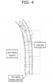
- FIG. 4 illustrates an exemplary process for generating a control point regarding the traveling trajectory of a front vehicle according to an embodiment of the present disclosure.
- the front vehicle F may generate a vision-based trajectory on the basis of rear image information output through a rear camera and front image information received from a rear vehicle.
- the front vehicle F may then generate coordinates of a control point regarding the traveling trajectory of the front vehicle through the vision-based trajectory.
- FIG. 5 is a flowchart illustrating a process of performing feedback regarding reinforcement learning on the basis of a control point regarding the traveling trajectory of a front vehicle according to an embodiment of the present disclosure.
- the learning device 100 is controlling the pertinent vehicle so as to follow the traveling trajectory of the front vehicle as a result of reinforcement learning performed on the basis of image information and a feedback signal.
- the compensation determination unit 200 may receive the coordinate of a control point regarding the traveling trajectory of the front vehicle from the front vehicle (S201).
- the platooning control device may generate the traveling trajectory of the pertinent vehicle through the coordinate of the control point regarding the traveling trajectory of the front vehicle (S203).
- the compensation determination unit 200 may compare the coordinate of the pertinent vehicle with the coordinate of the control point (S205, S211), and may generate a feedback signal according to the result of comparison (S207, S213).
- the compensation determination unit 200 may first determine whether the coordinate of the pertinent vehicle is on the outside of the traveling lane in comparison with the coordinate of the control point (S205).
- the compensation determination unit 200 may output a feedback signal corresponding to negative feedback.
- the learning device 100 may control the amount of braking of the pertinent vehicle to increase according to the negative feedback and may control the steering angle of the pertinent vehicle (S209).
- the compensation determination unit 200 may determine whether the coordinate of the pertinent vehicle is outside a preconfigured danger distance from the coordinate of the control point (S211).
- the compensation determination unit 200 may output a feedback signal corresponding to negative feedback (S207).
- the learning device 100 may control the amount of braking of the pertinent vehicle to increase according to the negative feedback and may control the steering angle of the pertinent vehicle (S209).
- the compensation determination unit 200 may output a feedback signal corresponding to positive feedback (S213).
- FIG. 6 illustrates a process of performing feedback according to the coordinate of the pertinent vehicle during platooning according to an embodiment of the present disclosure.
- first to fourth control points ⁇ 1:4> regarding the traveling trajectory of the front vehicle F are illustrated.
- the center of FIG. 6 corresponds to a case in which the coordinate of the pertinent vehicle R is on the outside of the traveling lane in comparison with the coordinate of the second control point ⁇ 2>.
- the compensation determination unit 200 may then output a feedback signal corresponding to negative feedback.
- the right of FIG. 6 corresponds to a case in which the coordinate of the pertinent vehicle R is on the inside of the traveling lane in comparison with the coordinate of the second control point ⁇ 2>, and is within a danger distance from the coordinate of the second control point ⁇ 2>.
- the compensation determination unit 200 may then output a feedback signal corresponding to positive feedback.
- FIG. 7 is a flowchart illustrating a process of performing feedback regarding reinforcement learning on the basis of RSSI of a radio signal received from the front vehicle according to an embodiment of the present disclosure.
- the learning device 100 is controlling the pertinent vehicle so as to follow the traveling trajectory of the front vehicle as a result of reinforcement learning performed on the basis of image information and a feedback signal.
- the compensation determination unit 200 may receive a radio signal from the front vehicle (S301), and may measure the RSSI of the radio signal (S303).
- the compensation determination unit 200 may determine whether the RSSI of the radio signal is included in a preconfigured range (S305, S311), and may output a feedback signal corresponding to one of positive feedback and negative feedback according to the result of determination (S307, S313, S317).
- the compensation determination unit 200 may first determine whether the RSSI of the radio signal is lower than the upper threshold of the preconfigured range (S305).
- the compensation determination unit 200 may output a feedback signal corresponding to negative feedback (S307).
- the learning device 100 may control the amount of braking of the pertinent vehicle to increase according to the negative feedback (S309).
- the compensation determination unit 200 may determine whether the RSSI is higher than the lower threshold of the preconfigured range (S311).
- the compensation determination unit 200 may output a feedback signal corresponding to negative feedback (S313).
- the learning device 100 may control the acceleration of the pertinent vehicle to increase according to the negative feedback (S315).
- the compensation determination unit 200 may output a feedback signal corresponding to positive feedback (S317).
- the present disclosure as described above may be implemented as codes in a computer-readable medium in which a program is recorded.
- the computer-readable medium includes all types of recording devices in which data readable by a computer system are stored. Examples of the computer-readable medium include a hard disk drive (HDD), a solid state disk (SSD), a silicon disk drive (SDD), a ROM, a RAM, a CD-ROM, a magnetic tape, a floppy disk, an optical data storage device, and the like.
- HDD hard disk drive
- SSD solid state disk
- SDD silicon disk drive
- ROM read only memory
- RAM random access memory
- CD-ROM compact disc read only memory
- magnetic tape magnetic tape
- a floppy disk floppy disk
- optical data storage device and the like.
Landscapes
- Engineering & Computer Science (AREA)
- Physics & Mathematics (AREA)
- General Physics & Mathematics (AREA)
- Automation & Control Theory (AREA)
- Mechanical Engineering (AREA)
- Transportation (AREA)
- Theoretical Computer Science (AREA)
- Life Sciences & Earth Sciences (AREA)
- Remote Sensing (AREA)
- Radar, Positioning & Navigation (AREA)
- Aviation & Aerospace Engineering (AREA)
- Mathematical Physics (AREA)
- Evolutionary Computation (AREA)
- Health & Medical Sciences (AREA)
- Computing Systems (AREA)
- Software Systems (AREA)
- General Health & Medical Sciences (AREA)
- Atmospheric Sciences (AREA)
- Artificial Intelligence (AREA)
- Combustion & Propulsion (AREA)
- Chemical & Material Sciences (AREA)
- Biomedical Technology (AREA)
- Data Mining & Analysis (AREA)
- Molecular Biology (AREA)
- General Engineering & Computer Science (AREA)
- Computational Linguistics (AREA)
- Biophysics (AREA)
- Multimedia (AREA)
- Human Computer Interaction (AREA)
- Computer Vision & Pattern Recognition (AREA)
- Medical Informatics (AREA)
- Databases & Information Systems (AREA)
- Control Of Driving Devices And Active Controlling Of Vehicle (AREA)
- Traffic Control Systems (AREA)
Abstract
Description
- The present disclosure relates to platooning control device and a platooning control method wherein reinforcement learning is performed so as to follow the traveling trajectory of a front vehicle during platooning.
- In general, platooning refers to driving a group of multiple vehicles on roads while sharing traveling information with each other and considering external environments.
- In order to conduct stable platooning, it is crucial to maintain appropriate distances between platooning vehicles and to control rear vehicles to follow the traveling trajectory of front vehicles.
- An autonomous driving system may perform reinforcement learning regarding platooning such that autonomous driving vehicles take optimal actions during platooning.
- The reinforcement learning is one of machine learning methods for learning which action, if taken, would give an optimal result in the current state through trial and error. A reward is given each time an action is taken, and the learning proceeds so as to maximize such rewards.
- The above descriptions regarding background technologies have been made only to help understanding of the background of the present disclosure, and are not to be deemed by those skilled in the art to correspond to already-known prior arts.
- Accordingly, it is an aspect of the present disclosure to perform reinforcement learning by using a control point regarding the traveling trajectory of a front vehicle and image information during platooning such that the pertinent vehicle follows the traveling trajectory of the front vehicle stably and efficiently.
- The technical subjects pursued in the present disclosure may not be limited to the above mentioned technical subjects, and other technical subjects which are not mentioned may be clearly understood, through the following descriptions, by those skilled in the art to which the present disclosure pertains.
- In accordance with an aspect of the present disclosure, a platooning control device may include: a learning device configured to perform reinforcement learning on the basis of image information and a feedback signal and to control a pertinent vehicle so as to follow a traveling trajectory of a front vehicle according to a result of the reinforcement learning; and a compensation determination unit configured to receive a coordinate of a control point regarding the traveling trajectory of the front vehicle from the front vehicle and to compare a coordinate of the pertinent vehicle with the coordinate of the control point, thereby generating the feedback signal.
- In accordance with another aspect of the present disclosure, a platooning control method may include: controlling a pertinent vehicle so as to follow a traveling trajectory of a front vehicle according to a result of reinforcement learning performed on the basis of image information and a feedback signal; receiving a coordinate of a control point regarding the traveling trajectory of the front vehicle from the front vehicle; and generating the feedback signal by comparing a coordinate of the pertinent vehicle with the coordinate of the control point.
- The present disclosure is advantageous in that reinforcement learning is performed by using a control point regarding the traveling trajectory of a front vehicle and image information during platooning such that the pertinent vehicle follows the traveling trajectory of the front vehicle stably and efficiently.
- Advantageous effects obtainable from the present disclosure may not be limited to the above mentioned effects, and other effects which are not mentioned may be clearly understood, through the following descriptions, by those skilled in the art to which the present disclosure pertains.
- The above and other aspects, features, and advantages of the present disclosure will be more apparent from the following detailed description taken in conjunction with the accompanying drawings, in which:
-
FIG. 1 is a block diagram illustrating an exemplary configuration of a platooning control device according to an embodiment of the present disclosure; -
FIG. 2 is a sequence diagram illustrating a process of exchanging information between a front vehicle and a pertinent vehicle during platooning according to an embodiment of the present disclosure; -
FIG. 3 illustrates front and rear images of vehicles which are platooning according to an embodiment of the present disclosure; -
FIG. 4 illustrates an exemplary process for generating a control point regarding the traveling trajectory of a front vehicle according to an embodiment of the present disclosure; -
FIG. 5 is a flowchart illustrating a process of performing feedback regarding reinforcement learning on the basis of a control point regarding the traveling trajectory of a front vehicle according to an embodiment of the present disclosure; -
FIG. 6 illustrates a process of performing feedback according to the coordinate of the pertinent vehicle during platooning according to an embodiment of the present disclosure; and -
FIG. 7 is a flowchart illustrating a process of performing feedback regarding reinforcement learning on the basis of radio signal strength of a radio signal received from the front vehicle according to an embodiment of the present disclosure. - Hereinafter, embodiments disclosed in the present specification will be described in detail with reference to the accompanying drawings, and the same or similar elements are given the same and similar reference numerals, so duplicate descriptions thereof will be omitted.
- In describing the embodiments disclosed in the present specification, when the detailed description of the relevant known technology is determined to unnecessarily obscure the gist of the present disclosure, the detailed description may be omitted. Further, the accompanying drawings are provided only for easy understanding of the embodiments disclosed in the present specification, and the technical spirit disclosed herein is not limited to the accompanying drawings, and it should be understood that all changes, equivalents, or substitutes thereof are included in the spirit and scope of the present disclosure.
- Terms including an ordinal number such as "first", "second", or the like may be used to describe various elements, but the elements are not limited to the terms. The above terms are used only for the purpose of distinguishing one element from another element.
- A singular expression may include a plural expression unless they are definitely different in a context.
- As used herein, the expression "include" or "have" are intended to specify the existence of mentioned features, numbers, steps, operations, elements, components, or combinations thereof, and should be construed as not precluding the possible existence or addition of one or more other features, numbers, steps, operations, elements, components, or combinations thereof.
-
FIG. 1 is a block diagram illustrating an exemplary configuration of a platooning control device according to an embodiment of the present disclosure. - As illustrated in
FIG. 1 , the platooning control device may include alearning device 100, acompensation determination unit 200, and an inferringneural network device 300. - The platooning control device according to an embodiment of the present disclosure may perform reinforcement learning by using the traveling trajectory of a front vehicle and image information during platooning such that the pertinent vehicle is controlled to follow the traveling trajectory of the front vehicle stably and efficiently.
- Respective components of the platooning control device will now be descri bed.
- The
learning device 100 may correspond to an agent which is the target of reinforcement learning regarding platooning. - The
learning device 100 may perform reinforcement learning through a neural network on the basis of image information and a feedback signal, and may output a steering control signal, a braking control signal, and an acceleration control signal such that the pertinent vehicle is controlled to follow the traveling trajectory of the front vehicle according to the result of reinforcement learning. - The image information may include front image information output from a front camera of the pertinent vehicle, and rear image information output from a rear camera of the front vehicle. The front image information and the rear image information may correspond to platooning-related states, and may reflect the characteristics of the real road along which the pertinent vehicle is traveling. Accordingly, the
learning device 100 may perform reinforcement learning through front image information and rear image information corresponding to the current platooning state such that, even in an exceptional platooning situation, the pertinent vehicle is controlled to safely follow the traveling trajectory of the front vehicle. - The feedback signal may correspond to a reward regarding reinforcement learning. More particularly, the feedback signal may indicate one of positive feedback and negative feedback regarding whether the pertinent vehicle follows the traveling trajectory of the front car. Accordingly, the
learning device 100 may change and modify the policy regarding reinforcement learning according to the feedback signal. - The steering control signal, the braking control signal, and the acceleration control signal may correspond to actions regarding reinforcement learning, and may be generated to perform steering control, braking control, and acceleration control of the pertinent vehicle.
- More particularly, the
learning device 100 may transfer a control signal necessary for traveling of the pertinent vehicle to traveling-related controllers for steering, braking, driving, and the like, thereby controlling the traveling state of the pertinent vehicle. - For example, the
learning device 100 may output a steering control signal to a steering controller (not illustrated) configured to adjust the rotational angle of the steering wheel, for example, thereby controlling the steering angle of the pertinent vehicle, and may output a braking control signal to a braking controller (not illustrated) configured to adjust the amount of hydraulic braking or to a motor controller (not illustrated) configured to adjust the amount of regenerative braking, thereby controlling the amount of braking of the pertinent vehicle. In addition, thelearning device 100 may output an acceleration control signal to a powertrain controller (not illustrated) configured to adjust the output torque of the electric motor or engine, thereby controlling the acceleration of the pertinent vehicle. - The
compensation determination unit 200 may generate a feedback signal corresponding to a reward regarding reinforcement learning on the basis of a steering control signal, a braking control signal, and an acceleration control signal corresponding to actions regarding reinforcement learning. - In addition,
compensation determination unit 200 may receive the coordinate of a control point regarding the traveling trajectory of the front vehicle from the front vehicle, and may compare the coordinate of the pertinent vehicle with the coordinate of the control point, thereby generating a feedback signal. - In the present embodiment, the control point may be defined as a feature point for controlling the shape of a spline curve corresponding to the traveling trajectory of the front vehicle.
- The spline curve may correspond to a smooth curve for expressing the traveling trajectory of the front vehicle by using a spline function. Depending on the embodiment, the spline curve may correspond to one of an interpolating spline curve extending through control points, or an approximating spline curve not extending through intermediate control points. A different configuration may be made, depending on the embodiment, regarding whether the approximating spline curve extends through the starting control point and the ending control point.
- A method for operating the
compensation determination unit 200 so as to generate a feedback signal, assuming that the spline curve corresponding to the traveling trajectory of the front vehicle corresponds to an approximating spline curve, will now be described. - When the coordinate of the pertinent vehicle is on the outside of the traveling lane in comparison with the coordinate of a control point, the
compensation determination unit 200 may determine that the pertinent vehicle has deviated from the traveling trajectory of the front vehicle toward the control point, and may output a feedback signal corresponding to negative feedback. The traveling lane refers to the lane along which the pertinent vehicle is currently traveling. - In addition, when the coordinate of the pertinent vehicle is out of a preconfigured danger distance from the coordinate of the control point, the
compensation determination unit 200 may determine that the pertinent vehicle has deviated from the traveling trajectory of the front vehicle in the opposite direction to the control point, and may output a feedback signal corresponding to negative feedback. - When negative feedback is input as a result of coordinate comparison between the pertinent vehicle and the control point, the
learning device 100 may control the amount of braking of the pertinent vehicle to increase through a braking control signal, and may control the steering angle of the pertinent vehicle to follow the traveling trajectory of the front vehicle through a steering control signal. - To the contrary, if the coordinate of the pertinent vehicle is on the inside of the traveling lane in comparison with the control point coordinate, and if the coordinate of the pertinent vehicle is within the preconfigured danger distance from the coordinate of the control point, the
compensation determination unit 200 may determine the pertinent vehicle stably follows the traveling trajectory of the front vehicle. In this case, thecompensation determination unit 200 may output a feedback signal corresponding to positive feedback. - Accordingly, the
compensation determination unit 200 according to the present embodiment may provide thelearning device 100 with feedback regarding whether the pertinent vehicle follows the traveling trajectory of the front vehicle on the basis of the coordinate of a control point regarding the traveling trajectory of the front vehicle, thereby reducing the data size and the amount of calculation regarding the traveling trajectory of the front vehicle. - In addition, the
compensation determination unit 200 may generate a feedback signal according to whether the radio signal strength (for example, received signal strength indication (RSSI)) of a radio signal received from the front vehicle is included in a preconfigured range. The preconfigured range regarding the RSSI may be variously configured depending on the embodiment. - The RSSI of the radio signal may indicate the inter-vehicle distance between the pertinent vehicle and the front vehicle. For example, the
compensation determination unit 200 may determine that the higher the RSSI, the shorter the inter-vehicle distance between the pertinent vehicle and the front vehicle. - If the RSSI of the radio signal is included in the preconfigured range, the
compensation determination unit 200 may determine that the pertinent vehicle stably maintains the inter-vehicle distance from the front vehicle, and may output a feedback signal corresponding to positive feedback. - To the contrary, if the RSSI of the radio signal is not included in the preconfigured range, the
compensation determination unit 200 may output a feedback signal corresponding to negative feedback. - More particularly, if the RSSI of the radio signal is higher than the upper threshold of the preconfigured range, the
compensation determination unit 200 may determine that the inter-vehicle distance between the pertinent vehicle and the front vehicle is short, and may output a feedback signal corresponding to negative feedback. Thelearning device 100 may control the amount of braking of the pertinent vehicle to increase through a braking control signal. - To the contrary, if the RSSI of the radio signal is lower than the lower threshold of the preconfigured range, the
compensation determination unit 200 may determine that the inter-vehicle distance between the pertinent vehicle and the front vehicle is long, and may output a feedback signal corresponding to negative feedback. Thelearning device 100 may control the acceleration of the pertinent vehicle to increase through an acceleration control signal. - Accordingly, the
compensation determination unit 200 according to the present embodiment may provide thelearning device 100 with feedback regarding whether the inter-vehicle distance between the pertinent vehicle and the front vehicle is stably maintained through the RSSI of the radio signal, thereby controlling thelearning device 100 to learn acceleration and braking characteristics regarding the distance from the front vehicle. - In connection with implementation, the
compensation determination unit 200 corresponds to a controller dedicated to feedback regarding reinforcement learning of thelearning device 100, and to this end may include a communication device configured to communicate with another controller or sensor, a memory configured to store an operating system, logic commands, input/output information, and the like, and at least one processor configured to perform determination, calculation, determination, and the like necessary for corresponding function control. - The inferring
neural network device 300 may periodically update a parameter regarding a neural network included in thelearning device 100 after stabilization of reinforcement learning regarding platooning performed by thelearning device 100. - The inferring
neural network device 300 may receive front image information and rear image information and may control the pertinent vehicle so as to follow the traveling trajectory of the front vehicle, on the basis of the updated parameter, without feedback from thecompensation determination unit 200. The inferringneural network device 300 may output a steering control signal, a braking control signal, and an acceleration control signal as in the case of thelearning device 100 such that the pertinent vehicle is controlled to follow the traveling trajectory of the front vehicle. - Accordingly, the inferring
neural network device 300 may perform steering control, braking control, and acceleration control of the pertinent vehicle only through image information without additional reinforcement learning after stabilization of reinforcement learning regarding platooning, thereby reducing the amount of calculation regarding reinforcement learning of the platooning control device. -
FIG. 2 is a sequence diagram illustrating a process of exchanging information between a front vehicle and a pertinent vehicle during platooning according to an embodiment of the present disclosure. - In
FIG. 2 , the pertinent vehicle R has the configuration described with reference toFIG. 1 , and the front vehicle F is assumed to be a vehicle which is platooning together with the pertinent vehicle R, and which support communication with the pertinent vehicle R directly or through an infrastructure or the like. - The front vehicle F may down-scale and compress image information output from a rear camera, thereby generating rear image information (S101), and the pertinent vehicle R may down-scale and compress image information output from a front camera, thereby generating front image information (S103).
- The front vehicle F may transmit rear image information and a radio signal to the pertinent vehicle R, and the pertinent vehicle R may transmit front image information and a radio signal to the front vehicle F (S105).
- The front vehicle F may restore the received front image information and may measure the RSSI of the radio signal received from the pertinent vehicle R (S107). Likewise, the pertinent vehicle R may restore the rear image information and may measure the RSSI of the radio signal received from the front vehicle F (S109).
- The front vehicle F may generate a vision-based trajectory through image information output from the rear camera and the front image information received from the pertinent vehicle R (S111), and may generate the coordinate of a control point according to the vision-based trajectory (S113).
- The front vehicle F may transmit the coordinate of the control point to the pertinent vehicle R (S115).
- The pertinent vehicle R may conduct feedback regarding reinforcement learning on the basis of the coordinate of the control point and a measurement value regarding the RSSI of the radio signal (S117), and may perform steering control, braking control, and acceleration control of the pertinent vehicle R according to the feedback, thereby following the traveling trajectory of the front vehicle F (S119).
-
FIG. 3 illustrates front and rear images of vehicles which are platooning according to an embodiment of the present disclosure. - Referring to
FIG. 3 , a first front vehicle F<1> is positioned in front of a pertinent vehicle R, and a second front vehicle F<2> is positioned in front of the first front vehicle F<1>. A front image FV may be captured through the front camera of each vehicle, and a rear image RV may be captured through the rear camera of each vehicle. - The
learning device 100 of the pertinent vehicle R may determine an overlapping part between a rear image RV of the first front vehicle F<1> and a front image FV captured by the pertinent vehicle R on the basis of front image information of the pertinent vehicle R and rear image information of the first front vehicle F<1>, and may use the determined degree of overlapping between the rear image RV and the front image V as learning data regarding reinforcement learning. - For example, the
learning device 100 may determine the degree of overlapping on the basis of lanes, shapes marked on road surfaces (for example, road surface signs), feature point extraction, and the like, but this is only an example and is not limiting in any manner. -
FIG. 4 illustrates an exemplary process for generating a control point regarding the traveling trajectory of a front vehicle according to an embodiment of the present disclosure. - Referring to
FIG. 4 , the front vehicle F may generate a vision-based trajectory on the basis of rear image information output through a rear camera and front image information received from a rear vehicle. The front vehicle F may then generate coordinates of a control point regarding the traveling trajectory of the front vehicle through the vision-based trajectory. -
FIG. 5 is a flowchart illustrating a process of performing feedback regarding reinforcement learning on the basis of a control point regarding the traveling trajectory of a front vehicle according to an embodiment of the present disclosure. - It will be assumed in
FIG. 5 that thelearning device 100 is controlling the pertinent vehicle so as to follow the traveling trajectory of the front vehicle as a result of reinforcement learning performed on the basis of image information and a feedback signal. - The
compensation determination unit 200 may receive the coordinate of a control point regarding the traveling trajectory of the front vehicle from the front vehicle (S201). The platooning control device may generate the traveling trajectory of the pertinent vehicle through the coordinate of the control point regarding the traveling trajectory of the front vehicle (S203). - The
compensation determination unit 200 may compare the coordinate of the pertinent vehicle with the coordinate of the control point (S205, S211), and may generate a feedback signal according to the result of comparison (S207, S213). - The
compensation determination unit 200 may first determine whether the coordinate of the pertinent vehicle is on the outside of the traveling lane in comparison with the coordinate of the control point (S205). - When the coordinate of the pertinent vehicle is on the outside of the traveling lane in comparison with the coordinate of the control point (YES in S205), the
compensation determination unit 200 may output a feedback signal corresponding to negative feedback. Thelearning device 100 may control the amount of braking of the pertinent vehicle to increase according to the negative feedback and may control the steering angle of the pertinent vehicle (S209). - When the coordinate of the pertinent vehicle is on the inside of the traveling lane in comparison with the coordinate of the control point (NO in S205), the
compensation determination unit 200 may determine whether the coordinate of the pertinent vehicle is outside a preconfigured danger distance from the coordinate of the control point (S211). - When the coordinate of the pertinent vehicle is outside the preconfigured danger distance from the coordinate of the control point (YES in S211), the
compensation determination unit 200 may output a feedback signal corresponding to negative feedback (S207). Thelearning device 100 may control the amount of braking of the pertinent vehicle to increase according to the negative feedback and may control the steering angle of the pertinent vehicle (S209). - When the coordinate of the pertinent vehicle is within the preconfigured danger distance from the coordinate of the control point (NO in S211), the
compensation determination unit 200 may output a feedback signal corresponding to positive feedback (S213). -
FIG. 6 illustrates a process of performing feedback according to the coordinate of the pertinent vehicle during platooning according to an embodiment of the present disclosure. - Referring to the left of
FIG. 6 , first to fourth control points <1:4> regarding the traveling trajectory of the front vehicle F are illustrated. - The center of
FIG. 6 corresponds to a case in which the coordinate of the pertinent vehicle R is on the outside of the traveling lane in comparison with the coordinate of the second control point <2>. Thecompensation determination unit 200 may then output a feedback signal corresponding to negative feedback. - The right of
FIG. 6 corresponds to a case in which the coordinate of the pertinent vehicle R is on the inside of the traveling lane in comparison with the coordinate of the second control point <2>, and is within a danger distance from the coordinate of the second control point <2>. Thecompensation determination unit 200 may then output a feedback signal corresponding to positive feedback. -
FIG. 7 is a flowchart illustrating a process of performing feedback regarding reinforcement learning on the basis of RSSI of a radio signal received from the front vehicle according to an embodiment of the present disclosure. - It will be assumed in
FIG. 7 that thelearning device 100 is controlling the pertinent vehicle so as to follow the traveling trajectory of the front vehicle as a result of reinforcement learning performed on the basis of image information and a feedback signal. - The
compensation determination unit 200 may receive a radio signal from the front vehicle (S301), and may measure the RSSI of the radio signal (S303). - The
compensation determination unit 200 may determine whether the RSSI of the radio signal is included in a preconfigured range (S305, S311), and may output a feedback signal corresponding to one of positive feedback and negative feedback according to the result of determination (S307, S313, S317). - The
compensation determination unit 200 may first determine whether the RSSI of the radio signal is lower than the upper threshold of the preconfigured range (S305). - When the RSSI is higher than the upper threshold of the preconfigured range (NO in S305), the
compensation determination unit 200 may output a feedback signal corresponding to negative feedback (S307). Thelearning device 100 may control the amount of braking of the pertinent vehicle to increase according to the negative feedback (S309). - When the RSSI is lower than the upper threshold of the preconfigured range (YES in S305), the
compensation determination unit 200 may determine whether the RSSI is higher than the lower threshold of the preconfigured range (S311). - When the RSSI is lower than the lower threshold of the preconfigured range (NO in S311), the
compensation determination unit 200 may output a feedback signal corresponding to negative feedback (S313). Thelearning device 100 may control the acceleration of the pertinent vehicle to increase according to the negative feedback (S315). - When the RSSI is higher than the lower threshold of the preconfigured range (YES in S311), the
compensation determination unit 200 may output a feedback signal corresponding to positive feedback (S317). - The present disclosure as described above may be implemented as codes in a computer-readable medium in which a program is recorded. The computer-readable medium includes all types of recording devices in which data readable by a computer system are stored. Examples of the computer-readable medium include a hard disk drive (HDD), a solid state disk (SSD), a silicon disk drive (SDD), a ROM, a RAM, a CD-ROM, a magnetic tape, a floppy disk, an optical data storage device, and the like. Further, the above detailed description should not be constured in a limitative sense, but shold be considered in an illustrative sense in all aspects. The scope of the present disclosure should not be determined by resonable interpretation of the appended claims, and all changes and modifications within the equivalent scope of the present disclosure fall within the scope of the present disclosure.
Claims (15)
- A platooning control device comprising:a learning device (100) configured to perform reinforcement learning on the basis of image information and a feedback signal and to control a pertinent vehicle so as to follow a traveling trajectory of a front vehicle according to a result of the reinforcement learning; anda compensation determination unit (200) configured to receive a coordinate of a control point regarding the traveling trajectory of the front vehicle from the front vehicle and to compare a coordinate of the pertinent vehicle with the coordinate of the control point, thereby generating the feedback signal.
- The platooning control device of claim 1, wherein the image information comprises front image information output from a front camera of the pertinent vehicle and rear image information output from a rear camera of the front vehicle.
- The platooning control device of claim 2, wherein the learning device determines an overlapping part between a rear image of the front vehicle and a front image of the pertinent vehicle on the basis of the front image information and the rear image information, and determines a degree of overlapping between the rear image and the front image according to a result of determination as learning data regarding the reinforcement learning.
- The platooning control device of any one of the preceding claims, wherein the feedback signal indicates one of positive feedback and negative feedback regarding whether the pertinent vehicle follows the traveling trajectory of the front vehicle.
- The platooning control device of any one of the preceding claims, wherein the control point corresponds to a point for controlling the shape of a spline curve corresponding to the traveling trajectory of the front vehicle.
- The platooning control device of any one of the preceding claims, wherein the compensation determination unit outputs the feedback signal corresponding to negative feedback when the coordinate of the pertinent vehicle is on the outside of a traveling lane in comparison with the coordinate of the control point.
- The platooning control device of claim 6, wherein the learning device increases an amount of braking of the pertinent vehicle when the negative feedback is output, and controls a steering angle of the pertinent vehicle so as to follow the traveling trajectory of the front vehicle.
- The platooning control device of any one of the preceding claims, wherein the compensation determination unit outputs the feedback signal corresponding to negative feedback when the coordinate of the pertinent vehicle is outside a preconfigured danger distance from the coordinate of the control point.
- The platooning control device of any one of the preceding claims, wherein the compensation determination unit outputs the feedback signal corresponding to positive feedback when the coordinate of the pertinent vehicle is on the inside of a traveling lane in comparison with the coordinate of the control point, and when the coordinate of the pertinent vehicle is within a preconfigured danger distance from the coordinate of the control point.
- The platooning control device of any one of the preceding claims, wherein the compensation determination unit outputs the feedback signal corresponding to one of positive feedback and negative feedback according to whether received signal strength of a radio signal received from the front vehicle is in a preconfigured range.
- The platooning control device of any one of the preceding claims, further comprising an inferring neural network device configured to update a parameter regarding a neural network included in the learning device, to receive the image information on the basis of the updated parameter, and to control the pertinent vehicle so as to follow the traveling trajectory of the front vehicle.
- A platooning control method comprising:controlling a pertinent vehicle so as to follow a traveling trajectory of a front vehicle according to a result of reinforcement learning performed on the basis of image information and a feedback signal;receiving a coordinate of a control point regarding the traveling trajectory of the front vehicle from the front vehicle (S201); andgenerating the feedback signal by comparing a coordinate of the pertinent vehicle with the coordinate of the control point (S207, S213).
- The platooning control method of claim 12, wherein the image information comprises front image information output from a front camera of the pertinent vehicle and rear image information output from a rear camera of the front vehicle.
- The platooning control method of any one of the preceding claims, wherein the control point corresponds to a point for controlling the shape of a spline curve corresponding to the traveling trajectory of the front vehicle.
- The platooning control method of any one of the preceding claims, further comprising:receiving a radio signal from the front vehicle;determining whether received signal strength of the radio signal is in a preconfigured range; andoutputting the feedback signal corresponding to one of positive feedback and negative feedback according to a result of the determining.
Applications Claiming Priority (1)
| Application Number | Priority Date | Filing Date | Title |
|---|---|---|---|
| KR1020220107758A KR20240029394A (en) | 2022-08-26 | 2022-08-26 | Platooning control apparatus and control method of platooning |
Publications (2)
| Publication Number | Publication Date |
|---|---|
| EP4328697A1 true EP4328697A1 (en) | 2024-02-28 |
| EP4328697B1 EP4328697B1 (en) | 2025-08-13 |
Family
ID=84421316
Family Applications (1)
| Application Number | Title | Priority Date | Filing Date |
|---|---|---|---|
| EP22211624.6A Active EP4328697B1 (en) | 2022-08-26 | 2022-12-06 | Platooning control device and platooning control method |
Country Status (4)
| Country | Link |
|---|---|
| US (1) | US12265397B2 (en) |
| EP (1) | EP4328697B1 (en) |
| KR (1) | KR20240029394A (en) |
| CN (1) | CN117687402A (en) |
Citations (2)
| Publication number | Priority date | Publication date | Assignee | Title |
|---|---|---|---|---|
| US6032097A (en) * | 1996-11-27 | 2000-02-29 | Honda Giken Kogyo Kabushiki Kaisha | Vehicle platoon control system |
| CN105035085A (en) * | 2015-07-31 | 2015-11-11 | 奇瑞汽车股份有限公司 | Method and device for automatic car following |
Family Cites Families (9)
| Publication number | Priority date | Publication date | Assignee | Title |
|---|---|---|---|---|
| JP6590270B2 (en) * | 2016-05-16 | 2019-10-16 | 本田技研工業株式会社 | Vehicle control system, vehicle control method, and vehicle control program |
| EP3638542B1 (en) * | 2017-06-16 | 2022-01-26 | Nauto, Inc. | System and method for contextualized vehicle operation determination |
| KR101984922B1 (en) * | 2017-09-13 | 2019-05-31 | 엘지전자 주식회사 | Method for platooning of vehicles and vehicle |
| CN109664854B (en) * | 2017-10-17 | 2020-11-03 | 杭州海康威视数字技术股份有限公司 | A car warning method, device and electronic equipment |
| CN111301411B (en) * | 2018-12-10 | 2021-04-20 | 广州汽车集团股份有限公司 | Vehicle travel control method and device |
| US10635915B1 (en) * | 2019-01-30 | 2020-04-28 | StradVision, Inc. | Method and device for warning blind spot cooperatively based on V2V communication with fault tolerance and fluctuation robustness in extreme situation |
| CN114137512B (en) * | 2021-11-29 | 2024-04-26 | 湖南大学 | A method for tracking multiple vehicles ahead by integrating millimeter-wave radar and deep learning vision |
| JP7615018B2 (en) * | 2021-12-16 | 2025-01-16 | 株式会社東芝 | Machine learning device, machine learning method, and machine learning program |
| JP2023176420A (en) * | 2022-05-31 | 2023-12-13 | フォルシアクラリオン・エレクトロニクス株式会社 | Display controller and display control method |
-
2022
- 2022-08-26 KR KR1020220107758A patent/KR20240029394A/en active Pending
- 2022-12-06 EP EP22211624.6A patent/EP4328697B1/en active Active
- 2022-12-12 US US18/079,444 patent/US12265397B2/en active Active
- 2022-12-20 CN CN202211640491.7A patent/CN117687402A/en active Pending
Patent Citations (2)
| Publication number | Priority date | Publication date | Assignee | Title |
|---|---|---|---|---|
| US6032097A (en) * | 1996-11-27 | 2000-02-29 | Honda Giken Kogyo Kabushiki Kaisha | Vehicle platoon control system |
| CN105035085A (en) * | 2015-07-31 | 2015-11-11 | 奇瑞汽车股份有限公司 | Method and device for automatic car following |
Also Published As
| Publication number | Publication date |
|---|---|
| US12265397B2 (en) | 2025-04-01 |
| CN117687402A (en) | 2024-03-12 |
| KR20240029394A (en) | 2024-03-05 |
| US20240069570A1 (en) | 2024-02-29 |
| EP4328697B1 (en) | 2025-08-13 |
Similar Documents
| Publication | Publication Date | Title |
|---|---|---|
| CN111976741B (en) | Device and method for controlling an autonomous vehicle | |
| CN109895772B (en) | Apparatus and method for controlling platoon travel in a leading vehicle | |
| EP3730370B1 (en) | Method and device for acquiring automatic driving track | |
| US11703883B2 (en) | Autonomous driving device | |
| CN113665574B (en) | Intelligent automobile lane change duration prediction and anthropomorphic track planning method | |
| US10229599B2 (en) | Vehicle lane changing | |
| US20220032952A1 (en) | Control system and control method for a hybrid approach for determining a possible trajectory for a motor vehicle | |
| EP3342670B1 (en) | Method to dynamically adjusting speed control rates of autonomous vehicles | |
| CN114148348A (en) | Stop control method, device and computer program for automatic driving vehicle | |
| CN113734193A (en) | System and method for estimating take over time | |
| CN105109482A (en) | Parking garage entry method and device | |
| US20240152153A1 (en) | Apparatus and method for controlling platooning | |
| CN120308155A (en) | Trajectory optimization method and device, and perception model training method and device | |
| JP2018199458A (en) | Reverse parking assist device of combination vehicle | |
| CN111667719B (en) | Apparatus and method and storage medium for controlling the speed of an autonomous vehicle | |
| EP4328697A1 (en) | Platooning control device and platooning control method | |
| KR20220153708A (en) | Method for Controlling Controller of Vehicle And Vehicle Integrated Controller Therefor | |
| CN115140029B (en) | A method and device for detecting safety capability of an autonomous driving vehicle | |
| CN117302242A (en) | Angle correction method and device, storage medium and electronic device | |
| KR20220006912A (en) | Personal mobility and control method for the same | |
| CN110083158B (en) | Method and equipment for determining local planning path | |
| KR20210142803A (en) | Server and control method for the same | |
| JP2008234593A (en) | Vehicle behavior prediction device | |
| CN109987097B (en) | A method and device for adjusting the motion state of a target vehicle | |
| JP6306429B2 (en) | Steering control system |
Legal Events
| Date | Code | Title | Description |
|---|---|---|---|
| PUAI | Public reference made under article 153(3) epc to a published international application that has entered the european phase |
Free format text: ORIGINAL CODE: 0009012 |
|
| STAA | Information on the status of an ep patent application or granted ep patent |
Free format text: STATUS: REQUEST FOR EXAMINATION WAS MADE |
|
| 17P | Request for examination filed |
Effective date: 20221206 |
|
| AK | Designated contracting states |
Kind code of ref document: A1 Designated state(s): AL AT BE BG CH CY CZ DE DK EE ES FI FR GB GR HR HU IE IS IT LI LT LU LV MC ME MK MT NL NO PL PT RO RS SE SI SK SM TR |
|
| STAA | Information on the status of an ep patent application or granted ep patent |
Free format text: STATUS: EXAMINATION IS IN PROGRESS |
|
| 17Q | First examination report despatched |
Effective date: 20241009 |
|
| REG | Reference to a national code |
Ref country code: DE Ref legal event code: R079 Free format text: PREVIOUS MAIN CLASS: G05D0001020000 Ipc: G05D0001000000 Ref document number: 602022019339 Country of ref document: DE |
|
| GRAP | Despatch of communication of intention to grant a patent |
Free format text: ORIGINAL CODE: EPIDOSNIGR1 |
|
| STAA | Information on the status of an ep patent application or granted ep patent |
Free format text: STATUS: GRANT OF PATENT IS INTENDED |
|
| RIC1 | Information provided on ipc code assigned before grant |
Ipc: G05D 1/00 20240101AFI20250218BHEP |
|
| INTG | Intention to grant announced |
Effective date: 20250321 |
|
| P01 | Opt-out of the competence of the unified patent court (upc) registered |
Free format text: CASE NUMBER: APP_24200/2025 Effective date: 20250521 |
|
| GRAS | Grant fee paid |
Free format text: ORIGINAL CODE: EPIDOSNIGR3 |
|
| GRAA | (expected) grant |
Free format text: ORIGINAL CODE: 0009210 |
|
| STAA | Information on the status of an ep patent application or granted ep patent |
Free format text: STATUS: THE PATENT HAS BEEN GRANTED |
|
| AK | Designated contracting states |
Kind code of ref document: B1 Designated state(s): AL AT BE BG CH CY CZ DE DK EE ES FI FR GB GR HR HU IE IS IT LI LT LU LV MC ME MK MT NL NO PL PT RO RS SE SI SK SM TR |
|
| REG | Reference to a national code |
Ref country code: GB Ref legal event code: FG4D |
|
| REG | Reference to a national code |
Ref country code: CH Ref legal event code: EP |
|
| REG | Reference to a national code |
Ref country code: DE Ref legal event code: R096 Ref document number: 602022019339 Country of ref document: DE |
|
| REG | Reference to a national code |
Ref country code: IE Ref legal event code: FG4D |
|
| REG | Reference to a national code |
Ref country code: NL Ref legal event code: MP Effective date: 20250813 |
|
| PG25 | Lapsed in a contracting state [announced via postgrant information from national office to epo] |
Ref country code: IS Free format text: LAPSE BECAUSE OF FAILURE TO SUBMIT A TRANSLATION OF THE DESCRIPTION OR TO PAY THE FEE WITHIN THE PRESCRIBED TIME-LIMIT Effective date: 20251213 |
|
| PG25 | Lapsed in a contracting state [announced via postgrant information from national office to epo] |
Ref country code: NO Free format text: LAPSE BECAUSE OF FAILURE TO SUBMIT A TRANSLATION OF THE DESCRIPTION OR TO PAY THE FEE WITHIN THE PRESCRIBED TIME-LIMIT Effective date: 20251113 |
|
| REG | Reference to a national code |
Ref country code: LT Ref legal event code: MG9D |
|
| PG25 | Lapsed in a contracting state [announced via postgrant information from national office to epo] |
Ref country code: PT Free format text: LAPSE BECAUSE OF FAILURE TO SUBMIT A TRANSLATION OF THE DESCRIPTION OR TO PAY THE FEE WITHIN THE PRESCRIBED TIME-LIMIT Effective date: 20251215 |
|
| PG25 | Lapsed in a contracting state [announced via postgrant information from national office to epo] |
Ref country code: FI Free format text: LAPSE BECAUSE OF FAILURE TO SUBMIT A TRANSLATION OF THE DESCRIPTION OR TO PAY THE FEE WITHIN THE PRESCRIBED TIME-LIMIT Effective date: 20250813 |
|
| PG25 | Lapsed in a contracting state [announced via postgrant information from national office to epo] |
Ref country code: NL Free format text: LAPSE BECAUSE OF FAILURE TO SUBMIT A TRANSLATION OF THE DESCRIPTION OR TO PAY THE FEE WITHIN THE PRESCRIBED TIME-LIMIT Effective date: 20250813 Ref country code: HR Free format text: LAPSE BECAUSE OF FAILURE TO SUBMIT A TRANSLATION OF THE DESCRIPTION OR TO PAY THE FEE WITHIN THE PRESCRIBED TIME-LIMIT Effective date: 20250813 |
|
| PGFP | Annual fee paid to national office [announced via postgrant information from national office to epo] |
Ref country code: FR Payment date: 20251218 Year of fee payment: 4 |
|
| PG25 | Lapsed in a contracting state [announced via postgrant information from national office to epo] |
Ref country code: GR Free format text: LAPSE BECAUSE OF FAILURE TO SUBMIT A TRANSLATION OF THE DESCRIPTION OR TO PAY THE FEE WITHIN THE PRESCRIBED TIME-LIMIT Effective date: 20251114 |
|
| PG25 | Lapsed in a contracting state [announced via postgrant information from national office to epo] |
Ref country code: SE Free format text: LAPSE BECAUSE OF FAILURE TO SUBMIT A TRANSLATION OF THE DESCRIPTION OR TO PAY THE FEE WITHIN THE PRESCRIBED TIME-LIMIT Effective date: 20250813 |
|
| PG25 | Lapsed in a contracting state [announced via postgrant information from national office to epo] |
Ref country code: LV Free format text: LAPSE BECAUSE OF FAILURE TO SUBMIT A TRANSLATION OF THE DESCRIPTION OR TO PAY THE FEE WITHIN THE PRESCRIBED TIME-LIMIT Effective date: 20250813 |
|
| PG25 | Lapsed in a contracting state [announced via postgrant information from national office to epo] |
Ref country code: BG Free format text: LAPSE BECAUSE OF FAILURE TO SUBMIT A TRANSLATION OF THE DESCRIPTION OR TO PAY THE FEE WITHIN THE PRESCRIBED TIME-LIMIT Effective date: 20250813 Ref country code: PL Free format text: LAPSE BECAUSE OF FAILURE TO SUBMIT A TRANSLATION OF THE DESCRIPTION OR TO PAY THE FEE WITHIN THE PRESCRIBED TIME-LIMIT Effective date: 20250813 |
|
| PG25 | Lapsed in a contracting state [announced via postgrant information from national office to epo] |
Ref country code: RS Free format text: LAPSE BECAUSE OF FAILURE TO SUBMIT A TRANSLATION OF THE DESCRIPTION OR TO PAY THE FEE WITHIN THE PRESCRIBED TIME-LIMIT Effective date: 20251113 |
|
| PG25 | Lapsed in a contracting state [announced via postgrant information from national office to epo] |
Ref country code: ES Free format text: LAPSE BECAUSE OF FAILURE TO SUBMIT A TRANSLATION OF THE DESCRIPTION OR TO PAY THE FEE WITHIN THE PRESCRIBED TIME-LIMIT Effective date: 20250813 |
|
| REG | Reference to a national code |
Ref country code: AT Ref legal event code: MK05 Ref document number: 1825344 Country of ref document: AT Kind code of ref document: T Effective date: 20250813 |
|
| PG25 | Lapsed in a contracting state [announced via postgrant information from national office to epo] |
Ref country code: RO Free format text: LAPSE BECAUSE OF FAILURE TO SUBMIT A TRANSLATION OF THE DESCRIPTION OR TO PAY THE FEE WITHIN THE PRESCRIBED TIME-LIMIT Effective date: 20250813 |
|
| PG25 | Lapsed in a contracting state [announced via postgrant information from national office to epo] |
Ref country code: SM Free format text: LAPSE BECAUSE OF FAILURE TO SUBMIT A TRANSLATION OF THE DESCRIPTION OR TO PAY THE FEE WITHIN THE PRESCRIBED TIME-LIMIT Effective date: 20250813 |
|
| PG25 | Lapsed in a contracting state [announced via postgrant information from national office to epo] |
Ref country code: DK Free format text: LAPSE BECAUSE OF FAILURE TO SUBMIT A TRANSLATION OF THE DESCRIPTION OR TO PAY THE FEE WITHIN THE PRESCRIBED TIME-LIMIT Effective date: 20250813 |
|
| PGFP | Annual fee paid to national office [announced via postgrant information from national office to epo] |
Ref country code: DE Payment date: 20251222 Year of fee payment: 4 |
|
| PG25 | Lapsed in a contracting state [announced via postgrant information from national office to epo] |
Ref country code: AT Free format text: LAPSE BECAUSE OF FAILURE TO SUBMIT A TRANSLATION OF THE DESCRIPTION OR TO PAY THE FEE WITHIN THE PRESCRIBED TIME-LIMIT Effective date: 20250813 |
|
| PG25 | Lapsed in a contracting state [announced via postgrant information from national office to epo] |
Ref country code: IT Free format text: LAPSE BECAUSE OF FAILURE TO SUBMIT A TRANSLATION OF THE DESCRIPTION OR TO PAY THE FEE WITHIN THE PRESCRIBED TIME-LIMIT Effective date: 20250813 |
|
| PG25 | Lapsed in a contracting state [announced via postgrant information from national office to epo] |
Ref country code: CZ Free format text: LAPSE BECAUSE OF FAILURE TO SUBMIT A TRANSLATION OF THE DESCRIPTION OR TO PAY THE FEE WITHIN THE PRESCRIBED TIME-LIMIT Effective date: 20250813 |
|
| PG25 | Lapsed in a contracting state [announced via postgrant information from national office to epo] |
Ref country code: EE Free format text: LAPSE BECAUSE OF FAILURE TO SUBMIT A TRANSLATION OF THE DESCRIPTION OR TO PAY THE FEE WITHIN THE PRESCRIBED TIME-LIMIT Effective date: 20250813 Ref country code: SK Free format text: LAPSE BECAUSE OF FAILURE TO SUBMIT A TRANSLATION OF THE DESCRIPTION OR TO PAY THE FEE WITHIN THE PRESCRIBED TIME-LIMIT Effective date: 20250813 |