EP4328652A1 - Lichtprojektormodul - Google Patents
Lichtprojektormodul Download PDFInfo
- Publication number
- EP4328652A1 EP4328652A1 EP22200040.8A EP22200040A EP4328652A1 EP 4328652 A1 EP4328652 A1 EP 4328652A1 EP 22200040 A EP22200040 A EP 22200040A EP 4328652 A1 EP4328652 A1 EP 4328652A1
- Authority
- EP
- European Patent Office
- Prior art keywords
- optical element
- waveguide
- light beam
- projector module
- light
- Prior art date
- Legal status (The legal status is an assumption and is not a legal conclusion. Google has not performed a legal analysis and makes no representation as to the accuracy of the status listed.)
- Pending
Links
Images


Classifications
-
- G—PHYSICS
- G02—OPTICS
- G02B—OPTICAL ELEMENTS, SYSTEMS OR APPARATUS
- G02B26/00—Optical devices or arrangements for the control of light using movable or deformable optical elements
- G02B26/08—Optical devices or arrangements for the control of light using movable or deformable optical elements for controlling the direction of light
- G02B26/10—Scanning systems
- G02B26/101—Scanning systems with both horizontal and vertical deflecting means, e.g. raster or XY scanners
-
- G—PHYSICS
- G02—OPTICS
- G02B—OPTICAL ELEMENTS, SYSTEMS OR APPARATUS
- G02B27/00—Optical systems or apparatus not provided for by any of the groups G02B1/00 - G02B26/00, G02B30/00
- G02B27/01—Head-up displays
- G02B27/017—Head mounted
- G02B27/0172—Head mounted characterised by optical features
-
- G—PHYSICS
- G02—OPTICS
- G02B—OPTICAL ELEMENTS, SYSTEMS OR APPARATUS
- G02B27/00—Optical systems or apparatus not provided for by any of the groups G02B1/00 - G02B26/00, G02B30/00
- G02B27/10—Beam splitting or combining systems
- G02B27/14—Beam splitting or combining systems operating by reflection only
- G02B27/144—Beam splitting or combining systems operating by reflection only using partially transparent surfaces without spectral selectivity
-
- G—PHYSICS
- G02—OPTICS
- G02B—OPTICAL ELEMENTS, SYSTEMS OR APPARATUS
- G02B6/00—Light guides; Structural details of arrangements comprising light guides and other optical elements, e.g. couplings
- G02B6/0001—Light guides; Structural details of arrangements comprising light guides and other optical elements, e.g. couplings specially adapted for lighting devices or systems
- G02B6/0011—Light guides; Structural details of arrangements comprising light guides and other optical elements, e.g. couplings specially adapted for lighting devices or systems the light guides being planar or of plate-like form
- G02B6/0013—Means for improving the coupling-in of light from the light source into the light guide
- G02B6/0015—Means for improving the coupling-in of light from the light source into the light guide provided on the surface of the light guide or in the bulk of it
- G02B6/0016—Grooves, prisms, gratings, scattering particles or rough surfaces
-
- G—PHYSICS
- G02—OPTICS
- G02B—OPTICAL ELEMENTS, SYSTEMS OR APPARATUS
- G02B6/00—Light guides; Structural details of arrangements comprising light guides and other optical elements, e.g. couplings
- G02B6/0001—Light guides; Structural details of arrangements comprising light guides and other optical elements, e.g. couplings specially adapted for lighting devices or systems
- G02B6/0011—Light guides; Structural details of arrangements comprising light guides and other optical elements, e.g. couplings specially adapted for lighting devices or systems the light guides being planar or of plate-like form
- G02B6/0013—Means for improving the coupling-in of light from the light source into the light guide
- G02B6/0023—Means for improving the coupling-in of light from the light source into the light guide provided by one optical element, or plurality thereof, placed between the light guide and the light source, or around the light source
- G02B6/0031—Reflecting element, sheet or layer
-
- G—PHYSICS
- G02—OPTICS
- G02B—OPTICAL ELEMENTS, SYSTEMS OR APPARATUS
- G02B6/00—Light guides; Structural details of arrangements comprising light guides and other optical elements, e.g. couplings
- G02B6/0001—Light guides; Structural details of arrangements comprising light guides and other optical elements, e.g. couplings specially adapted for lighting devices or systems
- G02B6/0011—Light guides; Structural details of arrangements comprising light guides and other optical elements, e.g. couplings specially adapted for lighting devices or systems the light guides being planar or of plate-like form
- G02B6/0033—Means for improving the coupling-out of light from the light guide
- G02B6/0035—Means for improving the coupling-out of light from the light guide provided on the surface of the light guide or in the bulk of it
- G02B6/0036—2-D arrangement of prisms, protrusions, indentations or roughened surfaces
-
- G—PHYSICS
- G02—OPTICS
- G02B—OPTICAL ELEMENTS, SYSTEMS OR APPARATUS
- G02B27/00—Optical systems or apparatus not provided for by any of the groups G02B1/00 - G02B26/00, G02B30/00
- G02B27/01—Head-up displays
- G02B27/0101—Head-up displays characterised by optical features
- G02B2027/013—Head-up displays characterised by optical features comprising a combiner of particular shape, e.g. curvature
-
- G—PHYSICS
- G02—OPTICS
- G02B—OPTICAL ELEMENTS, SYSTEMS OR APPARATUS
- G02B27/00—Optical systems or apparatus not provided for by any of the groups G02B1/00 - G02B26/00, G02B30/00
- G02B27/01—Head-up displays
- G02B27/017—Head mounted
- G02B2027/0178—Eyeglass type
-
- G—PHYSICS
- G02—OPTICS
- G02B—OPTICAL ELEMENTS, SYSTEMS OR APPARATUS
- G02B26/00—Optical devices or arrangements for the control of light using movable or deformable optical elements
- G02B26/08—Optical devices or arrangements for the control of light using movable or deformable optical elements for controlling the direction of light
- G02B26/0816—Optical devices or arrangements for the control of light using movable or deformable optical elements for controlling the direction of light by means of one or more reflecting elements
- G02B26/0833—Optical devices or arrangements for the control of light using movable or deformable optical elements for controlling the direction of light by means of one or more reflecting elements the reflecting element being a micromechanical device, e.g. a MEMS mirror, DMD
-
- G—PHYSICS
- G02—OPTICS
- G02B—OPTICAL ELEMENTS, SYSTEMS OR APPARATUS
- G02B6/00—Light guides; Structural details of arrangements comprising light guides and other optical elements, e.g. couplings
- G02B6/0001—Light guides; Structural details of arrangements comprising light guides and other optical elements, e.g. couplings specially adapted for lighting devices or systems
- G02B6/0011—Light guides; Structural details of arrangements comprising light guides and other optical elements, e.g. couplings specially adapted for lighting devices or systems the light guides being planar or of plate-like form
- G02B6/0066—Light guides; Structural details of arrangements comprising light guides and other optical elements, e.g. couplings specially adapted for lighting devices or systems the light guides being planar or of plate-like form characterised by the light source being coupled to the light guide
- G02B6/0073—Light emitting diode [LED]
Definitions
- the present invention relates to a light projector module projecting an image, comprising a support, a light source supported by the support and configured to emit in a beam path a light beam carrying said image, a micro-electro-mechanical-system (MEMS) mirror supported by the support and configured to deflect the emitted light beam received over the beam path as a deflected light beam, and a waveguide with two parallel sides, supported by the support and having an in-coupling section configured to couple the deflected light beam into the waveguide, a guiding section configured to guide the deflected light beam through the waveguide as a guided light beam, and an out-coupling section configured to couple the guided light beam out from the waveguide as an expanded light beam whose cross section is larger than the cross section of the deflected light beam.
- MEMS micro-electro-mechanical-system
- An apparatus of this kind is commonly used in AR glasses, AR helmets or head-up displays for a broad range of applications like navigation, training, entertainment, education or work.
- the MEMS mirror deflects the light beam into subsequent directions (angles), one direction (angle) per pixel of the image.
- the MEMS mirror oscillates fast about a vertical axis and slowly about a horizontal axis to sweep the directions and, thus, scan the pixels row by row and line by line.
- the deflected light beam passes a waveguide which enlarges the beam in cross-section - for a so-called "exit pupil” or "eye box” expansion - onto a display viewed by the user.
- the display In VR applications, the display is typically a (miniature) reflective screen in front of the user's eye. In AR applications the display is a semi-transparent combiner which redirects the light beam/s towards the user's eye while concurrently superposing them with light field from a surrounding. In either case the cornea and the lens of the user's eye focus each light beam from a specific direction onto one image point on the retina, so that all image points on the retina then form the image perceived by the user. In video beamer applications the light projector module can be used to project an image onto an external screen like a reflective wall or movie screen. In some applications the light projector may even project the scanned light beam/s directly into the user's eye, without any reflective screen or semi-transparent combiner.
- a light projector module as defined at the outset that is distinguished by an optical element which lies beside the waveguide, overlaps the out-coupling section when seen in a direction substantially perpendicular to the sides of the waveguide, and is configured to focus or defocus the expanded light beam as a focused or defocused output light beam.
- the inventive arrangement of the light source, MEMS mirror waveguide and optical element allows to expand the exit pupil and at the same time to shift the object plane of the image to a desired position and to project the image at a desired magnification.
- the light projector module can project a sharp image at any desired distance and size while allowing for a movement of a user's eye within a large eye box. For example, a focused image of a desired size may be displayed at a distance within an armlength of a worker to augment a work place surrounding while the worker may change his or her gaze to carry out a task.
- having the optical element directly besides the waveguide and overlapping the out-coupling section allows to use a small optical element which still receives the expanded light beam for a wide range of directions. This leads to a tight integration and compact design and, thus, to an optimal user comfort, wearability and portability.
- the optical element may provide the output beam simply with a spherical wavefront.
- the optical element is configured to provide the output light beam with an aspherical wavefront to reduce or avoid optical aberrations such as spherical and comatic aberrations, e.g., of the human eye or other optics downstream the optical element, and to project a particularly sharp image.
- the optical element may direct the scanned light beam directly into the user's eye, e.g. in VR applications.
- the light projector module further comprises a display, in particular a semitransparent combiner or a mirror, supported by the support and configured to direct the output light beam as an image light beam towards the user's eye for projection.
- the display may be a semitransparent combiner, e.g. a semitransparent mirror, a holographic optical element (HOE) or a further waveguide, to superpose the output light beam with the light field of the surrounding;
- the display may be opaque on one side to block the light field of the surrounding and reflective on its other side to project only the output light beam towards the user's eye.
- the interplay of the display and the optical element allows to generate image light beams with a wide variety of shapes, in particular when the output light beam is provided with an aspherical wavefront. Hence, the image beam shape can be adapted to the specific application.
- the invention provides for two particularly advantageous embodiments of this interplay.
- the optical element and the display in combination provide the image light beam with a planar wavefront.
- the object plane of the image is located at infinity and a sharp image is seen when the user's eye is relaxed.
- the optical element and the display may form a particularly simple magnification optics, e.g. similar to a telescope, which magnifies the angular differences of the expanded light beam at subsequent MEMS mirror orientations and, thus, the projected image.
- the optical element and the display in combination provide the image light beam with a spherical wavefront.
- the object plane of the image can be shifted to a desired finite distance simply by adjusting the (fictitious) origin of the spherical image light beam. Consequently, objects in the projected image can be sharply seen at the finite distance and, in AR applications, simultaneously with real objects located at that distance.
- Two beneficial embodiments of the optical element are provided for said focusing or defocusing of the expanded light beam.
- the optical element is a transmissive optical element, in particular a transmissive hologram, a transmissive diffractive optical element (DOE), a diffractive meta surface, or a liquid lens.
- the output light beam traverses the optical element in a direction away from the waveguide and is, thus, not affected thereby.
- the waveguide has a mirror or a reflective coating at that of said two sides that is far from the optical element. In case of a bi-directional out-coupling section, this mirror or coating reflects that part of the expanded light beam that would be coupled-out in a "wrong" direction, i.e. away from the optical element, back towards the optical element and, thus, increases the light efficiency of the projector module.
- the optical element is a reflective optical element, in particular a reflective hologram, a reflective diffractive optical element (DOE), a reflective meta surface, or a liquid mirror.
- DOE diffractive optical element
- the waveguide has a quarter wave plate between the out-coupling section and the optical element and a polariser at that of said two sides that is far from the optical element.
- the light source can emit a polarised light beam, such that the polariser absorbs that part of the expanded light beam which would be coupled out directly, i.e. in a "wrong" direction away from the optical element without being focused or defocused, while letting pass the output light beam with altered polarisation.
- the image light beam can be projected free from any unwanted light.
- a hologram, DOE or meta surface when used as the optical element, it can be made particularly flat and the light projector module can be particularly compact; and when a liquid lens or mirror is used as the optical element, its surface may be dynamically adjusted and, therewith, the waveform of the output beam.
- the optical element is supported movably in the direction substantially perpendicular to the sides of the waveguide.
- the object plane shift and/or the magnification of the image may be dynamically adjusted by moving the optical element.
- the optical element lies beside the waveguide at a distance therefrom which is larger than 10 ⁇ m, preferably larger than 50 ⁇ m, and which is smaller than 1 cm, preferably smaller than 2 mm.
- a distance is as large as to avoid an unwanted leakage of the light beam out from a waveguide working with total internal reflection and as low as to keep the projector module small and compact.
- the optical element is mounted on the waveguide which, in turn, is supported by the support. In this way the optical element and the waveguide can be steadily and accurately aligned with each other.
- the optical element may optionally be mounted on the waveguide via a circumferential rim or a set of rails or studs to ease alignment during assembly.
- the optical element may abut against the waveguide.
- the waveguide and the optical element may be formed as a stack on a common wafer.
- the out-coupling section has an out-coupling efficiency increasing with distance from the in-coupling section.
- the inventive light projector module can be employed in a variety of designs.
- the light projector module further comprises a static mirror which lies, in the beam path from the light source to the MEMS mirror, beside the waveguide and overlaps the waveguide when seen in the direction substantially perpendicular to the sides of the waveguide, and is configured to fold the beam path about an angle of folding. Thereby, the light beam is guided in an optimised path through the module.
- the light source may comprise three LEDs or laser diodes for emitting red, green, and blue beams of light, respectively, and a beam combiner for combining the beams of light to said light beam, to project a colour image.
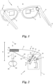
- Fig. 1 shows a pair of augmented reality (AR) glasses 1 comprising a spectacle frame 2, a pair of eye glasses 3 and a pair of temples 4. Attached to each temple 4 is a light projector module 5 which projects an image 6 onto a display (here: a semi-transparent combiner 7).
- the semi-transparent combiner 7 is supported by the spectacle frame 2 or an eyeglass 3 or integrated into the latter.
- the semi-transparent combiner 7, e.g., a semi-transparent mirror, a waveguide or a holographic combiner, superposes the image 6 projected by the light projector module 5 with the light field from a surrounding 8 so that the wearer of the AR glasses 1 can see the image 6 overlaying ("augmenting") the surrounding 8.
- the image 6 can, e.g., be monochromatic or coloured, a single image or part of a video sequence of images.
- the image/s 6 can augment any surrounding 8 such as a landscape, an urban environment, a road, a classroom, a workplace etc. so that the user can perceive additional information, e.g., for navigation, work, education, training or entertainment as an overlay ("AR image") of the light field ("view”) of the surrounding 8.
- AR image overlay
- the light projector module 5 (here: two modules 5, one per temple 4) is built into AR glasses and used in combination with a semi-transparent combiner 7.
- a similar application of the light projector module 5 could be in an AR helmet worn by a user, a handheld AR device like a smartphone with a camera, or an AR head-up display for a vehicle which all use a semi-transparent combiner 7 as the display of the light projector module 5.
- suitable relay optics can be interposed between the light projector module 5 and the semi-transparent combiner 7.
- the light projector module 5 could be used with any other display, e.g., a mirror, a conventional reflective projection screen such as a miniature screen mounted on the frame 2 of virtual reality (VR) glasses, or a projection wall or a movie screen, for example when the light projector module 5 is used as a miniature (or full-scale) video beamer.
- the light projector module 5 could even be used to project the image 6 directly into the user's eye, optionally with suitable optics therebetween.
- the light projector module 5 can be built into a separate housing 9, illustrated in Figs. 2 and 3 by dashed lines and in Fig. 4 by solid lines and the horizontal dashed line, or be directly integrated into the spectacle frame 2 or one of its temples 4, i.e., use the spectacle frame 2 or a temple 4 as its housing 9.
- the housing 9 forms a support for the primary components of the light projector module 5, that are: a light source 10, a micro-electro-mechanical-system (MEMS) mirror 11, a waveguide 12 and an optical element 13.
- a light source 10 a light source 10
- MEMS micro-electro-mechanical-system
- a waveguide 12 a waveguide 13
- an optical element 13 an optical element
- the light source 10 emits a collimated light beam 14 which carries the image 6 in a time-multiplexed manner, i.e. the intensity values of the image pixels one after the other, e.g., row-by-row and line-by-line per image 6 comprised of a grid of pixels, and image-by-image per video comprised of a sequence of images 6.
- the light source 10 can be of any type known in the art configured to emit a collimated light beam 14.
- the light source 10 is a semiconductor light source such as a light emitting diode (LED), microLED ( ⁇ LED), or laser diode, e.g., edge-emitting laser diode or surface-emitting laser diode.
- the light source 10 may be a polychromatic light source 10, e.g., comprise three LEDs or laser diodes 10 1 , 10 2 , 10 3 of the three primary colours red, green and blue which emit a red, green and blue beam of light 14 1 , 14 2 , 14 3 , respectively, that are fed - e.g.
- the lenses 15, 16 may be common to all beams 14 1 , 14 2 , 14 3 or comprise one or more individual lense/s (not shown) for each beam 14 1 , 14 2 , 14 3 .
- the angle of folding ⁇ is in the range of 45° to 75° and in the present example about 60°.
- the MEMS mirror 11 deflects the light beam 14 as a (collimated) "deflected” light beam 19 into subsequent directions (angles) B, one direction B per pixel of the image 6, towards the waveguide 12.
- the MEMS mirror 11 can, e.g., oscillate fast about a vertical axis and slowly about a horizontal axis to sweep the directions B and, thus, reproduce the pixels of an image 6 row-by-row and line-by-line, and image-by-image for a sequence of images 6.
- the MEMS mirror 11 can sweep ("scan") the directions B by any other movement, e.g., by means of Lissajous curves, to reproduce the image/s 6.
- the MEMS mirror 11 has a resting position (shown in Fig. 4 ) about which it oscillates, and the folded beam path P of the light beam 14 impinges on the MEMS mirror 11 in that resting position under an angle of incidence ⁇ of 15° to 45°, in the present example about 30°.
- the angle of incidence ⁇ is measured with respect to a normal N on the mirror plane of the MEMS mirror 11.
- the waveguide 12 receives the deflected light beam 19 from the MEMS mirror 11 and guides it between its two parallel sides 20, 21 as a "guided" light beam 22 towards the semitransparent combiner 7.
- the guided light beam 22 is expanded (enlarged) in its cross section so that it exits the waveguide 12 as a (collimated) "expanded” light beam 23 with a cross section A 2 which is larger than the cross section A 1 of the deflected light beam 19.
- the cross sections A 1 , A 2 of the deflected and expanded light beams 19, 23 can be 0.5 - 4 mm 2 and 8 - 150 mm 2 , respectively.
- the optical element 13 and the semitransparent combiner 7 reshape the expanded light beam 23 for the user.
- the optical element 13 focuses ( Fig. 2 ) or defocuses ( Fig. 3 ) the expanded light beam 23 as an "output" light beam 24, and the semitransparent combiner 7 re-directs the output light beam 24 as an "image" light beam 25 towards the user's eye 26 for superposing the image 6 with the light field of the surrounding 8.
- the semitransparent combiner 7 not only re-directs the output light beam 24 impinging on its one side 27 facing the user's eye 24 but also lets pass the light field of the surrounding 8 impinging on its opposite side 28, i.e., its far side with respect to the eye 26, so that the user perceives both the AR image 6 as well as the surrounding 8.
- the user's eye 26 is an optical system per se whose cornea and lens focus the image light beam 25 onto one image point 29 on the retina per direction B and angle ⁇ , i.e. per pixel.
- ⁇ i.e. per pixel.
- the eye 26 will let the image 6 appear in an object plane at infinity.
- the optical element 13 and the semitransparent combiner 7 can magnify the image 6 and/or shift the image 6 to a desired object plane, i.e. to appear at a viewing distance G of, e.g., 40 - 60 cm from the eye 26 by reshaping the expanded light beam 23.
- the (here: transmissive) optical element 13 focuses the expanded light beam 23 and the semitransparent combiner 7 (here: a holographic combiner) reshapes the focused output light beam 24, e.g. similar to a diverging or converging lens or mirror, such that the image light beam 25 has a spherical wavefront 30.
- the user perceives the image light beam 25 for a specific direction B, i.e. a specific pixel, as emanating from a (fictitious) origin 30' of the spherical wavefront 30 at a finite distance G from the eye 26.
- the origin of the image light beam 25 for all directions, i.e. for all pixels, to the same distance G the whole image 6 is perceived at this distance G.
- the (here: transmissive) optical element 13 defocuses the expanded light beam 23 and the semitransparent combiner 7 (here: a semitransparent mirror of arbitrary curvature known as "freeform combiner”) collimates the defocused output light beam 24, e.g. similar to a converging mirror, such that the image light beam 25 has a planar wavefront 31.
- the semitransparent combiner 7 collimates the defocused output light beam 24, e.g. similar to a converging mirror, such that the image light beam 25 has a planar wavefront 31.
- an angular difference of the expanded light beam 23 for subsequent directions B can be increased or decreased and, thus, the projected image 6 be magnified by a magnification factor M > 1 or M ⁇ 1 ("reduced"), respectively.
- the combination of the optical element 13 and the semitransparent combiner 7 may provide a wide variety of beam shapes of the image light beam 25 with different vergences, magnifications, (a)sphericities, intensity profiles, distortion corrections, etc.
- optical parameters of the optical element 13 and the semitransparent combiner 7 such as their optical powers and forms may be adapted.
- the optical element 13 may optionally provide the output light beam 24 with a (non-planar) aspherical wavefront 32, e.g. to ease the shaping of the image light beam 25 in the semitransparent combiner 7, to reduce aberrations and to sharpen the perceived image 6.
- Fig. 4 shows an arrangement of the components light source 10, static mirror 18, MEMS mirror 11, waveguide 12 and optical element 13 on the support, here: the housing 9.
- the housing 9 can be the temple 4 itself or any other structure, even a lattice- or scaffold-like structure.
- the space underneath the rear side 21 of the waveguide 12 is used as a mounting position for the static mirror 18. This allows the beam path P from the light source 10 to the static mirror 18 to run substantially parallel to the longitudinal axis A of a temple 4 when the module 5 is used in AR or VR glasses, yielding a slim design.
- the waveguide 12 has an in-coupling section 33 for coupling the deflected light beam 19 into the waveguide 12, a guiding section 34 for guiding the guided light beam 22 through the waveguide 12 and an out-coupling section 35 for coupling out the expanded light beam 23.
- the out-coupling section 35 of the waveguide 12 is larger than the in-coupling section 33, roughly by the enlargement ratio A 2 : A 1 .
- the in-coupling section 33 may be formed by a diffraction grating 33' which diffracts the deflected light beam 19 mainly into one diffraction order, e.g., into the first diffraction order to couple the deflected light beam 19 under an angle above the critical angle of total internal reflection into the waveguide 12.
- a diffraction grating 33' any other element for coupling the deflected light beam 19 under said angle into the waveguide 12 may be employed such as a prism, a fibre, etc.
- the waveguide 12 internally guides the in-coupled deflected light beam 19 in its guiding section 34 via a series of successive total internal reflections between its sides 20, 21 towards the out-coupling section 35, which may be in form of an out-coupling diffraction grating 35'.
- the diffraction grating 35' any other element for coupling the expanded light beam 19 out from the waveguide 12 may be employed as out-coupling section 35 such as one or several semitransparent mirrors, a multitude of successive micro-mirrors, one or more prisms, fibres, etc.
- the out-coupling section 35 may have a an out-coupling coupling efficiency increasing with distance to compensate for intensity losses that occur with every coupling-out of a portion of the guided light beam 22.
- any or both of the diffraction gratings 33', 35' can be applied into or onto the waveguide 12 by e.g., etching, pressing or moulding surface structures like steps, grooves, ridges etc., or embedded into the waveguide 12, e.g., in the form of structured voids or reflective films.
- any or both of the diffraction gratings 33', 35' can be a reflection or a transmission grating.
- the waveguide 12 has a mirror 33" behind the in-coupling diffraction grating 33', i.e., at its far side with respect to the deflected light beam 19, and/or reflectorised sides 20, 21 between the in- and out-coupling areas 33, 35, and/or a mirror 35" behind the out-coupling diffraction grating 35', i.e., at its far side with respect to the out-coupled light beam 23.
- the mirrors 33", 35" could also be distanced from the corresponding side 20, 21, e.g., by an air gap of a few microns or more.
- the optical element 13 lies beside the waveguide 12 in a region where it overlaps the waveguide 12 when seen in a direction R perpendicular to the sides 20, 21 of the waveguide 12.
- the optical element 13 can be small in a lateral direction L parallel to the sides 20, 21 and still receive the extended light beam 23 for a wide variety of directions B.
- the waveguide 12 and the optical element 13 may optionally be formed as a stack on a common wafer, e.g. as a stack of layers deposited on a common wafer substrate.
- the optical element 13 can be distanced from the waveguide 12 by an air gap, for instance with a distance D that is larger than 10 ⁇ m, e.g. larger than 50 ⁇ m, and smaller than 1 cm, e.g. smaller than 2 mm.
- the optical element 13 can abut against the waveguide 12.
- the optical element 13 can either be supported directly by the support 9 or be mounted on the waveguide 12.
- the optical element 13 can be supported or mounted movably in the direction R, e.g. drivably by an actuator (not shown).
- the optical element 13 is used in transmission and, thus, mounted in front of the waveguide 12 when seen from the user.
- the (transmissive) optical element 13 could be a static optical lens.
- flat optics such as a transmissive hologram, a transmissive diffractive optical element (DOE), a transmissive diffractive meta surface (also known as "meta lens"), etc. may be used for a compact design, or dynamically controllable optics such as a liquid lens for a dynamic variation of its form and optical power.
- a liquid lens may, e.g., include a liquid with a controllable bulk such as a liquid crystal, a liquid with a controllable surface, a mixture of liquids with a controllable interface, etc.
- the mirror 35" or a reflective coating may optionally be arranged at that side 21 of the waveguide 12 that is far from the optical element 13.
- the mirror 35" and/or the coating can reflect a part 23' of the expanded light beam 23 which would be coupled out in the "wrong" direction, i.e. away from the optical element 13, and, thus, be lost without the presence of the mirror 35" or coating.
- the optical element 13 is used in reflection and, thus, mounted rear of the waveguide 12 when seen from the user.
- the (reflective) optical element 13 could be a converging or diverging mirror.
- a reflective diffractive optical element such as a reflective diffractive meta surface, etc.
- dynamically controllable optics such as a liquid mirror for a dynamic variation of its form and optical power.
- a liquid mirror may, e.g., include a liquid with a controllable bulk such as a liquid crystal, a liquid with a controllable surface, a mixture of liquids with a controllable interface, etc.
- a polariser 36 and a cooperating quarter wave plate 37 may optionally be employed as shown in Fig. 5 .
- the light source 10 emits the light beam 14 with a specific polarisation, e.g. a circular or linear polarisation, that can be filtered out by the polariser 36.
- a part 23" of the expanded light beam 23 which would be coupled out in the wrong direction away from the optical element 13 cannot pass the polariser 36, whereas the rest of the expanded light beam 23 - which changes its polarisation after passing the quarter wave plate 37 and is focused or defocused by the refractive optical element 13 - may pass the polariser 36, as desired.
- an air gap 38 may remain at the side 21 of the waveguide 12 so that its internal waveguiding function can work properly with total internal reflection at that side 21.
- the air gap 38 may be established, e.g., by mounting the static mirror 18 at a distance from the side 21, which distance may be in the range of a few microns or millimetres.
- the optical element 13 can be mounted on the waveguide 12, e.g. via a circumferential rim (not shown) or a set of edge rails or individual studs 39 at the edges ( Fig. 5 ).
- the waveguide 12 will be provided with a transparent cover 40 ( Fig. 4 ), e.g. a thin glass plate, which is mounted at a distance E from the side 21 to protect the waveguide 12.
- a cover 40 can optionally be co-used to carry the optical element 13 (when reflective), the mirror 35" and/or the static mirror 18 ( Fig. 4 ).
- the one side 41 of the transparent cover 40 that faces the side 21 of the waveguide 12 can be used to support the (reflective) optical element 13 and/or the mirror 35", and the other side 42 of the transparent cover 40 can be used to support the static mirror 18, for example by coating the side/s 41 and/or 42 with a reflective coating.
- the transparent cover 40 and the waveguide 12 can be attached to one another via a circumferential rim (not shown) or a set of spacers or studs 43.
- the transparent cover 40 can be mounted in the housing 9 and carry the waveguide 12.
- a further transparent cover could be located at the other side 20 of the waveguide 12 and be co-used to carry the (transmissive) optical element 13, e.g. in the form of a diffractive coating, etching or machining.
- the housing 9 is configured to support and preferably enclose the light source 10, the MEMS mirror 11, the waveguide 12, the optical element 13, the optional static mirror 18 and the optional transparent cover 40.
- the housing 9 may have a window 44 exposing the out-coupling section 35 of the waveguide 12 and the optical element 13 so that the focused or defocused light beam 24 can exit the housing 9.
- the window 44 may be provided with a further transparent cover such as a glass plate.
- the light beam 14 is guided through the waveguide 12 in a Z-shaped manner, i.e., entering the waveguide 12 on its "rear” side 21 and leaving the waveguide 12 on its "front” side 20.
- the light beam 14 may be guided through the waveguide 12 in a different way, for instance, in a U-shaped manner, i.e., entering and leaving the waveguide 12 on the front side 20 or the rear side 21.
Landscapes
- Physics & Mathematics (AREA)
- General Physics & Mathematics (AREA)
- Optics & Photonics (AREA)
- Spectroscopy & Molecular Physics (AREA)
Priority Applications (1)
| Application Number | Priority Date | Filing Date | Title |
|---|---|---|---|
| US18/234,978 US20240069348A1 (en) | 2022-08-23 | 2023-08-17 | Light projector module |
Applications Claiming Priority (1)
| Application Number | Priority Date | Filing Date | Title |
|---|---|---|---|
| EP22191735.4A EP4328651B1 (de) | 2022-08-23 | 2022-08-23 | Lichtprojektormodul |
Publications (1)
| Publication Number | Publication Date |
|---|---|
| EP4328652A1 true EP4328652A1 (de) | 2024-02-28 |
Family
ID=83049689
Family Applications (2)
| Application Number | Title | Priority Date | Filing Date |
|---|---|---|---|
| EP22191735.4A Active EP4328651B1 (de) | 2022-08-23 | 2022-08-23 | Lichtprojektormodul |
| EP22200040.8A Pending EP4328652A1 (de) | 2022-08-23 | 2022-10-06 | Lichtprojektormodul |
Family Applications Before (1)
| Application Number | Title | Priority Date | Filing Date |
|---|---|---|---|
| EP22191735.4A Active EP4328651B1 (de) | 2022-08-23 | 2022-08-23 | Lichtprojektormodul |
Country Status (2)
| Country | Link |
|---|---|
| US (2) | US12360377B2 (de) |
| EP (2) | EP4328651B1 (de) |
Families Citing this family (2)
| Publication number | Priority date | Publication date | Assignee | Title |
|---|---|---|---|---|
| CN113448088A (zh) * | 2020-03-28 | 2021-09-28 | 华为技术有限公司 | 增强现实设备 |
| CN118605032B (zh) * | 2024-07-01 | 2025-12-02 | 福州大学 | 一种镜片边缘侧入式投影的近眼显示系统 |
Citations (3)
| Publication number | Priority date | Publication date | Assignee | Title |
|---|---|---|---|---|
| GB2556094A (en) * | 2016-11-18 | 2018-05-23 | Wave Optics Ltd | Optical device |
| US20220163790A1 (en) * | 2020-11-20 | 2022-05-26 | Google Llc | Time-sequential mems projector |
| US20220197034A1 (en) * | 2020-12-23 | 2022-06-23 | Trilite Technologies Gmbh | Augmented reality display |
Family Cites Families (7)
| Publication number | Priority date | Publication date | Assignee | Title |
|---|---|---|---|---|
| JPWO2014156602A1 (ja) * | 2013-03-26 | 2017-02-16 | コニカミノルタ株式会社 | 映像表示装置およびヘッドマウントディスプレイ |
| US9959818B2 (en) * | 2016-09-22 | 2018-05-01 | Microsoft Technology Licensing, Llc | Display engines for use with optical waveguides |
| US12372793B2 (en) * | 2017-12-11 | 2025-07-29 | Magic Leap, Inc. | Illumination layout for compact projection system |
| US10866426B2 (en) * | 2018-02-28 | 2020-12-15 | Apple Inc. | Scanning mirror display devices |
| US10969675B1 (en) * | 2019-06-10 | 2021-04-06 | Facebook Technologies, Llc | Optical assemblies having scanning reflectors for projecting augmented reality content |
| US11971556B2 (en) * | 2020-11-19 | 2024-04-30 | Google Llc | MEMS device with elliptical mirror |
| JP7768992B2 (ja) * | 2020-12-23 | 2025-11-12 | マジック リープ, インコーポレイテッド | ヘッドマウントディスプレイ用接眼部撮像アセンブリ |
-
2022
- 2022-08-23 EP EP22191735.4A patent/EP4328651B1/de active Active
- 2022-10-06 EP EP22200040.8A patent/EP4328652A1/de active Pending
-
2023
- 2023-08-17 US US18/234,994 patent/US12360377B2/en active Active
- 2023-08-17 US US18/234,978 patent/US20240069348A1/en active Pending
Patent Citations (4)
| Publication number | Priority date | Publication date | Assignee | Title |
|---|---|---|---|---|
| GB2556094A (en) * | 2016-11-18 | 2018-05-23 | Wave Optics Ltd | Optical device |
| US20220163790A1 (en) * | 2020-11-20 | 2022-05-26 | Google Llc | Time-sequential mems projector |
| US20220197034A1 (en) * | 2020-12-23 | 2022-06-23 | Trilite Technologies Gmbh | Augmented reality display |
| EP4020058A1 (de) | 2020-12-23 | 2022-06-29 | TriLite Technologies GmbH | Anzeige für erweiterte realität |
Also Published As
| Publication number | Publication date |
|---|---|
| EP4328651B1 (de) | 2025-07-16 |
| EP4328651A1 (de) | 2024-02-28 |
| US20240069348A1 (en) | 2024-02-29 |
| US20240069349A1 (en) | 2024-02-29 |
| US12360377B2 (en) | 2025-07-15 |
Similar Documents
| Publication | Publication Date | Title |
|---|---|---|
| US12625364B2 (en) | Method and system for fiber scanning projector | |
| EP3889670B1 (de) | Optisches system für eine anzeige mit einem ausseraxialen projektor | |
| EP3690517B1 (de) | Bildprojektionsvorrichtung | |
| JP6792621B2 (ja) | 旋回する結像光ガイドを有するヘッドマウントディスプレイ | |
| US7843638B2 (en) | Optical system for light flux transfer, and retinal scanning display using such an optical system | |
| EP3757660B1 (de) | Optische vorrichtung | |
| US11536976B2 (en) | Augmented reality display | |
| JP5229327B2 (ja) | 映像表示装置、ヘッドマウントディスプレイおよびヘッドアップディスプレイ | |
| KR101036916B1 (ko) | 기판 도광형 광학 장치 | |
| US7710655B2 (en) | Display with image-guiding substrate | |
| US20190278076A1 (en) | Systems and methods of increasing pupil size in a display system | |
| JP4372891B2 (ja) | 映像表示装置 | |
| US20240069348A1 (en) | Light projector module | |
| JP2004325672A (ja) | 走査光学系 | |
| US20180373038A1 (en) | Optics of wearable display devices | |
| CN219891431U (zh) | 用于补偿色差的光学元件和显示系统 | |
| US6417820B1 (en) | Head mounted display and optical system for use in HMD | |
| CN112513718B (zh) | 用于rgb照明器的方法和系统 | |
| JP2008224850A (ja) | 表示装置 | |
| CN114280776A (zh) | 光学组件、近眼显示装置及制造方法 | |
| JP4630892B2 (ja) | 走査光学系、走査型画像表示装置および画像表示システム | |
| EP3971628A1 (de) | Head-up-anzeige | |
| JP2024178014A (ja) | 画像表示装置 | |
| JP2024165641A (ja) | 画像表示装置 | |
| CN114326103A (zh) | 光学组件、近眼显示装置及制造方法 |
Legal Events
| Date | Code | Title | Description |
|---|---|---|---|
| PUAI | Public reference made under article 153(3) epc to a published international application that has entered the european phase |
Free format text: ORIGINAL CODE: 0009012 |
|
| STAA | Information on the status of an ep patent application or granted ep patent |
Free format text: STATUS: REQUEST FOR EXAMINATION WAS MADE |
|
| 17P | Request for examination filed |
Effective date: 20231113 |
|
| AK | Designated contracting states |
Kind code of ref document: A1 Designated state(s): AL AT BE BG CH CY CZ DE DK EE ES FI FR GB GR HR HU IE IS IT LI LT LU LV MC ME MK MT NL NO PL PT RO RS SE SI SK SM TR |
|
| STAA | Information on the status of an ep patent application or granted ep patent |
Free format text: STATUS: EXAMINATION IS IN PROGRESS |
|
| 17Q | First examination report despatched |
Effective date: 20250205 |