EP4328529A1 - Refrigeration cycle device - Google Patents
Refrigeration cycle device Download PDFInfo
- Publication number
- EP4328529A1 EP4328529A1 EP21937910.4A EP21937910A EP4328529A1 EP 4328529 A1 EP4328529 A1 EP 4328529A1 EP 21937910 A EP21937910 A EP 21937910A EP 4328529 A1 EP4328529 A1 EP 4328529A1
- Authority
- EP
- European Patent Office
- Prior art keywords
- expansion valve
- heat exchanger
- refrigerant mixture
- azeotropic refrigerant
- degree
- Prior art date
- Legal status (The legal status is an assumption and is not a legal conclusion. Google has not performed a legal analysis and makes no representation as to the accuracy of the status listed.)
- Pending
Links
- 238000005057 refrigeration Methods 0.000 title claims abstract description 94
- 239000003507 refrigerant Substances 0.000 claims abstract description 205
- 239000000203 mixture Substances 0.000 claims abstract description 162
- 229920006395 saturated elastomer Polymers 0.000 claims description 13
- 239000011555 saturated liquid Substances 0.000 claims description 13
- 230000007423 decrease Effects 0.000 claims description 11
- 238000013459 approach Methods 0.000 claims 1
- 238000000034 method Methods 0.000 description 79
- 230000008569 process Effects 0.000 description 79
- 238000001816 cooling Methods 0.000 description 21
- 230000008859 change Effects 0.000 description 20
- 238000010438 heat treatment Methods 0.000 description 18
- 238000010586 diagram Methods 0.000 description 15
- 239000007788 liquid Substances 0.000 description 12
- 230000006866 deterioration Effects 0.000 description 11
- 238000004519 manufacturing process Methods 0.000 description 8
- 238000004781 supercooling Methods 0.000 description 8
- 238000009833 condensation Methods 0.000 description 6
- 230000005494 condensation Effects 0.000 description 6
- 230000006837 decompression Effects 0.000 description 6
- 230000003247 decreasing effect Effects 0.000 description 6
- VPAYJEUHKVESSD-UHFFFAOYSA-N trifluoroiodomethane Chemical compound FC(F)(F)I VPAYJEUHKVESSD-UHFFFAOYSA-N 0.000 description 5
- 238000009835 boiling Methods 0.000 description 4
- 238000004891 communication Methods 0.000 description 4
- 238000001704 evaporation Methods 0.000 description 4
- 230000008020 evaporation Effects 0.000 description 4
- 238000002474 experimental method Methods 0.000 description 3
- 238000012545 processing Methods 0.000 description 3
- 238000005070 sampling Methods 0.000 description 3
- 238000004088 simulation Methods 0.000 description 3
- 238000007906 compression Methods 0.000 description 2
- 238000004364 calculation method Methods 0.000 description 1
- 239000002131 composite material Substances 0.000 description 1
- 239000013256 coordination polymer Substances 0.000 description 1
- 230000000694 effects Effects 0.000 description 1
- 230000006870 function Effects 0.000 description 1
- 230000005484 gravity Effects 0.000 description 1
- 238000012986 modification Methods 0.000 description 1
- 230000004048 modification Effects 0.000 description 1
- 230000003287 optical effect Effects 0.000 description 1
- 230000009467 reduction Effects 0.000 description 1
- 239000004065 semiconductor Substances 0.000 description 1
Images


Classifications
-
- F—MECHANICAL ENGINEERING; LIGHTING; HEATING; WEAPONS; BLASTING
- F25—REFRIGERATION OR COOLING; COMBINED HEATING AND REFRIGERATION SYSTEMS; HEAT PUMP SYSTEMS; MANUFACTURE OR STORAGE OF ICE; LIQUEFACTION SOLIDIFICATION OF GASES
- F25B—REFRIGERATION MACHINES, PLANTS OR SYSTEMS; COMBINED HEATING AND REFRIGERATION SYSTEMS; HEAT PUMP SYSTEMS
- F25B13/00—Compression machines, plants or systems, with reversible cycle
-
- F—MECHANICAL ENGINEERING; LIGHTING; HEATING; WEAPONS; BLASTING
- F25—REFRIGERATION OR COOLING; COMBINED HEATING AND REFRIGERATION SYSTEMS; HEAT PUMP SYSTEMS; MANUFACTURE OR STORAGE OF ICE; LIQUEFACTION SOLIDIFICATION OF GASES
- F25B—REFRIGERATION MACHINES, PLANTS OR SYSTEMS; COMBINED HEATING AND REFRIGERATION SYSTEMS; HEAT PUMP SYSTEMS
- F25B49/00—Arrangement or mounting of control or safety devices
- F25B49/02—Arrangement or mounting of control or safety devices for compression type machines, plants or systems
-
- F—MECHANICAL ENGINEERING; LIGHTING; HEATING; WEAPONS; BLASTING
- F25—REFRIGERATION OR COOLING; COMBINED HEATING AND REFRIGERATION SYSTEMS; HEAT PUMP SYSTEMS; MANUFACTURE OR STORAGE OF ICE; LIQUEFACTION SOLIDIFICATION OF GASES
- F25B—REFRIGERATION MACHINES, PLANTS OR SYSTEMS; COMBINED HEATING AND REFRIGERATION SYSTEMS; HEAT PUMP SYSTEMS
- F25B9/00—Compression machines, plants or systems, in which the refrigerant is air or other gas of low boiling point
- F25B9/002—Compression machines, plants or systems, in which the refrigerant is air or other gas of low boiling point characterised by the refrigerant
- F25B9/006—Compression machines, plants or systems, in which the refrigerant is air or other gas of low boiling point characterised by the refrigerant the refrigerant containing more than one component
-
- F—MECHANICAL ENGINEERING; LIGHTING; HEATING; WEAPONS; BLASTING
- F25—REFRIGERATION OR COOLING; COMBINED HEATING AND REFRIGERATION SYSTEMS; HEAT PUMP SYSTEMS; MANUFACTURE OR STORAGE OF ICE; LIQUEFACTION SOLIDIFICATION OF GASES
- F25B—REFRIGERATION MACHINES, PLANTS OR SYSTEMS; COMBINED HEATING AND REFRIGERATION SYSTEMS; HEAT PUMP SYSTEMS
- F25B2400/00—General features or devices for refrigeration machines, plants or systems, combined heating and refrigeration systems or heat-pump systems, i.e. not limited to a particular subgroup of F25B
- F25B2400/04—Refrigeration circuit bypassing means
- F25B2400/0411—Refrigeration circuit bypassing means for the expansion valve or capillary tube
-
- F—MECHANICAL ENGINEERING; LIGHTING; HEATING; WEAPONS; BLASTING
- F25—REFRIGERATION OR COOLING; COMBINED HEATING AND REFRIGERATION SYSTEMS; HEAT PUMP SYSTEMS; MANUFACTURE OR STORAGE OF ICE; LIQUEFACTION SOLIDIFICATION OF GASES
- F25B—REFRIGERATION MACHINES, PLANTS OR SYSTEMS; COMBINED HEATING AND REFRIGERATION SYSTEMS; HEAT PUMP SYSTEMS
- F25B2400/00—General features or devices for refrigeration machines, plants or systems, combined heating and refrigeration systems or heat-pump systems, i.e. not limited to a particular subgroup of F25B
- F25B2400/05—Compression system with heat exchange between particular parts of the system
- F25B2400/054—Compression system with heat exchange between particular parts of the system between the suction tube of the compressor and another part of the cycle
-
- F—MECHANICAL ENGINEERING; LIGHTING; HEATING; WEAPONS; BLASTING
- F25—REFRIGERATION OR COOLING; COMBINED HEATING AND REFRIGERATION SYSTEMS; HEAT PUMP SYSTEMS; MANUFACTURE OR STORAGE OF ICE; LIQUEFACTION SOLIDIFICATION OF GASES
- F25B—REFRIGERATION MACHINES, PLANTS OR SYSTEMS; COMBINED HEATING AND REFRIGERATION SYSTEMS; HEAT PUMP SYSTEMS
- F25B2400/00—General features or devices for refrigeration machines, plants or systems, combined heating and refrigeration systems or heat-pump systems, i.e. not limited to a particular subgroup of F25B
- F25B2400/16—Receivers
-
- F—MECHANICAL ENGINEERING; LIGHTING; HEATING; WEAPONS; BLASTING
- F25—REFRIGERATION OR COOLING; COMBINED HEATING AND REFRIGERATION SYSTEMS; HEAT PUMP SYSTEMS; MANUFACTURE OR STORAGE OF ICE; LIQUEFACTION SOLIDIFICATION OF GASES
- F25B—REFRIGERATION MACHINES, PLANTS OR SYSTEMS; COMBINED HEATING AND REFRIGERATION SYSTEMS; HEAT PUMP SYSTEMS
- F25B2600/00—Control issues
- F25B2600/25—Control of valves
- F25B2600/2513—Expansion valves
-
- F—MECHANICAL ENGINEERING; LIGHTING; HEATING; WEAPONS; BLASTING
- F25—REFRIGERATION OR COOLING; COMBINED HEATING AND REFRIGERATION SYSTEMS; HEAT PUMP SYSTEMS; MANUFACTURE OR STORAGE OF ICE; LIQUEFACTION SOLIDIFICATION OF GASES
- F25B—REFRIGERATION MACHINES, PLANTS OR SYSTEMS; COMBINED HEATING AND REFRIGERATION SYSTEMS; HEAT PUMP SYSTEMS
- F25B2700/00—Sensing or detecting of parameters; Sensors therefor
- F25B2700/19—Pressures
-
- F—MECHANICAL ENGINEERING; LIGHTING; HEATING; WEAPONS; BLASTING
- F25—REFRIGERATION OR COOLING; COMBINED HEATING AND REFRIGERATION SYSTEMS; HEAT PUMP SYSTEMS; MANUFACTURE OR STORAGE OF ICE; LIQUEFACTION SOLIDIFICATION OF GASES
- F25B—REFRIGERATION MACHINES, PLANTS OR SYSTEMS; COMBINED HEATING AND REFRIGERATION SYSTEMS; HEAT PUMP SYSTEMS
- F25B2700/00—Sensing or detecting of parameters; Sensors therefor
- F25B2700/21—Temperatures
- F25B2700/2115—Temperatures of a compressor or the drive means therefor
- F25B2700/21152—Temperatures of a compressor or the drive means therefor at the discharge side of the compressor
-
- F—MECHANICAL ENGINEERING; LIGHTING; HEATING; WEAPONS; BLASTING
- F25—REFRIGERATION OR COOLING; COMBINED HEATING AND REFRIGERATION SYSTEMS; HEAT PUMP SYSTEMS; MANUFACTURE OR STORAGE OF ICE; LIQUEFACTION SOLIDIFICATION OF GASES
- F25B—REFRIGERATION MACHINES, PLANTS OR SYSTEMS; COMBINED HEATING AND REFRIGERATION SYSTEMS; HEAT PUMP SYSTEMS
- F25B2700/00—Sensing or detecting of parameters; Sensors therefor
- F25B2700/21—Temperatures
- F25B2700/2116—Temperatures of a condenser
- F25B2700/21163—Temperatures of a condenser of the refrigerant at the outlet of the condenser
-
- F—MECHANICAL ENGINEERING; LIGHTING; HEATING; WEAPONS; BLASTING
- F25—REFRIGERATION OR COOLING; COMBINED HEATING AND REFRIGERATION SYSTEMS; HEAT PUMP SYSTEMS; MANUFACTURE OR STORAGE OF ICE; LIQUEFACTION SOLIDIFICATION OF GASES
- F25B—REFRIGERATION MACHINES, PLANTS OR SYSTEMS; COMBINED HEATING AND REFRIGERATION SYSTEMS; HEAT PUMP SYSTEMS
- F25B40/00—Subcoolers, desuperheaters or superheaters
- F25B40/06—Superheaters
Definitions
- the present disclosure relates to a refrigeration cycle apparatus through which a non-azeotropic refrigerant mixture circulates.
- a refrigeration cycle apparatus through which a non-azeotropic refrigerant mixture circulates has conventionally been known.
- International Publication No. WO 2020/003494 discloses a refrigeration cycle apparatus through which a non-azeotropic refrigerant mixture containing R32, CF3I, and R1123 circulates.
- R1123 having the lowest boiling point among R32, CF3I, and R1123 is returned from a refrigerant container to the non-azeotropic refrigerant mixture (circulating refrigerant) circulating through the refrigeration cycle apparatus, to thereby suppress an increase in temperature gradient and an increase in pressure loss ratio. This consequently can suppress the performance deterioration of the refrigeration cycle apparatus resulting from a decrease in the weight ratio of R1123 in the circulating refrigerant.
- the circulation direction of the non-azeotropic refrigerant mixture in a heating mode is opposite to the circulation direction of the non-azeotropic refrigerant mixture in a cooling mode.
- the route of the circulation path of the non-azeotropic refrigerant mixture through which R1123 is returned from the refrigerant container is switched by a three-way valve in accordance with the circulation direction of the non-azeotropic refrigerant mixture.
- the three-way valve that often includes a coil tends to be increased in cost and also tends to be increased in power consumption.
- the present disclosure has been made in order to solve the above-described problems, and an object of the present disclosure is to, in a refrigeration cycle apparatus in which a circulation direction of a non-azeotropic refrigerant mixture is switched according to an operation mode, reduce the manufacturing cost and the power consumption of the refrigeration cycle apparatus while suppressing a performance deterioration of the refrigeration cycle apparatus resulting from a change in the composition ratio of the non-azeotropic refrigerant mixture.
- a non-azeotropic refrigerant mixture circulates.
- the refrigeration cycle apparatus includes a compressor, a first heat exchanger, a second heat exchanger, a third heat exchanger, a flow path switching valve, a first expansion valve, a second expansion valve, a third expansion valve, a refrigerant container, a first check valve, and a second check valve.
- the flow path switching valve is configured to switch a circulation direction of the non-azeotropic refrigerant mixture between a first circulation direction and a second circulation direction.
- the third expansion valve includes a first port and a second port.
- the non-azeotropic refrigerant mixture circulates in order of the compressor, the flow path switching valve, the first heat exchanger, the first expansion valve, the refrigerant container, the second expansion valve, the second heat exchanger, the flow path switching valve, and the third heat exchanger.
- the non-azeotropic refrigerant mixture circulates in order of the compressor, the flow path switching valve, the second heat exchanger, the second expansion valve, the refrigerant container, the first expansion valve, the first heat exchanger, the flow path switching valve, and the third heat exchanger.
- the first port communicates with the refrigerant container through the third heat exchanger.
- the second port communicates through the first check valve with a first flow path between the first heat exchanger and the first expansion valve, and communicates through the second check valve with a second flow path between the second heat exchanger and the second expansion valve.
- the second port of the third expansion valve communicates through the first check valve with the first flow path between the first heat exchanger and the first expansion valve and also communicates through the second check valve with the second flow path between the second heat exchanger and the second expansion valve.
- Fig. 1 is a diagram showing a functional configuration of a refrigeration cycle apparatus 100 according to the first embodiment.
- a non-azeotropic refrigerant mixture circulates therethrough.
- Refrigeration cycle apparatus 100 operates in operation modes including a heating mode and a cooling mode.
- Fig. 1 shows the flow of the non-azeotropic refrigerant mixture in the heating mode.
- Refrigeration cycle apparatus 100 may be a package air conditioner (PAC), for example.
- PAC package air conditioner
- refrigeration cycle apparatus 100 includes an indoor unit 110 and an outdoor unit 120.
- Indoor unit 110 includes an indoor heat exchanger 3 (a first heat exchanger).
- Outdoor unit 120 includes a compressor 1, a four-way valve 2 (a flow path switching valve), an expansion valve 4A (a first expansion valve), an expansion valve 4B (a second expansion valve), an expansion valve 4C (a third expansion valve), a receiver 5 (a refrigerant container), an outdoor heat exchanger 6 (a second heat exchanger), an internal heat exchanger 7 (a third heat exchanger), a check valve 8A (a first check valve), a check valve 8B (a second check valve), a controller 10, and a temperature sensor 13.
- controller 10 is included in outdoor unit 120 in Fig. 1
- controller 10 may be included in indoor unit 110 or may be disposed outside each of indoor unit 110 and outdoor unit 120.
- a non-azeotropic refrigerant mixture or R463A is used, for example, that is reduced in GWP by mixing R32, CF3I, and R1123 into this non-azeotropic refrigerant mixture.
- the boiling points of R32, CF3I, and R1123 are -52°C, -22.5°C, and -56°C, respectively.
- R1123 raises the operating pressure of the non-azeotropic refrigerant mixture.
- R1123 is contained in the non-azeotropic refrigerant mixture to thereby allow reduction of the volume (stroke volume) of compressor 1 that is required for ensuring desired operating pressure, with the result that compressor 1 can be reduced in size.
- the non-azeotropic refrigerant mixture may include refrigerant other than R32, CF3I, and R1123 (for example, may include R1234yf, R1234ze(E), R290, or CO2).
- Four-way valve 2 switches the circulation direction of the non-azeotropic refrigerant mixture between the circulation direction in the heating mode (the first circulation direction) and the circulation direction in the cooling mode (the second circulation direction).
- four-way valve 2 allows communication between a discharge port of compressor 1 and indoor heat exchanger 3, and allows communication between outdoor heat exchanger 6 and a suction port of compressor 1.
- the non-azeotropic refrigerant mixture circulates in order of compressor 1, four-way valve 2, indoor heat exchanger 3, expansion valve 4A, receiver 5, expansion valve 4B, outdoor heat exchanger 6, four-way valve 2, and internal heat exchanger 7.
- Expansion valve 4C includes a port Pt1 (a first port) and a port Pt2 (a second port).
- Port Pt1 communicates with receiver 5 through internal heat exchanger 7.
- Port Pt2 communicates through check valve 8A with a flow path FP1 (a first flow path) between indoor heat exchanger 3 and expansion valve 4A.
- Port Pt2 communicates through check valve 8B with a flow path FP2 (a second flow path) between outdoor heat exchanger 6 and expansion valve 4B.
- Check valve 8A includes an input port Pt3 and an output port Pt4. Input port Pt3 communicates with port Pt2. Output port Pt4 communicates with flow path FP1. The forward direction of check valve 8A corresponds to the direction from input port Pt3 to output port Pt4.
- Check valve 8B includes an input port Pt5 and an output port Pt6.
- Input port Pt5 communicates with port Pt2.
- Output port Pt6 communicates with flow path FP2.
- the forward direction of check valve 8B corresponds to the direction from input port Pt5 to output port Pt6.
- the non-azeotropic refrigerant mixture from expansion valve 4A is guided through a pipe Pp1 to receiver 5.
- a non-azeotropic refrigerant mixture (moist vapor) in a gas-liquid two-phase state flows into receiver 5.
- the non-azeotropic refrigerant mixture flowing into receiver 5 is separated inside receiver 5 into a non-azeotropic refrigerant mixture in a liquid state (liquid refrigerant) and a non-azeotropic refrigerant mixture in a gas state (gas refrigerant).
- the refrigerant having a lower boiling point is higher in weight ratio in the gas refrigerant.
- the liquid refrigerant inside receiver 5 is guided through a pipe Pp2 to expansion valve 4B.
- the gas refrigerant inside receiver 5 is guided through a pipe Pp3 to internal heat exchanger 7.
- an end En3 of pipe Pp3 inside receiver 5 is located higher than an end En1 of pipe Pp1 inside receiver 5 and an end En2 of pipe Pp2 inside receiver 5.
- the non-azeotropic refrigerant mixture from the heat exchanger (outdoor heat exchanger 6 in the heating mode) functioning as an evaporator is heated in internal heat exchanger 7 by the gas refrigerant guided through pipe Pp3 to internal heat exchanger 7.
- the gas refrigerant guided through pipe Pp3 to internal heat exchanger 7 is guided through expansion valve 4C and check valve 8B to outdoor heat exchanger 6.
- the pressure of the non-azeotropic refrigerant mixture flowing out of expansion valve 4C is lower than the pressure of the non-azeotropic refrigerant mixture flowing out of indoor heat exchanger 3, and is substantially the same as the pressure of the non-azeotropic refrigerant mixture flowing out of expansion valve 4B.
- the non-azeotropic refrigerant mixture flowing out of expansion valve 4C is directed not to check valve 8A but to check valve 8B.
- Flow rate Q1 is determined by the driving frequency of compressor 1 or the density of the non-azeotropic refrigerant mixture suctioned into compressor 1.
- Flow rates Q2 and Q3 are respectively determined by the degrees of opening of expansion valves 4B and 4C.
- the degree of opening of expansion valve 4B is adjusted such that a discharge temperature Td falls within a desired range (a second reference range).
- the degree of opening of expansion valve 4B may be adjusted such that the degree of superheating of the non-azeotropic refrigerant mixture suctioned into compressor 1 falls within a desired range.
- the non-azeotropic refrigerant mixture having flow rate Q1 flows into outdoor heat exchanger 6.
- the composition ratio of the non-azeotropic refrigerant mixture that flows into receiver 5 can be maintained also in the non-azeotropic refrigerant mixture that flows into the heat exchanger functioning as an evaporator.
- the refrigerant having a relatively low boiling point among the plurality of types of refrigerant included in the non-azeotropic refrigerant mixture stays in receiver 5, to thereby suppress a change in the composition ratio of the non-azeotropic refrigerant mixture circulating through refrigeration cycle apparatus 100, with the result that the performance deterioration of refrigeration cycle apparatus 100 resulting from a change in the composition ratio can be suppressed.
- Controller 10 controls the driving frequency of compressor 1 to thereby control the amount of refrigerant to be discharged from compressor 1 per unit time such that the temperature inside indoor unit 120 acquired by a temperature sensor (not shown) reaches a desired temperature (for example, a temperature set by a user). Controller 10 controls four-way valve 2 to switch the circulation direction of the non-azeotropic refrigerant mixture. Controller 10 controls the degrees of opening of expansion valves 4A and 4B such that discharge temperature Td of the non-azeotropic refrigerant mixture discharged from compressor 1 falls within a desired range. Temperature sensor 13 outputs, to controller 10, discharge temperature Td of the non-azeotropic refrigerant mixture discharged from compressor 1.
- Nodes N1 to N12 are included in a flow path through which the non-azeotropic refrigerant mixture passes in refrigeration cycle apparatus 100.
- Node N1 is a node through which the non-azeotropic refrigerant mixture flowing between the discharge port of compressor 1 and four-way valve 2 passes.
- Nodes N2 and N3 are included in flow path FP1.
- Check valve 8A communicates with flow path FP1 at node N2.
- Node N3 is a node through which the non-azeotropic refrigerant mixture flowing between node N2 and expansion valve 4A passes.
- Node N4 is a node through which the non-azeotropic refrigerant mixture flowing between expansion valve 4A and receiver 5 passes.
- Node N5 is a node through which the non-azeotropic refrigerant mixture flowing between receiver 5 and expansion valve 4B passes.
- Nodes N6 and N7 are included in flow path FP2.
- Check valve 8B communicates with flow path FP2 at node N7.
- Node N6 is a node through which the non-azeotropic refrigerant mixture flowing between expansion valve 4B and node N7 passes.
- Node N8 is a node through which the non-azeotropic refrigerant mixture flowing between four-way valve 2 and internal heat exchanger 7 passes.
- Node N9 is a node through which the non-azeotropic refrigerant mixture flowing between internal heat exchanger 7 and the suction port of compressor 1 passes.
- Node N10 is a node through which the non-azeotropic refrigerant mixture flowing between receiver 5 and internal heat exchanger 7 passes.
- Node N11 is a node through which the non-azeotropic refrigerant mixture flowing between internal heat exchanger 7 and expansion valve 4C passes.
- Node N12 is a node through which the non-azeotropic refrigerant mixture flowing out of expansion valve 4C passes.
- Fig. 2 is a diagram showing a hardware configuration of controller 10 in Fig. 1 .
- controllers 20 and 30 described in the second and third embodiments also has the hardware configuration shown in Fig. 2 .
- controller 10 includes circuitry 91, a memory 92, and an input/output unit 93.
- Circuitry 91 may be dedicated hardware or a central processing unit (CPU) that executes a program stored in memory 92.
- circuitry 91 is, for example, a single circuit, a composite circuit, a programmed processor, a parallel programmed processor, an application specific integrated circuit (ASIC), a field programmable gate array (FPGA), or a combination thereof.
- ASIC application specific integrated circuit
- FPGA field programmable gate array
- circuitry 91 is a CPU
- the function of controller 10 is implemented by software, firmware, or a combination of software and firmware.
- Software or firmware is described as a program and stored in memory 92.
- Circuitry 91 reads and executes the program stored in memory 92.
- Memory 92 includes a nonvolatile or volatile semiconductor memory (for example, a random access memory (RAM), a read only memory (ROM), a flash memory, an erasable programmable read only memory (EPROM), or an electrically erasable programmable read only memory (EEPROM)), a magnetic disk, a flexible disk, an optical disk, a compact disk, a mini disk, or a digital versatile disc (DVD).
- RAM random access memory
- ROM read only memory
- EPROM erasable programmable read only memory
- EEPROM electrically erasable programmable read only memory
- a magnetic disk for example, a random access memory (RAM), a read only memory (ROM), a flash memory, an erasable programmable read only memory (EPROM), or an electrically erasable programmable read only memory (EEPROM)
- a magnetic disk for example, a random access memory (RAM), a read only
- Input/output unit 93 receives an operation from a user and outputs a process result to the user.
- Input/output unit 93 includes, for example, a mouse, a keyboard, a touch panel, a display, and a speaker.
- Fig. 3 is a Mollier diagram (a P-h diagram) showing a change in the state of a non-azeotropic refrigerant mixture in a heating mode.
- curved lines LC and GC represent a saturated liquid line and a saturated vapor line, respectively.
- Saturated liquid line LC and saturated vapor line GC are connected at a critical point CP.
- the states shown in Fig. 3 correspond to the respective states of the non-azeotropic refrigerant mixture at nodes N1 to N12 in Fig. 1 .
- Fig. 5 which will be described later.
- the process from the state at node N9 to the state at node N1 represents the adiabatic compression process by compressor 1.
- the temperature of the non-azeotropic refrigerant mixture in the state at node N1 is measured as discharge temperature Td by temperature sensor 13.
- the process from the state at node N1 to the state at node N2 (N3) represents the condensation process by indoor heat exchanger 3.
- the temperature of the non-azeotropic refrigerant mixture decreases as the condensation process proceeds.
- the process from the state at node N2 (N3) to the state at node N4 represents the decompression process by expansion valve 4A.
- the state at node N5 represents the state of the saturated liquid flowing out of receiver 5 and is shown on saturated liquid line LC in Fig. 3 .
- the process from the state at node N5 to the state at node N6 represents the decompression process by expansion valve 4B.
- the state at node N10 represents the state of the saturated vapor flowing out of receiver 5 and is shown on saturated vapor line GC in Fig. 3 .
- the process from the state at node N10 to the state at node N11 represents a cooling process by internal heat exchanger 7.
- the process from the state at node N11 to the state at node N12 represents the decompression process by expansion valve 4C.
- An enthalpy h1 in the state at node N12 is smaller than an enthalpy h3 in the state at node N6.
- an enthalpy h2 in the state at node N7 at which the non-azeotropic refrigerant mixture in the state at node N12 merges into the non-azeotropic refrigerant mixture in the state at node N6 is larger than enthalpy h1 and smaller than enthalpy h3.
- enthalpy h2 is determined by the ratio between flow rates Q2 and Q3.
- the process from the state at node N7 to the state at node N8 represents the evaporation process by outdoor heat exchanger 6.
- the temperature of the non-azeotropic refrigerant mixture rises as the evaporation process proceeds.
- the non-azeotropic refrigerant mixture that passes through internal heat exchanger 7 absorbs heat from the non-azeotropic refrigerant mixture in the state between the state at node N10 and the state at node N11.
- an enthalpy h6 in the state at node N9 is larger than an enthalpy h5 in the state at node N8.
- enthalpy h2 of the non-azeotropic refrigerant mixture that flows into outdoor heat exchanger 6 functioning as an evaporator in the heating mode is smaller, by cooling with internal heat exchanger 7, than enthalpy h3 of the non-azeotropic refrigerant mixture that flows out of expansion valve 4B.
- enthalpy h6 of the non-azeotropic refrigerant mixture suctioned into compressor 1 is larger, by heating with internal heat exchanger 7, than enthalpy h5 of the non-azeotropic refrigerant mixture that flows out of outdoor heat exchanger 6.
- the difference between the enthalpy of the non-azeotropic refrigerant mixture flowing into outdoor heat exchanger 6 and the enthalpy of the non-azeotropic refrigerant mixture suctioned into compressor 1 can be increased as compared with the case where the non-azeotropic refrigerant mixture in the state at node N6 flows into outdoor heat exchanger 6 and the non-azeotropic refrigerant mixture in the state at node N8 is suctioned into compressor 1.
- the efficiency of refrigeration cycle apparatus 100 in the heating mode can be improved.
- Fig. 4 is a diagram showing the functional configuration of refrigeration cycle apparatus 100 according to the first embodiment together with the flow of the non-azeotropic refrigerant mixture in the cooling mode.
- four-way valve 2 allows communication between the discharge port of compressor 1 and outdoor heat exchanger 6, and also allows communication between indoor heat exchanger 3 and the suction port of compressor 1.
- the non-azeotropic refrigerant mixture circulates in order of compressor 1, four-way valve 2, outdoor heat exchanger 6, expansion valve 4B, receiver 5, expansion valve 4A, indoor heat exchanger 3, four-way valve 2, and internal heat exchanger 7.
- the pressure of the non-azeotropic refrigerant mixture flowing out of expansion valve 4C is lower than the pressure of the non-azeotropic refrigerant mixture flowing out of outdoor heat exchanger 6, and is substantially the same as the pressure of the non-azeotropic refrigerant mixture flowing out of expansion valve 4A.
- the non-azeotropic refrigerant mixture flowing out of expansion valve 4C is directed not to check valve 8B but to check valve 8A.
- Flow rate Q11 is determined by the driving frequency of compressor 1 or the density of the non-azeotropic refrigerant mixture suctioned into compressor 1.
- Flow rates Q12 and Q13 are determined by the degrees of opening of expansion valves 4A and 4C, respectively.
- the degree of opening of expansion valve 4A is adjusted such that discharge temperature Td falls within a desired range (the second reference range).
- the degree of opening of expansion valve 4A may be adjusted such that the degree of superheating of the non-azeotropic refrigerant mixture suctioned into compressor 1 falls within a desired range.
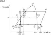
- Fig. 5 is a Mollier diagram showing a change in the state of the non-azeotropic refrigerant mixture in the cooling mode.
- the process from the state at node N9 to the state at node N1 represents the adiabatic compression process by compressor 1.
- the process from the state at node N1 to the state at node N7 (N6) represents the condensation process by outdoor heat exchanger 6.
- the process from the state at node N7 (N6) to the state at node N5 represents a decompression process by expansion valve 4B.
- the state at node N4 represents the state of the saturated liquid flowing out of receiver 5 and is shown on saturated liquid line LC in Fig. 5 .
- the process from the state at node N4 to the state at node N3 represents a decompression process by expansion valve 4A.
- the state at node N10 represents the state of the saturated vapor flowing out of receiver 5 and is shown on saturated vapor line GC in Fig. 5 .
- the process from the state at node N10 to the state at node N11 represents the cooling process by internal heat exchanger 7.
- the process from the state at node N11 to the state at node N12 represents the decompression process by expansion valve 4C.
- An enthalpy h11 in the state at node N12 is smaller than an enthalpy h13 in the state at node N3.
- an enthalpy h12 in the state at node N2 at which the non-azeotropic refrigerant mixture in the state at node N12 merges into the non-azeotropic refrigerant mixture in the state at node N3 is larger than enthalpy h11 and smaller than enthalpy h13. Note that enthalpy h12 is determined by the ratio between flow rates Q12 and Q13.
- the process from the state at node N2 to the state at node N8 represents the evaporation process by indoor heat exchanger 3.
- the non-azeotropic refrigerant mixture passing through internal heat exchanger 7 absorbs heat from the non-azeotropic refrigerant mixture in the state between the state at node N10 and the state at node N11.
- an enthalpy h16 in the state at node N9 is larger than an enthalpy h15 in the state at node N8.
- enthalpy h12 of the non-azeotropic refrigerant mixture flowing into indoor heat exchanger 3 functioning as an evaporator in the cooling mode is smaller, by cooling with internal heat exchanger 7, than enthalpy h13 of the non-azeotropic refrigerant mixture flowing out of expansion valve 4A.
- enthalpy h16 of the non-azeotropic refrigerant mixture suctioned into compressor 1 is larger, by heating with internal heat exchanger 7, than enthalpy h15 of the non-azeotropic refrigerant mixture flowing out of indoor heat exchanger 3.
- the difference between the enthalpy of the non-azeotropic refrigerant mixture flowing into indoor heat exchanger 3 and the enthalpy of the non-azeotropic refrigerant mixture suctioned into compressor 1 can be increased as compared with the case where the non-azeotropic refrigerant mixture in the state at node N3 flows into indoor heat exchanger 3 and the non-azeotropic refrigerant mixture in the state at node N8 is suctioned into compressor 1.
- the efficiency of refrigeration cycle apparatus 100 in the cooling mode can be improved.
- check valves 8A and 8B can suppress the performance deterioration of refrigeration cycle apparatus 100 resulting from a change in the composition ratio of the non-azeotropic refrigerant mixture both in the heating mode and the cooling mode. Further, according to refrigeration cycle apparatus 100, since check valves 8A and 8B each do not include a coil, the manufacturing cost and the power consumption of the refrigeration cycle apparatus can be suppressed as compared with the configuration in which the flow path into which the non-azeotropic refrigerant mixture flowing out of expansion valve 4C merges is switched according to the operation mode by a switching valve including a coil like a three-way valve.
- Fig. 6 is a flowchart showing a flow of a control process performed for expansion valves 4A to 4C by controller 10 in Figs. 1 and 4 .
- the process shown in Fig. 6 is invoked at each sampling time by a main routine (not shown).
- the degree of opening of each of expansion valves 4A to 4C is set at an initial value when the operation mode is started.
- a step will be simply abbreviated as S.
- controller 10 determines whether or not discharge temperature Td is equal to or higher than a temperature Tmin and is equal to or lower than a temperature Tmax (> Tmin).
- Temperature Tmin the minimum value in the second reference range
- temperature Tmax the maximum value in the second reference range
- controller 10 When discharge temperature Td is lower than temperature Tmin or is higher than temperature Tmax (NO in S 100), then in S 110, controller 10 performs the process of setting the degree of opening of the specific expansion valve that receives the non-azeotropic refrigerant mixture from receiver 5, and then, returns the process to the main routine.
- the specific expansion valve in S110 is expansion valve 4B in the heating mode and expansion valve 4A in the cooling mode.
- controller 10 When discharge temperature Td is equal to or higher than temperature Tmin and is equal to or lower than temperature Tmax (YES in S100), then in S120, controller 10 performs the process of setting the degree of opening of expansion valve 4C that receives the non-azeotropic refrigerant mixture from internal heat exchanger 7, and thereafter, returns the process to the main routine.
- the specific process flow in S120 will be described in the second and third embodiments.
- Fig. 7 is a flowchart showing a specific process flow of a process of setting the degree of opening of the specific expansion valve that receives the non-azeotropic refrigerant mixture from receiver 5, as shown in Fig. 6 .
- controller 10 determines whether or not discharge temperature Td is higher than temperature Tmax. When discharge temperature Td is higher than temperature Tmax (YES in S111), then in S112, controller 10 increases the degree of opening of the specific expansion valve by a predetermined degree of opening, and returns the process to the main routine.
- controller 10 decreases the degree of opening of the specific expansion valve by a predetermined degree of opening, and returns the process to the main routine.
- expansion valves 4A and 4B are controlled such that discharge temperature Td falls within a desired range, and thereby, the stability of refrigeration cycle apparatus 100 can be improved.
- the manufacturing cost and the power consumption of the refrigeration cycle apparatus can be reduced while preventing a performance deterioration of the refrigeration cycle apparatus resulting from a change in the composition ratio of the non-azeotropic refrigerant mixture.
- the stability of the refrigeration cycle apparatus can be improved.
- the second embodiment will be hereinafter described with regard to a configuration for determining the degree of opening of the third expansion valve based on the degree of supercooling of the non-azeotropic refrigerant mixture flowing out of a heat exchanger functioning as an evaporator and the pressure inside the refrigerant container.
- Fig. 8 is a diagram showing a functional configuration of a refrigeration cycle apparatus 200 according to the second embodiment.
- Refrigeration cycle apparatus 200 has a configuration in which refrigeration cycle apparatus 100 shown in Fig. 1 is additionally provided with temperature sensors 14, 15, 16, and 17 and a pressure sensor 18, and also provided with a controller 20 in place of controller 10.
- the other configurations of refrigeration cycle apparatus 200 are the same as those of refrigeration cycle apparatus 100, and therefore, the description of the same configurations as those of refrigeration cycle apparatus 100 will not be repeated.
- temperature sensor 14 outputs, to controller 20, a temperature T1 (the first temperature) of the non-azeotropic refrigerant mixture passing through indoor heat exchanger 3.
- Temperature sensor 15 outputs, to controller 20, a temperature T2 (the second temperature) of the non-azeotropic refrigerant mixture flowing between indoor heat exchanger 3 and node N2.
- Temperature sensor 16 outputs, to controller 20, a temperature T3 (the first temperature) of the non-azeotropic refrigerant mixture flowing through outdoor heat exchanger 6.
- Temperature sensor 17 outputs, to controller 20, a temperature T4 (the second temperature) of the non-azeotropic refrigerant mixture flowing between outdoor heat exchanger 6 and node N7.
- Pressure sensor 18 outputs pressure P1 inside receiver 5 to controller 20.
- temperature T1 is a temperature of the non-azeotropic refrigerant mixture in the condensation process between saturated vapor line GC and saturated liquid line LC.
- Temperature T2 is a temperature of the non-azeotropic refrigerant mixture in the state at node N2 (N3).
- the degree of opening of expansion valve 4C is determined according to the degree of dryness of the moist vapor (the non-azeotropic refrigerant mixture in the state at node N4) flowing into receiver 5.
- the degree of dryness is calculated from pressure P1 and enthalpy h4 in the state at node N2.
- Enthalpy h4 is calculated from a degree of supercooling Sc1.
- Degree of supercooling Sc1 is calculated from temperatures T1 and T2.
- temperature T3 is a temperature of the non-azeotropic refrigerant mixture in the condensation process between saturated vapor line GC and saturated liquid line LC.
- Temperature T4 is a temperature of the non-azeotropic refrigerant mixture in the state at node N7 (N6).
- the degree of opening of expansion valve 4C is determined according to the degree of dryness of the moist vapor (the non-azeotropic refrigerant mixture in the state at node N5) flowing into receiver 5.
- the degree of dryness is calculated from pressure P1 and enthalpy h14 in the state at node N7.
- Enthalpy h14 is calculated from a degree of supercooling Sc2.
- Degree of supercooling Sc2 is calculated from temperatures T3 and T4.
- Fig. 9 is a flowchart showing a specific process flow of the process of setting the degree of opening of expansion valve 4C that receives a non-azeotropic refrigerant mixture from internal heat exchanger 7, as shown in Fig. 6 .
- controller 20 calculates a degree of dryness Dr of the non-azeotropic refrigerant mixture that flows into receiver 5 based on pressure P1 and the degree of supercooling (Sc1 or Sc2) of the non-azeotropic refrigerant mixture that flows out of the specific heat exchanger functioning as a condenser, and then proceeds the process to S222.
- the specific heat exchanger in the heating mode is indoor heat exchanger 3 while the specific heat exchanger in the cooling mode is outdoor heat exchanger 6.
- Controller 20 calculates the degree of supercooling Sc1 from temperatures T1 and T2 in the heating mode, and calculates the degree of supercooling Sc2 from temperatures T3 and T4 in the cooling mode.
- controller 20 determines whether or not the degree of dryness Dr is equal to or higher than a degree of dryness Dmin and equal to or lower than a degree of dryness Dmax (> Dmin). When the degree of dryness Dr is equal to or higher than the degree of dryness Dmin and equal to or lower than the degree of dryness Dmax (YES in S222), controller 20 determines that the degree of dryness Dr falls within a desired range (the first reference range), and then, returns the process to the main routine. Note that the degrees of dryness Dmin and Dmax can be determined as appropriate by experiments on an actual machine or by simulations.
- controller 20 determines whether or not the degree of dryness Dr is higher than the degree of dryness Dmax.
- controller 20 increases the degree of opening of expansion valve 4C by a predetermined amount in order to decrease the gas refrigerant inside receiver 5, and then, returns the process to the main routine.
- controller 20 decreases the degree of opening of expansion valve 4C by a predetermined amount in order to increase the gas refrigerant inside receiver 5, and then, returns the process to the main routine.
- refrigeration cycle apparatus 200 since the degree of opening of expansion valve 4C is controlled according to the state of the non-azeotropic refrigerant mixture inside receiver 5, a performance deterioration of the refrigeration cycle apparatus resulting from a change in the composition ratio of the non-azeotropic refrigerant mixture can be further suppressed as compared with the case of refrigeration cycle apparatus 100.
- the manufacturing cost and the power consumption of the refrigeration cycle apparatus can be reduced while further suppressing the performance deterioration of the refrigeration cycle apparatus resulting from a change in the composition ratio of the non-azeotropic refrigerant mixture as compared with the case of the refrigeration cycle apparatus of the first embodiment. Further, according to the refrigeration cycle apparatus of the second embodiment, the stability of the refrigeration cycle apparatus can be improved.
- the third embodiment will be hereinafter described with regard to a configuration for determining the degree of opening of the third expansion valve based on the temperature of the gas refrigerant flowing out of the refrigerant container and the temperature of the liquid refrigerant flowing out of the refrigerant container.
- Fig. 10 is a diagram showing a functional configuration of a refrigeration cycle apparatus 300 according to the third embodiment.
- Refrigeration cycle apparatus 300 has a configuration in which refrigeration cycle apparatus 100 shown in Fig. 1 is additionally provided with temperature sensors 31 to 33 and also provided with a controller 30 in place of controller 10.
- the other configurations of refrigeration cycle apparatus 300 are the same as those of refrigeration cycle apparatus 100, and therefore, the description of the same configurations as those of refrigeration cycle apparatus 100 will not be repeated.
- Temperature sensor 31 outputs, to controller 30, a temperature Tq1 (the second temperature) of the non-azeotropic refrigerant mixture flowing between node N4 and receiver 5.
- Temperature sensor 32 outputs, to controller 30, a temperature Tq2 (the second temperature) of the non-azeotropic refrigerant mixture flowing between node N5 and receiver 5.
- Temperature sensor 33 outputs, to controller 30, a temperature Tg (the first temperature) of the gas refrigerant flowing out of receiver 5.
- Tq the temperature of the non-azeotropic refrigerant mixture flowing out of receiver 5 to expansion valve 4A or 4B is denoted as Tq.
- temperature Tq is temperature Tq2 in the heating mode and temperature Tq1 in the cooling mode.
- Fig. 11 is a flowchart showing a specific process flow of the process of setting the degree of opening of expansion valve 4C that receives the non-azeotropic refrigerant mixture from internal heat exchanger 7, as shown in Fig. 6 .
- time t represents the current sampling time
- time t-1 represents the previous sampling time.
- controller 30 determines whether or not the absolute value of the difference between the current temperature difference (Tg(t) - Tq(t)) and temperature gradient Tgd is smaller than threshold value ⁇ .
- controller 30 proceeds the process to S327.
- controller 30 changes the degree of opening of expansion valve 4C by a predetermined amount, and then proceeds the process to S327.
- the degree of opening of expansion valve 4C may be changed to be increased or decreased.
- controller 30 determines that the amount of moist vapor flowing out of receiver 5 per unit time has increased by the previous change of the degree of opening of expansion valve 4C, then in S325, controller 30 changes the degree of opening by a predetermined amount such that the change to increase or decrease the degree of opening of expansion valve 4C at this time is opposite to the previous change to increase or decrease the degree of opening, and then, proceeds the process to S327.
- the degree of opening of expansion valve 4C is increased in the previous process of setting the degree of opening, the degree of opening of expansion valve 4C is decreased in S325.
- the degree of opening of expansion valve 4C is decreased in the previous process of setting the degree of opening, the degree of opening of expansion valve 4C is increased in S325.
- controller 30 determines that the amount of moist vapor that flows out of receiver 5 per unit time has decreased by the previous change of the degree of opening of expansion valve 4C, then in S326, controller 30 changes the degree of opening by a predetermined amount such that the change to increase or decrease the degree of opening of expansion valve 4C at this time is the same as the previous change to increase or decrease the degree of opening, and then, proceeds the process to S327.
- the degree of opening of expansion valve 4C is increased in the previous process of setting the degree of opening, the degree of opening of expansion valve 4C is increased in S326.
- the degree of opening of expansion valve 4C is decreased in the previous process of setting the degree of opening, the degree of opening of expansion valve 4C is decreased in S326.
- controller 30 assigns current temperatures Tg(t) and Tq(t) to previous temperatures Tg(t-1) and Tq(t-1), respectively, and returns the process to the main routine.
- the degree of opening of expansion valve 4C is controlled in accordance with the state of the non-azeotropic refrigerant mixture inside receiver 5, and thereby, the performance deterioration of the refrigeration cycle apparatus resulting from the change in the composition ratio of the non-azeotropic refrigerant mixture can be further suppressed as compared with the case of refrigeration cycle apparatus 100. Further, according to refrigeration cycle apparatus 300, since the number of temperature sensors required for the process of setting the degree of opening of expansion valve 4C can be reduced to three and the pressure sensor is not required for the setting process, the manufacturing cost can be reduced as compared with the case of refrigeration cycle apparatus 200 that requires four temperature sensors and one pressure sensor for the setting process.
- the manufacturing cost and the power consumption of the refrigeration cycle apparatus can be reduced while further suppressing the performance deterioration of the refrigeration cycle apparatus resulting from the change in the composition ratio of the non-azeotropic refrigerant mixture as compared with the case of the refrigeration cycle apparatus of the first embodiment.
- the stability of the refrigeration cycle apparatus can be improved.
- the manufacturing cost can be reduced as compared with the case of the refrigeration cycle apparatus of the second embodiment.
Abstract
A refrigeration cycle apparatus (100) includes a compressor (1), a first heat exchanger (3), a second heat exchanger (6), a third heat exchanger (7), a flow path switching valve (2), a first expansion valve (4A), a second expansion valve (4B), a third expansion valve (4C), a refrigerant container (5), a first check valve (8A), and a second check valve (8B). The flow path switching valve (2) switches a circulation direction of a non-azeotropic refrigerant mixture between a first circulation direction and a second circulation direction. A first port (Pt1) of the third expansion valve (4C) communicates with the refrigerant container (5) through the third heat exchanger (7). A second port (Pt2) of the third expansion valve (4C) communicates through the first check valve (8A) with a first flow path (FP1) between the first heat exchanger (3) and the first expansion valve (4A), and communicates through the second check valve (8B) with a second flow path (FP2) between the second heat exchanger (6) and the second expansion valve (4B).
Description
- The present disclosure relates to a refrigeration cycle apparatus through which a non-azeotropic refrigerant mixture circulates.
- A refrigeration cycle apparatus through which a non-azeotropic refrigerant mixture circulates has conventionally been known. For example, International Publication No.
WO 2020/003494 (PTL 1) discloses a refrigeration cycle apparatus through which a non-azeotropic refrigerant mixture containing R32, CF3I, and R1123 circulates. In the refrigeration cycle apparatus, when the temperature gradient of the non-azeotropic refrigerant mixture exceeds a threshold value, R1123 having the lowest boiling point among R32, CF3I, and R1123 is returned from a refrigerant container to the non-azeotropic refrigerant mixture (circulating refrigerant) circulating through the refrigeration cycle apparatus, to thereby suppress an increase in temperature gradient and an increase in pressure loss ratio. This consequently can suppress the performance deterioration of the refrigeration cycle apparatus resulting from a decrease in the weight ratio of R1123 in the circulating refrigerant. - PTL 1: International Publication No.
WO 2020/003494 - In the refrigeration cycle apparatus disclosed in
PTL 1, the circulation direction of the non-azeotropic refrigerant mixture in a heating mode is opposite to the circulation direction of the non-azeotropic refrigerant mixture in a cooling mode. Thus, the route of the circulation path of the non-azeotropic refrigerant mixture through which R1123 is returned from the refrigerant container is switched by a three-way valve in accordance with the circulation direction of the non-azeotropic refrigerant mixture. However, the three-way valve that often includes a coil tends to be increased in cost and also tends to be increased in power consumption. - The present disclosure has been made in order to solve the above-described problems, and an object of the present disclosure is to, in a refrigeration cycle apparatus in which a circulation direction of a non-azeotropic refrigerant mixture is switched according to an operation mode, reduce the manufacturing cost and the power consumption of the refrigeration cycle apparatus while suppressing a performance deterioration of the refrigeration cycle apparatus resulting from a change in the composition ratio of the non-azeotropic refrigerant mixture.
- In a refrigeration cycle apparatus according to the present disclosure, a non-azeotropic refrigerant mixture circulates. The refrigeration cycle apparatus includes a compressor, a first heat exchanger, a second heat exchanger, a third heat exchanger, a flow path switching valve, a first expansion valve, a second expansion valve, a third expansion valve, a refrigerant container, a first check valve, and a second check valve. The flow path switching valve is configured to switch a circulation direction of the non-azeotropic refrigerant mixture between a first circulation direction and a second circulation direction. The third expansion valve includes a first port and a second port. In the first circulation direction, the non-azeotropic refrigerant mixture circulates in order of the compressor, the flow path switching valve, the first heat exchanger, the first expansion valve, the refrigerant container, the second expansion valve, the second heat exchanger, the flow path switching valve, and the third heat exchanger. In the second circulation direction, the non-azeotropic refrigerant mixture circulates in order of the compressor, the flow path switching valve, the second heat exchanger, the second expansion valve, the refrigerant container, the first expansion valve, the first heat exchanger, the flow path switching valve, and the third heat exchanger. The first port communicates with the refrigerant container through the third heat exchanger. The second port communicates through the first check valve with a first flow path between the first heat exchanger and the first expansion valve, and communicates through the second check valve with a second flow path between the second heat exchanger and the second expansion valve.
- According to the refrigeration cycle apparatus of the present disclosure, the second port of the third expansion valve communicates through the first check valve with the first flow path between the first heat exchanger and the first expansion valve and also communicates through the second check valve with the second flow path between the second heat exchanger and the second expansion valve. Thereby, in the refrigeration cycle apparatus in which the circulation direction of the non-azeotropic refrigerant mixture is switched according to the operation mode, the manufacturing cost and the power consumption of the refrigeration cycle apparatus can be reduced while suppressing the performance deterioration of the refrigeration cycle apparatus resulting from a change in the composition ratio of the non-azeotropic refrigerant mixture.
-
-
Fig. 1 is a diagram showing a functional configuration of a refrigeration cycle apparatus according to a first embodiment. -
Fig. 2 is a diagram showing a hardware configuration of a controller inFig. 1 . -
Fig. 3 is a Mollier diagram showing a change in the state of a non-azeotropic refrigerant mixture in a heating mode. -
Fig. 4 is a diagram showing the functional configuration of the refrigeration cycle apparatus according to the first embodiment together with a flow of the non-azeotropic refrigerant mixture in a cooling mode. -
Fig. 5 is a Mollier diagram showing a change in the state of a non-azeotropic refrigerant mixture in the cooling mode. -
Fig. 6 is a flowchart showing a flow of a control process performed for an expansion valve by the controller inFigs. 1 and4 . -
Fig. 7 is a flowchart showing a specific process flow of a process of setting a degree of opening of a specific expansion valve that receives a non-azeotropic refrigerant mixture from a receiver, as shown inFig. 6 . -
Fig. 8 is a diagram showing a functional configuration of a refrigeration cycle apparatus according to a second embodiment. -
Fig. 9 is a flowchart showing a specific process flow of the process of setting the degree of opening of the expansion valve that receives a non-azeotropic refrigerant mixture from an internal heat exchanger, as shown inFig. 6 . -
Fig. 10 is a diagram showing a functional configuration of a refrigeration cycle apparatus according to a third embodiment. -
Fig. 11 is a flowchart showing a specific process flow of the process of setting the degree of opening of the expansion valve that receives a non-azeotropic refrigerant mixture from an internal heat exchanger, as shown inFig. 6 . - Embodiments of the present disclosure will be hereinafter described in detail with reference to the accompanying drawings, in which the same or corresponding components are denoted by the same reference characters, and the description thereof will not be basically repeated.
-
Fig. 1 is a diagram showing a functional configuration of arefrigeration cycle apparatus 100 according to the first embodiment. Inrefrigeration cycle apparatus 100, a non-azeotropic refrigerant mixture circulates therethrough.Refrigeration cycle apparatus 100 operates in operation modes including a heating mode and a cooling mode.Fig. 1 shows the flow of the non-azeotropic refrigerant mixture in the heating mode.Refrigeration cycle apparatus 100 may be a package air conditioner (PAC), for example. - As shown in
Fig. 1 ,refrigeration cycle apparatus 100 includes anindoor unit 110 and anoutdoor unit 120.Indoor unit 110 includes an indoor heat exchanger 3 (a first heat exchanger).Outdoor unit 120 includes acompressor 1, a four-way valve 2 (a flow path switching valve), anexpansion valve 4A (a first expansion valve), anexpansion valve 4B (a second expansion valve), anexpansion valve 4C (a third expansion valve), a receiver 5 (a refrigerant container), an outdoor heat exchanger 6 (a second heat exchanger), an internal heat exchanger 7 (a third heat exchanger), acheck valve 8A (a first check valve), acheck valve 8B (a second check valve), acontroller 10, and atemperature sensor 13. Althoughcontroller 10 is included inoutdoor unit 120 inFig. 1 ,controller 10 may be included inindoor unit 110 or may be disposed outside each ofindoor unit 110 andoutdoor unit 120. - In
refrigeration cycle apparatus 100, a non-azeotropic refrigerant mixture or R463A is used, for example, that is reduced in GWP by mixing R32, CF3I, and R1123 into this non-azeotropic refrigerant mixture. The boiling points of R32, CF3I, and R1123 are -52°C, -22.5°C, and -56°C, respectively. R1123 raises the operating pressure of the non-azeotropic refrigerant mixture. R1123 is contained in the non-azeotropic refrigerant mixture to thereby allow reduction of the volume (stroke volume) ofcompressor 1 that is required for ensuring desired operating pressure, with the result thatcompressor 1 can be reduced in size. In addition, the non-azeotropic refrigerant mixture may include refrigerant other than R32, CF3I, and R1123 (for example, may include R1234yf, R1234ze(E), R290, or CO2). - Four-
way valve 2 switches the circulation direction of the non-azeotropic refrigerant mixture between the circulation direction in the heating mode (the first circulation direction) and the circulation direction in the cooling mode (the second circulation direction). In the heating mode, four-way valve 2 allows communication between a discharge port ofcompressor 1 and indoor heat exchanger 3, and allows communication betweenoutdoor heat exchanger 6 and a suction port ofcompressor 1. As a result, in the heating mode, the non-azeotropic refrigerant mixture circulates in order ofcompressor 1, four-way valve 2, indoor heat exchanger 3,expansion valve 4A, receiver 5,expansion valve 4B,outdoor heat exchanger 6, four-way valve 2, andinternal heat exchanger 7. -
Expansion valve 4C includes a port Pt1 (a first port) and a port Pt2 (a second port). Port Pt1 communicates with receiver 5 throughinternal heat exchanger 7. Port Pt2 communicates throughcheck valve 8A with a flow path FP1 (a first flow path) between indoor heat exchanger 3 and expansion valve 4A. Port Pt2 communicates throughcheck valve 8B with a flow path FP2 (a second flow path) betweenoutdoor heat exchanger 6 andexpansion valve 4B. -
Check valve 8A includes an input port Pt3 and an output port Pt4. Input port Pt3 communicates with port Pt2. Output port Pt4 communicates with flow path FP1. The forward direction ofcheck valve 8A corresponds to the direction from input port Pt3 to output port Pt4. - Check
valve 8B includes an input port Pt5 and an output port Pt6. Input port Pt5 communicates with port Pt2. Output port Pt6 communicates with flow path FP2. The forward direction ofcheck valve 8B corresponds to the direction from input port Pt5 to output port Pt6. - The non-azeotropic refrigerant mixture from
expansion valve 4A is guided through a pipe Pp1 to receiver 5. A non-azeotropic refrigerant mixture (moist vapor) in a gas-liquid two-phase state flows into receiver 5. The non-azeotropic refrigerant mixture flowing into receiver 5 is separated inside receiver 5 into a non-azeotropic refrigerant mixture in a liquid state (liquid refrigerant) and a non-azeotropic refrigerant mixture in a gas state (gas refrigerant). Among the plurality of types of refrigerant contained in the non-azeotropic refrigerant mixture, the refrigerant having a lower boiling point is higher in weight ratio in the gas refrigerant. - The liquid refrigerant inside receiver 5 is guided through a pipe Pp2 to
expansion valve 4B. The gas refrigerant inside receiver 5 is guided through a pipe Pp3 tointernal heat exchanger 7. In a gravity direction Gd, an end En3 of pipe Pp3 inside receiver 5 is located higher than an end En1 of pipe Pp1 inside receiver 5 and an end En2 of pipe Pp2 inside receiver 5. The non-azeotropic refrigerant mixture from the heat exchanger (outdoor heat exchanger 6 in the heating mode) functioning as an evaporator is heated ininternal heat exchanger 7 by the gas refrigerant guided through pipe Pp3 tointernal heat exchanger 7. - The gas refrigerant guided through pipe Pp3 to
internal heat exchanger 7 is guided throughexpansion valve 4C andcheck valve 8B tooutdoor heat exchanger 6. The pressure of the non-azeotropic refrigerant mixture flowing out ofexpansion valve 4C is lower than the pressure of the non-azeotropic refrigerant mixture flowing out of indoor heat exchanger 3, and is substantially the same as the pressure of the non-azeotropic refrigerant mixture flowing out ofexpansion valve 4B. Thus, the non-azeotropic refrigerant mixture flowing out ofexpansion valve 4C is directed not to checkvalve 8A but to checkvalve 8B. - Assuming that the flow rate of the moist vapor flowing through pipe Pp1 into receiver 5 per unit time is defined as Q1 (kg/hr), the flow rate of the liquid refrigerant flowing out of receiver 5 through pipe Pp2 per unit time is defined as Q2 (kg/hr), and the flow rate of the gas refrigerant flowing out of receiver 5 through pipe Pp3 per unit time is defined as Q3 (kg/hr), the condition Q1 = Q2 + Q3 is satisfied. Flow rate Q1 is determined by the driving frequency of
compressor 1 or the density of the non-azeotropic refrigerant mixture suctioned intocompressor 1. Flow rates Q2 and Q3 are respectively determined by the degrees of opening ofexpansion valves - The degree of opening of
expansion valve 4B is adjusted such that a discharge temperature Td falls within a desired range (a second reference range). The degree of opening ofexpansion valve 4B may be adjusted such that the degree of superheating of the non-azeotropic refrigerant mixture suctioned intocompressor 1 falls within a desired range. - Since the liquid refrigerant having flow rate Q2 and the gas refrigerant having flow rate Q3 that separately flow out of receiver 5 merge into flow path FP2, the non-azeotropic refrigerant mixture having flow rate Q1 flows into
outdoor heat exchanger 6. Inrefrigeration cycle apparatus 100, the composition ratio of the non-azeotropic refrigerant mixture that flows into receiver 5 can be maintained also in the non-azeotropic refrigerant mixture that flows into the heat exchanger functioning as an evaporator. According torefrigeration cycle apparatus 100, the refrigerant having a relatively low boiling point among the plurality of types of refrigerant included in the non-azeotropic refrigerant mixture stays in receiver 5, to thereby suppress a change in the composition ratio of the non-azeotropic refrigerant mixture circulating throughrefrigeration cycle apparatus 100, with the result that the performance deterioration ofrefrigeration cycle apparatus 100 resulting from a change in the composition ratio can be suppressed. -
Controller 10 controls the driving frequency ofcompressor 1 to thereby control the amount of refrigerant to be discharged fromcompressor 1 per unit time such that the temperature insideindoor unit 120 acquired by a temperature sensor (not shown) reaches a desired temperature (for example, a temperature set by a user).Controller 10 controls four-way valve 2 to switch the circulation direction of the non-azeotropic refrigerant mixture.Controller 10 controls the degrees of opening ofexpansion valves compressor 1 falls within a desired range.Temperature sensor 13 outputs, tocontroller 10, discharge temperature Td of the non-azeotropic refrigerant mixture discharged fromcompressor 1. - Nodes N1 to N12 are included in a flow path through which the non-azeotropic refrigerant mixture passes in
refrigeration cycle apparatus 100. Node N1 is a node through which the non-azeotropic refrigerant mixture flowing between the discharge port ofcompressor 1 and four-way valve 2 passes. Nodes N2 and N3 are included in flow path FP1.Check valve 8A communicates with flow path FP1 at node N2. Node N3 is a node through which the non-azeotropic refrigerant mixture flowing between node N2 andexpansion valve 4A passes. Node N4 is a node through which the non-azeotropic refrigerant mixture flowing betweenexpansion valve 4A and receiver 5 passes. - Node N5 is a node through which the non-azeotropic refrigerant mixture flowing between receiver 5 and
expansion valve 4B passes. Nodes N6 and N7 are included in flow path FP2. Checkvalve 8B communicates with flow path FP2 at node N7. Node N6 is a node through which the non-azeotropic refrigerant mixture flowing betweenexpansion valve 4B and node N7 passes. Node N8 is a node through which the non-azeotropic refrigerant mixture flowing between four-way valve 2 andinternal heat exchanger 7 passes. Node N9 is a node through which the non-azeotropic refrigerant mixture flowing betweeninternal heat exchanger 7 and the suction port ofcompressor 1 passes. - Node N10 is a node through which the non-azeotropic refrigerant mixture flowing between receiver 5 and
internal heat exchanger 7 passes. Node N11 is a node through which the non-azeotropic refrigerant mixture flowing betweeninternal heat exchanger 7 andexpansion valve 4C passes. Node N12 is a node through which the non-azeotropic refrigerant mixture flowing out ofexpansion valve 4C passes. -
Fig. 2 is a diagram showing a hardware configuration ofcontroller 10 inFig. 1 . Each ofcontrollers Fig. 2 . - As shown in
Fig. 2 ,controller 10 includescircuitry 91, amemory 92, and an input/output unit 93.Circuitry 91 may be dedicated hardware or a central processing unit (CPU) that executes a program stored inmemory 92. Whencircuitry 91 is dedicated hardware,circuitry 91 is, for example, a single circuit, a composite circuit, a programmed processor, a parallel programmed processor, an application specific integrated circuit (ASIC), a field programmable gate array (FPGA), or a combination thereof. Whencircuitry 91 is a CPU, the function ofcontroller 10 is implemented by software, firmware, or a combination of software and firmware. Software or firmware is described as a program and stored inmemory 92.Circuitry 91 reads and executes the program stored inmemory 92.Memory 92 includes a nonvolatile or volatile semiconductor memory (for example, a random access memory (RAM), a read only memory (ROM), a flash memory, an erasable programmable read only memory (EPROM), or an electrically erasable programmable read only memory (EEPROM)), a magnetic disk, a flexible disk, an optical disk, a compact disk, a mini disk, or a digital versatile disc (DVD). Note that the CPU is also referred to as a central processing unit, a processing unit, a computing unit, a microprocessor, a microcomputer, a processor, or a digital signal processor (DSP). - Input/
output unit 93 receives an operation from a user and outputs a process result to the user. Input/output unit 93 includes, for example, a mouse, a keyboard, a touch panel, a display, and a speaker. -
Fig. 3 is a Mollier diagram (a P-h diagram) showing a change in the state of a non-azeotropic refrigerant mixture in a heating mode. InFig. 3 , curved lines LC and GC represent a saturated liquid line and a saturated vapor line, respectively. Saturated liquid line LC and saturated vapor line GC are connected at a critical point CP. The states shown inFig. 3 correspond to the respective states of the non-azeotropic refrigerant mixture at nodes N1 to N12 inFig. 1 . The same also applies toFig. 5 , which will be described later. - Referring to both
Figs. 1 and3 , the process from the state at node N9 to the state at node N1 represents the adiabatic compression process bycompressor 1. The temperature of the non-azeotropic refrigerant mixture in the state at node N1 is measured as discharge temperature Td bytemperature sensor 13. The process from the state at node N1 to the state at node N2 (N3) represents the condensation process by indoor heat exchanger 3. In the condensation process between saturated vapor line GC and saturated liquid line LC (in the gas-liquid two-phase state), the temperature of the non-azeotropic refrigerant mixture decreases as the condensation process proceeds. - The process from the state at node N2 (N3) to the state at node N4 represents the decompression process by
expansion valve 4A. The state at node N5 represents the state of the saturated liquid flowing out of receiver 5 and is shown on saturated liquid line LC inFig. 3 . The process from the state at node N5 to the state at node N6 represents the decompression process byexpansion valve 4B. - The state at node N10 represents the state of the saturated vapor flowing out of receiver 5 and is shown on saturated vapor line GC in
Fig. 3 . The process from the state at node N10 to the state at node N11 represents a cooling process byinternal heat exchanger 7. The process from the state at node N11 to the state at node N12 represents the decompression process byexpansion valve 4C. An enthalpy h1 in the state at node N12 is smaller than an enthalpy h3 in the state at node N6. Thus, an enthalpy h2 in the state at node N7 at which the non-azeotropic refrigerant mixture in the state at node N12 merges into the non-azeotropic refrigerant mixture in the state at node N6 is larger than enthalpy h1 and smaller than enthalpy h3. Note that enthalpy h2 is determined by the ratio between flow rates Q2 and Q3. - The process from the state at node N7 to the state at node N8 represents the evaporation process by
outdoor heat exchanger 6. In the evaporation process (in the gas-liquid two-phase state) between saturated vapor line GC and saturated liquid line LC, the temperature of the non-azeotropic refrigerant mixture rises as the evaporation process proceeds. In the process from the state at node N8 to the state at node N9, the non-azeotropic refrigerant mixture that passes throughinternal heat exchanger 7 absorbs heat from the non-azeotropic refrigerant mixture in the state between the state at node N10 and the state at node N11. Thus, an enthalpy h6 in the state at node N9 is larger than an enthalpy h5 in the state at node N8. - In
refrigeration cycle apparatus 100, enthalpy h2 of the non-azeotropic refrigerant mixture that flows intooutdoor heat exchanger 6 functioning as an evaporator in the heating mode is smaller, by cooling withinternal heat exchanger 7, than enthalpy h3 of the non-azeotropic refrigerant mixture that flows out ofexpansion valve 4B. Further, enthalpy h6 of the non-azeotropic refrigerant mixture suctioned intocompressor 1 is larger, by heating withinternal heat exchanger 7, than enthalpy h5 of the non-azeotropic refrigerant mixture that flows out ofoutdoor heat exchanger 6. Thus, the difference between the enthalpy of the non-azeotropic refrigerant mixture flowing intooutdoor heat exchanger 6 and the enthalpy of the non-azeotropic refrigerant mixture suctioned intocompressor 1 can be increased as compared with the case where the non-azeotropic refrigerant mixture in the state at node N6 flows intooutdoor heat exchanger 6 and the non-azeotropic refrigerant mixture in the state at node N8 is suctioned intocompressor 1. As a result, the efficiency ofrefrigeration cycle apparatus 100 in the heating mode can be improved. -
Fig. 4 is a diagram showing the functional configuration ofrefrigeration cycle apparatus 100 according to the first embodiment together with the flow of the non-azeotropic refrigerant mixture in the cooling mode. In the cooling mode, four-way valve 2 allows communication between the discharge port ofcompressor 1 andoutdoor heat exchanger 6, and also allows communication between indoor heat exchanger 3 and the suction port ofcompressor 1. As a result, in the cooling mode, the non-azeotropic refrigerant mixture circulates in order ofcompressor 1, four-way valve 2,outdoor heat exchanger 6,expansion valve 4B, receiver 5,expansion valve 4A, indoor heat exchanger 3, four-way valve 2, andinternal heat exchanger 7. - The pressure of the non-azeotropic refrigerant mixture flowing out of
expansion valve 4C is lower than the pressure of the non-azeotropic refrigerant mixture flowing out ofoutdoor heat exchanger 6, and is substantially the same as the pressure of the non-azeotropic refrigerant mixture flowing out ofexpansion valve 4A. Thus, the non-azeotropic refrigerant mixture flowing out ofexpansion valve 4C is directed not to checkvalve 8B but to checkvalve 8A. - Assuming that the flow rate of the moist vapor flowing into receiver 5 through pipe Pp2 per unit time is defined as Q11 (kg/hr), the flow rate of the liquid refrigerant flowing out of receiver 5 through pipe Pp1 per unit time is defined as Q12 (kg/hr), and the flow rate of the gas refrigerant flowing out of receiver 5 through pipe Pp3 per unit time is defined as Q13 (kg/hr), the condition Q11 = Q12 + Q13 is satisfied. Flow rate Q11 is determined by the driving frequency of
compressor 1 or the density of the non-azeotropic refrigerant mixture suctioned intocompressor 1. Flow rates Q12 and Q13 are determined by the degrees of opening ofexpansion valves - In the cooling mode, the degree of opening of
expansion valve 4A is adjusted such that discharge temperature Td falls within a desired range (the second reference range). The degree of opening ofexpansion valve 4A may be adjusted such that the degree of superheating of the non-azeotropic refrigerant mixture suctioned intocompressor 1 falls within a desired range. -
Fig. 5 is a Mollier diagram showing a change in the state of the non-azeotropic refrigerant mixture in the cooling mode. Referring to bothFigs. 4 and5 , the process from the state at node N9 to the state at node N1 represents the adiabatic compression process bycompressor 1. The process from the state at node N1 to the state at node N7 (N6) represents the condensation process byoutdoor heat exchanger 6. - The process from the state at node N7 (N6) to the state at node N5 represents a decompression process by
expansion valve 4B. The state at node N4 represents the state of the saturated liquid flowing out of receiver 5 and is shown on saturated liquid line LC inFig. 5 . The process from the state at node N4 to the state at node N3 represents a decompression process byexpansion valve 4A. - The state at node N10 represents the state of the saturated vapor flowing out of receiver 5 and is shown on saturated vapor line GC in
Fig. 5 . The process from the state at node N10 to the state at node N11 represents the cooling process byinternal heat exchanger 7. The process from the state at node N11 to the state at node N12 represents the decompression process byexpansion valve 4C. An enthalpy h11 in the state at node N12 is smaller than an enthalpy h13 in the state at node N3. Thus, an enthalpy h12 in the state at node N2 at which the non-azeotropic refrigerant mixture in the state at node N12 merges into the non-azeotropic refrigerant mixture in the state at node N3 is larger than enthalpy h11 and smaller than enthalpy h13. Note that enthalpy h12 is determined by the ratio between flow rates Q12 and Q13. - The process from the state at node N2 to the state at node N8 represents the evaporation process by indoor heat exchanger 3. In the process from the state at node N8 to the state at node N9, the non-azeotropic refrigerant mixture passing through
internal heat exchanger 7 absorbs heat from the non-azeotropic refrigerant mixture in the state between the state at node N10 and the state at node N11. Thus, an enthalpy h16 in the state at node N9 is larger than an enthalpy h15 in the state at node N8. - In
refrigeration cycle apparatus 100, enthalpy h12 of the non-azeotropic refrigerant mixture flowing into indoor heat exchanger 3 functioning as an evaporator in the cooling mode is smaller, by cooling withinternal heat exchanger 7, than enthalpy h13 of the non-azeotropic refrigerant mixture flowing out ofexpansion valve 4A. Further, enthalpy h16 of the non-azeotropic refrigerant mixture suctioned intocompressor 1 is larger, by heating withinternal heat exchanger 7, than enthalpy h15 of the non-azeotropic refrigerant mixture flowing out of indoor heat exchanger 3. Thus, the difference between the enthalpy of the non-azeotropic refrigerant mixture flowing into indoor heat exchanger 3 and the enthalpy of the non-azeotropic refrigerant mixture suctioned intocompressor 1 can be increased as compared with the case where the non-azeotropic refrigerant mixture in the state at node N3 flows into indoor heat exchanger 3 and the non-azeotropic refrigerant mixture in the state at node N8 is suctioned intocompressor 1. As a result, the efficiency ofrefrigeration cycle apparatus 100 in the cooling mode can be improved. - According to
refrigeration cycle apparatus 100,check valves refrigeration cycle apparatus 100 resulting from a change in the composition ratio of the non-azeotropic refrigerant mixture both in the heating mode and the cooling mode. Further, according torefrigeration cycle apparatus 100, sincecheck valves expansion valve 4C merges is switched according to the operation mode by a switching valve including a coil like a three-way valve. -
Fig. 6 is a flowchart showing a flow of a control process performed forexpansion valves 4A to 4C bycontroller 10 inFigs. 1 and4 . The process shown inFig. 6 is invoked at each sampling time by a main routine (not shown). The degree of opening of each ofexpansion valves 4A to 4C is set at an initial value when the operation mode is started. In the following description, a step will be simply abbreviated as S. - As shown in
Fig. 6 , in S100,controller 10 determines whether or not discharge temperature Td is equal to or higher than a temperature Tmin and is equal to or lower than a temperature Tmax (> Tmin). Temperature Tmin (the minimum value in the second reference range) and temperature Tmax (the maximum value in the second reference range) can be determined as appropriate by experiments on an actual machine or by simulations. - When discharge temperature Td is lower than temperature Tmin or is higher than temperature Tmax (NO in S 100), then in
S 110,controller 10 performs the process of setting the degree of opening of the specific expansion valve that receives the non-azeotropic refrigerant mixture from receiver 5, and then, returns the process to the main routine. The specific expansion valve in S110 isexpansion valve 4B in the heating mode andexpansion valve 4A in the cooling mode. When discharge temperature Td is equal to or higher than temperature Tmin and is equal to or lower than temperature Tmax (YES in S100), then in S120,controller 10 performs the process of setting the degree of opening ofexpansion valve 4C that receives the non-azeotropic refrigerant mixture frominternal heat exchanger 7, and thereafter, returns the process to the main routine. The specific process flow in S120 will be described in the second and third embodiments. -
Fig. 7 is a flowchart showing a specific process flow of a process of setting the degree of opening of the specific expansion valve that receives the non-azeotropic refrigerant mixture from receiver 5, as shown inFig. 6 . As shown inFig. 7 , in S111,controller 10 determines whether or not discharge temperature Td is higher than temperature Tmax. When discharge temperature Td is higher than temperature Tmax (YES in S111), then in S112,controller 10 increases the degree of opening of the specific expansion valve by a predetermined degree of opening, and returns the process to the main routine. When discharge temperature Td is equal to or lower than temperature Tmax (lower than temperature Tmin) (NO in S111), then in S113,controller 10 decreases the degree of opening of the specific expansion valve by a predetermined degree of opening, and returns the process to the main routine. - In
refrigeration cycle apparatus 100,expansion valves refrigeration cycle apparatus 100 can be improved. - As described above, according to the refrigeration cycle apparatus in the first embodiment, in the refrigeration cycle apparatus in which the circulation direction of the non-azeotropic refrigerant mixture is switched according to the operation mode, the manufacturing cost and the power consumption of the refrigeration cycle apparatus can be reduced while preventing a performance deterioration of the refrigeration cycle apparatus resulting from a change in the composition ratio of the non-azeotropic refrigerant mixture. Further, according to the refrigeration cycle apparatus of the first embodiment, the stability of the refrigeration cycle apparatus can be improved.
- The second embodiment will be hereinafter described with regard to a configuration for determining the degree of opening of the third expansion valve based on the degree of supercooling of the non-azeotropic refrigerant mixture flowing out of a heat exchanger functioning as an evaporator and the pressure inside the refrigerant container.
-
Fig. 8 is a diagram showing a functional configuration of arefrigeration cycle apparatus 200 according to the second embodiment.Refrigeration cycle apparatus 200 has a configuration in whichrefrigeration cycle apparatus 100 shown inFig. 1 is additionally provided withtemperature sensors pressure sensor 18, and also provided with acontroller 20 in place ofcontroller 10. The other configurations ofrefrigeration cycle apparatus 200 are the same as those ofrefrigeration cycle apparatus 100, and therefore, the description of the same configurations as those ofrefrigeration cycle apparatus 100 will not be repeated. - As shown in
Fig. 8 ,temperature sensor 14 outputs, tocontroller 20, a temperature T1 (the first temperature) of the non-azeotropic refrigerant mixture passing through indoor heat exchanger 3. Temperature sensor 15 outputs, tocontroller 20, a temperature T2 (the second temperature) of the non-azeotropic refrigerant mixture flowing between indoor heat exchanger 3 and node N2.Temperature sensor 16 outputs, tocontroller 20, a temperature T3 (the first temperature) of the non-azeotropic refrigerant mixture flowing throughoutdoor heat exchanger 6. Temperature sensor 17 outputs, tocontroller 20, a temperature T4 (the second temperature) of the non-azeotropic refrigerant mixture flowing betweenoutdoor heat exchanger 6 and node N7.Pressure sensor 18 outputs pressure P1 inside receiver 5 tocontroller 20. - Referring again to
Fig. 3 , temperature T1 is a temperature of the non-azeotropic refrigerant mixture in the condensation process between saturated vapor line GC and saturated liquid line LC. Temperature T2 is a temperature of the non-azeotropic refrigerant mixture in the state at node N2 (N3). The degree of opening ofexpansion valve 4C is determined according to the degree of dryness of the moist vapor (the non-azeotropic refrigerant mixture in the state at node N4) flowing into receiver 5. The degree of dryness is calculated from pressure P1 and enthalpy h4 in the state at node N2. Enthalpy h4 is calculated from a degree of supercooling Sc1. Degree of supercooling Sc1 is calculated from temperatures T1 and T2. - Referring again to
Fig. 5 , temperature T3 is a temperature of the non-azeotropic refrigerant mixture in the condensation process between saturated vapor line GC and saturated liquid line LC. Temperature T4 is a temperature of the non-azeotropic refrigerant mixture in the state at node N7 (N6). The degree of opening ofexpansion valve 4C is determined according to the degree of dryness of the moist vapor (the non-azeotropic refrigerant mixture in the state at node N5) flowing into receiver 5. The degree of dryness is calculated from pressure P1 and enthalpy h14 in the state at node N7. Enthalpy h14 is calculated from a degree of supercooling Sc2. Degree of supercooling Sc2 is calculated from temperatures T3 and T4. -
Fig. 9 is a flowchart showing a specific process flow of the process of setting the degree of opening ofexpansion valve 4C that receives a non-azeotropic refrigerant mixture frominternal heat exchanger 7, as shown inFig. 6 . As shown inFig. 9 , in S221,controller 20 calculates a degree of dryness Dr of the non-azeotropic refrigerant mixture that flows into receiver 5 based on pressure P1 and the degree of supercooling (Sc1 or Sc2) of the non-azeotropic refrigerant mixture that flows out of the specific heat exchanger functioning as a condenser, and then proceeds the process to S222. The specific heat exchanger in the heating mode is indoor heat exchanger 3 while the specific heat exchanger in the cooling mode isoutdoor heat exchanger 6.Controller 20 calculates the degree of supercooling Sc1 from temperatures T1 and T2 in the heating mode, and calculates the degree of supercooling Sc2 from temperatures T3 and T4 in the cooling mode. - In S222,
controller 20 determines whether or not the degree of dryness Dr is equal to or higher than a degree of dryness Dmin and equal to or lower than a degree of dryness Dmax (> Dmin). When the degree of dryness Dr is equal to or higher than the degree of dryness Dmin and equal to or lower than the degree of dryness Dmax (YES in S222),controller 20 determines that the degree of dryness Dr falls within a desired range (the first reference range), and then, returns the process to the main routine. Note that the degrees of dryness Dmin and Dmax can be determined as appropriate by experiments on an actual machine or by simulations. - When the degree of dryness Dr is lower than the degree of dryness Dmin or is higher than the degree of dryness Dmax (NO in S222), then in S223,
controller 20 determines whether or not the degree of dryness Dr is higher than the degree of dryness Dmax. When the degree of dryness Dr is higher than the degree of dryness Dmax (YES in S223), then in S224,controller 20 increases the degree of opening ofexpansion valve 4C by a predetermined amount in order to decrease the gas refrigerant inside receiver 5, and then, returns the process to the main routine. When the degree of dryness Dr is equal to or lower than the degree of dryness Dmax (i.e., lower than the degree of dryness Dmin) (NO in S223), then in S225,controller 20 decreases the degree of opening ofexpansion valve 4C by a predetermined amount in order to increase the gas refrigerant inside receiver 5, and then, returns the process to the main routine. - According to
refrigeration cycle apparatus 200, since the degree of opening ofexpansion valve 4C is controlled according to the state of the non-azeotropic refrigerant mixture inside receiver 5, a performance deterioration of the refrigeration cycle apparatus resulting from a change in the composition ratio of the non-azeotropic refrigerant mixture can be further suppressed as compared with the case ofrefrigeration cycle apparatus 100. - As described above, according to the refrigeration cycle apparatus of the second embodiment, in the refrigeration cycle apparatus in which the circulation direction of the non-azeotropic refrigerant mixture is switched according to the operation mode, the manufacturing cost and the power consumption of the refrigeration cycle apparatus can be reduced while further suppressing the performance deterioration of the refrigeration cycle apparatus resulting from a change in the composition ratio of the non-azeotropic refrigerant mixture as compared with the case of the refrigeration cycle apparatus of the first embodiment. Further, according to the refrigeration cycle apparatus of the second embodiment, the stability of the refrigeration cycle apparatus can be improved.
- The third embodiment will be hereinafter described with regard to a configuration for determining the degree of opening of the third expansion valve based on the temperature of the gas refrigerant flowing out of the refrigerant container and the temperature of the liquid refrigerant flowing out of the refrigerant container.
-
Fig. 10 is a diagram showing a functional configuration of a refrigeration cycle apparatus 300 according to the third embodiment. Refrigeration cycle apparatus 300 has a configuration in whichrefrigeration cycle apparatus 100 shown inFig. 1 is additionally provided withtemperature sensors 31 to 33 and also provided with acontroller 30 in place ofcontroller 10. The other configurations of refrigeration cycle apparatus 300 are the same as those ofrefrigeration cycle apparatus 100, and therefore, the description of the same configurations as those ofrefrigeration cycle apparatus 100 will not be repeated. -
Temperature sensor 31 outputs, tocontroller 30, a temperature Tq1 (the second temperature) of the non-azeotropic refrigerant mixture flowing between node N4 and receiver 5.Temperature sensor 32 outputs, tocontroller 30, a temperature Tq2 (the second temperature) of the non-azeotropic refrigerant mixture flowing between node N5 and receiver 5. Temperature sensor 33 outputs, tocontroller 30, a temperature Tg (the first temperature) of the gas refrigerant flowing out of receiver 5. In the following description, the temperature of the non-azeotropic refrigerant mixture flowing out of receiver 5 toexpansion valve - When an absolute value (|{Tg - Tq} - Tgdl) of the difference between a temperature difference between temperatures Tg and Tq and a temperature difference (a temperature gradient) Tgd between the temperatures of the saturated vapor and the saturated liquid at the pressure of receiver 5 is smaller than a threshold value δ, and when the temperature difference is substantially equal to temperature gradient Tgd, the non-azeotropic refrigerant mixture of the saturated vapor flows out through pipe Pp3, and the saturated liquid flows out through pipe Pp2. In this case, the degree of opening of
expansion valve 4C is appropriate and therefore does not need to be changed. Temperature gradient Tgd can be calculated in advance by theoretical calculation. Further, threshold value δ can be determined as appropriate by experiments on an actual machine or by simulations. - On the other hand, when the absolute value of the difference between the temperature difference and temperature gradient Tgd is larger than threshold value δ, it is assumed that moist vapor flows out through at least one of pipes Pp2 and Pp3. In this case, the degree of opening of
expansion valve 4C needs to be adjusted in order to suppress the performance deterioration of refrigeration cycle apparatus 300. - In the situation conceivable when moist vapor flows out through pipe Pp2, the excessively small degree of opening of
expansion valve 4C decreases the amount of gas refrigerant flowing out of receiver 5 per unit time, and thus, receiver 5 is filled with gas refrigerant, so that liquid refrigerant becomes insufficient. In the situation conceivable when moist vapor flows out through pipe Pp3, the excessively large degree of opening ofexpansion valve 4C increases the amount of gas refrigerant flowing out of receiver 5 per unit time, and thus, receiver 5 is almost filled with liquid refrigerant, so that gas refrigerant becomes insufficient inside receiver 5. - Accordingly, in refrigeration cycle apparatus 300, it is determined whether adjustment of the degree of opening of
expansion valve 4C is required or not based on whether or not the difference between temperatures Tg and Tq is substantially equal to temperature gradient Tgd.Fig. 11 is a flowchart showing a specific process flow of the process of setting the degree of opening ofexpansion valve 4C that receives the non-azeotropic refrigerant mixture frominternal heat exchanger 7, as shown inFig. 6 . InFig. 11 , time t represents the current sampling time, and time t-1 represents the previous sampling time. - As shown in
Fig. 11 , in S321,controller 30 determines whether or not the absolute value of the difference between the current temperature difference (Tg(t) - Tq(t)) and temperature gradient Tgd is smaller than threshold value δ. When the absolute value is smaller than threshold value δ (YES in S321),controller 30 proceeds the process to S327. - When the absolute value is equal to or larger than threshold value δ (NO in S321), then in S322,
controller 30 determines whether the process of setting the degree of opening ofexpansion valve 4C is the first process (t = 1) or not. When the process of setting the degree of opening ofexpansion valve 4C is the first process (YES in S322), then in S323,controller 30 changes the degree of opening ofexpansion valve 4C by a predetermined amount, and then proceeds the process to S327. In step S323, the degree of opening ofexpansion valve 4C may be changed to be increased or decreased. When the process of setting the degree of opening ofexpansion valve 4C is not the first process (NO in S322), then in S324,controller 30 determines whether or not the current temperature difference is smaller than the previous temperature difference. - When the current temperature difference is smaller than the previous temperature difference (YES in S324),
controller 30 determines that the amount of moist vapor flowing out of receiver 5 per unit time has increased by the previous change of the degree of opening ofexpansion valve 4C, then in S325,controller 30 changes the degree of opening by a predetermined amount such that the change to increase or decrease the degree of opening ofexpansion valve 4C at this time is opposite to the previous change to increase or decrease the degree of opening, and then, proceeds the process to S327. When the degree of opening ofexpansion valve 4C is increased in the previous process of setting the degree of opening, the degree of opening ofexpansion valve 4C is decreased in S325. When the degree of opening ofexpansion valve 4C is decreased in the previous process of setting the degree of opening, the degree of opening ofexpansion valve 4C is increased in S325. - When the current temperature difference is equal to or larger than the previous temperature difference (NO in S324),
controller 30 determines that the amount of moist vapor that flows out of receiver 5 per unit time has decreased by the previous change of the degree of opening ofexpansion valve 4C, then in S326,controller 30 changes the degree of opening by a predetermined amount such that the change to increase or decrease the degree of opening ofexpansion valve 4C at this time is the same as the previous change to increase or decrease the degree of opening, and then, proceeds the process to S327. When the degree of opening ofexpansion valve 4C is increased in the previous process of setting the degree of opening, the degree of opening ofexpansion valve 4C is increased in S326. When the degree of opening ofexpansion valve 4C is decreased in the previous process of setting the degree of opening, the degree of opening ofexpansion valve 4C is decreased in S326. - In S327,
controller 30 assigns current temperatures Tg(t) and Tq(t) to previous temperatures Tg(t-1) and Tq(t-1), respectively, and returns the process to the main routine. - According to refrigeration cycle apparatus 300, the degree of opening of
expansion valve 4C is controlled in accordance with the state of the non-azeotropic refrigerant mixture inside receiver 5, and thereby, the performance deterioration of the refrigeration cycle apparatus resulting from the change in the composition ratio of the non-azeotropic refrigerant mixture can be further suppressed as compared with the case ofrefrigeration cycle apparatus 100. Further, according to refrigeration cycle apparatus 300, since the number of temperature sensors required for the process of setting the degree of opening ofexpansion valve 4C can be reduced to three and the pressure sensor is not required for the setting process, the manufacturing cost can be reduced as compared with the case ofrefrigeration cycle apparatus 200 that requires four temperature sensors and one pressure sensor for the setting process. - As described above, according to the refrigeration cycle apparatus of the third embodiment, in the refrigeration cycle apparatus in which the circulation direction of the non-azeotropic refrigerant mixture is switched according to the operation mode, the manufacturing cost and the power consumption of the refrigeration cycle apparatus can be reduced while further suppressing the performance deterioration of the refrigeration cycle apparatus resulting from the change in the composition ratio of the non-azeotropic refrigerant mixture as compared with the case of the refrigeration cycle apparatus of the first embodiment. Further, according to the refrigeration cycle apparatus of the third embodiment, the stability of the refrigeration cycle apparatus can be improved. Further, according to the refrigeration cycle apparatus of the third embodiment, the manufacturing cost can be reduced as compared with the case of the refrigeration cycle apparatus of the second embodiment.
- The embodiments disclosed herein are also intended to be implemented in combination as appropriate within a consistent scope. It should be understood that the embodiments disclosed herein are illustrative and non-restrictive in every respect. The scope of the present disclosure is defined by the terms of the claims, rather than the description above, and is intended to include any modifications within the meaning and scope equivalent to the terms of the claims.
- 1 compressor, 2 four-way valve, 3 indoor heat exchanger, 4A to 4C expansion valve, 5 receiver, 6 outdoor heat exchanger, 7 heat exchanger, 8A, 8B check valve, 10, 20, 30 controller, 13 to 17, 31 to 33 temperature sensor, 18 pressure sensor, 91 circuitry, 92 memory, 93 input/
output unit
Claims (4)
- A refrigeration cycle apparatus through which a non-azeotropic refrigerant mixture circulates, the refrigeration cycle apparatus comprising:a compressor;a first heat exchanger;a second heat exchanger;a third heat exchanger;a flow path switching valve configured to switch a circulation direction of the non-azeotropic refrigerant mixture between a first circulation direction and a second circulation direction;a first expansion valve;a second expansion valve;a third expansion valve having a first port and a second port;a refrigerant container;a first check valve; anda second check valve, whereinin the first circulation direction, the non-azeotropic refrigerant mixture circulates in order of the compressor, the flow path switching valve, the first heat exchanger, the first expansion valve, the refrigerant container, the second expansion valve, the second heat exchanger, the flow path switching valve, and the third heat exchanger,in the second circulation direction, the non-azeotropic refrigerant mixture circulates in order of the compressor, the flow path switching valve, the second heat exchanger, the second expansion valve, the refrigerant container, the first expansion valve, the first heat exchanger, the flow path switching valve, and the third heat exchanger,the first port communicates with the refrigerant container through the third heat exchanger, andthe second port communicates through the first check valve with a first flow path between the first heat exchanger and the first expansion valve, and communicates through the second check valve with a second flow path between the second heat exchanger and the second expansion valve.
- The refrigeration cycle apparatus according to claim 1, further comprising a controller configured to control a degree of opening of the third expansion valve, wherein
based on: a first temperature of the non-azeotropic refrigerant mixture inside a specific heat exchanger functioning as a condenser among the first heat exchanger and the second heat exchanger; a second temperature of the non-azeotropic refrigerant mixture that flows out of the specific heat exchanger; and pressure of the non-azeotropic refrigerant mixture inside the refrigerant container, the controller is configured to control the degree of opening of the third expansion valve such that a degree of dryness of the non-azeotropic refrigerant mixture inside the refrigerant container falls within a first reference range. - The refrigeration cycle apparatus according to claim 1, further comprising a controller configured to control a degree of opening of the third expansion valve, whereinbased on: a first temperature of the non-azeotropic refrigerant mixture that flows out of the refrigerant container into the third heat exchanger; and a second temperature of the non-azeotropic refrigerant mixture that flows out of the refrigerant container into the first expansion valve or the second expansion valve, the controller is configured to control the degree of opening of the third expansion valve such that a difference between the first temperature and the second temperature approaches a temperature gradient at pressure of the non-azeotropic refrigerant mixture inside the refrigerant container, andthe temperature gradient is a temperature difference between saturated vapor and saturated liquid of the non-azeotropic refrigerant mixture at the pressure.
- The refrigeration cycle apparatus according to claim 2 or 3, wherein
the controller is configured toincrease a degree of opening of a specific expansion valve which is the first expansion valve or the second expansion valve when a discharge temperature of the non-azeotropic refrigerant mixture discharged from the compressor is higher than a maximum value of a second reference range, the specific expansion valve receiving the non-azeotropic refrigerant mixture from the refrigerant container,decrease the degree of opening of the specific expansion valve when the discharge temperature is lower than a minimum value of the second reference range, andcontrol the degree of opening of the third expansion valve when the discharge temperature falls within the second reference range.
Applications Claiming Priority (1)
| Application Number | Priority Date | Filing Date | Title |
|---|---|---|---|
| PCT/JP2021/016364 WO2022224418A1 (en) | 2021-04-22 | 2021-04-22 | Refrigeration cycle device |
Publications (1)
| Publication Number | Publication Date |
|---|---|
| EP4328529A1 true EP4328529A1 (en) | 2024-02-28 |
Family
ID=83722132
Family Applications (1)
| Application Number | Title | Priority Date | Filing Date |
|---|---|---|---|
| EP21937910.4A Pending EP4328529A1 (en) | 2021-04-22 | 2021-04-22 | Refrigeration cycle device |
Country Status (4)
| Country | Link |
|---|---|
| EP (1) | EP4328529A1 (en) |
| JP (1) | JPWO2022224418A1 (en) |
| CN (1) | CN117120785A (en) |
| WO (1) | WO2022224418A1 (en) |
Family Cites Families (3)
| Publication number | Priority date | Publication date | Assignee | Title |
|---|---|---|---|---|
| JP4258426B2 (en) * | 2004-04-27 | 2009-04-30 | 三菱電機株式会社 | Refrigeration cycle equipment |
| JP5334905B2 (en) * | 2010-03-31 | 2013-11-06 | 三菱電機株式会社 | Refrigeration cycle equipment |
| JP7159313B2 (en) | 2018-06-29 | 2022-10-24 | 三菱電機株式会社 | refrigeration cycle equipment |
-
2021
- 2021-04-22 JP JP2023515982A patent/JPWO2022224418A1/ja active Pending
- 2021-04-22 CN CN202180097059.5A patent/CN117120785A/en active Pending
- 2021-04-22 EP EP21937910.4A patent/EP4328529A1/en active Pending
- 2021-04-22 WO PCT/JP2021/016364 patent/WO2022224418A1/en active Application Filing
Also Published As
| Publication number | Publication date |
|---|---|
| WO2022224418A1 (en) | 2022-10-27 |
| JPWO2022224418A1 (en) | 2022-10-27 |
| CN117120785A (en) | 2023-11-24 |
Similar Documents
| Publication | Publication Date | Title |
|---|---|---|
| US20110100042A1 (en) | Refrigerating cycle device and air conditioner | |
| US11384965B2 (en) | Refrigeration cycle apparatus performing a refrigerant circulation operation using a liquid pump | |
| JP2009133570A (en) | Refrigerating system | |
| CN111051793B (en) | Air conditioning apparatus | |
| EP2869004A1 (en) | Refrigerator and method for controlling the same | |
| CN114893902B (en) | Air conditioning system and control method thereof | |
| WO2017183068A1 (en) | Refrigeration cycle device | |
| JP6594599B1 (en) | Air conditioner | |
| EP4328529A1 (en) | Refrigeration cycle device | |
| CN111133258B (en) | Air conditioner | |
| EP3015798A1 (en) | Control device for refrigeration cycle, refrigeration cycle, and control method for refrigeration cycle | |
| JP2008096072A (en) | Refrigerating cycle device | |
| EP3663665A1 (en) | Air-conditioning device | |
| EP3819555A1 (en) | Refrigeration cycle equipment | |
| JP2020046157A (en) | Refrigeration device | |
| JP7309075B2 (en) | air conditioner | |
| EP4089346A1 (en) | Refrigeration cycle device | |
| EP3951284A1 (en) | Refrigeration cycle apparatus | |
| EP3875869B1 (en) | Heat pump system and method for controlling the same | |
| WO2021024443A1 (en) | Refrigeration cycle device | |
| EP3594592B1 (en) | Refrigeration cycle device | |
| EP4053470A1 (en) | Refrigeration cycle device | |
| EP4350241A1 (en) | Air conditioner | |
| JP7297162B1 (en) | Refrigeration cycle device and control method | |
| EP4130615A1 (en) | Outdoor unit and refrigeration cycle device |
Legal Events
| Date | Code | Title | Description |
|---|---|---|---|
| STAA | Information on the status of an ep patent application or granted ep patent |
Free format text: STATUS: THE INTERNATIONAL PUBLICATION HAS BEEN MADE |
|
| PUAI | Public reference made under article 153(3) epc to a published international application that has entered the european phase |
Free format text: ORIGINAL CODE: 0009012 |
|
| STAA | Information on the status of an ep patent application or granted ep patent |
Free format text: STATUS: REQUEST FOR EXAMINATION WAS MADE |
|
| 17P | Request for examination filed |
Effective date: 20230911 |
|
| AK | Designated contracting states |
Kind code of ref document: A1 Designated state(s): AL AT BE BG CH CY CZ DE DK EE ES FI FR GB GR HR HU IE IS IT LI LT LU LV MC MK MT NL NO PL PT RO RS SE SI SK SM TR |