EP4328521A1 - Air-conditioner - Google Patents
Air-conditioner Download PDFInfo
- Publication number
- EP4328521A1 EP4328521A1 EP21937927.8A EP21937927A EP4328521A1 EP 4328521 A1 EP4328521 A1 EP 4328521A1 EP 21937927 A EP21937927 A EP 21937927A EP 4328521 A1 EP4328521 A1 EP 4328521A1
- Authority
- EP
- European Patent Office
- Prior art keywords
- heat exchanger
- refrigerant
- gas
- flows
- outdoor
- Prior art date
- Legal status (The legal status is an assumption and is not a legal conclusion. Google has not performed a legal analysis and makes no representation as to the accuracy of the status listed.)
- Withdrawn
Links
Images








Classifications
-
- F—MECHANICAL ENGINEERING; LIGHTING; HEATING; WEAPONS; BLASTING
- F25—REFRIGERATION OR COOLING; COMBINED HEATING AND REFRIGERATION SYSTEMS; HEAT PUMP SYSTEMS; MANUFACTURE OR STORAGE OF ICE; LIQUEFACTION SOLIDIFICATION OF GASES
- F25B—REFRIGERATION MACHINES, PLANTS OR SYSTEMS; COMBINED HEATING AND REFRIGERATION SYSTEMS; HEAT PUMP SYSTEMS
- F25B13/00—Compression machines, plants or systems, with reversible cycle
-
- F—MECHANICAL ENGINEERING; LIGHTING; HEATING; WEAPONS; BLASTING
- F24—HEATING; RANGES; VENTILATING
- F24F—AIR-CONDITIONING; AIR-HUMIDIFICATION; VENTILATION; USE OF AIR CURRENTS FOR SCREENING
- F24F11/00—Control or safety arrangements
- F24F11/70—Control systems characterised by their outputs; Constructional details thereof
- F24F11/80—Control systems characterised by their outputs; Constructional details thereof for controlling the temperature of the supplied air
- F24F11/83—Control systems characterised by their outputs; Constructional details thereof for controlling the temperature of the supplied air by controlling the supply of heat-exchange fluids to heat-exchangers
-
- F—MECHANICAL ENGINEERING; LIGHTING; HEATING; WEAPONS; BLASTING
- F25—REFRIGERATION OR COOLING; COMBINED HEATING AND REFRIGERATION SYSTEMS; HEAT PUMP SYSTEMS; MANUFACTURE OR STORAGE OF ICE; LIQUEFACTION SOLIDIFICATION OF GASES
- F25B—REFRIGERATION MACHINES, PLANTS OR SYSTEMS; COMBINED HEATING AND REFRIGERATION SYSTEMS; HEAT PUMP SYSTEMS
- F25B39/00—Evaporators; Condensers
- F25B39/02—Evaporators
- F25B39/028—Evaporators having distributing means
-
- F—MECHANICAL ENGINEERING; LIGHTING; HEATING; WEAPONS; BLASTING
- F25—REFRIGERATION OR COOLING; COMBINED HEATING AND REFRIGERATION SYSTEMS; HEAT PUMP SYSTEMS; MANUFACTURE OR STORAGE OF ICE; LIQUEFACTION SOLIDIFICATION OF GASES
- F25B—REFRIGERATION MACHINES, PLANTS OR SYSTEMS; COMBINED HEATING AND REFRIGERATION SYSTEMS; HEAT PUMP SYSTEMS
- F25B39/00—Evaporators; Condensers
- F25B39/04—Condensers
-
- F—MECHANICAL ENGINEERING; LIGHTING; HEATING; WEAPONS; BLASTING
- F25—REFRIGERATION OR COOLING; COMBINED HEATING AND REFRIGERATION SYSTEMS; HEAT PUMP SYSTEMS; MANUFACTURE OR STORAGE OF ICE; LIQUEFACTION SOLIDIFICATION OF GASES
- F25B—REFRIGERATION MACHINES, PLANTS OR SYSTEMS; COMBINED HEATING AND REFRIGERATION SYSTEMS; HEAT PUMP SYSTEMS
- F25B41/00—Fluid-circulation arrangements
- F25B41/40—Fluid line arrangements
- F25B41/42—Arrangements for diverging or converging flows, e.g. branch lines or junctions
-
- F—MECHANICAL ENGINEERING; LIGHTING; HEATING; WEAPONS; BLASTING
- F25—REFRIGERATION OR COOLING; COMBINED HEATING AND REFRIGERATION SYSTEMS; HEAT PUMP SYSTEMS; MANUFACTURE OR STORAGE OF ICE; LIQUEFACTION SOLIDIFICATION OF GASES
- F25B—REFRIGERATION MACHINES, PLANTS OR SYSTEMS; COMBINED HEATING AND REFRIGERATION SYSTEMS; HEAT PUMP SYSTEMS
- F25B5/00—Compression machines, plants or systems, with several evaporator circuits, e.g. for varying refrigerating capacity
- F25B5/02—Compression machines, plants or systems, with several evaporator circuits, e.g. for varying refrigerating capacity arranged in parallel
-
- F—MECHANICAL ENGINEERING; LIGHTING; HEATING; WEAPONS; BLASTING
- F25—REFRIGERATION OR COOLING; COMBINED HEATING AND REFRIGERATION SYSTEMS; HEAT PUMP SYSTEMS; MANUFACTURE OR STORAGE OF ICE; LIQUEFACTION SOLIDIFICATION OF GASES
- F25B—REFRIGERATION MACHINES, PLANTS OR SYSTEMS; COMBINED HEATING AND REFRIGERATION SYSTEMS; HEAT PUMP SYSTEMS
- F25B6/00—Compression machines, plants or systems, with several condenser circuits
- F25B6/02—Compression machines, plants or systems, with several condenser circuits arranged in parallel
-
- F—MECHANICAL ENGINEERING; LIGHTING; HEATING; WEAPONS; BLASTING
- F25—REFRIGERATION OR COOLING; COMBINED HEATING AND REFRIGERATION SYSTEMS; HEAT PUMP SYSTEMS; MANUFACTURE OR STORAGE OF ICE; LIQUEFACTION SOLIDIFICATION OF GASES
- F25B—REFRIGERATION MACHINES, PLANTS OR SYSTEMS; COMBINED HEATING AND REFRIGERATION SYSTEMS; HEAT PUMP SYSTEMS
- F25B2313/00—Compression machines, plants or systems with reversible cycle not otherwise provided for
- F25B2313/023—Compression machines, plants or systems with reversible cycle not otherwise provided for using multiple indoor units
- F25B2313/0233—Compression machines, plants or systems with reversible cycle not otherwise provided for using multiple indoor units in parallel arrangements
-
- F—MECHANICAL ENGINEERING; LIGHTING; HEATING; WEAPONS; BLASTING
- F25—REFRIGERATION OR COOLING; COMBINED HEATING AND REFRIGERATION SYSTEMS; HEAT PUMP SYSTEMS; MANUFACTURE OR STORAGE OF ICE; LIQUEFACTION SOLIDIFICATION OF GASES
- F25B—REFRIGERATION MACHINES, PLANTS OR SYSTEMS; COMBINED HEATING AND REFRIGERATION SYSTEMS; HEAT PUMP SYSTEMS
- F25B2313/00—Compression machines, plants or systems with reversible cycle not otherwise provided for
- F25B2313/025—Compression machines, plants or systems with reversible cycle not otherwise provided for using multiple outdoor units
- F25B2313/0253—Compression machines, plants or systems with reversible cycle not otherwise provided for using multiple outdoor units in parallel arrangements
-
- F—MECHANICAL ENGINEERING; LIGHTING; HEATING; WEAPONS; BLASTING
- F25—REFRIGERATION OR COOLING; COMBINED HEATING AND REFRIGERATION SYSTEMS; HEAT PUMP SYSTEMS; MANUFACTURE OR STORAGE OF ICE; LIQUEFACTION SOLIDIFICATION OF GASES
- F25B—REFRIGERATION MACHINES, PLANTS OR SYSTEMS; COMBINED HEATING AND REFRIGERATION SYSTEMS; HEAT PUMP SYSTEMS
- F25B2313/00—Compression machines, plants or systems with reversible cycle not otherwise provided for
- F25B2313/031—Sensor arrangements
- F25B2313/0313—Pressure sensors near the outdoor heat exchanger
-
- F—MECHANICAL ENGINEERING; LIGHTING; HEATING; WEAPONS; BLASTING
- F25—REFRIGERATION OR COOLING; COMBINED HEATING AND REFRIGERATION SYSTEMS; HEAT PUMP SYSTEMS; MANUFACTURE OR STORAGE OF ICE; LIQUEFACTION SOLIDIFICATION OF GASES
- F25B—REFRIGERATION MACHINES, PLANTS OR SYSTEMS; COMBINED HEATING AND REFRIGERATION SYSTEMS; HEAT PUMP SYSTEMS
- F25B2313/00—Compression machines, plants or systems with reversible cycle not otherwise provided for
- F25B2313/031—Sensor arrangements
- F25B2313/0315—Temperature sensors near the outdoor heat exchanger
-
- F—MECHANICAL ENGINEERING; LIGHTING; HEATING; WEAPONS; BLASTING
- F25—REFRIGERATION OR COOLING; COMBINED HEATING AND REFRIGERATION SYSTEMS; HEAT PUMP SYSTEMS; MANUFACTURE OR STORAGE OF ICE; LIQUEFACTION SOLIDIFICATION OF GASES
- F25B—REFRIGERATION MACHINES, PLANTS OR SYSTEMS; COMBINED HEATING AND REFRIGERATION SYSTEMS; HEAT PUMP SYSTEMS
- F25B2700/00—Sensing or detecting of parameters; Sensors therefor
- F25B2700/19—Pressures
- F25B2700/195—Pressures of the condenser
-
- F—MECHANICAL ENGINEERING; LIGHTING; HEATING; WEAPONS; BLASTING
- F25—REFRIGERATION OR COOLING; COMBINED HEATING AND REFRIGERATION SYSTEMS; HEAT PUMP SYSTEMS; MANUFACTURE OR STORAGE OF ICE; LIQUEFACTION SOLIDIFICATION OF GASES
- F25B—REFRIGERATION MACHINES, PLANTS OR SYSTEMS; COMBINED HEATING AND REFRIGERATION SYSTEMS; HEAT PUMP SYSTEMS
- F25B2700/00—Sensing or detecting of parameters; Sensors therefor
- F25B2700/21—Temperatures
- F25B2700/2116—Temperatures of a condenser
- F25B2700/21162—Temperatures of a condenser of the refrigerant at the inlet of the condenser
-
- F—MECHANICAL ENGINEERING; LIGHTING; HEATING; WEAPONS; BLASTING
- F25—REFRIGERATION OR COOLING; COMBINED HEATING AND REFRIGERATION SYSTEMS; HEAT PUMP SYSTEMS; MANUFACTURE OR STORAGE OF ICE; LIQUEFACTION SOLIDIFICATION OF GASES
- F25B—REFRIGERATION MACHINES, PLANTS OR SYSTEMS; COMBINED HEATING AND REFRIGERATION SYSTEMS; HEAT PUMP SYSTEMS
- F25B2700/00—Sensing or detecting of parameters; Sensors therefor
- F25B2700/21—Temperatures
- F25B2700/2116—Temperatures of a condenser
- F25B2700/21163—Temperatures of a condenser of the refrigerant at the outlet of the condenser
Definitions
- the present disclosure relates to an air-conditioner.
- a non-azeotropic refrigerant mixture obtained by mixing at least two types of refrigerant is available as refrigerant to be used in a refrigeration cycle apparatus such as an air-conditioner.
- PTL 1 and PTL 2 disclose a refrigeration cycle apparatus where such a non-azeotropic refrigerant mixture is used.
- the heat exchanger in order to enhance efficiency of heat exchange between refrigerant and air, the heat exchanger is required to allow refrigerant to flow as a counterflow reverse in orientation to a direction of passage of air through the heat exchanger.
- Japanese Patent Laying-Open No. H08-170864 proposes an air-conditioning apparatus including a six-way valve and an expansion valve.
- Japanese Patent Laying-Open No. H09-196489 proposes an air-conditioner to which a bridge circuit including a check valve is applied.
- a gas-liquid two-phase distributor in order to distribute refrigerant in a gas-liquid two-phase state containing gas refrigerant and liquid refrigerant that flows into the heat exchanger, a gas-liquid two-phase distributor is arranged on a refrigerant inlet side of the heat exchanger.
- an orifice is arranged in order to uniformly distribute refrigerant in the gas-liquid two-phase state.
- a gas distributor relatively large in volume is arranged on the refrigerant inlet side of the heat exchanger.
- the gas-liquid two-phase distributor is arranged on one side of the heat exchanger and a gas distributor is arranged on the other side thereof.
- an orientation of a flow of refrigerant when the heat exchanger functions as the condenser is the same as an orientation of a flow of refrigerant when the heat exchanger functions as the evaporator.
- the heat exchanger functions as the condenser, for example, when gas refrigerant flows through the gas-liquid two-phase distributor where a distributor is arranged, the pressure loss is great.
- the heat exchanger functions as the evaporator, for example, when gas refrigerant that has exchanged heat flows through the gas-liquid two-phase distributor where a distributor is arranged, the pressure loss is great.
- the present disclosure was made to solve such a technical problem, and an object thereof is to provide an air-conditioner where a non-azeotropic refrigerant mixture is used, the air-conditioner capable of achieving reduction in pressure loss.
- An air-conditioner includes a refrigeration cycle circuit provided with an outdoor unit and an indoor unit, a non-azeotropic refrigerant mixture circulating through the refrigeration cycle circuit.
- At least one of the outdoor unit and the indoor unit includes a first heat exchanger, a second heat exchanger, a first gas-liquid two-phase distributor, a first gas distributor, a second gas distributor, a second gas-liquid two-phase distributor, a first flow path, and a second flow path.
- the first heat exchanger includes a first part and a second part connected in series.
- the second heat exchanger includes a third part and a fourth part connected in series.
- the first gas-liquid two-phase distributor is connected on a side opposite to a side where the second part is connected, with respect to the first part.
- the first gas distributor is connected on a side opposite to a side where the first part is connected, with respect to the second part.
- the second gas distributor is connected on a side opposite to a side where the fourth part is connected, with respect to the third part.
- the second gas-liquid two-phase distributor is connected on a side opposite to a side where the third part is connected, with respect to the fourth part.
- the first flow path includes a portion through which the first gas distributor, the second part, the first part, and the first gas-liquid two-phase distributor are sequentially connected.
- the second flow path includes a portion through which the second gas distributor, the third part, the fourth part, and the second gas-liquid two-phase distributor are sequentially connected.
- the first flow path where the first heat exchanger is arranged and the second flow path where the second heat exchanger is arranged are connected in parallel with respect to the refrigeration cycle circuit in such a manner that the first gas-liquid two-phase distributor and the second gas-liquid two-phase distributor are connected and the first gas distributor and the second gas distributor are connected.
- the air-conditioner has a first operation mode in which the first heat exchanger and the second heat exchanger function as a condenser and a second operation mode in which the first heat exchanger and the second heat exchanger function as an evaporator.
- the first part is arranged on a windward side
- the second part is arranged on a leeward side
- the third part is arranged on the windward side
- the fourth part is arranged on the leeward side.
- a gaseous non-azeotropic refrigerant mixture flows into the first gas distributor and becomes liquid refrigerant in the first heat exchanger, and resultant liquid refrigerant flows through the first gas-liquid two-phase distributor
- the gaseous non-azeotropic refrigerant mixture flows into the second gas distributor and becomes liquid refrigerant in the second heat exchanger, and resultant liquid refrigerant flows through the second gas-liquid two-phase distributor.
- the non-azeotropic refrigerant mixture in the gas-liquid two-phase state flows into the first gas-liquid two-phase distributor and becomes gaseous refrigerant in the first heat exchanger, and resultant gaseous refrigerant flows through the first gas distributor
- the non-azeotropic refrigerant mixture in the gas-liquid two-phase state flows into the second gas-liquid two-phase distributor and becomes gaseous refrigerant in the second heat exchanger, and resultant gaseous refrigerant flows through the first gas distributor.
- the pressure loss of the non-azeotropic refrigerant mixture that circulates through the refrigeration cycle circuit can thus be reduced.
- an air-conditioner 1 is provided with an outdoor unit 3 and an indoor unit 5.
- a compressor 7, a four-way valve 9, an outdoor heat exchanger 11, an expansion valve 19, and the like are accommodated in outdoor unit 3.
- An indoor heat exchanger 27 and the like are accommodated in indoor unit 5.
- Non-azeotropic refrigerant mixture 43 refers to a refrigerant mixture obtained by mixing a plurality of single components, in which a gas phase and a liquid phase thereof are different in component from each other.
- outdoor heat exchanger 11 includes an outdoor first heat exchanger 13 as a first heat exchanger and an outdoor second heat exchanger 15 as a second heat exchanger. Outdoor second heat exchanger 15 is arranged on outdoor first heat exchanger 13. Outdoor first heat exchanger 13 includes a first part 13a and a second part 13b. First part 13a and second part 13b are connected in series. First part 13a and second part 13b are arranged along a direction of passage of air (see an arrow YA). First part 13a is arranged on a windward side. Second part 13b is arranged on a leeward side.
- a gas-liquid two-phase distributor 21a as a first gas-liquid two-phase distributor is connected on a side opposite to a side where second part 13b is connected, with respect to first part 13a.
- a gas distributor 23a as a first gas distributor is connected on a side opposite to a side where first part 13a is connected, with respect to second part 13b.
- Outdoor second heat exchanger 15 includes a third part 15a and a fourth part 15b.
- Third part 15a and fourth part 15b are connected in series.
- Third part 15a and fourth part 15b are arranged along the direction of passage of air (see arrow YA).
- Third part 15a is arranged on the windward side.
- Fourth part 15b is arranged on the leeward side.
- a gas-liquid two-phase distributor 21b as a second gas-liquid two-phase distributor is connected on a side opposite to a side where third part 15a is connected, with respect to fourth part 15b.
- a gas distributor 23b as a second gas distributor is connected on a side opposite to a side where fourth part 15b is connected, with respect to third part 15a.
- Air-conditioner 1 is provided with a flow path R1 as a first flow path including a portion through which gas distributor 23a, second part 13b, first part 13a, and gas-liquid two-phase distributor 21a are sequentially connected.
- a flow path R2 as a second flow path including a portion through which gas distributor 23b, third part 15a, fourth part 15b, and gas-liquid two-phase distributor 21b are sequentially connected is provided.
- Flow path R1 where outdoor first heat exchanger 13 is arranged and flow path R2 where outdoor second heat exchanger 15 is arranged are connected in parallel with respect to refrigeration cycle circuit 51 in such a manner that gas-liquid two-phase distributor 21a and gas-liquid two-phase distributor 21b are connected and gas distributor 23a and gas distributor 23b are connected.
- flow path R1 and flow path R2 are connected in parallel with respect to refrigeration cycle circuit 51 (main flow path) through which the non-azeotropic refrigerant mixture circulates.
- indoor heat exchanger 27 includes an indoor first heat exchanger 29 and an indoor second heat exchanger 31.
- a gas-liquid two-phase distributor 33a is connected on one end side of indoor first heat exchanger 29.
- a gas distributor 35a is connected on the other end side of indoor first heat exchanger 29.
- a gas-liquid two-phase distributor 33b is connected on one end side of indoor second heat exchanger 31.
- a gas distributor 35b is connected on the other end side of indoor second heat exchanger 31.
- Air-conditioner 1 is provided with a flow path R3 including a portion through which gas distributor 35a, gas-liquid two-phase distributor 33a, and indoor first heat exchanger 29 are sequentially connected.
- a flow path R4 including a portion through which gas distributor 35b, indoor second heat exchanger 31, and gas-liquid two-phase distributor 33b are sequentially connected is provided.
- Air-conditioner 1 where indoor first heat exchanger 29 is arranged and indoor second heat exchanger 31 where indoor second heat exchanger 31 is arranged are connected in parallel with respect to refrigeration cycle circuit 51 in such a manner that gas-liquid two-phase distributor 33a and gas-liquid two-phase distributor 33b are connected and gas distributor 35a and gas distributor 35b are connected.
- flow path R3 and flow path R4 are connected in parallel with respect to refrigeration cycle circuit 51 (main flow path) through which a non-azeotropic refrigerant mixture circulates.
- Air-conditioner 1 according to the first embodiment is composed as above.
- a cooling operation as a first operation mode will initially be described as an operation of air-conditioner 1 (refrigeration cycle circuit 51).
- outdoor heat exchanger 11 in outdoor unit 3 functions as a condenser
- indoor heat exchanger 27 in indoor unit 5 functions as an evaporator.
- High-pressure liquid refrigerant that flows through outdoor heat exchanger 11 and is sent out of outdoor unit 3 is converted by expansion valve 19 into refrigerant in the gas-liquid two-phase state containing low-pressure gas refrigerant and liquid refrigerant.
- Refrigerant in the gas-liquid two-phase state is sent to indoor unit 5.
- sent refrigerant flows through indoor heat exchanger 27.
- refrigerant flows through indoor first heat exchanger 29 (flow path R3) and indoor second heat exchanger 31 (flow path R4) in parallel.
- indoor heat exchanger 27 heat is exchanged between refrigerant in the gas-liquid two-phase state that flows in and air sent into indoor heat exchanger 27 by a fan (not shown).
- Refrigerant in the gas-liquid two-phase state becomes low-pressure gas refrigerant (single phase) as a result of evaporation of liquid refrigerant by heat exchange.
- Air that has exchanged heat is sent from indoor heat exchanger 27 into an indoor space so that the indoor space is cooled.
- Low-pressure gas refrigerant that flows through indoor heat exchanger 27 and is sent out of indoor unit 5 flows through four-way valve 9 into compressor 7.
- Low-pressure gas refrigerant that flows into compressor 7 becomes high-temperature and high-pressure gas refrigerant by being compressed and is discharged again from compressor 7. This cycle is repeated hereafter.
- a heating operation as a second operation mode will be described as an operation of air-conditioner 1 (refrigeration cycle circuit 51).
- indoor heat exchanger 27 in indoor unit 5 functions as the condenser and outdoor heat exchanger 11 in outdoor unit 3 functions as the evaporator.
- indoor heat exchanger 27 heat is exchanged between gas refrigerant that flows in and air sent by the fan (not shown). High-temperature and high-pressure gas refrigerant becomes high-pressure liquid refrigerant (single phase) by being condensed. Air that has exchanged heat is sent from indoor heat exchanger 27 into the indoor space so that the indoor space is heated. High-pressure liquid refrigerant that flows through indoor heat exchanger 27 and is sent out of indoor unit 5 is sent to the outdoor unit.
- High-pressure liquid refrigerant sent to outdoor unit 3 is converted by expansion valve 19 into refrigerant in the gas-liquid two-phase state containing low-pressure gas refrigerant and liquid refrigerant.
- Refrigerant in the gas-liquid two-phase state flows through outdoor heat exchanger 11. At this time, refrigerant flows through outdoor first heat exchanger 13 (flow path R1) and outdoor second heat exchanger 15 (flow path R2) in parallel.
- Low-pressure gas refrigerant that flows through outdoor heat exchanger 11 and is sent out of outdoor unit 3 flows through four-way valve 9 into compressor 7.
- Low-pressure gas refrigerant that flows into compressor 7 becomes high-temperature and high-pressure gas refrigerant by being compressed and is again discharged from compressor 7. This cycle is repeated hereafter.
- a general flow of refrigerant in air-conditioner 1 (refrigeration cycle circuit 51) is as described above.
- a flow of refrigerant in outdoor heat exchanger 11 and indoor heat exchanger 27 will now more specifically be described.
- high-temperature and high-pressure gas refrigerant (single phase) discharged from compressor 7 is sent through four-way valve 9 to outdoor unit 3.
- refrigerant is branched at a branch and merge point P1 into refrigerant that flows through flow path R1 and refrigerant that flows through flow path R2.
- flow path R1 high-temperature and high-pressure gas refrigerant successively flows through gas distributor 23a, second part 13b, first part 13a, and gas-liquid two-phase distributor 21a.
- high-temperature and high-pressure gas refrigerant flows into gas distributor 23a and is condensed in outdoor first heat exchanger 13 to become high-pressure liquid refrigerant, and resultant high-pressure liquid refrigerant flows through gas-liquid two-phase distributor 21a.
- outdoor first heat exchanger 13 refrigerant flows through second part 13b arranged on the leeward side and thereafter flows as a counterflow that flows through first part 13a arranged on the windward side.
- high-temperature and high-pressure gas refrigerant successively flows through gas distributor 23b, third part 15a, fourth part 15b, and gas-liquid two-phase distributor 21b.
- high-temperature and high-pressure gas refrigerant flows into gas distributor 23b and is condensed in outdoor second heat exchanger 15 to become high-pressure liquid refrigerant, and resultant high-pressure liquid refrigerant flows through gas-liquid two-phase distributor 21b.
- refrigerant flows through third part 15a arranged on the windward side and thereafter flows as a parallel flow that flows through fourth part 15b arranged on the leeward side.
- Low-pressure refrigerant in the gas-liquid two-phase state is sent to indoor unit 5 (see Fig. 1 ).
- refrigerant that flows into indoor unit 5 is branched at a branch and merge point P4 into refrigerant that flows through flow path R3 and refrigerant that flows through flow path R4.
- refrigerant in the gas-liquid two-phase state successively flows through gas-liquid two-phase distributor 33a, indoor first heat exchanger 29, and gas distributor 35a.
- low-pressure refrigerant in the gas-liquid two-phase state flows through gas-liquid two-phase distributor 33a and is evaporated in indoor first heat exchanger 29 to become low-pressure gas refrigerant, and resultant low-pressure gas refrigerant flows through gas distributor 35a.
- indoor first heat exchanger 29 refrigerant flows as the parallel flow.
- flow path R4 refrigerant in the gas-liquid two-phase state successively flows through gas-liquid two-phase distributor 33b, indoor second heat exchanger 31, and gas distributor 35b.
- refrigerant in the gas-liquid two-phase state flows through gas-liquid two-phase distributor 33b and is evaporated in indoor second heat exchanger 31 to become low-pressure gas refrigerant, and resultant low-pressure gas refrigerant flows through gas distributor 35b.
- indoor second heat exchanger 31 refrigerant flows as the counterflow.
- high-temperature and high-pressure gas refrigerant (single phase) discharged from compressor 7 is sent through four-way valve 9 to indoor unit 5.
- refrigerant is branched at a branch and merge point P3 into refrigerant that flows through flow path R3 and refrigerant that flows through flow path R4.
- gas refrigerant successively flows through gas distributor 35a, indoor first heat exchanger 29, and gas-liquid two-phase distributor 33a.
- high-temperature and high-pressure gas refrigerant flows into gas distributor 35a and is condensed in indoor first heat exchanger 29 to become high-pressure liquid refrigerant, and resultant high-pressure liquid refrigerant flows through gas-liquid two-phase distributor 33a.
- indoor first heat exchanger 29 refrigerant flows as the counterflow.
- gas refrigerant successively flows through gas distributor 35b, indoor second heat exchanger 31, and gas-liquid two-phase distributor 33b.
- high-temperature and high-pressure gas refrigerant flows into gas distributor 35b and is condensed in indoor second heat exchanger 31 to become high-pressure liquid refrigerant, and resultant high-pressure liquid refrigerant flows through gas-liquid two-phase distributor 33b.
- refrigerant flows as the parallel flow.
- High-pressure liquid refrigerant that flows through gas-liquid two-phase distributor 33a and high-pressure liquid refrigerant that flows through gas-liquid two-phase distributor 33b merge at branch and merge point P4, and merged refrigerant is sent to outdoor unit 3.
- flow path R1 refrigerant in the gas-liquid two-phase state successively flows through gas-liquid two-phase distributor 21a, first part 13a, second part 13b, and gas distributor 23a.
- low-pressure refrigerant in the gas-liquid two-phase state flows through gas-liquid two-phase distributor 21a and is evaporated in first part 13a and second part 13b to become low-pressure gas refrigerant, and resultant low-pressure gas refrigerant flows through gas distributor 23a.
- outdoor first heat exchanger 13 first part 13a and second part 13b
- refrigerant flows as the parallel flow.
- refrigerant in the gas-liquid two-phase state successively flows through gas-liquid two-phase distributor 21b, third part 15a, fourth part 15b, and gas distributor 23b.
- low-pressure refrigerant in the gas-liquid two-phase state flows through gas-liquid two-phase distributor 21b and is evaporated in fourth part 15b and third part 15a to become low-pressure gas refrigerant, and resultant low-pressure gas refrigerant flows through gas distributor 23b.
- outdoor second heat exchanger 15 (fourth part 15b and third part 15a), refrigerant flows as the counterflow.
- refrigerant in the gas-liquid two-phase state flows through gas-liquid two-phase distributors 21a, 21b, 33a, and 33b, and thereafter flows through corresponding outdoor heat exchanger 11 or indoor heat exchanger 27 to become gas refrigerant.
- Refrigerant that has become gas refrigerant in corresponding outdoor heat exchanger 11 or indoor heat exchanger 27 flows through gas distributors 23a, 23b, 35a, and 35b. Pressure loss or the like can thus be reduced, description of which will be given.
- a gas-liquid two-phase distributor is arranged on the refrigerant inlet side of the heat exchanger.
- an orifice is arranged in order to uniformly refrigerant in the gas-liquid two-phase state.
- a gas distributor relatively large in volume is arranged on the refrigerant inlet side of the heat exchanger.
- an orientation of a flow of refrigerant that flows through the heat exchanger to function as the condenser is reverse to an orientation of a flow of refrigerant that flows through the heat exchanger to function as the evaporator. Therefore, the gas-liquid two-phase distributor is arranged on one side of the heat exchanger and the gas distributor is arranged on the other side thereof.
- an orientation of a flow of refrigerant when the heat exchanger functions as the condenser is the same as an orientation of a flow of refrigerant when the heat exchanger functions as the evaporator.
- a heat exchanger where a gas-liquid two-phase distributor is arranged on one side thereof and a gas distributor is arranged on the other side thereof is assumed.
- gas refrigerant flows through the gas-liquid two-phase distributor to uniformly distribute refrigerant in the gas-liquid two-phase state, and hence pressure loss of refrigerant increases. Since liquid refrigerant flows through the gas header relatively large in volume, an amount of refrigerant increases.
- refrigerant in the gas-liquid two-phase state flows through the gas header relatively large in volume. Accordingly, refrigerant cannot uniformly be distributed and performance as the evaporator lowers. Since gas refrigerant flows through the gas-liquid two-phase distributor to uniformly distribute refrigerant in the gas-liquid two-phase state, pressure loss of refrigerant increases.
- the orientation of the flow of refrigerant through a refrigerant pipe that connects the indoor unit and the outdoor unit to each other during the cooling operation is the same as that during the heating operation.
- a refrigerant pipe relatively large in diameter should inevitably be used as the refrigerant pipe for suppression of pressure loss.
- liquid refrigerant that has flowed through the indoor unit flows through this refrigerant pipe relatively large in diameter. Therefore, liquid refrigerant tends to remain in the refrigerant pipe and the amount of refrigerant increases.
- the heat exchanger in air-conditioner 1 described above achieves an effect as follows, as compared with the air-conditioner according to the comparative example.
- gas refrigerant flows through gas distributors 23a and 23b to appropriately distribute gas, and thereafter it exchanges heat in corresponding outdoor first heat exchanger 13 or outdoor second heat exchanger 15 to become liquid refrigerant, and resultant liquid refrigerant flows through gas-liquid two-phase distributors 21a and 21b.
- indoor unit 5 indoor heat exchanger 27
- refrigerant in the gas-liquid two-phase state flows through gas-liquid two-phase distributors 33a and 33b where a distributor to uniformly distribute refrigerant in the gas-liquid two-phase state is arranged, and thereafter it exchanges heat in corresponding indoor first heat exchanger 29 or indoor second heat exchanger 31 to become gas refrigerant, and resultant gas refrigerant flows through gas distributors 35a and 35b.
- gas refrigerant does not flow through the gas-liquid two-phase distributor as in the first case in the comparative example, and pressure loss of refrigerant can be reduced. Furthermore, liquid refrigerant does not flow through the gas distributor relatively large in volume, and increase in amount of refrigerant can be prevented.
- gas refrigerant flows through gas distributors 35a and 35b to appropriately distribute gas, and thereafter it exchanges heat in corresponding indoor first heat exchanger 29 or indoor second heat exchanger 31 to become liquid refrigerant, and resultant liquid refrigerant flows through gas-liquid two-phase distributors 33a and 33b.
- refrigerant in the gas-liquid two-phase state flows through gas-liquid two-phase distributors 21a and 21b to uniformly distribute refrigerant in the gas-liquid two-phase state, and thereafter it exchanges heat in corresponding outdoor first heat exchanger 13 or outdoor second heat exchanger 15 to become gas refrigerant, and resultant gas refrigerant flows through gas distributors 23a and 23b.
- the flow of refrigerant in the gas-liquid two-phase state through the gas distributor relatively large in volume and resultant failure in uniform distribution of refrigerant as in the second case in the comparative example do not occur, and performance as the evaporator can be ensured.
- Gas refrigerant does not flow through the gas-liquid two-phase distributor and pressure loss of refrigerant can be reduced.
- gas refrigerant flows not through the gas-liquid two-phase distributor but through the gas distributor, and hence excessive increase in pressure can be suppressed.
- the orientation during the cooling operation, of the flow of refrigerant through refrigerant pipe 41 that connects indoor unit 5 and outdoor unit 3 to each other is reverse to that during the heating operation.
- the diameter of refrigerant pipe 41 that connects indoor unit 5 and outdoor unit 3 to each other does not have to be increased in consideration of the cooling operation as in the air-conditioner in the comparative example, and liquid refrigerant remaining in refrigerant pipe 41 during the heating operation is also suppressed and increase in amount of refrigerant can be suppressed.
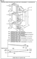
- Fig. 5 shows graphs GR1 and GR2 of a temperature of refrigerant that flows through outdoor heat exchanger 11 during the cooling operation and graphs GA1 and GA2 of a temperature of air that passes through outdoor heat exchanger 11.
- the upper tier shows also outdoor heat exchanger 11 and the like shown in Fig. 3 .
- graph GR1 shows relation between a flow (direction) of air and a temperature of refrigerant that flows through outdoor first heat exchanger 13.
- the temperature of refrigerant immediately before it flows into outdoor first heat exchanger 13 is a temperature TAin and the temperature of refrigerant immediately after it flows through outdoor first heat exchanger 13 is a temperature TAout.
- Graph GR2 shows relation between a flow (direction) of air and a temperature of refrigerant that flows through outdoor second heat exchanger 15.
- the temperature of refrigerant immediately before it flows into outdoor second heat exchanger 15 is a temperature TBin and the temperature of refrigerant immediately after it flows through outdoor second heat exchanger 15 is a temperature TBout.
- Graph GA1 shows relation between a flow (direction) of air and a temperature of air that passes through outdoor first heat exchanger 13.
- Graph GA2 shows relation between a flow (direction) of air and a temperature of air that passes through outdoor second heat exchanger 15.
- refrigerant flows as the counterflow that flows as being opposed to the flow of air (arrow YA).
- refrigerant flows as the parallel flow that flows in parallel to the flow of air (arrow YA).
- the non-azeotropic refrigerant mixture has a property to decrease in temperature as a degree of dryness lowers in a two-phase state.
- refrigerant that flows as the counterflow decreases in temperature as it flows in an orientation opposite to the direction of flow of air.
- refrigerant that flows as the parallel flow decreases in temperature as it flows in a direction the same as the direction of flow of air.
- the temperature of air that passes through outdoor first heat exchanger 13 is higher than the temperature of air that passes through outdoor second heat exchanger 15, and in outdoor heat exchanger 11, an amount of heat exchange between refrigerant and air increases in particular in outdoor first heat exchanger 13. Consequently, performance of air-conditioner 1 during the cooling operation can be improved.
- Fig. 6 shows graphs GR1 and GR2 of a temperature of refrigerant that flows through outdoor heat exchanger 11 during the heating operation and graphs GA1 and GA2 of a temperature of air that passes through outdoor heat exchanger 11.
- the upper tier shows also outdoor heat exchanger 11 and the like shown in Fig. 4 .
- graph GR1 shows relation between a flow (direction) of air and a temperature of refrigerant that flows through outdoor first heat exchanger 13.
- the temperature of refrigerant immediately before it flows into outdoor first heat exchanger 13 is temperature TAin and the temperature of refrigerant immediately after it flows through outdoor first heat exchanger 13 is temperature TAout.
- Graph GR2 shows relation between a flow (direction) of air and a temperature of refrigerant that flows through outdoor second heat exchanger 15.
- the temperature of refrigerant immediately before it flows into outdoor second heat exchanger 15 is temperature TBin and the temperature of refrigerant immediately after it flows through outdoor second heat exchanger 15 is temperature TBout.
- Graph GA1 shows relation between a flow (direction) of air and a temperature of air that passes through outdoor first heat exchanger 13.
- Graph GA2 shows relation between a flow (direction) of air and a temperature of air that passes through outdoor second heat exchanger 15.
- refrigerant flows as the parallel flow that flows in parallel to the flow of air (arrow YA).
- refrigerant flows as the counterflow that flows as being opposed to the flow of air (arrow YA).
- the temperature of air that passes through outdoor second heat exchanger 15 is lower than the temperature of air that passes through outdoor first heat exchanger 13, and in outdoor heat exchanger 11, an amount of heat exchange between refrigerant and air increases in particular in outdoor second heat exchanger 15. Consequently, performance of air-conditioner 1 during the heating operation can be improved.
- outdoor first heat exchanger 13 and outdoor second heat exchanger 15 are connected in parallel with respect to refrigeration cycle circuit 51.
- indoor first heat exchanger 13 and outdoor second heat exchanger 15 are connected in parallel with respect to refrigeration cycle circuit 51.
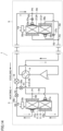
- a Y-shaped or T-shaped branch portion 61 may be provided at each of branch and merge point P1 and branch and merge point P2.
- Y-shaped or T-shaped branch portion 61 may be provided at each of branch and merge point P3 and branch and merge point P4.
- outdoor heat exchanger 11 is provided with an outdoor third heat exchanger 17 as a third heat exchanger in addition to outdoor first heat exchanger 13 and outdoor second heat exchanger 15.
- Outdoor third heat exchanger 17 is connected in series between expansion valve 19 and outdoor first heat exchanger 13 and outdoor second heat exchanger 15 connected in parallel, with respect to refrigeration cycle circuit 51.
- Outdoor first heat exchanger 13 is arranged below outdoor first heat exchanger 13 and outdoor second heat exchanger 15.
- the number of refrigerant flow paths in outdoor first heat exchanger 13 is the first number of refrigerant flow paths
- the number of refrigerant flow paths in outdoor second heat exchanger 15 is the second number of refrigerant flow paths
- the number of refrigerant flow paths in outdoor third heat exchanger 17 is the third number of refrigerant flow paths.
- the third number of refrigerant flow paths is smaller than the first number of refrigerant flow paths and the second number of refrigerant flow paths.
- Outdoor third heat exchanger 17 includes a fifth part 17a and a sixth part 17b.
- Fifth part 17a and sixth part 17b are connected in series.
- Fifth part 17a and sixth part 17b are arranged along the direction of passage of air (see arrow YA).
- Fifth part 17a is arranged on the windward side.
- Sixth part 17b is arranged on the leeward side.
- a gas-liquid two-phase distributor 21c as a third gas-liquid two-phase distributor is connected on a side opposite to a side where sixth part 17b is connected, with respect to fifth part 17a.
- a gas distributor 23c as a third gas distributor is connected on a side opposite to a side where fifth part 17a is connected, with respect to sixth part 17b.
- Air-conditioner 1 is provided with a flow path R5 as a third flow path including a portion through which gas distributor 23c sixth part 17b, fifth part 17a, and gas-liquid two-phase distributor 21c are sequentially connected. Since the construction is otherwise similar to the construction of air-conditioner 1 shown in Figs. 1 and 2 , identical members have identical reference characters allotted and description thereof will not be repeated unless necessary.
- refrigerant flows in parallel through flow path R1 and flow path R2, flows of refrigerant thereafter merge at branch and merge point P2, and merged refrigerant flows through flow path R5.
- flow path R5 refrigerant successively flows through gas distributor 23c, sixth part 17b, fifth part 17a, and gas-liquid two-phase distributor 21c.
- outdoor third heat exchanger 17 refrigerant flows through sixth part 17b arranged on the leeward side and thereafter flows as the counterflow that flows through fifth part 17a arranged on the windward side.
- Refrigerant high-pressure liquid refrigerant
- Refrigerant that flows through outdoor unit 3 passes through expansion valve 19 to become refrigerant in the gas-liquid two-phase state containing low-pressure gas refrigerant and liquid refrigerant.
- Low-pressure refrigerant in the gas-liquid two-phase state flows into indoor unit 5 and becomes low-pressure gas refrigerant, and resultant low-pressure gas refrigerant flows into compressor 7. This cycle is repeated hereafter.
- Refrigerant in the gas-liquid two-phase state flows through the outdoor third heat exchanger (flow path R1) and thereafter flows through outdoor first heat exchanger 13 (flow path R1) and outdoor second heat exchanger 15 (flow path R2) in parallel.
- flow path R5 refrigerant successively flows through gas-liquid two-phase distributor 21c, fifth part 17a, sixth part 17b, and gas distributor 23c.
- outdoor third heat exchanger 17 refrigerant flows through fifth part 17a arranged on the windward side and thereafter flows as the parallel flow that flows through sixth part 17b arranged on the leeward side.
- Air-conditioner 1 described above obtains an effect of suppression of pressure loss of refrigerant and an effect of suppression of increase in amount of refrigerant, as described in connection with air-conditioner 1 according to the first embodiment.
- Air-conditioner 1 according to the second embodiment further obtains an effect as follows.
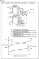
- Fig. 12 shows graphs GR1, GR2, and GR3 of a temperature of refrigerant that flows through outdoor heat exchanger 11 in the cooling operation and graphs GA1, GA2, and GA3 of a temperature of air that passes through outdoor heat exchanger 11.
- the upper tier shows also outdoor heat exchanger 11 and the like shown in Fig. 10 .
- graph GR1 shows relation between a flow (direction) of air and a temperature of refrigerant that flows through outdoor first heat exchanger 13.
- the temperature of refrigerant immediately before it flows into outdoor first heat exchanger 13 is temperature TAin and the temperature of refrigerant immediately after it flows through outdoor first heat exchanger 13 is temperature TAout.
- Graph GR2 shows relation between a flow (direction) of air and a temperature of refrigerant that flows through outdoor second heat exchanger 15.
- the temperature of refrigerant immediately before it flows into outdoor second heat exchanger 15 is temperature TBin and the temperature of refrigerant immediately after it flows through outdoor second heat exchanger 15 is temperature TBout.
- Graph GR3 shows relation between a flow (direction) of air and a temperature of refrigerant that flows through outdoor third heat exchanger 17.
- the temperature of refrigerant immediately before it flows into outdoor third heat exchanger 17 is a temperature TCin and the temperature of refrigerant immediately after it flows through outdoor third heat exchanger 17 is a temperature TCout.
- Graph GA1 shows relation between a flow (direction) of air and a temperature of air that passes through outdoor first heat exchanger 13.
- Graph GA2 shows relation between a flow (direction) of air and a temperature of air that passes through outdoor second heat exchanger 15.
- Graph GA3 shows relation between a flow (direction) of air and a temperature of air that passes through outdoor third heat exchanger 17.
- refrigerant flows as the counterflow that flows as being opposed to the flow of air (arrow YA).
- refrigerant flows as the parallel flow that flows in parallel to the flow of air (arrow YA).
- refrigerant flows as the counterflow that flows as being opposed to the flow of air (arrow YA).
- Refrigerant that flows through outdoor second heat exchanger 15 as the parallel flow flows into outdoor third heat exchanger 17, together with refrigerant that flows through outdoor first heat exchanger 13.
- refrigerant flows as the counterflow.
- the temperature difference between refrigerant and air can thus be ensured, and the amount of heat exchange between refrigerant and air in outdoor third heat exchanger 17 can be increased. Consequently, performance during the cooling operation can further be improved.
- Fig. 13 shows graphs GR1, GR2, and GR3 of a temperature of refrigerant that flows through outdoor heat exchanger 11 during the heating operation and graphs GA1, GA2, and GA3 of a temperature of air that passes through outdoor heat exchanger 11.
- the upper tier shows also outdoor heat exchanger 11 and the like shown in Fig. 11 .
- graph GR1 shows relation between a flow (direction) of air and a temperature of refrigerant that flows through outdoor first heat exchanger 13.
- the temperature of refrigerant immediately before it flows into outdoor first heat exchanger 13 is temperature TAin and the temperature of refrigerant immediately after it flows through outdoor first heat exchanger 13 is temperature TAout.
- Graph GR2 shows relation between a flow (direction) of air and a temperature of refrigerant that flows through outdoor second heat exchanger 15.
- the temperature of refrigerant immediately before it flows into outdoor second heat exchanger 15 is temperature TBin and the temperature of refrigerant immediately after it flows through outdoor second heat exchanger 15 is temperature TBout.
- Graph GR3 shows relation between a flow (direction) of air and a temperature of refrigerant that flows through outdoor third heat exchanger 17.
- the temperature of refrigerant immediately before it flows into outdoor third heat exchanger 17 is temperature TCin and the temperature of refrigerant immediately after it flows through outdoor third heat exchanger 17 is temperature TCout.
- Graph GA1 shows relation between a flow (direction) of air and a temperature of air that passes through outdoor first heat exchanger 13.
- Graph GA2 shows relation between a flow (direction) of air and a temperature of air that passes through outdoor second heat exchanger 15.
- Graph GA3 shows relation between a flow (direction) of air and a temperature of air that passes through outdoor third heat exchanger 17.
- Refrigerant that is sent to outdoor unit 3 and passes through expansion valve 19 to be in the gas-liquid two-phase state flows through outdoor third heat exchanger 17, and thereafter flows in parallel through outdoor first heat exchanger 13 and outdoor second heat exchanger 15.
- refrigerant in the gas-liquid two-phase state flows as the parallel flow.
- the third number of refrigerant flow paths in outdoor third heat exchanger 17 is smaller than the first number of refrigerant flow paths in outdoor first heat exchanger 13 and the second number of refrigerant flow paths in outdoor second heat exchanger 15. Therefore, outdoor third heat exchanger 17 is relatively higher in pressure loss of refrigerant than outdoor first heat exchanger 13 and outdoor second heat exchanger 15.
- the temperature of refrigerant (see graph GR3) that flows through outdoor third heat exchanger 17 is thus higher than the temperature of refrigerant (see graph GR1) that flows through outdoor first heat exchanger 13 and the temperature of refrigerant (see graph GR2) that flows through outdoor second heat exchanger 15.
- Outdoor third heat exchanger 17 is arranged below outdoor first heat exchanger 13 and outdoor second heat exchanger 15. In the heating operation, condensation water attached to outdoor first heat exchanger 13 and outdoor second heat exchanger 15 flows down to outdoor third heat exchanger 17 arranged below and frost tends to grow in outdoor third heat exchanger 17.
- an outdoor first flow rate regulation valve 25a and an outdoor second flow rate regulation valve 25b are arranged in outdoor unit 3.
- Outdoor first flow rate regulation valve 25a is arranged in flow path R1. Outdoor first flow rate regulation valve 25a is arranged in a portion of flow path R1 between branch and merge point P2 and gas-liquid two-phase distributor 21a. Outdoor second flow rate regulation valve 25b is arranged in flow path R2. Outdoor second flow rate regulation valve 25b is arranged in a portion of flow path R2 between branch and merge point P2 and gas-liquid two-phase distributor 21b.
- An indoor first flow rate regulation valve 37a and an indoor second flow rate regulation valve 37b are arranged in indoor unit 5.
- Indoor first flow rate regulation valve 37a is arranged in flow path R3.
- Indoor first flow rate regulation valve 37a is arranged in a portion of flow path R3 between branch and merge point P4 and gas-liquid two-phase distributor 33a.
- Indoor second flow rate regulation valve 37b is arranged in a portion of flow path R4 between branch and merge point P4 and gas-liquid two-phase distributor 33b.
- a solenoid valve or an electronic expansion valve can be employed as outdoor first flow rate regulation valve 25a, outdoor second flow rate regulation valve 25b, indoor first flow rate regulation valve 37a, and indoor second flow rate regulation valve 37b.
- expansion valve 19 does not have to be provided. Since the construction is otherwise similar to the construction of air-conditioner 1 shown in Figs. 1 and 2 , identical members have identical reference characters allotted and description thereof will not be repeated unless necessary.
- refrigerant In flow path R1, refrigerant successively flows through gas distributor 23a, second part 13b, first part 13a, gas-liquid two-phase distributor 21a, and outdoor first flow rate regulation valve 25a.
- outdoor first heat exchanger 13 refrigerant flows through second part 13b arranged on the leeward side and thereafter flows as the counterflow that flows through first part 13a arranged on the windward side.
- refrigerant In flow path R2, refrigerant successively flows through gas distributor 23b, third part 15a, fourth part 15b, gas-liquid two-phase distributor 21b, and outdoor second flow rate regulation valve 25b.
- refrigerant flows through third part 15a arranged on the windward side and thereafter flows as the parallel flow that flows through fourth part 15b arranged on the leeward side.
- Refrigerant that flows through flow path R1 and refrigerant that flows through flow path R2 merge, and merged refrigerant passes through expansion valve 19 to become refrigerant in the gas-liquid two-phase state containing low-pressure gas refrigerant and liquid refrigerant.
- Resultant low-pressure refrigerant in the gas-liquid two-phase state is sent to indoor unit 5.
- Refrigerant sent to indoor unit 5 flows through flow path R3 (indoor first heat exchanger 29) and flow path R4 (indoor second heat exchanger 31) in parallel.
- refrigerant successively flows through indoor first flow rate regulation valve 37a, gas-liquid two-phase distributor 33a, indoor first heat exchanger 29, and gas distributor 35a.
- indoor first heat exchanger 29 refrigerant flows as the parallel flow.
- refrigerant successively flows through indoor second flow rate regulation valve 37b, gas-liquid two-phase distributor 33b, indoor second heat exchanger 31, and gas distributor 35b.
- indoor second heat exchanger 31 refrigerant flows as the counterflow.
- Refrigerant that flows through flow path R3 and refrigerant that flows through flow path R4 merge, and merged refrigerant flows into compressor 7. This cycle is repeated hereafter.
- refrigerant successively flows through gas distributor 35a, indoor first heat exchanger 29, gas-liquid two-phase distributor 33a, and indoor first flow rate regulation valve 37a.
- indoor first heat exchanger 29 refrigerant flows as the counterflow.
- flow path R4 refrigerant successively flows through gas distributor 35b, indoor second heat exchanger 31, gas-liquid two-phase distributor 33b, and indoor second flow rate regulation valve 37b.
- refrigerant flows as the parallel flow.
- Refrigerant that flows through flow path R3 and refrigerant that flows through flow path R4 merge, and merged refrigerant is sent to outdoor unit 3 and passes through expansion valve 19 to become refrigerant in the gas-liquid two-phase state containing low-pressure gas refrigerant and liquid refrigerant.
- Refrigerant in the gas-liquid two-phase state flows through flow path R1 (outdoor first heat exchanger 13) and flow path R2 (outdoor second heat exchanger 15) in parallel.
- refrigerant in flow path R1, refrigerant successively flows through outdoor first flow rate regulation valve 25a, gas-liquid two-phase distributor 21a, first part 13a, second part 13b, and gas distributor 23a. In outdoor first heat exchanger 13, refrigerant flows as the parallel flow. In flow path R2, refrigerant successively flows through outdoor second flow rate regulation valve 25b, gas-liquid two-phase distributor 21b, fourth part 15b, third part 15a, and gas distributor 23b. In outdoor second heat exchanger 15, refrigerant flows as the counterflow.
- Refrigerant that flows through flow path R1 and refrigerant that flows through flow path R2 merge, and merged refrigerant flows into compressor 7 through four-way valve 9. This cycle is repeated hereafter.
- Air-conditioner 1 described above obtains an effect of suppression of pressure loss of refrigerant and an effect of suppression of increase in amount of refrigerant, as described in connection with air-conditioner 1 according to the first embodiment.
- Air-conditioner 1 according to the third embodiment further obtains an effect as follows.
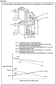
- Fig. 18 shows graphs GR1 and GR2 of a temperature of refrigerant that flows through outdoor heat exchanger 11 during the cooling operation and graphs GA1 and GA2 of a temperature of air that passes through outdoor heat exchanger 11.
- the upper tier shows also outdoor heat exchanger 11 and the like shown in Fig. 16 .
- graph GR1 shows relation between a flow (direction) of air and a temperature of refrigerant that flows through outdoor first heat exchanger 13.
- the temperature of refrigerant immediately before it flows into outdoor first heat exchanger 13 is temperature TAin and the temperature of refrigerant immediately after it flows through outdoor first heat exchanger 13 is temperature TAout.
- Graph GR2 shows relation between a flow (direction) of air and a temperature of refrigerant that flows through outdoor second heat exchanger 15.
- the temperature of refrigerant immediately before it flows into outdoor second heat exchanger 15 is temperature TBin and the temperature of refrigerant immediately after it flows through outdoor second heat exchanger 15 is temperature TBout.
- Graph GA1 shows relation between a flow (direction) of air and a temperature of air that passes through outdoor first heat exchanger 13.
- Graph GA2 shows relation between a flow (direction) of air and a temperature of air that passes through outdoor second heat exchanger 15.
- temperature TBout of refrigerant immediately after it flows through outdoor second heat exchanger 15 is lower than in an example where outdoor first flow rate regulation valve 25a and outdoor second flow rate regulation valve 25b are not provided (see Fig. 5 ). Temperature TAout of refrigerant immediately after it flows through outdoor first heat exchanger 13 is higher than in the example where outdoor first flow rate regulation valve 25a and outdoor second flow rate regulation valve 25b are not provided (see Fig. 5 ).
- outdoor second flow rate regulation valve 25b and the like can decrease a difference between temperature TAout and temperature TBout. Therefore, by regulating the flow rate of refrigerant with the use of outdoor second flow rate regulation valve 25b and the like such that temperature TAout (outlet side enthalpy) of refrigerant immediately after it flows through outdoor first heat exchanger 13 is substantially the same as temperature TBout (outlet side enthalpy) of refrigerant immediately after it flows through outdoor second heat exchanger 15, heat transfer performance of outdoor heat exchanger 11 can be improved.
- Fig. 19 shows graphs GR1 and GR2 of a temperature of refrigerant that flows through outdoor heat exchanger 11 during the heating operation and graphs GA1 and GA2 of a temperature of air that passes through outdoor heat exchanger 11.
- the upper tier shows also outdoor heat exchanger 11 and the like shown in Fig. 17 .
- graph GR1 shows relation between a flow (direction) of air and a temperature of refrigerant that flows through outdoor first heat exchanger 13.
- the temperature of refrigerant immediately before it flows into outdoor first heat exchanger 13 is temperature TAin and the temperature of refrigerant immediately after it flows through outdoor first heat exchanger 13 is temperature TAout.
- Graph GR2 shows relation between a flow (direction) of air and a temperature of refrigerant that flows through outdoor second heat exchanger 15.
- the temperature of refrigerant immediately before it flows into outdoor second heat exchanger 15 is temperature TBin and the temperature of refrigerant immediately after it flows through outdoor second heat exchanger 15 is temperature TBout.
- Graph GA1 shows relation between a flow (direction) of air and a temperature of air that passes through outdoor first heat exchanger 13.
- Graph GA2 shows relation between a flow (direction) of air and a temperature of air that passes through outdoor second heat exchanger 15.
- temperature TAout of refrigerant immediately after it flows through outdoor first heat exchanger 13 is higher than in the example where outdoor first flow rate regulation valve 25a and outdoor second flow rate regulation valve 25b are not provided (see Fig. 5 ).
- Temperature TBout of refrigerant immediately after it flows through outdoor second heat exchanger 15 is lower than in the example where outdoor first flow rate regulation valve 25a and outdoor second flow rate regulation valve 25b are not provided (see Fig. 5 ).
- outdoor first flow rate regulation valve 25a and the like can decrease difference between temperature TAout and temperature TBout. Therefore, by regulating the flow rate of refrigerant with the use of outdoor first flow rate regulation valve 25a and the like such that temperature TAout (outlet side enthalpy) of refrigerant immediately after it flows through outdoor first heat exchanger 13 is substantially the same as temperature TBout (outlet side enthalpy) of refrigerant immediately after it flows through outdoor second heat exchanger 15, heat transfer performance of outdoor heat exchanger 11 can be improved.
- a temperature sensor such as a thermistor may be provided in refrigerant pipe 41.
- a temperature sensor T1 is provided in a portion S1 of refrigerant pipe 41 located opposite to the side where first part 13a is connected, with respect to gas-liquid two-phase distributor 21a, and a temperature sensor T2 is arranged in a portion S2 of refrigerant pipe 41 located opposite to the side where second part 13b is connected, with respect to gas distributor 23a.
- a temperature sensor T4 is provided in a portion S4 of refrigerant pipe 41 located opposite to the side where fourth part 15b is connected, with respect to gas-liquid two-phase distributor 21b, and a temperature sensor T3 is provided in a portion S3 of refrigerant pipe 41 located opposite to the side where third part 15a is connected, with respect to gas distributor 23b.
- a pressure sensor may be provided in refrigerant pipe 41 (portions S1 to S4) other than temperature sensors T1 to T4.
- Each outlet side enthalpy can more accurately be calculated with the use of the pressure sensor.
- a two-row structure including two rows of heat transfer tubes where first part 13a (third part 15a) and second part 13b (fourth part 15b) are arranged in the direction of passage of air is exemplified as outdoor heat exchanger 11 or the like
- a multiple-row structure including three or more rows may be applicable.
- a circular tube having a circular cross-section or a low-profile tube having a low-profile cross-section may be applicable as the heat transfer tube arranged in outdoor heat exchanger 11 or the like.
- indoor heat exchanger 27 in indoor unit 5 also obtains an effect similar to that of outdoor heat exchanger 11. Furthermore, at least one of outdoor heat exchanger 11 and indoor heat exchanger 27 should only be applied as the first heat exchanger and the second heat exchanger.
- Air-conditioner 1 described in each embodiment can variously be combined as necessary.
- the present disclosure is effectively made use of as an air-conditioner where a non-azeotropic refrigerant mixture is used as refrigerant.
Landscapes
- Engineering & Computer Science (AREA)
- Mechanical Engineering (AREA)
- General Engineering & Computer Science (AREA)
- Physics & Mathematics (AREA)
- Thermal Sciences (AREA)
- Chemical & Material Sciences (AREA)
- Combustion & Propulsion (AREA)
- Compression-Type Refrigeration Machines With Reversible Cycles (AREA)
Abstract
Description
- The present disclosure relates to an air-conditioner.
- A non-azeotropic refrigerant mixture obtained by mixing at least two types of refrigerant is available as refrigerant to be used in a refrigeration cycle apparatus such as an air-conditioner.
PTL 1 andPTL 2 disclose a refrigeration cycle apparatus where such a non-azeotropic refrigerant mixture is used. - In a heat exchanger in the refrigeration cycle apparatus where the non-azeotropic refrigerant mixture is used, in order to enhance efficiency of heat exchange between refrigerant and air, the heat exchanger is required to allow refrigerant to flow as a counterflow reverse in orientation to a direction of passage of air through the heat exchanger.
- Therefore, various proposals have been made such that refrigerant flows through the heat exchanger as the counterflow in both of a case where the heat exchanger functions as a condenser and a case where the heat exchanger functions as an evaporator.
Japanese Patent Laying-Open No. H08-170864 Japanese Patent Laying-Open No. H09-196489 -
- PTL 1:
Japanese Patent Laying-Open No. H08-170864 - PTL 2:
Japanese Patent Laying-Open No. H09-196489 - In general, when a heat exchanger functions as an evaporator, in order to distribute refrigerant in a gas-liquid two-phase state containing gas refrigerant and liquid refrigerant that flows into the heat exchanger, a gas-liquid two-phase distributor is arranged on a refrigerant inlet side of the heat exchanger. In the gas-liquid two-phase distributor, in order to uniformly distribute refrigerant in the gas-liquid two-phase state, for example, an orifice is arranged.
- When a heat exchanger functions as a condenser, on the other hand, in order to suppress pressure loss of gas refrigerant that flows into the heat exchanger, a gas distributor relatively large in volume is arranged on the refrigerant inlet side of the heat exchanger.
- In a heat exchanger where general refrigerant is used, an orientation of a flow of refrigerant when the heat exchanger functions as the condenser is reverse to an orientation of a flow of refrigerant when the heat exchanger functions as the evaporator. Therefore, the gas-liquid two-phase distributor is arranged on one side of the heat exchanger and a gas distributor is arranged on the other side thereof.
- In contrast, in the heat exchanger where the non-azeotropic refrigerant mixture is used, an orientation of a flow of refrigerant when the heat exchanger functions as the condenser is the same as an orientation of a flow of refrigerant when the heat exchanger functions as the evaporator.
- Therefore, in an example where the heat exchanger functions as the condenser, for example, when gas refrigerant flows through the gas-liquid two-phase distributor where a distributor is arranged, the pressure loss is great. In an example where the heat exchanger functions as the evaporator, for example, when gas refrigerant that has exchanged heat flows through the gas-liquid two-phase distributor where a distributor is arranged, the pressure loss is great.
- The present disclosure was made to solve such a technical problem, and an object thereof is to provide an air-conditioner where a non-azeotropic refrigerant mixture is used, the air-conditioner capable of achieving reduction in pressure loss.
- An air-conditioner according to the present disclosure includes a refrigeration cycle circuit provided with an outdoor unit and an indoor unit, a non-azeotropic refrigerant mixture circulating through the refrigeration cycle circuit. At least one of the outdoor unit and the indoor unit includes a first heat exchanger, a second heat exchanger, a first gas-liquid two-phase distributor, a first gas distributor, a second gas distributor, a second gas-liquid two-phase distributor, a first flow path, and a second flow path. The first heat exchanger includes a first part and a second part connected in series. The second heat exchanger includes a third part and a fourth part connected in series. The first gas-liquid two-phase distributor is connected on a side opposite to a side where the second part is connected, with respect to the first part. The first gas distributor is connected on a side opposite to a side where the first part is connected, with respect to the second part. The second gas distributor is connected on a side opposite to a side where the fourth part is connected, with respect to the third part. The second gas-liquid two-phase distributor is connected on a side opposite to a side where the third part is connected, with respect to the fourth part. The first flow path includes a portion through which the first gas distributor, the second part, the first part, and the first gas-liquid two-phase distributor are sequentially connected. The second flow path includes a portion through which the second gas distributor, the third part, the fourth part, and the second gas-liquid two-phase distributor are sequentially connected. The first flow path where the first heat exchanger is arranged and the second flow path where the second heat exchanger is arranged are connected in parallel with respect to the refrigeration cycle circuit in such a manner that the first gas-liquid two-phase distributor and the second gas-liquid two-phase distributor are connected and the first gas distributor and the second gas distributor are connected. The air-conditioner has a first operation mode in which the first heat exchanger and the second heat exchanger function as a condenser and a second operation mode in which the first heat exchanger and the second heat exchanger function as an evaporator. With respect to a direction of passage of air that passes through the first heat exchanger and the second heat exchanger, the first part is arranged on a windward side, the second part is arranged on a leeward side, the third part is arranged on the windward side, and the fourth part is arranged on the leeward side.
- According to the air-conditioner according to the present disclosure, in the first operation mode, in the first flow path, a gaseous non-azeotropic refrigerant mixture flows into the first gas distributor and becomes liquid refrigerant in the first heat exchanger, and resultant liquid refrigerant flows through the first gas-liquid two-phase distributor, and in the second flow path, the gaseous non-azeotropic refrigerant mixture flows into the second gas distributor and becomes liquid refrigerant in the second heat exchanger, and resultant liquid refrigerant flows through the second gas-liquid two-phase distributor. In the second operation mode, in the first flow path, the non-azeotropic refrigerant mixture in the gas-liquid two-phase state flows into the first gas-liquid two-phase distributor and becomes gaseous refrigerant in the first heat exchanger, and resultant gaseous refrigerant flows through the first gas distributor, and in the second flow path, the non-azeotropic refrigerant mixture in the gas-liquid two-phase state flows into the second gas-liquid two-phase distributor and becomes gaseous refrigerant in the second heat exchanger, and resultant gaseous refrigerant flows through the first gas distributor. The pressure loss of the non-azeotropic refrigerant mixture that circulates through the refrigeration cycle circuit can thus be reduced.
-
-
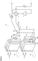
Fig. 1 is a diagram showing a refrigeration cycle circuit of an air-conditioner according to a first embodiment. -
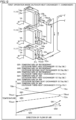
Fig. 2 is a perspective view schematically showing a structure of an outdoor heat exchanger and the like in an outdoor unit in the embodiment. -
Fig. 3 is a perspective view for illustrating a flow of refrigerant in the outdoor heat exchanger and the like during a cooling operation in the embodiment. -
Fig. 4 is a perspective view for illustrating a flow of refrigerant in the outdoor heat exchanger and the like during a heating operation in the embodiment. -
Fig. 5 is a diagram including a graph of a temperature of refrigerant and a graph of a temperature of air for illustrating a function and effect of the outdoor heat exchanger and the like during the cooling operation in the embodiment. -
Fig. 6 is a diagram including a graph of a temperature of refrigerant and a graph of a temperature of air for illustrating a function and effect of the outdoor heat exchanger and the like during the heating operation in the embodiment. -
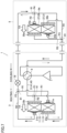
Fig. 7 is a diagram showing the refrigeration cycle circuit of the air-conditioner according to a modification in the embodiment. -
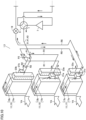
Fig. 8 is a diagram showing the refrigeration cycle circuit of the air-conditioner according to a second embodiment. -
Fig. 9 is a perspective view schematically showing a structure of the outdoor heat exchanger and the like in the outdoor unit in the embodiment. -
Fig. 10 is a perspective view for illustrating a flow of refrigerant in the outdoor heat exchanger and the like during the cooling operation in the embodiment. -
Fig. 11 is a perspective view for illustrating a flow of refrigerant in the outdoor heat exchanger and the like during the heating operation in the embodiment. -
Fig. 12 is a diagram including a graph of a temperature of refrigerant and a graph of a temperature of air for illustrating a function and effect of the outdoor heat exchanger and the like during the cooling operation in the embodiment. -
Fig. 13 is a diagram including a graph of a temperature of refrigerant and a graph of a temperature of air for illustrating a function and effect of the outdoor heat exchanger and the like during the heating operation in the embodiment. -
Fig. 14 is a diagram showing the refrigeration cycle circuit of the air-conditioner according to a third embodiment. -
Fig. 15 is a perspective view schematically showing a structure of the outdoor heat exchanger and the like in the outdoor unit in the embodiment. -
Fig. 16 is a perspective view for illustrating a flow of refrigerant in the outdoor heat exchanger and the like during the cooling operation in the embodiment. -
Fig. 17 is a perspective view for illustrating a flow of refrigerant in the outdoor heat exchanger and the like during the heating operation in the embodiment. -
Fig. 18 is a diagram including a graph of a temperature of refrigerant and a graph of a temperature of air for illustrating a function and effect of the outdoor heat exchanger and the like during the cooling operation in the embodiment. -
Fig. 19 is a diagram including a graph of a temperature of refrigerant and a graph of a temperature of air for illustrating a function and effect of the outdoor heat exchanger and the like during the heating operation in the embodiment. - An exemplary air-conditioner according to a first embodiment will be described. As shown in
Fig. 1 , an air-conditioner 1 is provided with anoutdoor unit 3 and anindoor unit 5. Acompressor 7, a four-way valve 9, anoutdoor heat exchanger 11, anexpansion valve 19, and the like are accommodated inoutdoor unit 3. An indoor heat exchanger 27 and the like are accommodated inindoor unit 5. -
Compressor 7, four-way valve 9,outdoor heat exchanger 11,expansion valve 19, and indoor heat exchanger 27 are connected through a refrigerant pipe 41 to make up a refrigeration cycle circuit 51. Refrigerant circulates through refrigeration cycle circuit 51 (refrigerant pipe 41). In air-conditioner 1, a non-azeotropic refrigerant mixture 43 is used as refrigerant. Non-azeotropic refrigerant mixture 43 refers to a refrigerant mixture obtained by mixing a plurality of single components, in which a gas phase and a liquid phase thereof are different in component from each other. -
Outdoor heat exchanger 11 and the like will be described in detail. As shown inFigs. 1 and2 ,outdoor heat exchanger 11 includes an outdoor first heat exchanger 13 as a first heat exchanger and an outdoorsecond heat exchanger 15 as a second heat exchanger. Outdoorsecond heat exchanger 15 is arranged on outdoor first heat exchanger 13. Outdoor first heat exchanger 13 includes afirst part 13a and asecond part 13b.First part 13a andsecond part 13b are connected in series.First part 13a andsecond part 13b are arranged along a direction of passage of air (see an arrow YA).First part 13a is arranged on a windward side.Second part 13b is arranged on a leeward side. - A gas-liquid two-
phase distributor 21a as a first gas-liquid two-phase distributor is connected on a side opposite to a side wheresecond part 13b is connected, with respect tofirst part 13a. Agas distributor 23a as a first gas distributor is connected on a side opposite to a side wherefirst part 13a is connected, with respect tosecond part 13b. - Outdoor
second heat exchanger 15 includes athird part 15a and afourth part 15b.Third part 15a andfourth part 15b are connected in series.Third part 15a andfourth part 15b are arranged along the direction of passage of air (see arrow YA).Third part 15a is arranged on the windward side.Fourth part 15b is arranged on the leeward side. - A gas-liquid two-
phase distributor 21b as a second gas-liquid two-phase distributor is connected on a side opposite to a side wherethird part 15a is connected, with respect tofourth part 15b. Agas distributor 23b as a second gas distributor is connected on a side opposite to a side wherefourth part 15b is connected, with respect tothird part 15a. - Air-
conditioner 1 is provided with a flow path R1 as a first flow path including a portion through whichgas distributor 23a,second part 13b,first part 13a, and gas-liquid two-phase distributor 21a are sequentially connected. A flow path R2 as a second flow path including a portion through whichgas distributor 23b,third part 15a,fourth part 15b, and gas-liquid two-phase distributor 21b are sequentially connected is provided. - Flow path R1 where outdoor first heat exchanger 13 is arranged and flow path R2 where outdoor
second heat exchanger 15 is arranged are connected in parallel with respect to refrigeration cycle circuit 51 in such a manner that gas-liquid two-phase distributor 21a and gas-liquid two-phase distributor 21b are connected andgas distributor 23a andgas distributor 23b are connected. In other words, flow path R1 and flow path R2 are connected in parallel with respect to refrigeration cycle circuit 51 (main flow path) through which the non-azeotropic refrigerant mixture circulates. - Indoor heat exchanger 27 and the like will now be described. As shown in
Fig. 1 , indoor heat exchanger 27 includes an indoor first heat exchanger 29 and an indoor second heat exchanger 31. - A gas-liquid two-
phase distributor 33a is connected on one end side of indoor first heat exchanger 29. Agas distributor 35a is connected on the other end side of indoor first heat exchanger 29. A gas-liquid two-phase distributor 33b is connected on one end side of indoor second heat exchanger 31. Agas distributor 35b is connected on the other end side of indoor second heat exchanger 31. - Air-
conditioner 1 is provided with a flow path R3 including a portion through whichgas distributor 35a, gas-liquid two-phase distributor 33a, and indoor first heat exchanger 29 are sequentially connected. A flow path R4 including a portion through whichgas distributor 35b, indoor second heat exchanger 31, and gas-liquid two-phase distributor 33b are sequentially connected is provided. - Flow path R3 where indoor first heat exchanger 29 is arranged and indoor second heat exchanger 31 where indoor second heat exchanger 31 is arranged are connected in parallel with respect to refrigeration cycle circuit 51 in such a manner that gas-liquid two-
phase distributor 33a and gas-liquid two-phase distributor 33b are connected andgas distributor 35a andgas distributor 35b are connected. In other words, flow path R3 and flow path R4 are connected in parallel with respect to refrigeration cycle circuit 51 (main flow path) through which a non-azeotropic refrigerant mixture circulates. Air-conditioner 1 according to the first embodiment is composed as above. - An operation (a flow of refrigerant) of air-conditioner 1 (refrigeration cycle circuit 51) described above will now be described.
- A cooling operation as a first operation mode will initially be described as an operation of air-conditioner 1 (refrigeration cycle circuit 51). In this case,
outdoor heat exchanger 11 inoutdoor unit 3 functions as a condenser and indoor heat exchanger 27 inindoor unit 5 functions as an evaporator. - As
compressor 7 is driven, high-temperature and high-pressure gas refrigerant (single phase) is discharged fromcompressor 7. Discharged high-temperature and high-pressure gas refrigerant is sent through four-way valve 9 tooutdoor unit 3. Inoutdoor unit 3, sent refrigerant flows throughoutdoor heat exchanger 11. At this time, refrigerant flows through outdoor first heat exchanger 13 (flow path R1) and outdoor second heat exchanger 15 (flow path R2) in parallel. The flow of refrigerant inoutdoor heat exchanger 11 will be described in detail later. - In
outdoor heat exchanger 11, heat is exchanged between refrigerant that flows in and air supplied by a propeller fan (not shown). High-temperature and high-pressure gas refrigerant becomes high-pressure liquid refrigerant (single phase) by being condensed as a result of heat exchange. - High-pressure liquid refrigerant that flows through
outdoor heat exchanger 11 and is sent out ofoutdoor unit 3 is converted byexpansion valve 19 into refrigerant in the gas-liquid two-phase state containing low-pressure gas refrigerant and liquid refrigerant. Refrigerant in the gas-liquid two-phase state is sent toindoor unit 5. Inindoor unit 5, sent refrigerant flows through indoor heat exchanger 27. At this time, refrigerant flows through indoor first heat exchanger 29 (flow path R3) and indoor second heat exchanger 31 (flow path R4) in parallel. - In indoor heat exchanger 27, heat is exchanged between refrigerant in the gas-liquid two-phase state that flows in and air sent into indoor heat exchanger 27 by a fan (not shown). Refrigerant in the gas-liquid two-phase state becomes low-pressure gas refrigerant (single phase) as a result of evaporation of liquid refrigerant by heat exchange. Air that has exchanged heat is sent from indoor heat exchanger 27 into an indoor space so that the indoor space is cooled.
- Low-pressure gas refrigerant that flows through indoor heat exchanger 27 and is sent out of
indoor unit 5 flows through four-way valve 9 intocompressor 7. Low-pressure gas refrigerant that flows intocompressor 7 becomes high-temperature and high-pressure gas refrigerant by being compressed and is discharged again fromcompressor 7. This cycle is repeated hereafter. - A heating operation as a second operation mode will be described as an operation of air-conditioner 1 (refrigeration cycle circuit 51). In this case, indoor heat exchanger 27 in
indoor unit 5 functions as the condenser andoutdoor heat exchanger 11 inoutdoor unit 3 functions as the evaporator. - As
compressor 7 is driven, high-temperature and high-pressure gas refrigerant (single phase) is discharged fromcompressor 7. Discharged high-temperature and high-pressure gas refrigerant (single phase) is sent through four-way valve 9 toindoor unit 5. Refrigerant sent toindoor unit 5 flows through indoor heat exchanger 27. At this time, refrigerant flows through indoor first heat exchanger 29 (flow path R3) and indoor second heat exchanger 31 (flow path R4) in parallel. - In indoor heat exchanger 27, heat is exchanged between gas refrigerant that flows in and air sent by the fan (not shown). High-temperature and high-pressure gas refrigerant becomes high-pressure liquid refrigerant (single phase) by being condensed. Air that has exchanged heat is sent from indoor heat exchanger 27 into the indoor space so that the indoor space is heated. High-pressure liquid refrigerant that flows through indoor heat exchanger 27 and is sent out of
indoor unit 5 is sent to the outdoor unit. - High-pressure liquid refrigerant sent to
outdoor unit 3 is converted byexpansion valve 19 into refrigerant in the gas-liquid two-phase state containing low-pressure gas refrigerant and liquid refrigerant. Refrigerant in the gas-liquid two-phase state flows throughoutdoor heat exchanger 11. At this time, refrigerant flows through outdoor first heat exchanger 13 (flow path R1) and outdoor second heat exchanger 15 (flow path R2) in parallel. - In
outdoor heat exchanger 11, heat is exchanged between refrigerant in the gas-liquid two-phase state that flows in and air supplied by the propeller fan (not shown). Liquid refrigerant in refrigerant in the gas-liquid two-phase state evaporates, and refrigerant in the gas-liquid two-phase state becomes low-pressure gas refrigerant (single phase). - Low-pressure gas refrigerant that flows through
outdoor heat exchanger 11 and is sent out ofoutdoor unit 3 flows through four-way valve 9 intocompressor 7. Low-pressure gas refrigerant that flows intocompressor 7 becomes high-temperature and high-pressure gas refrigerant by being compressed and is again discharged fromcompressor 7. This cycle is repeated hereafter. - Since
outdoor heat exchanger 11 functions as the evaporator in the heating operation, frost may grow inoutdoor heat exchanger 11. Therefore, in air-conditioner 1, a defrosting operation to remove frost that grows inoutdoor heat exchanger 11 is performed. In the defrosting operation, by sending high-temperature and high-pressure refrigerant discharged fromcompressor 7 tooutdoor heat exchanger 11 by performing an operation the same as the cooling operation, frost that grows inoutdoor heat exchanger 11 is removed. - A general flow of refrigerant in air-conditioner 1 (refrigeration cycle circuit 51) is as described above. A flow of refrigerant in
outdoor heat exchanger 11 and indoor heat exchanger 27 will now more specifically be described. - As shown in
Figs. 1 and3 , high-temperature and high-pressure gas refrigerant (single phase) discharged fromcompressor 7 is sent through four-way valve 9 tooutdoor unit 3. Inoutdoor unit 3, refrigerant is branched at a branch and merge point P1 into refrigerant that flows through flow path R1 and refrigerant that flows through flow path R2. - In flow path R1, high-temperature and high-pressure gas refrigerant successively flows through
gas distributor 23a,second part 13b,first part 13a, and gas-liquid two-phase distributor 21a. In flow path R1, high-temperature and high-pressure gas refrigerant flows intogas distributor 23a and is condensed in outdoor first heat exchanger 13 to become high-pressure liquid refrigerant, and resultant high-pressure liquid refrigerant flows through gas-liquid two-phase distributor 21a. In outdoor first heat exchanger 13, refrigerant flows throughsecond part 13b arranged on the leeward side and thereafter flows as a counterflow that flows throughfirst part 13a arranged on the windward side. - In flow path R2, high-temperature and high-pressure gas refrigerant successively flows through
gas distributor 23b,third part 15a,fourth part 15b, and gas-liquid two-phase distributor 21b. In flow path R2, high-temperature and high-pressure gas refrigerant flows intogas distributor 23b and is condensed in outdoorsecond heat exchanger 15 to become high-pressure liquid refrigerant, and resultant high-pressure liquid refrigerant flows through gas-liquid two-phase distributor 21b. In outdoorsecond heat exchanger 15, refrigerant flows throughthird part 15a arranged on the windward side and thereafter flows as a parallel flow that flows throughfourth part 15b arranged on the leeward side. - High-pressure liquid refrigerant that flows through gas-liquid two-
phase distributor 21a and high-pressure liquid refrigerant that flows through gas-liquid two-phase distributor 21b merge at a branch and merge point P2, and after merged refrigerant passes throughexpansion valve 19, it becomes refrigerant in the gas-liquid two-phase state containing low-pressure gas refrigerant and liquid refrigerant. Low-pressure refrigerant in the gas-liquid two-phase state is sent to indoor unit 5 (seeFig. 1 ). - A flow of refrigerant in
indoor unit 5 will now briefly be described in accordance withoutdoor unit 3. As shown inFig. 1 , refrigerant that flows intoindoor unit 5 is branched at a branch and merge point P4 into refrigerant that flows through flow path R3 and refrigerant that flows through flow path R4. - In flow path R3, refrigerant in the gas-liquid two-phase state successively flows through gas-liquid two-
phase distributor 33a, indoor first heat exchanger 29, andgas distributor 35a. In flow path R3, low-pressure refrigerant in the gas-liquid two-phase state flows through gas-liquid two-phase distributor 33a and is evaporated in indoor first heat exchanger 29 to become low-pressure gas refrigerant, and resultant low-pressure gas refrigerant flows throughgas distributor 35a. In indoor first heat exchanger 29, refrigerant flows as the parallel flow. - In flow path R4, refrigerant in the gas-liquid two-phase state successively flows through gas-liquid two-
phase distributor 33b, indoor second heat exchanger 31, andgas distributor 35b. In flow path R4, refrigerant in the gas-liquid two-phase state flows through gas-liquid two-phase distributor 33b and is evaporated in indoor second heat exchanger 31 to become low-pressure gas refrigerant, and resultant low-pressure gas refrigerant flows throughgas distributor 35b. In indoor second heat exchanger 31, refrigerant flows as the counterflow. - As shown in
Fig. 1 , high-temperature and high-pressure gas refrigerant (single phase) discharged fromcompressor 7 is sent through four-way valve 9 toindoor unit 5. Inindoor unit 5, refrigerant is branched at a branch and merge point P3 into refrigerant that flows through flow path R3 and refrigerant that flows through flow path R4. - In flow path R3, gas refrigerant successively flows through
gas distributor 35a, indoor first heat exchanger 29, and gas-liquid two-phase distributor 33a. In flow path R3, high-temperature and high-pressure gas refrigerant flows intogas distributor 35a and is condensed in indoor first heat exchanger 29 to become high-pressure liquid refrigerant, and resultant high-pressure liquid refrigerant flows through gas-liquid two-phase distributor 33a. In indoor first heat exchanger 29, refrigerant flows as the counterflow. - In flow path R4, gas refrigerant successively flows through
gas distributor 35b, indoor second heat exchanger 31, and gas-liquid two-phase distributor 33b. In flow path R4, high-temperature and high-pressure gas refrigerant flows intogas distributor 35b and is condensed in indoor second heat exchanger 31 to become high-pressure liquid refrigerant, and resultant high-pressure liquid refrigerant flows through gas-liquid two-phase distributor 33b. In indoor second heat exchanger 31, refrigerant flows as the parallel flow. - High-pressure liquid refrigerant that flows through gas-liquid two-
phase distributor 33a and high-pressure liquid refrigerant that flows through gas-liquid two-phase distributor 33b merge at branch and merge point P4, and merged refrigerant is sent tooutdoor unit 3. - A flow of refrigerant in
outdoor unit 3 will now be described. As shown inFig. 4 , high-pressure liquid refrigerant sent tooutdoor unit 3 passes throughexpansion valve 19 and becomes refrigerant in the gas-liquid two-phase state containing low-pressure gas refrigerant and liquid refrigerant. Refrigerant in the gas-liquid two-phase state is branched at branch and merge point P2 into refrigerant that flows through flow path R1 and refrigerant that flows through flow path R2. - In flow path R1, refrigerant in the gas-liquid two-phase state successively flows through gas-liquid two-
phase distributor 21a,first part 13a,second part 13b, andgas distributor 23a. In flow path R1, low-pressure refrigerant in the gas-liquid two-phase state flows through gas-liquid two-phase distributor 21a and is evaporated infirst part 13a andsecond part 13b to become low-pressure gas refrigerant, and resultant low-pressure gas refrigerant flows throughgas distributor 23a. In outdoor first heat exchanger 13 (first part 13a andsecond part 13b), refrigerant flows as the parallel flow. - In flow path R2, refrigerant in the gas-liquid two-phase state successively flows through gas-liquid two-
phase distributor 21b,third part 15a,fourth part 15b, andgas distributor 23b. In flow path R2, low-pressure refrigerant in the gas-liquid two-phase state flows through gas-liquid two-phase distributor 21b and is evaporated infourth part 15b andthird part 15a to become low-pressure gas refrigerant, and resultant low-pressure gas refrigerant flows throughgas distributor 23b. In outdoor second heat exchanger 15 (fourth part 15b andthird part 15a), refrigerant flows as the counterflow. - In air-
conditioner 1 where the non-azeotropic refrigerant mixture circulates described above, in each of the cooling operation and the heating operation, refrigerant in the gas-liquid two-phase state flows through gas-liquid two-phase distributors outdoor heat exchanger 11 or indoor heat exchanger 27 to become gas refrigerant. Refrigerant that has become gas refrigerant in correspondingoutdoor heat exchanger 11 or indoor heat exchanger 27 flows throughgas distributors - Initially, in general, when a heat exchanger functions as the evaporator, in order to uniformly distribute refrigerant in the gas-liquid two-phase state containing gas refrigerant and liquid refrigerant that flows into the heat exchanger, a gas-liquid two-phase distributor is arranged on the refrigerant inlet side of the heat exchanger. In the gas-liquid two-phase distributor, in order to uniformly refrigerant in the gas-liquid two-phase state, for example, an orifice is arranged.
- When a heat exchanger functions as the condenser, on the other hand, in order to suppress pressure loss of gas refrigerant that flows into the heat exchanger, a gas distributor (gas header) relatively large in volume is arranged on the refrigerant inlet side of the heat exchanger.
- In a heat exchanger in an air-conditioner where general refrigerant other than the non-azeotropic refrigerant mixture is used, an orientation of a flow of refrigerant that flows through the heat exchanger to function as the condenser is reverse to an orientation of a flow of refrigerant that flows through the heat exchanger to function as the evaporator. Therefore, the gas-liquid two-phase distributor is arranged on one side of the heat exchanger and the gas distributor is arranged on the other side thereof.
- In contrast, in a heat exchanger according to a comparative example (
PTL 1 and PTL 2) where the non-azeotropic refrigerant mixture is used, an orientation of a flow of refrigerant when the heat exchanger functions as the condenser is the same as an orientation of a flow of refrigerant when the heat exchanger functions as the evaporator. - A heat exchanger where a gas-liquid two-phase distributor is arranged on one side thereof and a gas distributor is arranged on the other side thereof is assumed.
- When the heat exchanger functions as the evaporator, refrigerant in the gas-liquid two-phase state flows through the gas-liquid two-phase distributor and thereafter exchanges heat in the heat exchanger to become gas refrigerant, and resultant gas refrigerant flows through the gas distributor. When the heat exchanger functions as the condenser, on the other hand, gas refrigerant flows through the gas-liquid two-phase distributor and thereafter exchanges heat in the heat exchanger to become liquid refrigerant, and resultant liquid refrigerant flows through the gas distributor (first case).
- Therefore, in particular when the heat exchanger functions as the condenser, gas refrigerant flows through the gas-liquid two-phase distributor to uniformly distribute refrigerant in the gas-liquid two-phase state, and hence pressure loss of refrigerant increases. Since liquid refrigerant flows through the gas header relatively large in volume, an amount of refrigerant increases.
- A heat exchanger where the gas header is arranged on one side thereof and the gas-liquid two-phase distributor is arranged on the other side thereof is now assumed.
- When the heat exchanger functions as the condenser, gas refrigerant flows through the gas distributor and thereafter exchanges heat in the heat exchanger to become liquid refrigerant, and resultant liquid refrigerant flows through the gas-liquid two-phase distributor. When the heat exchanger functions as the evaporator, on the other hand, refrigerant in the gas-liquid two-phase state flows through the gas distributor and thereafter exchanges heat in the heat exchanger to become gas refrigerant, and resultant gas refrigerant flows through the gas-liquid two-phase distributor (second case).
- Therefore, in particular when the heat exchanger functions as the evaporator, refrigerant in the gas-liquid two-phase state flows through the gas header relatively large in volume. Accordingly, refrigerant cannot uniformly be distributed and performance as the evaporator lowers. Since gas refrigerant flows through the gas-liquid two-phase distributor to uniformly distribute refrigerant in the gas-liquid two-phase state, pressure loss of refrigerant increases.
- In the air-conditioner according to the comparative example, the orientation of the flow of refrigerant through a refrigerant pipe that connects the indoor unit and the outdoor unit to each other during the cooling operation is the same as that during the heating operation. During the cooling operation, in order to send to the outdoor unit, gas refrigerant that has flowed through the indoor unit, a refrigerant pipe relatively large in diameter should inevitably be used as the refrigerant pipe for suppression of pressure loss. During the heating operation, on the other hand, liquid refrigerant that has flowed through the indoor unit flows through this refrigerant pipe relatively large in diameter. Therefore, liquid refrigerant tends to remain in the refrigerant pipe and the amount of refrigerant increases.
- The heat exchanger in air-
conditioner 1 described above achieves an effect as follows, as compared with the air-conditioner according to the comparative example. - Initially, the effect in the case of the cooling operation as the first operation mode will be described. In this case, in outdoor unit 3 (outdoor heat exchanger 11), gas refrigerant flows through
gas distributors second heat exchanger 15 to become liquid refrigerant, and resultant liquid refrigerant flows through gas-liquid two-phase distributors - Then, in indoor unit 5 (indoor heat exchanger 27), refrigerant in the gas-liquid two-phase state flows through gas-liquid two-
phase distributors gas distributors - Thus, gas refrigerant does not flow through the gas-liquid two-phase distributor as in the first case in the comparative example, and pressure loss of refrigerant can be reduced. Furthermore, liquid refrigerant does not flow through the gas distributor relatively large in volume, and increase in amount of refrigerant can be prevented.
- The heating operation as the second operation mode will now be described. In this case, initially, in indoor unit 5 (indoor heat exchanger 27), gas refrigerant flows through
gas distributors phase distributors - Then, in outdoor unit 3 (outdoor heat exchanger 11), refrigerant in the gas-liquid two-phase state flows through gas-liquid two-
phase distributors second heat exchanger 15 to become gas refrigerant, and resultant gas refrigerant flows throughgas distributors - Thus, the flow of refrigerant in the gas-liquid two-phase state through the gas distributor relatively large in volume and resultant failure in uniform distribution of refrigerant as in the second case in the comparative example do not occur, and performance as the evaporator can be ensured. Gas refrigerant does not flow through the gas-liquid two-phase distributor and pressure loss of refrigerant can be reduced. Furthermore, gas refrigerant flows not through the gas-liquid two-phase distributor but through the gas distributor, and hence excessive increase in pressure can be suppressed.
- In air-
conditioner 1 described above, the orientation during the cooling operation, of the flow of refrigerant through refrigerant pipe 41 that connectsindoor unit 5 andoutdoor unit 3 to each other is reverse to that during the heating operation. Thus, the diameter of refrigerant pipe 41 that connectsindoor unit 5 andoutdoor unit 3 to each other does not have to be increased in consideration of the cooling operation as in the air-conditioner in the comparative example, and liquid refrigerant remaining in refrigerant pipe 41 during the heating operation is also suppressed and increase in amount of refrigerant can be suppressed. - An effect of the counterflow in air-
conditioner 1 described above will now be described with reference tooutdoor heat exchanger 11 by way of example. - The effect in the cooling operation as the first operation mode will initially be described.
Fig. 5 shows graphs GR1 and GR2 of a temperature of refrigerant that flows throughoutdoor heat exchanger 11 during the cooling operation and graphs GA1 and GA2 of a temperature of air that passes throughoutdoor heat exchanger 11. The upper tier shows alsooutdoor heat exchanger 11 and the like shown inFig. 3 . - As shown in
Fig. 5 , graph GR1 shows relation between a flow (direction) of air and a temperature of refrigerant that flows through outdoor first heat exchanger 13. The temperature of refrigerant immediately before it flows into outdoor first heat exchanger 13 is a temperature TAin and the temperature of refrigerant immediately after it flows through outdoor first heat exchanger 13 is a temperature TAout. - Graph GR2 shows relation between a flow (direction) of air and a temperature of refrigerant that flows through outdoor
second heat exchanger 15. The temperature of refrigerant immediately before it flows into outdoorsecond heat exchanger 15 is a temperature TBin and the temperature of refrigerant immediately after it flows through outdoorsecond heat exchanger 15 is a temperature TBout. - Graph GA1 shows relation between a flow (direction) of air and a temperature of air that passes through outdoor first heat exchanger 13. Graph GA2 shows relation between a flow (direction) of air and a temperature of air that passes through outdoor
second heat exchanger 15. - As shown in the upper tier in
Fig. 5 , in outdoor first heat exchanger 13 inoutdoor heat exchanger 11, refrigerant flows as the counterflow that flows as being opposed to the flow of air (arrow YA). In outdoorsecond heat exchanger 15, refrigerant flows as the parallel flow that flows in parallel to the flow of air (arrow YA). - The non-azeotropic refrigerant mixture has a property to decrease in temperature as a degree of dryness lowers in a two-phase state. As shown in graph GR1, refrigerant that flows as the counterflow decreases in temperature as it flows in an orientation opposite to the direction of flow of air. As shown in graph GR2, on the other hand, refrigerant that flows as the parallel flow decreases in temperature as it flows in a direction the same as the direction of flow of air.
- As shown in graph GA1 and graph GA2, air that passes through
outdoor heat exchanger 11 increases in temperature as it exchanges heat with refrigerant. Therefore, difference in temperature between refrigerant that flows as the parallel flow and air gradually become smaller. Refrigerant that flows as the counterflow can ensure the difference in temperature from air, as compared with refrigerant that flows as the parallel flow. - Thus, in
outdoor heat exchanger 11, the temperature of air that passes through outdoor first heat exchanger 13 is higher than the temperature of air that passes through outdoorsecond heat exchanger 15, and inoutdoor heat exchanger 11, an amount of heat exchange between refrigerant and air increases in particular in outdoor first heat exchanger 13. Consequently, performance of air-conditioner 1 during the cooling operation can be improved. - The effect in the heating operation as the second operation mode will now be described.
Fig. 6 shows graphs GR1 and GR2 of a temperature of refrigerant that flows throughoutdoor heat exchanger 11 during the heating operation and graphs GA1 and GA2 of a temperature of air that passes throughoutdoor heat exchanger 11. The upper tier shows alsooutdoor heat exchanger 11 and the like shown inFig. 4 . - As shown in
Fig. 6 , graph GR1 shows relation between a flow (direction) of air and a temperature of refrigerant that flows through outdoor first heat exchanger 13. The temperature of refrigerant immediately before it flows into outdoor first heat exchanger 13 is temperature TAin and the temperature of refrigerant immediately after it flows through outdoor first heat exchanger 13 is temperature TAout. - Graph GR2 shows relation between a flow (direction) of air and a temperature of refrigerant that flows through outdoor
second heat exchanger 15. The temperature of refrigerant immediately before it flows into outdoorsecond heat exchanger 15 is temperature TBin and the temperature of refrigerant immediately after it flows through outdoorsecond heat exchanger 15 is temperature TBout. - Graph GA1 shows relation between a flow (direction) of air and a temperature of air that passes through outdoor first heat exchanger 13. Graph GA2 shows relation between a flow (direction) of air and a temperature of air that passes through outdoor
second heat exchanger 15. - As shown in the upper tier in
Fig. 6 , in outdoor first heat exchanger 13 inoutdoor heat exchanger 11, refrigerant flows as the parallel flow that flows in parallel to the flow of air (arrow YA). In outdoorsecond heat exchanger 15, refrigerant flows as the counterflow that flows as being opposed to the flow of air (arrow YA). - As described above, difference in temperature between refrigerant that flows as the parallel flow and air gradually become smaller. Refrigerant that flows as the counterflow can ensure the difference in temperature from air as compared with refrigerant that flows as the parallel flow.
- Thus, in
outdoor heat exchanger 11, the temperature of air that passes through outdoorsecond heat exchanger 15 is lower than the temperature of air that passes through outdoor first heat exchanger 13, and inoutdoor heat exchanger 11, an amount of heat exchange between refrigerant and air increases in particular in outdoorsecond heat exchanger 15. Consequently, performance of air-conditioner 1 during the heating operation can be improved. - In air-
conditioner 1 described above, outdoor first heat exchanger 13 and outdoorsecond heat exchanger 15 are connected in parallel with respect to refrigeration cycle circuit 51. In addition, indoor first heat exchanger 13 and outdoorsecond heat exchanger 15 are connected in parallel with respect to refrigeration cycle circuit 51. - As shown in
Fig. 7 , in order to uniformly distribute (merge) refrigerant to outdoor first heat exchanger 13 and outdoorsecond heat exchanger 15, a Y-shaped or T-shapedbranch portion 61 may be provided at each of branch and merge point P1 and branch and merge point P2. Similarly, in order to uniformly distribute (merge) refrigerant to indoor first heat exchanger 29 and indoor second heat exchanger 31, Y-shaped or T-shapedbranch portion 61 may be provided at each of branch and merge point P3 and branch and merge point P4. - An exemplary air-conditioner according to a second embodiment will be described. As shown in
Figs. 8 and9 ,outdoor heat exchanger 11 is provided with an outdoor third heat exchanger 17 as a third heat exchanger in addition to outdoor first heat exchanger 13 and outdoorsecond heat exchanger 15. Outdoor third heat exchanger 17 is connected in series betweenexpansion valve 19 and outdoor first heat exchanger 13 and outdoorsecond heat exchanger 15 connected in parallel, with respect to refrigeration cycle circuit 51. Outdoor first heat exchanger 13 is arranged below outdoor first heat exchanger 13 and outdoorsecond heat exchanger 15. - The number of refrigerant flow paths in outdoor first heat exchanger 13 is the first number of refrigerant flow paths, the number of refrigerant flow paths in outdoor
second heat exchanger 15 is the second number of refrigerant flow paths, and the number of refrigerant flow paths in outdoor third heat exchanger 17 is the third number of refrigerant flow paths. The third number of refrigerant flow paths is smaller than the first number of refrigerant flow paths and the second number of refrigerant flow paths. - Outdoor third heat exchanger 17 includes a
fifth part 17a and asixth part 17b.Fifth part 17a andsixth part 17b are connected in series.Fifth part 17a andsixth part 17b are arranged along the direction of passage of air (see arrow YA).Fifth part 17a is arranged on the windward side.Sixth part 17b is arranged on the leeward side. - A gas-liquid two-
phase distributor 21c as a third gas-liquid two-phase distributor is connected on a side opposite to a side wheresixth part 17b is connected, with respect tofifth part 17a. Agas distributor 23c as a third gas distributor is connected on a side opposite to a side wherefifth part 17a is connected, with respect tosixth part 17b. - Air-
conditioner 1 is provided with a flow path R5 as a third flow path including a portion through whichgas distributor 23csixth part 17b,fifth part 17a, and gas-liquid two-phase distributor 21c are sequentially connected. Since the construction is otherwise similar to the construction of air-conditioner 1 shown inFigs. 1 and2 , identical members have identical reference characters allotted and description thereof will not be repeated unless necessary. - An operation (a flow of refrigerant) of air-conditioner 1 (refrigeration cycle circuit 51) described above will now be described. Operations which are duplication of those in air-
conditioner 1 according to the first embodiment will be described as being simplified. - The cooling operation will initially be described. As shown in
Figs. 8 and10 , high-temperature and high-pressure gas refrigerant discharged fromcompressor 7 is sent through four-way valve 9 tooutdoor unit 3. Refrigerant sent tooutdoor unit 3 flows through outdoor first heat exchanger 13 (flow path R1) and outdoor second heat exchanger 15 (flow path R2) in parallel and thereafter flows through indoor third heat exchanger 17 (flow path R5). - In
outdoor unit 3, refrigerant flows in parallel through flow path R1 and flow path R2, flows of refrigerant thereafter merge at branch and merge point P2, and merged refrigerant flows through flow path R5. In flow path R5, refrigerant successively flows throughgas distributor 23c,sixth part 17b,fifth part 17a, and gas-liquid two-phase distributor 21c. In outdoor third heat exchanger 17, refrigerant flows throughsixth part 17b arranged on the leeward side and thereafter flows as the counterflow that flows throughfifth part 17a arranged on the windward side. - Refrigerant (high-pressure liquid refrigerant) that flows through
outdoor unit 3 passes throughexpansion valve 19 to become refrigerant in the gas-liquid two-phase state containing low-pressure gas refrigerant and liquid refrigerant. Low-pressure refrigerant in the gas-liquid two-phase state flows intoindoor unit 5 and becomes low-pressure gas refrigerant, and resultant low-pressure gas refrigerant flows intocompressor 7. This cycle is repeated hereafter. - The heating operation will now be described. As shown in
Figs. 8 and11 , high-temperature and high-pressure gas refrigerant discharged fromcompressor 7 flows intoindoor unit 5 through four-way valve 9 and becomes high-pressure liquid refrigerant. High-pressure liquid refrigerant is sent tooutdoor unit 3 and passes throughexpansion valve 19 to become refrigerant in the gas-liquid two-phase state containing low-pressure gas refrigerant and liquid refrigerant. - Refrigerant in the gas-liquid two-phase state flows through the outdoor third heat exchanger (flow path R1) and thereafter flows through outdoor first heat exchanger 13 (flow path R1) and outdoor second heat exchanger 15 (flow path R2) in parallel. In flow path R5, refrigerant successively flows through gas-liquid two-
phase distributor 21c,fifth part 17a,sixth part 17b, andgas distributor 23c. In outdoor third heat exchanger 17, refrigerant flows throughfifth part 17a arranged on the windward side and thereafter flows as the parallel flow that flows throughsixth part 17b arranged on the leeward side. - Low-pressure gas refrigerant that flows through outdoor third heat exchanger 17 and the like and is sent out of
outdoor unit 3 flows intocompressor 7 through four-way valve 9. This cycle is repeated hereafter. - Air-
conditioner 1 described above obtains an effect of suppression of pressure loss of refrigerant and an effect of suppression of increase in amount of refrigerant, as described in connection with air-conditioner 1 according to the first embodiment. Air-conditioner 1 according to the second embodiment further obtains an effect as follows. - The effect in the case of the cooling operation will now be described.
Fig. 12 shows graphs GR1, GR2, and GR3 of a temperature of refrigerant that flows throughoutdoor heat exchanger 11 in the cooling operation and graphs GA1, GA2, and GA3 of a temperature of air that passes throughoutdoor heat exchanger 11. The upper tier shows alsooutdoor heat exchanger 11 and the like shown inFig. 10 . - As shown in
Fig. 12 , graph GR1 shows relation between a flow (direction) of air and a temperature of refrigerant that flows through outdoor first heat exchanger 13. The temperature of refrigerant immediately before it flows into outdoor first heat exchanger 13 is temperature TAin and the temperature of refrigerant immediately after it flows through outdoor first heat exchanger 13 is temperature TAout. - Graph GR2 shows relation between a flow (direction) of air and a temperature of refrigerant that flows through outdoor
second heat exchanger 15. The temperature of refrigerant immediately before it flows into outdoorsecond heat exchanger 15 is temperature TBin and the temperature of refrigerant immediately after it flows through outdoorsecond heat exchanger 15 is temperature TBout. - Graph GR3 shows relation between a flow (direction) of air and a temperature of refrigerant that flows through outdoor third heat exchanger 17. The temperature of refrigerant immediately before it flows into outdoor third heat exchanger 17 is a temperature TCin and the temperature of refrigerant immediately after it flows through outdoor third heat exchanger 17 is a temperature TCout.
- Graph GA1 shows relation between a flow (direction) of air and a temperature of air that passes through outdoor first heat exchanger 13. Graph GA2 shows relation between a flow (direction) of air and a temperature of air that passes through outdoor
second heat exchanger 15. Graph GA3 shows relation between a flow (direction) of air and a temperature of air that passes through outdoor third heat exchanger 17. - As shown in the upper tier in
Fig. 12 , in outdoor first heat exchanger 13 inoutdoor heat exchanger 11, refrigerant flows as the counterflow that flows as being opposed to the flow of air (arrow YA). In outdoorsecond heat exchanger 15, refrigerant flows as the parallel flow that flows in parallel to the flow of air (arrow YA). In outdoor third heat exchanger 17, refrigerant flows as the counterflow that flows as being opposed to the flow of air (arrow YA). - As shown in graphs GA1 to GA3, on the other hand, air that passes through
outdoor heat exchanger 11 increases in temperature as it exchanges heat with refrigerant. Therefore, difference in temperature between refrigerant that flows as the parallel flow and air gradually become smaller. Refrigerant that flows as the counterflow can ensure the difference in temperature from air, as compared with refrigerant that flows as the parallel flow. - Refrigerant that flows through outdoor
second heat exchanger 15 as the parallel flow flows into outdoor third heat exchanger 17, together with refrigerant that flows through outdoor first heat exchanger 13. In outdoor third heat exchanger 17, refrigerant flows as the counterflow. - Specifically, refrigerant containing refrigerant that has flowed through outdoor
second heat exchanger 15 to gradually decrease the temperature difference between refrigerant and air flows as the counterflow in outdoor third heat exchanger 17. The temperature difference between refrigerant and air can thus be ensured, and the amount of heat exchange between refrigerant and air in outdoor third heat exchanger 17 can be increased. Consequently, performance during the cooling operation can further be improved. - The effect in the case of the heating operation will now be described.
Fig. 13 shows graphs GR1, GR2, and GR3 of a temperature of refrigerant that flows throughoutdoor heat exchanger 11 during the heating operation and graphs GA1, GA2, and GA3 of a temperature of air that passes throughoutdoor heat exchanger 11. The upper tier shows alsooutdoor heat exchanger 11 and the like shown inFig. 11 . - As shown in
Fig. 13 , graph GR1 shows relation between a flow (direction) of air and a temperature of refrigerant that flows through outdoor first heat exchanger 13. The temperature of refrigerant immediately before it flows into outdoor first heat exchanger 13 is temperature TAin and the temperature of refrigerant immediately after it flows through outdoor first heat exchanger 13 is temperature TAout. - Graph GR2 shows relation between a flow (direction) of air and a temperature of refrigerant that flows through outdoor
second heat exchanger 15. The temperature of refrigerant immediately before it flows into outdoorsecond heat exchanger 15 is temperature TBin and the temperature of refrigerant immediately after it flows through outdoorsecond heat exchanger 15 is temperature TBout. - Graph GR3 shows relation between a flow (direction) of air and a temperature of refrigerant that flows through outdoor third heat exchanger 17. The temperature of refrigerant immediately before it flows into outdoor third heat exchanger 17 is temperature TCin and the temperature of refrigerant immediately after it flows through outdoor third heat exchanger 17 is temperature TCout.
- Graph GA1 shows relation between a flow (direction) of air and a temperature of air that passes through outdoor first heat exchanger 13. Graph GA2 shows relation between a flow (direction) of air and a temperature of air that passes through outdoor
second heat exchanger 15. Graph GA3 shows relation between a flow (direction) of air and a temperature of air that passes through outdoor third heat exchanger 17. - As shown in the upper tier in
Fig. 13 , in outdoor first heat exchanger 13 inoutdoor heat exchanger 11, refrigerant flows as the parallel flow. In outdoorsecond heat exchanger 15, refrigerant flows as the counterflow. In outdoor third heat exchanger 17, refrigerant flows as the parallel flow. - As shown in graphs GA1 to GA3, on the other hand, air that passes through
outdoor heat exchanger 11 decreases in temperature as it exchanges heat with refrigerant. - Refrigerant that is sent to
outdoor unit 3 and passes throughexpansion valve 19 to be in the gas-liquid two-phase state flows through outdoor third heat exchanger 17, and thereafter flows in parallel through outdoor first heat exchanger 13 and outdoorsecond heat exchanger 15. In outdoor third heat exchanger 17, refrigerant in the gas-liquid two-phase state flows as the parallel flow. - The third number of refrigerant flow paths in outdoor third heat exchanger 17 is smaller than the first number of refrigerant flow paths in outdoor first heat exchanger 13 and the second number of refrigerant flow paths in outdoor
second heat exchanger 15. Therefore, outdoor third heat exchanger 17 is relatively higher in pressure loss of refrigerant than outdoor first heat exchanger 13 and outdoorsecond heat exchanger 15. - The temperature of refrigerant (see graph GR3) that flows through outdoor third heat exchanger 17 is thus higher than the temperature of refrigerant (see graph GR1) that flows through outdoor first heat exchanger 13 and the temperature of refrigerant (see graph GR2) that flows through outdoor
second heat exchanger 15. - Outdoor third heat exchanger 17 is arranged below outdoor first heat exchanger 13 and outdoor
second heat exchanger 15. In the heating operation, condensation water attached to outdoor first heat exchanger 13 and outdoorsecond heat exchanger 15 flows down to outdoor third heat exchanger 17 arranged below and frost tends to grow in outdoor third heat exchanger 17. - As refrigerant higher in temperature than refrigerant that flows through outdoor first heat exchanger 13 and refrigerant that flows through outdoor
second heat exchanger 15 flows through outdoor third heat exchanger 17, growth of frost in outdoor third heat exchanger 17 can be suppressed. - An exemplary air-conditioner according to a third embodiment will be described. As shown in
Figs. 14 and15 , an outdoor first flowrate regulation valve 25a and an outdoor second flowrate regulation valve 25b are arranged inoutdoor unit 3. - Outdoor first flow
rate regulation valve 25a is arranged in flow path R1. Outdoor first flowrate regulation valve 25a is arranged in a portion of flow path R1 between branch and merge point P2 and gas-liquid two-phase distributor 21a. Outdoor second flowrate regulation valve 25b is arranged in flow path R2. Outdoor second flowrate regulation valve 25b is arranged in a portion of flow path R2 between branch and merge point P2 and gas-liquid two-phase distributor 21b. - An indoor first flow
rate regulation valve 37a and an indoor second flowrate regulation valve 37b are arranged inindoor unit 5. Indoor first flowrate regulation valve 37a is arranged in flow path R3. Indoor first flowrate regulation valve 37a is arranged in a portion of flow path R3 between branch and merge point P4 and gas-liquid two-phase distributor 33a. Indoor second flowrate regulation valve 37b is arranged in a portion of flow path R4 between branch and merge point P4 and gas-liquid two-phase distributor 33b. - For example, a solenoid valve or an electronic expansion valve can be employed as outdoor first flow
rate regulation valve 25a, outdoor second flowrate regulation valve 25b, indoor first flowrate regulation valve 37a, and indoor second flowrate regulation valve 37b. When the electronic expansion valve is employed,expansion valve 19 does not have to be provided. Since the construction is otherwise similar to the construction of air-conditioner 1 shown inFigs. 1 and2 , identical members have identical reference characters allotted and description thereof will not be repeated unless necessary. - An operation (a flow of refrigerant) of air-conditioner 1 (refrigeration cycle circuit 51) described above will now be described. Operations which are duplication of those of air-
conditioner 1 according to the first embodiment will be described as being simplified. - The cooling operation will initially be described. As shown in
Figs. 14 and16 , high-temperature and high-pressure gas refrigerant discharged fromcompressor 7 is sent through four-way valve 9 tooutdoor unit 3. Refrigerant sent tooutdoor unit 3 flows in parallel through flow path R1 (outdoor first heat exchanger 13) and flow path R2 (outdoorsecond heat exchanger 15. - In flow path R1, refrigerant successively flows through
gas distributor 23a,second part 13b,first part 13a, gas-liquid two-phase distributor 21a, and outdoor first flowrate regulation valve 25a. In outdoor first heat exchanger 13, refrigerant flows throughsecond part 13b arranged on the leeward side and thereafter flows as the counterflow that flows throughfirst part 13a arranged on the windward side. - In flow path R2, refrigerant successively flows through
gas distributor 23b,third part 15a,fourth part 15b, gas-liquid two-phase distributor 21b, and outdoor second flowrate regulation valve 25b. In outdoorsecond heat exchanger 15, refrigerant flows throughthird part 15a arranged on the windward side and thereafter flows as the parallel flow that flows throughfourth part 15b arranged on the leeward side. - Refrigerant that flows through flow path R1 and refrigerant that flows through flow path R2 merge, and merged refrigerant passes through
expansion valve 19 to become refrigerant in the gas-liquid two-phase state containing low-pressure gas refrigerant and liquid refrigerant. Resultant low-pressure refrigerant in the gas-liquid two-phase state is sent toindoor unit 5. Refrigerant sent toindoor unit 5 flows through flow path R3 (indoor first heat exchanger 29) and flow path R4 (indoor second heat exchanger 31) in parallel. - In flow path R3, refrigerant successively flows through indoor first flow
rate regulation valve 37a, gas-liquid two-phase distributor 33a, indoor first heat exchanger 29, andgas distributor 35a. In indoor first heat exchanger 29, refrigerant flows as the parallel flow. In flow path R4, refrigerant successively flows through indoor second flowrate regulation valve 37b, gas-liquid two-phase distributor 33b, indoor second heat exchanger 31, andgas distributor 35b. In indoor second heat exchanger 31, refrigerant flows as the counterflow. - Refrigerant that flows through flow path R3 and refrigerant that flows through flow path R4 merge, and merged refrigerant flows into
compressor 7. This cycle is repeated hereafter. - The heating operation will now be described. As shown in
Figs. 14 and17 , high-temperature and high-pressure gas refrigerant discharged fromcompressor 7 flows intoindoor unit 5 through four-way valve 9. Inindoor unit 5, refrigerant flows through flow path R3 (indoor first heat exchanger 29) and flow path R4 (indoor second heat exchanger 31) in parallel. - In flow path R3, refrigerant successively flows through
gas distributor 35a, indoor first heat exchanger 29, gas-liquid two-phase distributor 33a, and indoor first flowrate regulation valve 37a. In indoor first heat exchanger 29, refrigerant flows as the counterflow. In flow path R4, refrigerant successively flows throughgas distributor 35b, indoor second heat exchanger 31, gas-liquid two-phase distributor 33b, and indoor second flowrate regulation valve 37b. In indoor second heat exchanger 31, refrigerant flows as the parallel flow. - Refrigerant that flows through flow path R3 and refrigerant that flows through flow path R4 merge, and merged refrigerant is sent to
outdoor unit 3 and passes throughexpansion valve 19 to become refrigerant in the gas-liquid two-phase state containing low-pressure gas refrigerant and liquid refrigerant. Refrigerant in the gas-liquid two-phase state flows through flow path R1 (outdoor first heat exchanger 13) and flow path R2 (outdoor second heat exchanger 15) in parallel. - In flow path R1, refrigerant successively flows through outdoor first flow
rate regulation valve 25a, gas-liquid two-phase distributor 21a,first part 13a,second part 13b, andgas distributor 23a. In outdoor first heat exchanger 13, refrigerant flows as the parallel flow. In flow path R2, refrigerant successively flows through outdoor second flowrate regulation valve 25b, gas-liquid two-phase distributor 21b,fourth part 15b,third part 15a, andgas distributor 23b. In outdoorsecond heat exchanger 15, refrigerant flows as the counterflow. - Refrigerant that flows through flow path R1 and refrigerant that flows through flow path R2 merge, and merged refrigerant flows into
compressor 7 through four-way valve 9. This cycle is repeated hereafter. - Air-
conditioner 1 described above obtains an effect of suppression of pressure loss of refrigerant and an effect of suppression of increase in amount of refrigerant, as described in connection with air-conditioner 1 according to the first embodiment. Air-conditioner 1 according to the third embodiment further obtains an effect as follows. - The effect in the case of the cooling operation will initially be described.
Fig. 18 shows graphs GR1 and GR2 of a temperature of refrigerant that flows throughoutdoor heat exchanger 11 during the cooling operation and graphs GA1 and GA2 of a temperature of air that passes throughoutdoor heat exchanger 11. The upper tier shows alsooutdoor heat exchanger 11 and the like shown inFig. 16 . - As shown in
Fig. 18 , graph GR1 shows relation between a flow (direction) of air and a temperature of refrigerant that flows through outdoor first heat exchanger 13. The temperature of refrigerant immediately before it flows into outdoor first heat exchanger 13 is temperature TAin and the temperature of refrigerant immediately after it flows through outdoor first heat exchanger 13 is temperature TAout. - Graph GR2 shows relation between a flow (direction) of air and a temperature of refrigerant that flows through outdoor
second heat exchanger 15. The temperature of refrigerant immediately before it flows into outdoorsecond heat exchanger 15 is temperature TBin and the temperature of refrigerant immediately after it flows through outdoorsecond heat exchanger 15 is temperature TBout. - Graph GA1 shows relation between a flow (direction) of air and a temperature of air that passes through outdoor first heat exchanger 13. Graph GA2 shows relation between a flow (direction) of air and a temperature of air that passes through outdoor
second heat exchanger 15. - As shown in the upper tier in
Fig. 18 , in outdoor first heat exchanger 13, refrigerant flows as the counterflow. In outdoorsecond heat exchanger 15, refrigerant flows as the parallel flow. - As shown in graphs GA1 and GA2, on the other hand, air that passes through
outdoor heat exchanger 11 increases in temperature as it exchanges heat with refrigerant. Therefore, difference in temperature between refrigerant that flows as the parallel flow and air gradually becomes smaller. Refrigerant that flows as the counterflow ensures the difference in temperature from air, as compared with refrigerant that flows as the parallel flow. - In air-
conditioner 1 described above, by regulating outdoor second flowrate regulation valve 25b, a flow rate of refrigerant that flows as the parallel flow through outdoorsecond heat exchanger 15 can be lowered, and accordingly the flow rate of refrigerant that flows through outdoor first heat exchanger 13 can accordingly be increased. - Therefore, temperature TBout of refrigerant immediately after it flows through outdoor
second heat exchanger 15 is lower than in an example where outdoor first flowrate regulation valve 25a and outdoor second flowrate regulation valve 25b are not provided (seeFig. 5 ). Temperature TAout of refrigerant immediately after it flows through outdoor first heat exchanger 13 is higher than in the example where outdoor first flowrate regulation valve 25a and outdoor second flowrate regulation valve 25b are not provided (seeFig. 5 ). - This means that outdoor second flow
rate regulation valve 25b and the like can decrease a difference between temperature TAout and temperature TBout. Therefore, by regulating the flow rate of refrigerant with the use of outdoor second flowrate regulation valve 25b and the like such that temperature TAout (outlet side enthalpy) of refrigerant immediately after it flows through outdoor first heat exchanger 13 is substantially the same as temperature TBout (outlet side enthalpy) of refrigerant immediately after it flows through outdoorsecond heat exchanger 15, heat transfer performance ofoutdoor heat exchanger 11 can be improved. - The effect in the case of the heating operation will now be described.
Fig. 19 shows graphs GR1 and GR2 of a temperature of refrigerant that flows throughoutdoor heat exchanger 11 during the heating operation and graphs GA1 and GA2 of a temperature of air that passes throughoutdoor heat exchanger 11. The upper tier shows alsooutdoor heat exchanger 11 and the like shown inFig. 17 . - As shown in
Fig. 19 , graph GR1 shows relation between a flow (direction) of air and a temperature of refrigerant that flows through outdoor first heat exchanger 13. The temperature of refrigerant immediately before it flows into outdoor first heat exchanger 13 is temperature TAin and the temperature of refrigerant immediately after it flows through outdoor first heat exchanger 13 is temperature TAout. - Graph GR2 shows relation between a flow (direction) of air and a temperature of refrigerant that flows through outdoor
second heat exchanger 15. The temperature of refrigerant immediately before it flows into outdoorsecond heat exchanger 15 is temperature TBin and the temperature of refrigerant immediately after it flows through outdoorsecond heat exchanger 15 is temperature TBout. - Graph GA1 shows relation between a flow (direction) of air and a temperature of air that passes through outdoor first heat exchanger 13. Graph GA2 shows relation between a flow (direction) of air and a temperature of air that passes through outdoor
second heat exchanger 15. - As shown in the upper tier in
Fig. 19 , in outdoor first heat exchanger 13, refrigerant flows as the parallel flow. In outdoorsecond heat exchanger 15, refrigerant flows as the counterflow. - As shown in graphs GA1 and GA2, on the other hand, air that passes through
outdoor heat exchanger 11 increases in temperature as it exchanges heat with refrigerant. Therefore, difference in temperature between refrigerant that flows as the parallel flow and air gradually becomes smaller. Refrigerant that flows as the counterflow ensures the difference in temperature from air, as compared with refrigerant that flows as the parallel flow. - In air-
conditioner 1 described above, by regulating outdoor first flowrate regulation valve 25a, a flow rate of refrigerant that flows as the parallel flow through outdoor first heat exchanger 13 can be lowered, and the flow rate of refrigerant that flows through outdoorsecond heat exchanger 15 can accordingly be increased. - Therefore, temperature TAout of refrigerant immediately after it flows through outdoor first heat exchanger 13 is higher than in the example where outdoor first flow
rate regulation valve 25a and outdoor second flowrate regulation valve 25b are not provided (seeFig. 5 ). Temperature TBout of refrigerant immediately after it flows through outdoorsecond heat exchanger 15 is lower than in the example where outdoor first flowrate regulation valve 25a and outdoor second flowrate regulation valve 25b are not provided (seeFig. 5 ). - This means that outdoor first flow
rate regulation valve 25a and the like can decrease difference between temperature TAout and temperature TBout. Therefore, by regulating the flow rate of refrigerant with the use of outdoor first flowrate regulation valve 25a and the like such that temperature TAout (outlet side enthalpy) of refrigerant immediately after it flows through outdoor first heat exchanger 13 is substantially the same as temperature TBout (outlet side enthalpy) of refrigerant immediately after it flows through outdoorsecond heat exchanger 15, heat transfer performance ofoutdoor heat exchanger 11 can be improved. - In order to more accurately measure the temperature of refrigerant, a temperature sensor such as a thermistor may be provided in refrigerant pipe 41.
- As shown in
Fig. 15 , desirably, in outdoor first heat exchanger 13, a temperature sensor T1 is provided in a portion S1 of refrigerant pipe 41 located opposite to the side wherefirst part 13a is connected, with respect to gas-liquid two-phase distributor 21a, and a temperature sensor T2 is arranged in a portion S2 of refrigerant pipe 41 located opposite to the side wheresecond part 13b is connected, with respect togas distributor 23a. - In outdoor
second heat exchanger 15, desirably, a temperature sensor T4 is provided in a portion S4 of refrigerant pipe 41 located opposite to the side wherefourth part 15b is connected, with respect to gas-liquid two-phase distributor 21b, and a temperature sensor T3 is provided in a portion S3 of refrigerant pipe 41 located opposite to the side wherethird part 15a is connected, with respect togas distributor 23b. - For example, a pressure sensor may be provided in refrigerant pipe 41 (portions S1 to S4) other than temperature sensors T1 to T4. Each outlet side enthalpy can more accurately be calculated with the use of the pressure sensor.
- Though a two-row structure including two rows of heat transfer tubes where
first part 13a (third part 15a) andsecond part 13b (fourth part 15b) are arranged in the direction of passage of air is exemplified asoutdoor heat exchanger 11 or the like, a multiple-row structure including three or more rows may be applicable. A circular tube having a circular cross-section or a low-profile tube having a low-profile cross-section may be applicable as the heat transfer tube arranged inoutdoor heat exchanger 11 or the like. - Though a function and effect of air-
conditioner 1 according to each embodiment is described representatively with reference tooutdoor heat exchanger 11 inoutdoor unit 3, indoor heat exchanger 27 inindoor unit 5 also obtains an effect similar to that ofoutdoor heat exchanger 11. Furthermore, at least one ofoutdoor heat exchanger 11 and indoor heat exchanger 27 should only be applied as the first heat exchanger and the second heat exchanger. - Air-
conditioner 1 described in each embodiment can variously be combined as necessary. - The embodiments disclosed herein are illustrative and restriction thereto is not intended. The present disclosure is defined by the terms of the claims rather than the scope described above, and is intended to include any modifications within the scope and meaning equivalent to the terms of the claims.
- The present disclosure is effectively made use of as an air-conditioner where a non-azeotropic refrigerant mixture is used as refrigerant.
- 1 air-conditioner; 3 outdoor unit; 5 indoor unit; 7 compressor; 9 four-way valve; 11 outdoor heat exchanger; 13 outdoor first heat exchanger; 13a first part; 13b second part; 21a gas-liquid two-phase distributor; 23a gas distributor; 15 outdoor second heat exchanger; 15a third part; 15b fourth part; 21b gas-liquid two-phase distributor; 23b gas distributor; 17 outdoor third heat exchanger; 17a fifth part; 17b sixth part; 21c gas-liquid two-phase distributor; 23c gas distributor; 19 expansion valve; 25a outdoor first flow rate regulation valve; 25b outdoor second flow rate regulation valve; 27 indoor heat exchanger; 29 indoor first heat exchanger; 33a gas-liquid two-phase distributor; 35a gas distributor; 31 indoor second heat exchanger; 33b gas-liquid two-phase distributor; 35b gas distributor; 37a indoor first flow rate regulation valve; 37b indoor second flow rate regulation valve; 41 refrigerant pipe; 43 non-azeotropic refrigerant mixture; 51 refrigeration cycle circuit; 61 branch portion; P1, P2, P3, P4 branch and merge point; R1, R2, R3, R4, R5 flow path; TAin, TAout, TBin, TBout, TCin, TCout temperature; GR1, GR2, GR3, GA1, GA2, GA3 graph; S1, S2, S3, S4 portion; T1, T2, T3, T4 temperature sensor; YA, YB arrow
Claims (9)
- An air-conditioner comprising:a refrigeration cycle circuit comprising an outdoor unit and an indoor unit, a non-azeotropic refrigerant mixture circulating through the refrigeration cycle circuit, whereinat least one of the outdoor unit and the indoor unit comprisesa first heat exchanger comprising a first part and a second part connected in series,a second heat exchanger comprising a third part and a fourth part connected in series,a first gas-liquid two-phase distributor connected on a side opposite to a side where the second part is connected, with respect to the first part,a first gas distributor connected on a side opposite to a side where the first part is connected, with respect to the second part,a second gas distributor connected on a side opposite to a side where the fourth part is connected, with respect to the third part,a second gas-liquid two-phase distributor connected on a side opposite to a side where the third part is connected, with respect to the fourth part,a first flow path comprising a portion through which the first gas distributor, the second part, the first part, and the first gas-liquid two-phase distributor are sequentially connected, anda second flow path comprising a portion through which the second gas distributor, the third part, the fourth part, and the second gas-liquid two-phase distributor are sequentially connected,the first flow path where the first heat exchanger is arranged and the second flow path where the second heat exchanger is arranged are connected in parallel with respect to the refrigeration cycle circuit in such a manner that the first gas-liquid two-phase distributor and the second gas-liquid two-phase distributor are connected and the first gas distributor and the second gas distributor are connected,the air-conditioner has a first operation mode in which the first heat exchanger and the second heat exchanger function as a condenser and a second operation mode in which the first heat exchanger and the second heat exchanger function as an evaporator, andwith respect to a direction of passage of air that passes through the first heat exchanger and the second heat exchanger,the first part is arranged on a windward side,the second part is arranged on a leeward side,the third part is arranged on the windward side, andthe fourth part is arranged on the leeward side.
- The air-conditioner according to claim 1, whereinin the first operation mode,in the first flow path, the non-azeotropic refrigerant mixture flows as a counterflow that sequentially flows through the first gas distributor, the second part arranged on the leeward side, the first part arranged on the windward side, and the first gas-liquid two-phase distributor, andin the second flow path, the non-azeotropic refrigerant mixture flows as a parallel flow that sequentially flows through the second gas distributor, the third part arranged on the windward side, the fourth part arranged on the leeward side, and the second gas-liquid two-phase distributor.
- The air-conditioner according to claim 1 or 2, whereinin the second operation mode,in the first flow path, the non-azeotropic refrigerant mixture flows as a parallel flow that sequentially flows through the first gas-liquid two-phase distributor, the first part arranged on the windward side, the second part arranged on the leeward side, and the first gas distributor, andin the second flow path, the non-azeotropic refrigerant mixture flows as a counterflow that sequentially flows through the second gas-liquid two-phase distributor, the fourth part arranged on the leeward side, the third part arranged on the windward side, and the second gas distributor.
- The air-conditioner according to claim 2 or 3, comprising:a third heat exchanger comprising a fifth part and a sixth part connected in series;a third gas-liquid two-phase distributor connected to the fifth part on a side opposite to a side where the sixth part is connected;a third gas distributor connected to the sixth part on a side opposite to a side where the fifth part is connected;a third flow path comprising a portion through which the third gas-liquid two-phase distributor, the fifth part, the sixth part, and the third gas distributor are sequentially connected; andan expansion valve arranged between the outdoor unit and the indoor unit in the refrigeration cycle circuit, whereinthe third flow path where the third heat exchanger is arranged is connected in series between the expansion valve and the first flow path and the second flow path connected in parallel,with respect to the direction of passage of air that passes through the third heat exchanger,the fifth part is arranged on the windward side, andthe sixth part is arranged on the leeward side,the number of refrigerant flow paths in the first heat exchanger where the non-azeotropic refrigerant mixture flows is a first number of refrigerant flow paths,the number of refrigerant flow paths in the second heat exchanger where the non-azeotropic refrigerant mixture flows is a second number of refrigerant flow paths,the number of refrigerant flow paths in the third heat exchanger where the non-azeotropic refrigerant mixture flows is a third number of refrigerant flow paths,the third number of refrigerant flow paths is smaller than the first number of refrigerant flow paths and the second number of refrigerant flow paths, andthe third heat exchanger is arranged below the first heat exchanger and the second heat exchanger.
- The air-conditioner according to claim 4, whereinin the first operation mode, the non-azeotropic refrigerant mixture flows from the first flow path and the second flow path connected in parallel to the third flow path, andin the third flow path, the non-azeotropic refrigerant mixture flows as a counterflow that sequentially flows through the third gas distributor, the sixth part, the fifth part, and the third gas-liquid two-phase distributor.
- The air-conditioner according to claim 4 or 5, whereinin the second operation mode, the non-azeotropic refrigerant mixture flows from the third flow path to the first flow path and the second flow path connected in parallel, andin the third flow path, the non-azeotropic refrigerant mixture flows as a parallel flow that sequentially flows through the third gas-liquid two-phase distributor, the fifth part, the sixth part, and the third gas distributor.
- The air-conditioner according to any one of claims 1 to 6, comprising:a first flow rate regulation valve arranged in a portion of the first flow path located opposite to the side where the first part is connected, with respect to the first gas-liquid two-phase distributor; anda second flow rate regulation valve arranged in a portion of the second flow path located opposite to the side where the fourth part is connected, with respect to the second gas-liquid two-phase distributor.
- The air-conditioner according to claim 7, wherein
at least one of a temperature sensor to measure a temperature of the non-azeotropic refrigerant mixture and a pressure sensor to measure a pressure of the non-azeotropic refrigerant mixture is provided in each ofthe portion of the first flow path opposite to the side where the first part is connected, with respect to the first gas-liquid two-phase distributor,a portion of the first flow path opposite to the side where the second part is connected, with respect to the first gas distributor,the portion of the second flow path opposite to the side where the fourth part is connected, with respect to the second gas-liquid two-phase distributor, anda portion of the second flow path opposite to the side where the third part is connected, with respect to the second gas distributor. - The air-conditioner according to any one of claims 1 to 8, wherein
one of a T-shaped branch portion and a Y-shaped branch portion is arranged in a portion where the first flow path and the second flow path are connected in parallel with respect to the refrigeration cycle circuit.
Applications Claiming Priority (1)
| Application Number | Priority Date | Filing Date | Title |
|---|---|---|---|
| PCT/JP2021/016441 WO2022224436A1 (en) | 2021-04-23 | 2021-04-23 | Air conditioner |
Publications (2)
| Publication Number | Publication Date |
|---|---|
| EP4328521A1 true EP4328521A1 (en) | 2024-02-28 |
| EP4328521A4 EP4328521A4 (en) | 2024-05-29 |
Family
ID=83723466
Family Applications (1)
| Application Number | Title | Priority Date | Filing Date |
|---|---|---|---|
| EP21937927.8A Withdrawn EP4328521A4 (en) | 2021-04-23 | 2021-04-23 | Air-conditioner |
Country Status (5)
| Country | Link |
|---|---|
| US (1) | US20240167717A1 (en) |
| EP (1) | EP4328521A4 (en) |
| JP (1) | JPWO2022224436A1 (en) |
| CN (1) | CN117203476A (en) |
| WO (1) | WO2022224436A1 (en) |
Family Cites Families (12)
| Publication number | Priority date | Publication date | Assignee | Title |
|---|---|---|---|---|
| JPH08170864A (en) | 1994-12-19 | 1996-07-02 | Sanyo Electric Co Ltd | Heat pump air conditioner and defrosting method |
| JPH09196489A (en) | 1996-01-19 | 1997-07-31 | Fujitsu General Ltd | Air conditioner refrigeration cycle |
| JP2010139097A (en) * | 2008-12-09 | 2010-06-24 | Mitsubishi Electric Corp | Air conditioner |
| WO2015063857A1 (en) * | 2013-10-29 | 2015-05-07 | 三菱電機株式会社 | Heat exchanger and air conditioner |
| WO2016001957A1 (en) * | 2014-06-30 | 2016-01-07 | 日立アプライアンス株式会社 | Air conditioner |
| WO2018047330A1 (en) * | 2016-09-12 | 2018-03-15 | 三菱電機株式会社 | Air conditioner |
| CN109690209B (en) * | 2016-09-12 | 2021-05-07 | 三菱电机株式会社 | Air conditioner |
| EP3517855B1 (en) * | 2016-09-23 | 2020-09-16 | Mitsubishi Electric Corporation | Heat exchanger and refrigeration cycle device |
| JP2018162964A (en) * | 2017-03-27 | 2018-10-18 | ダイキン工業株式会社 | Heat exchanger unit |
| JP6910436B2 (en) * | 2017-06-29 | 2021-07-28 | 三菱電機株式会社 | Outdoor unit and refrigeration cycle device |
| JP7184897B2 (en) * | 2018-07-27 | 2022-12-06 | 三菱電機株式会社 | refrigeration cycle equipment |
| JP2020153646A (en) * | 2019-03-22 | 2020-09-24 | ダイキン工業株式会社 | Air conditioner |
-
2021
- 2021-04-23 US US18/551,989 patent/US20240167717A1/en not_active Abandoned
- 2021-04-23 CN CN202180097177.6A patent/CN117203476A/en active Pending
- 2021-04-23 WO PCT/JP2021/016441 patent/WO2022224436A1/en not_active Ceased
- 2021-04-23 JP JP2023515998A patent/JPWO2022224436A1/ja not_active Ceased
- 2021-04-23 EP EP21937927.8A patent/EP4328521A4/en not_active Withdrawn
Also Published As
| Publication number | Publication date |
|---|---|
| WO2022224436A1 (en) | 2022-10-27 |
| CN117203476A (en) | 2023-12-08 |
| US20240167717A1 (en) | 2024-05-23 |
| EP4328521A4 (en) | 2024-05-29 |
| JPWO2022224436A1 (en) | 2022-10-27 |
Similar Documents
| Publication | Publication Date | Title |
|---|---|---|
| EP2495510B1 (en) | Heat pump | |
| EP3147591B1 (en) | Air-conditioning device | |
| EP3064881B1 (en) | Heat exchanger and air conditioner | |
| EP3009771B1 (en) | Air-conditioning device | |
| EP2851641B1 (en) | Heat exchanger, indoor unit, and refrigeration cycle device | |
| EP2860471B1 (en) | Multi-room air conditioner | |
| EP3205967A1 (en) | Heat exchanger and air conditioning device | |
| JP7583738B2 (en) | Air Conditioning Equipment | |
| EP2157389B1 (en) | Air conditioner comprising a heat exchanger | |
| JP6715929B2 (en) | Refrigeration cycle device and air conditioner including the same | |
| CN114867972B (en) | Air conditioning equipment | |
| CN102748808A (en) | Multi-type air conditioner and method of controlling the same | |
| EP4130638B1 (en) | Heat exchanger | |
| EP3795927B1 (en) | Refrigeration cycle device | |
| GB2566165A (en) | Refrigerant branching distributor, heat exchanger comprising same, and refrigeration cycle device | |
| US12130057B2 (en) | Heat exchanger, outdoor unit, and refrigeration cycle device | |
| US11781788B2 (en) | Cascade air conditioner system | |
| EP3156743A1 (en) | Air conditioning apparatus | |
| CN216481725U (en) | Refrigerating system and refrigerating equipment thereof | |
| EP4328521A1 (en) | Air-conditioner | |
| EP4083558B1 (en) | Heat exchanger and refrigeration cycle device | |
| CN113494790A (en) | Refrigeration system, defrosting control method and refrigeration equipment thereof | |
| US12498123B2 (en) | Outdoor heat exchanger and air conditioner | |
| EP4166858A1 (en) | Outdoor unit for air conditioning device | |
| CN114812010A (en) | Air conditioner and heat exchanger |
Legal Events
| Date | Code | Title | Description |
|---|---|---|---|
| STAA | Information on the status of an ep patent application or granted ep patent |
Free format text: STATUS: THE INTERNATIONAL PUBLICATION HAS BEEN MADE |
|
| PUAI | Public reference made under article 153(3) epc to a published international application that has entered the european phase |
Free format text: ORIGINAL CODE: 0009012 |
|
| STAA | Information on the status of an ep patent application or granted ep patent |
Free format text: STATUS: REQUEST FOR EXAMINATION WAS MADE |
|
| 17P | Request for examination filed |
Effective date: 20231010 |
|
| AK | Designated contracting states |
Kind code of ref document: A1 Designated state(s): AL AT BE BG CH CY CZ DE DK EE ES FI FR GB GR HR HU IE IS IT LI LT LU LV MC MK MT NL NO PL PT RO RS SE SI SK SM TR |
|
| A4 | Supplementary search report drawn up and despatched |
Effective date: 20240429 |
|
| RIC1 | Information provided on ipc code assigned before grant |
Ipc: F25B 39/04 20060101ALI20240423BHEP Ipc: F25B 39/02 20060101ALI20240423BHEP Ipc: F25B 41/42 20210101ALI20240423BHEP Ipc: F25B 39/00 20060101ALI20240423BHEP Ipc: F25B 13/00 20060101ALI20240423BHEP Ipc: F25B 6/02 20060101ALI20240423BHEP Ipc: F25B 5/02 20060101AFI20240423BHEP |
|
| DAV | Request for validation of the european patent (deleted) | ||
| DAX | Request for extension of the european patent (deleted) | ||
| STAA | Information on the status of an ep patent application or granted ep patent |
Free format text: STATUS: THE APPLICATION HAS BEEN WITHDRAWN |
|
| 18W | Application withdrawn |
Effective date: 20240905 |