EP4328467B1 - Integrierte getriebesperrvorrichtung - Google Patents
Integrierte getriebesperrvorrichtung Download PDFInfo
- Publication number
- EP4328467B1 EP4328467B1 EP23181165.4A EP23181165A EP4328467B1 EP 4328467 B1 EP4328467 B1 EP 4328467B1 EP 23181165 A EP23181165 A EP 23181165A EP 4328467 B1 EP4328467 B1 EP 4328467B1
- Authority
- EP
- European Patent Office
- Prior art keywords
- shaft
- collar
- inner collar
- housing
- gearbox
- Prior art date
- Legal status (The legal status is an assumption and is not a legal conclusion. Google has not performed a legal analysis and makes no representation as to the accuracy of the status listed.)
- Active
Links
Images


Classifications
-
- F—MECHANICAL ENGINEERING; LIGHTING; HEATING; WEAPONS; BLASTING
- F16—ENGINEERING ELEMENTS AND UNITS; GENERAL MEASURES FOR PRODUCING AND MAINTAINING EFFECTIVE FUNCTIONING OF MACHINES OR INSTALLATIONS; THERMAL INSULATION IN GENERAL
- F16H—GEARING
- F16H61/00—Control functions within control units of change-speed- or reversing-gearings for conveying rotary motion ; Control of exclusively fluid gearing, friction gearing, gearings with endless flexible members or other particular types of gearing
- F16H61/22—Locking of the control input devices
-
- F—MECHANICAL ENGINEERING; LIGHTING; HEATING; WEAPONS; BLASTING
- F16—ENGINEERING ELEMENTS AND UNITS; GENERAL MEASURES FOR PRODUCING AND MAINTAINING EFFECTIVE FUNCTIONING OF MACHINES OR INSTALLATIONS; THERMAL INSULATION IN GENERAL
- F16H—GEARING
- F16H57/00—General details of gearing
- F16H57/02—Gearboxes; Mounting gearing therein
-
- F—MECHANICAL ENGINEERING; LIGHTING; HEATING; WEAPONS; BLASTING
- F16—ENGINEERING ELEMENTS AND UNITS; GENERAL MEASURES FOR PRODUCING AND MAINTAINING EFFECTIVE FUNCTIONING OF MACHINES OR INSTALLATIONS; THERMAL INSULATION IN GENERAL
- F16H—GEARING
- F16H63/00—Control outputs from the control unit to change-speed- or reversing-gearings for conveying rotary motion or to other devices than the final output mechanism
- F16H63/02—Final output mechanisms therefor; Actuating means for the final output mechanisms
- F16H63/30—Constructional features of the final output mechanisms
- F16H63/34—Locking or disabling mechanisms
-
- F—MECHANICAL ENGINEERING; LIGHTING; HEATING; WEAPONS; BLASTING
- F16—ENGINEERING ELEMENTS AND UNITS; GENERAL MEASURES FOR PRODUCING AND MAINTAINING EFFECTIVE FUNCTIONING OF MACHINES OR INSTALLATIONS; THERMAL INSULATION IN GENERAL
- F16H—GEARING
- F16H57/00—General details of gearing
- F16H2057/0093—Means or measures for transport, shipping or packaging
-
- F—MECHANICAL ENGINEERING; LIGHTING; HEATING; WEAPONS; BLASTING
- F16—ENGINEERING ELEMENTS AND UNITS; GENERAL MEASURES FOR PRODUCING AND MAINTAINING EFFECTIVE FUNCTIONING OF MACHINES OR INSTALLATIONS; THERMAL INSULATION IN GENERAL
- F16H—GEARING
- F16H57/00—General details of gearing
- F16H57/02—Gearboxes; Mounting gearing therein
- F16H57/023—Mounting or installation of gears or shafts in the gearboxes, e.g. methods or means for assembly
- F16H2057/0235—Mounting or installation of gears or shafts in the gearboxes, e.g. methods or means for assembly specially adapted to allow easy accessibility and repair
Definitions
- the present invention relates to a lockout device and a method of performing a lockout operation.
- US 5042749 discloses a mechanism for limiting rotation of a rotatably mounted first shaft.
- the mechanism includes a housing in which the first shaft is rotatably supported; a torque input coupled to the first shaft; and a torque output coupled to the first shaft; a second shaft rotatably supported by the housing and movable between a first axial position in which the second shaft does not engage the first shaft and a second axial position in which the second shaft engages the first shaft; at least one member attached to the second shaft which projects radially from the second shaft.
- the housing has an inner cavity with at least one surface which engages the at least one member which projects radially at first and second angular positions of the shafts to provide for a limited degree of angular rotation of the shafts when the second shaft is in the second axial position.
- US 2021/123518 discloses a gearbox assembly.
- the assembly includes a housing, an output shaft, a wheel gear, an input shaft, a torsion bar, an electric motor, a worm gear and a key lock.
- the wheel gear is be fixed to the output shaft for engagement with a wheel gear.
- the torsion bar connects the input shaft to the output shaft.
- the worm gear is rotationally fixed to the rotor and engages the wheel gear to transfer torque from the motor to the output shaft.
- the key lock includes an adapter, an annular outer part, a web, and a locking collar. The key lock is fixed to the housing and is movable between an extended position in which a part of the key lock engages the locking collar and a retracted position in which the part is held clear of the locking collar.
- WO 2013/020541 discloses a parking lock for a transmission.
- a transmission shaft, a transmission housing, a locking ring, a control element and a locking catch are disclosed.
- the locking catch is arranged moveably at a movement angle, wherein the movement of the locking catch causes an axial movement of the locking ring, and wherein, in an activated state of the locking ring, there is a form-fitting connection between the transmission shaft, transmission housing and locking ring.
- One embodiment under the present invention comprises a lockout device for a gearbox.
- the device comprises a housing comprising a hole therethrough and configured to be fixedly coupled to the gearbox; a cover detachably coupled to the housing; and a shaft detachably coupled to the cover and configured to pass through the hole, the shaft comprising a plurality of teeth at one end and a receiving slot on a distal end, the plurality of teeth configured to engage a portion of a drive train within the gearbox and transmit rotation from the shaft to the drive train.
- the present invention further relates to a method of performing a lockout operation to torque and lock a drive train within a gearbox.
- the method comprises unscrewing a cover from its coupling to a housing, the housing comprising a hole therethrough and configured to be fixedly coupled to the gearbox; and uncoupling the cover from a shaft, the shaft configured to pass through the hole and comprising a first plurality of teeth at one end and a socket head on a distal end, the shaft configured to be translatable along its axis, wherein coupling the shaft to the cover prevents the shaft from engaging the drive train.
- Further steps include manipulating the shaft so as to engage a second plurality of teeth on the drive train with the first plurality of teeth so as to transmit rotation from the shaft to the drive train, and applying a torque to the drive train by rotating the socket head.
- a further step is rotating a plurality of threaded bolts coupled to a plurality of threadless holes in an inner collar and a plurality of threaded holes in an outer collar, the inner collar configured to sit around the shaft and at least partially between the shaft and the housing, the outer collar configured to sit around the shaft and at least partially between the inner collar and the housing, wherein rotating the plurality of threaded bolts can adjust the relative position of the inner collar and the outer collar, wherein as the inner collar and the outer collar are pulled closer together the inner collar is pushed against the shaft and restricts a displacement of the shaft within the hole.
- the present invention includes embodiments for an integrated gearbox lockout device that improves upon the prior art and solves the problems associated with prior approaches. Certain embodiments can utilize keyless locking technology to keep a gearbox from rotating when the lockout device is engaged. Furthermore, embodiments of the lockout device can remain installed on the gearbox and perform its functions while maintaining a seal between the environment and the internals of the gearbox.
- Benefits of embodiments under the present disclosure include, but are not limited to:
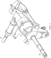
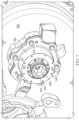
- FIG. 2 shows a cut-away view of a lockout device 20 coupled to a gearbox 10, similar to the gearbox 10 of Figure 1 .
- Lockout device 20 comprises shaft 25, outer collar 30, inner collar 35, housing 40, and cover 45. Screws 48 couple cover 45 to housing 40. While the aircraft is in use (or is otherwise not in a lockout operation) cover 45 will preferably be kept in place to protect housing 40 and shaft 25 from wear and tear. When a user wishes to perform a lockout operation, cover 45 can be removed by removing screws 48. When not in a lockout operation, shaft 25 with teeth 27 will sit to the left (in the view of Figure 2 ) of teeth 58 of drive train 59.
- shaft 25 can be pushed to engage teeth 58.
- Socket head or receiving slot 28 in shaft 25 can receive a socket wrench operated by a user. The user can use the socket wrench to push in shaft 25 to engage teeth 58 with teeth 27, and then to rotate the shaft 25 (and by extension the gearbox 10) so as to torque up gearbox 10 and then restrain further movement during the lockout operation.
- Figure 2 shows a view of lockout device 20 unengaged from teeth 58 of gearbox 10.
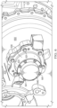
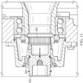
- Figure 3 shows a view of lockout device 20 engaged in teeth 58.
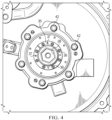
- Figure 4 shows a view of lockout device 20 from outside of gearbox 10.
- Screws 48 are used to couple housing 40 to cover 45 and can be removed when a lockout operation is desired.
- Bolts 42 couple housing to gearbox 10.
- Hex screws 36 couple inner collar 35 to outer collar 30.
- Ring 21 along shaft 25 prevents the leftward movement (in this view) of inner collar 35 along the exterior of shaft 25. Additionally, ring 21 can prevent shaft 25 from being pressed too far into gearbox 10.
- the user may push rightward (in this view) shaft 25 to engage teeth 58. The user can then rotate hex screws 36 (e.g., in a clockwise direction) - this will pull inner collar 35 and outer collar 30 toward each other.
- inner collar 35 will move right with regard to outer collar 30 and vice versa. This motion will force inner collar 35 against the surface of shaft 25 and lock the rotation of shaft 25, and by extension gearbox 10 and drive train 59 because shaft 25 is engaged with teeth 58 via teeth 27.
- the inner collar 35 and outer collar 30 engage each other along line 33, forcing each other in the movements described and thereby causing the locking functionality.
- Hex screws 36 pass through unthreaded holes in inner collar 35 and engage threaded holes in outer collar 30. The rotation of hex screws 36 pulls outer collar 30 and inner collar 35 together and forces inner collar 35 downward against the shaft 25.
- Holes 37 in inner collar 35 can be threaded. Screws or bolts placed here can be screwed in and can engage a flat face of outer collar 30. Rotating the screws/bolts sufficiently can push against the outer collar and move inner collar 35 leftward (from the view of Figure 3 ) and create additional freedom for the rotation of shaft 25.
- the screws or bolts used in holes 37 can be hex screws 36. Hex screws 36 can be removed from the threaded holes in outer collar 30 and threaded into holes 37. Removing hex screws 36 from outer collar 30 and threading them into holes 37 can be part of ending a lockout operation and preparing the gearbox for use.
- O-ring 18 provides sealing protection to keep any fluids or other material from entering gearbox 10 through the lockout device 20.
- Rims 43 of housing 40 can be shaped to abut the right edge (in this view) of outer collar 30 and to restrain rightward movement of outer collar 30 and inner collar 35 along shaft 25.
- Cover 45, or a portion thereof, can be clear or transparent and allow a user to visually inspect a status of lockout device 20.
- an indicator such as a toggle or flipped switch due to placement of the lockout device 20 components, can provide a user an indication of the status of lockout device 20 and/or gearbox 10.
- cover 45 has a ridge 70 that engages slot 72 on shaft 25. While the aircraft is in use and apart from times during lockout operations, ridge 70 and slot 72 hold shaft 25 in place with respect to cover 45 and prevent the engagement of teeth 27 with teeth 58.
- Housing 40 can comprise a slot or ridge for an o-ring 82 for engaging a portion of gearbox 10 to hold housing 40 stationary with respect to gearbox 10. The o-ring can provide an interference fit, sealing, and/or friction, between the housing and the gearbox. A portion of the interior of housing 40 can be hollow so as to save weight.
- Socket head 28 can be hex-shaped for use with a socket wrench when torquing shaft 25 and gearbox 10.
- Shaft 25 can also comprise threaded hole or receiving slot 29 at the bottom of socket head 28.
- Threaded hole 29 can be used with a threaded device to pull out shaft 25 if it gets pressed in too far.
- Socket head 28 can comprise other shapes besides a hexagonal shape. In some embodiments socket head 28 could comprise spline teeth that engage a tool for pulling out shaft 25. Socket head 28 could be square-shaped in other embodiments. Other shapes are possible as well if they allow for torquing the system.
- hex-shaped receiving components or screws, bolts, screw-driver compatible components, Phillips head compatible components, etc. While the Figures show certain embodiments, other shaped components can be used. For example, a hex-shaped socket head 28 is shown. But other embodiments could comprise a pentagonal-shaped head, Phillips screwdriver head, proprietary-shaped head, spline teeth that can be engaged, and other styles. The current disclosure is not limited to a specific set up regarding the use of hex or other shaped or compatible components.
- Step 510 is unscrewing a cover from its coupling to a housing, the housing comprising a hole therethrough and configured to be fixedly coupled to the gearbox.
- Step 520 is uncoupling the cover from a shaft, the shaft configured to pass through the hole and comprising a first plurality of teeth at one end and a socket head on a distal end, the shaft configured to be translatable along its axis, wherein coupling the shaft to the cover prevents the shaft from engaging the drive train.
- Step 530 is manipulating the shaft so as to engage a second plurality of teeth on the drive train with the first plurality of teeth so as to transmit rotation from the shaft to the drive train.
- Step 540 is applying a torque to the drive train by rotating the socket head.
- Step 550 is rotating a plurality of threaded bolts coupled to a plurality of threadless holes in an inner collar and a plurality of threaded holes in an outer collar, the inner collar configured to sit around the shaft and at least partially between the shaft and the housing, the outer collar configured to sit around the shaft and at least partially between the inner collar and the housing, wherein rotating the plurality of threaded bolts can adjust the relative position of the inner collar and the outer collar, wherein as the inner collar and the outer collar are pulled closer together the inner collar is pushed against the shaft and restricts a displacement of the shaft within the hole.
- Figures 6 to 12 can help illustrate additional views of a lockout device embodiment and the performance of a lockout procedure and ending the lockout for use of the aircraft.
- Figure 6 displays lockout device 600, comprising a housing 630 and cover 640, coupled to gearbox 650.
- Bolts 641 couple cover 640 to housing 630.
- Bolts 631 couple housing 630 to gearbox 650.
- threaded bolts 665 can be loosened, which will loosen the grip of inner collar 660 and outer collar 670 on shaft 620.
- shaft 620 can now be pushed axially into gearbox 650 so as to engage gear 655.
- Shaft 620 can comprise teeth 629 that engage gear 655.
- Gear 655 can comprise a portion of a drive train 657. Ring 623 on shaft 620 prevents the shaft 620 from being pressed too far into gearbox 650.
- threaded bolts 665 can be removed from outer collar 670 and be threaded into threaded holes 667. Using the threaded bolts 665 in threaded holes 667 will cause the tip of the threaded bolts 665 to press against a flat surface of outer collar 670 and thereby press inner collar 660 and outer collar 670 apart from each other and reduce grip on the shaft 620. Shaft 620 can now be pulled away from gear 655, allowing the gearbox 650 and drive train 657 to be operable for flight or other vehicle usage.
- Threaded bolts 665 can be retrieved from threaded holes 667 and reinserted into the inner collar 660 and outer collar 670 and tightened to "lock" the shaft in the unengaged position.
- Collar 640 ( Figure 12 ) can then be reattached to housing 630.
- Coupling 649 between collar 640 and shaft 620 can help hold shaft 620 in its locked and unengaged position so that it does not touch or engage gear 655 or drive train 657 during operation.
Landscapes
- Engineering & Computer Science (AREA)
- General Engineering & Computer Science (AREA)
- Mechanical Engineering (AREA)
- General Details Of Gearings (AREA)
Claims (14)
- Verriegelungsvorrichtung (20) für ein Getriebe (10), umfassend:ein Gehäuse (40), das ein Loch durch dieses hindurch umfasst und dazu konfiguriert ist, fest mit dem Getriebe (10) gekoppelt zu sein;eine Welle (25), die lösbar an das Gehäuse gekoppelt und dazu konfiguriert ist, durch das Loch hindurchzugehen, wobei die Welle eine Vielzahl von Zähnen (27) an einem Ende und einen Aufnahmeschlitz (28) an einem distalen Ende umfasst, wobei die Vielzahl von Zähnen dazu konfiguriert ist, mit einem Abschnitt eines Antriebsstrangs (59) innerhalb des Getriebes in Eingriff zu kommen und eine Drehung von der Welle auf den Antriebsstrang zu übertragen;einen inneren Kragen (35), der dazu konfiguriert ist, um die Welle herum und zumindest teilweise zwischen der Welle und dem Gehäuse zu sitzen, dadurch gekennzeichnet, dass der innere Kragen eine Vielzahl gewindeloser Löcher umfasst; und einen äußeren Kragen (30), der dazu konfiguriert ist, um die Welle herum und zumindest teilweise zwischen dem inneren Kragen und dem Gehäuse zu sitzen, wobei der äußere Kragen eine Vielzahl von Gewindelöchern umfasst, die dazu konfiguriert sind, eine Vielzahl von Bolzen (36) aufzunehmen, die durch die Vielzahl gewindeloser Löcher hindurchtreten, wobei durch Drehen der Vielzahl von Bolzen die relative Position des inneren Kragens und des äußeren Kragens eingestellt werden kann, wobei, wenn der innere Kragen und der äußere Kragen enger zusammengezogen werden, der innere Kragen gegen die Welle gedrückt wird und eine Verschiebung der Welle in dem Loch einschränkt.
- Verriegelungsvorrichtung nach Anspruch 1, wobei die Welle einen zweiten Aufnahmeschlitz (29) an einer Unterkante des Aufnahmeschlitzes umfasst.
- Verriegelungsvorrichtung nach Anspruch 2, wobei der zweite Aufnahmeschlitz eine Vielzahl von Gewinden umfasst.
- Verriegelungsvorrichtung nach Anspruch 1, ferner umfassend eine lösbar an das Gehäuse gekoppelte Abdeckung (45), wobei die Welle lösbar an die Abdeckung gekoppelt ist.
- Verriegelungsvorrichtung nach Anspruch 1, wobei der innere Kragen eine zweite Vielzahl von Gewindelöchern (37) umfasst, die dazu konfiguriert sind, einer zweiten Vielzahl von Bolzen (36) zu ermöglichen, durch sie hindurchzutreten und mit einer Oberfläche des äußeren Kragens in Eingriff zu treten.
- Verriegelungsvorrichtung nach Anspruch 1, wobei die Welle einen Ring (21) umfasst, der dazu konfiguriert ist, mit einer Kante des inneren Kragens in Eingriff zu treten und eine weitere Verschiebung der Welle innerhalb des Lochs zu verhindern.
- Verriegelungsvorrichtung nach Anspruch 1, wobei das Gehäuse einen Rand (43) in der Nähe des Lochs umfasst, der dazu konfiguriert ist, eine Verschiebung des äußeren Kragens zu beschränken.
- Verriegelungsvorrichtung nach Anspruch 1, wobei die Welle einen O-Ring (18) umfasst, der dazu konfiguriert ist, einen Spalt zwischen der Welle und dem Gehäuse abzudichten.
- Verfahren (500) zum Durchführen eines Verriegelungsvorgangs zum Festziehen und Verriegeln eines Antriebsstrangs in einem Getriebe (10, 650), wobei das Verfahren Folgendes umfasst:Abnehmen (510) einer Abdeckung (45, 640) von ihrer Kupplung an einem Gehäuse (40, 630), wobei das Gehäuse ein hindurchgehendes Loch umfasst und dazu konfiguriert ist, fest mit dem Getriebe gekoppelt zu sein;Entkoppeln (520) der Abdeckung von einer Welle (25, 620),wobei die Welle dazu konfiguriert ist, durch das Loch zu verlaufen, und eine erste Vielzahl von Zähnen (27, 629) an einem Ende und einen Innensechskant (28, 622) an einem distalen Ende umfasst, wobei die Welle dazu konfiguriert ist, entlang ihrer Achse verschiebbar zu sein, wobei das Koppeln der Welle mit der Abdeckung verhindert, dass die Welle in den Antriebsstrang eingreift;Manipulieren (530) der Welle, sodass eine zweite Vielzahl von Zähnen (58, 655) auf dem Antriebsstrang mit der ersten Vielzahl von Zähnen eingreift, sodass eine Drehung von der Welle auf den Antriebsstrang übertragen wird;Ausüben (540) eines Drehmoments auf den Antriebsstrang durch Drehen des Innensechskants; undDrehen (550) einer Vielzahl von Gewindebolzen (36, 665), die mit einer Vielzahl von gewindelosen Löchern in einem inneren Kragen und eine Vielzahl von Gewindelöchern in einem äußeren Kragen gekoppelt sind, wobei der innere Kragen dazu konfiguriert ist, um die Welle herum und zumindest teilweise zwischen der Welle und dem Gehäuse zu sitzen, wobei der äußere Kragen dazu konfiguriert ist, um die Welle herum und zumindest teilweise zwischen dem inneren Kragen und dem Gehäuse zu sitzen, wobei durch Drehen der Vielzahl von Gewindebolzen die relative Position des inneren Kragens und des äußeren Kragens eingestellt werden kann, wobei, wenn der innere Kragen und der äußere Kragen enger zusammengezogen werden, der innere Kragen gegen die Welle gedrückt wird und eine Verschiebung der Welle in dem Loch einschränkt.
- Verfahren nach Anspruch 9, ferner umfassend, vor dem Manipulieren, Drehen der Vielzahl von Gewindebolzen (36, 665) durch eine zweite Vielzahl von Gewindelöchern (37, 667) in dem inneren Kragen, wobei die zweite Vielzahl von Gewindelöchern (37, 667) dazu konfiguriert ist, der Vielzahl von Gewindebolzen zu ermöglichen, durch sie hindurchzutreten und mit einer flachen Oberfläche des äußeren Kragens in Eingriff zu treten, um den inneren Kragen und den äußeren Kragen voneinander wegzudrücken, wobei, wenn der innere Kragen und der äußere Kragen voneinander weggedrückt werden, der Welle eine größere Bewegungsfreiheit entlang ihrer Achse gegeben wird.
- Verfahren nach Anspruch 9, wobei das Manipulieren der Welle das Bewegen der Welle in Richtung des Antriebsstrangs umfasst, bis der innere Kragen die Bewegung eines die Welle umfassenden Rings (21, 623) stoppt.
- Verfahren nach Anspruch 9, ferner umfassend das erneute Anbringen der Abdeckung an dem Gehäuse.
- Verfahren nach Anspruch 9, ferner umfassend das Überprüfen eines Zustands der Welle durch mindestens eines von: Durchsehen eines transparenten Abschnitts der Abdeckung; Überprüfen eines Anzeigeschalters oder -bodens, der anzeigt, wenn die Abdeckung mit der Welle in Eingriff steht; Überprüfen eines elektrischen Sensors; Überprüfen eines elektrischen Schalters.
- Verfahren nach Anspruch 9, ferner umfassend das Eindrehen eines Gewindeelements in einen Gewindeschlitz an dem Boden des Sockelkopfs und das Herausziehen der Welle aus dem Antriebsstrang mit dem Gewindeelement.
Applications Claiming Priority (1)
| Application Number | Priority Date | Filing Date | Title |
|---|---|---|---|
| US17/885,034 US11859706B1 (en) | 2022-08-10 | 2022-08-10 | Integrated gearbox lockout device |
Publications (2)
| Publication Number | Publication Date |
|---|---|
| EP4328467A1 EP4328467A1 (de) | 2024-02-28 |
| EP4328467B1 true EP4328467B1 (de) | 2025-02-26 |
Family
ID=87047856
Family Applications (1)
| Application Number | Title | Priority Date | Filing Date |
|---|---|---|---|
| EP23181165.4A Active EP4328467B1 (de) | 2022-08-10 | 2023-06-23 | Integrierte getriebesperrvorrichtung |
Country Status (2)
| Country | Link |
|---|---|
| US (3) | US11859706B1 (de) |
| EP (1) | EP4328467B1 (de) |
Families Citing this family (1)
| Publication number | Priority date | Publication date | Assignee | Title |
|---|---|---|---|---|
| US11859706B1 (en) * | 2022-08-10 | 2024-01-02 | Textron Innovations Inc. | Integrated gearbox lockout device |
Family Cites Families (12)
| Publication number | Priority date | Publication date | Assignee | Title |
|---|---|---|---|---|
| US2691541A (en) * | 1949-12-05 | 1954-10-12 | Melba L Benedek | Shaft bushing for mountable machine elements |
| CH582314A5 (de) * | 1974-09-14 | 1976-11-30 | Ringfeder Gmbh | |
| JPS5848788B2 (ja) * | 1979-10-12 | 1983-10-31 | 日本発条株式会社 | 推進力付与装置におけるロツク機構 |
| US4304502A (en) * | 1979-11-15 | 1981-12-08 | Andrew Stratienko | Torque and thrust transmitting bushings |
| US4922599A (en) * | 1989-01-09 | 1990-05-08 | Mark Durfee | Method of converting a four speed manual transmission to a five speed transmission |
| US5042749A (en) * | 1990-04-10 | 1991-08-27 | Sundstrand Corporation | Mechanism for limiting rotation of a rotatably mounted shaft |
| US5286232A (en) * | 1992-04-10 | 1994-02-15 | Borg-Warner Automotive Diversified Transmission Products Corporation | Slip yoke assembly for output of power transmission device |
| US6098753A (en) * | 1998-06-05 | 2000-08-08 | Pratt & Whitney Canada Corp. | System for delivering pressurized lubricant fluids to an interior of a rotating hollow shaft |
| DE102012015012B4 (de) * | 2011-08-06 | 2024-02-15 | Neumayer Tekfor Engineering Gmbh | Parksperre |
| US20150102033A1 (en) | 2013-10-11 | 2015-04-16 | Silgan Plastics Llc | Container with high density molecular weight polyethylene moisture barrier layer |
| GB2591158B (en) * | 2019-10-29 | 2024-02-07 | Zf Steering Systems Poland Sp Z O O | A gearbox assembly for a vehicle |
| US11859706B1 (en) * | 2022-08-10 | 2024-01-02 | Textron Innovations Inc. | Integrated gearbox lockout device |
-
2022
- 2022-08-10 US US17/885,034 patent/US11859706B1/en active Active
-
2023
- 2023-06-23 EP EP23181165.4A patent/EP4328467B1/de active Active
- 2023-12-21 US US18/392,942 patent/US12188548B2/en active Active
-
2024
- 2024-12-19 US US18/987,808 patent/US20250116325A1/en active Pending
Also Published As
| Publication number | Publication date |
|---|---|
| EP4328467A1 (de) | 2024-02-28 |
| US20250116325A1 (en) | 2025-04-10 |
| US12188548B2 (en) | 2025-01-07 |
| US11859706B1 (en) | 2024-01-02 |
| US20240125378A1 (en) | 2024-04-18 |
Similar Documents
| Publication | Publication Date | Title |
|---|---|---|
| US6679361B2 (en) | Emergency facilities for influencing defective constituents of power trains in motor vehicles | |
| US8590417B1 (en) | Trailer landing gear apparatus | |
| US6796385B1 (en) | Fastener driving machine and associated method | |
| EP4328467B1 (de) | Integrierte getriebesperrvorrichtung | |
| CN101204742A (zh) | 钻/起子 | |
| US20120318082A1 (en) | Apparatus for converting a rotational movement into an axial movement | |
| JPS6227520Y2 (de) | ||
| EP4015803B1 (de) | Schnell zugängliches motorrotator-pad | |
| US20060116232A1 (en) | Manually adjustable clutch assembly with visual indicator | |
| EP4443023B1 (de) | Achsanordnung und verfahren zur steuerung der positionierung eines schaltmechanismus | |
| US5609090A (en) | Actuator with protective end cap | |
| US20100314956A1 (en) | Linear actuator | |
| US20190376563A1 (en) | Power screw mechanism with rotation clutch | |
| US4585025A (en) | Mounting for a valve actuator | |
| CN101576128A (zh) | 啮合式离合器 | |
| CN108233606B (zh) | 驱动器的手动超控装置 | |
| WO2021228397A1 (en) | Joint arrangement, electric motor and industrial actuator | |
| WO2019141564A1 (en) | Disk clutch assembly | |
| US12403762B2 (en) | Axle assembly having a shift mechanism | |
| US4655106A (en) | Tube or pipe profiling apparatus | |
| US20250357833A1 (en) | Motor extraction tool and related methods | |
| JPS626984Y2 (de) | ||
| WO2025231504A1 (en) | Adaptor device, retainer means, tool and system | |
| JP3649772B2 (ja) | パワーテークオフ装置 | |
| GB2358895A (en) | Automated power train of a vehicle with emergency control in the event of malfunction |
Legal Events
| Date | Code | Title | Description |
|---|---|---|---|
| PUAI | Public reference made under article 153(3) epc to a published international application that has entered the european phase |
Free format text: ORIGINAL CODE: 0009012 |
|
| STAA | Information on the status of an ep patent application or granted ep patent |
Free format text: STATUS: REQUEST FOR EXAMINATION WAS MADE |
|
| STAA | Information on the status of an ep patent application or granted ep patent |
Free format text: STATUS: EXAMINATION IS IN PROGRESS |
|
| 17P | Request for examination filed |
Effective date: 20230623 |
|
| AK | Designated contracting states |
Kind code of ref document: A1 Designated state(s): AL AT BE BG CH CY CZ DE DK EE ES FI FR GB GR HR HU IE IS IT LI LT LU LV MC ME MK MT NL NO PL PT RO RS SE SI SK SM TR |
|
| 17Q | First examination report despatched |
Effective date: 20240212 |
|
| GRAP | Despatch of communication of intention to grant a patent |
Free format text: ORIGINAL CODE: EPIDOSNIGR1 |
|
| STAA | Information on the status of an ep patent application or granted ep patent |
Free format text: STATUS: GRANT OF PATENT IS INTENDED |
|
| RIC1 | Information provided on ipc code assigned before grant |
Ipc: F16H 57/023 20120101ALN20240911BHEP Ipc: F16H 57/00 20120101ALN20240911BHEP Ipc: F16H 63/34 20060101ALI20240911BHEP Ipc: F16H 61/22 20060101AFI20240911BHEP |
|
| RIC1 | Information provided on ipc code assigned before grant |
Ipc: F16H 57/023 20120101ALN20240916BHEP Ipc: F16H 57/00 20120101ALN20240916BHEP Ipc: F16H 63/34 20060101ALI20240916BHEP Ipc: F16H 61/22 20060101AFI20240916BHEP |
|
| INTG | Intention to grant announced |
Effective date: 20241008 |
|
| GRAS | Grant fee paid |
Free format text: ORIGINAL CODE: EPIDOSNIGR3 |
|
| GRAA | (expected) grant |
Free format text: ORIGINAL CODE: 0009210 |
|
| STAA | Information on the status of an ep patent application or granted ep patent |
Free format text: STATUS: THE PATENT HAS BEEN GRANTED |
|
| AK | Designated contracting states |
Kind code of ref document: B1 Designated state(s): AL AT BE BG CH CY CZ DE DK EE ES FI FR GB GR HR HU IE IS IT LI LT LU LV MC ME MK MT NL NO PL PT RO RS SE SI SK SM TR |
|
| REG | Reference to a national code |
Ref country code: GB Ref legal event code: FG4D |
|
| REG | Reference to a national code |
Ref country code: CH Ref legal event code: EP |
|
| P01 | Opt-out of the competence of the unified patent court (upc) registered |
Free format text: CASE NUMBER: APP_5613/2025 Effective date: 20250203 |
|
| REG | Reference to a national code |
Ref country code: DE Ref legal event code: R096 Ref document number: 602023002177 Country of ref document: DE |
|
| REG | Reference to a national code |
Ref country code: IE Ref legal event code: FG4D |
|
| REG | Reference to a national code |
Ref country code: NL Ref legal event code: MP Effective date: 20250226 |
|
| PG25 | Lapsed in a contracting state [announced via postgrant information from national office to epo] |
Ref country code: RS Free format text: LAPSE BECAUSE OF FAILURE TO SUBMIT A TRANSLATION OF THE DESCRIPTION OR TO PAY THE FEE WITHIN THE PRESCRIBED TIME-LIMIT Effective date: 20250526 |
|
| PG25 | Lapsed in a contracting state [announced via postgrant information from national office to epo] |
Ref country code: FI Free format text: LAPSE BECAUSE OF FAILURE TO SUBMIT A TRANSLATION OF THE DESCRIPTION OR TO PAY THE FEE WITHIN THE PRESCRIBED TIME-LIMIT Effective date: 20250226 |
|
| PG25 | Lapsed in a contracting state [announced via postgrant information from national office to epo] |
Ref country code: PL Free format text: LAPSE BECAUSE OF FAILURE TO SUBMIT A TRANSLATION OF THE DESCRIPTION OR TO PAY THE FEE WITHIN THE PRESCRIBED TIME-LIMIT Effective date: 20250226 |
|
| PGFP | Annual fee paid to national office [announced via postgrant information from national office to epo] |
Ref country code: DE Payment date: 20250627 Year of fee payment: 3 |
|
| PG25 | Lapsed in a contracting state [announced via postgrant information from national office to epo] |
Ref country code: ES Free format text: LAPSE BECAUSE OF FAILURE TO SUBMIT A TRANSLATION OF THE DESCRIPTION OR TO PAY THE FEE WITHIN THE PRESCRIBED TIME-LIMIT Effective date: 20250226 |
|
| REG | Reference to a national code |
Ref country code: LT Ref legal event code: MG9D |
|
| PG25 | Lapsed in a contracting state [announced via postgrant information from national office to epo] |
Ref country code: NO Free format text: LAPSE BECAUSE OF FAILURE TO SUBMIT A TRANSLATION OF THE DESCRIPTION OR TO PAY THE FEE WITHIN THE PRESCRIBED TIME-LIMIT Effective date: 20250526 Ref country code: IS Free format text: LAPSE BECAUSE OF FAILURE TO SUBMIT A TRANSLATION OF THE DESCRIPTION OR TO PAY THE FEE WITHIN THE PRESCRIBED TIME-LIMIT Effective date: 20250626 |
|
| PG25 | Lapsed in a contracting state [announced via postgrant information from national office to epo] |
Ref country code: NL Free format text: LAPSE BECAUSE OF FAILURE TO SUBMIT A TRANSLATION OF THE DESCRIPTION OR TO PAY THE FEE WITHIN THE PRESCRIBED TIME-LIMIT Effective date: 20250226 |
|
| PG25 | Lapsed in a contracting state [announced via postgrant information from national office to epo] |
Ref country code: HR Free format text: LAPSE BECAUSE OF FAILURE TO SUBMIT A TRANSLATION OF THE DESCRIPTION OR TO PAY THE FEE WITHIN THE PRESCRIBED TIME-LIMIT Effective date: 20250226 |
|
| PG25 | Lapsed in a contracting state [announced via postgrant information from national office to epo] |
Ref country code: LV Free format text: LAPSE BECAUSE OF FAILURE TO SUBMIT A TRANSLATION OF THE DESCRIPTION OR TO PAY THE FEE WITHIN THE PRESCRIBED TIME-LIMIT Effective date: 20250226 Ref country code: PT Free format text: LAPSE BECAUSE OF FAILURE TO SUBMIT A TRANSLATION OF THE DESCRIPTION OR TO PAY THE FEE WITHIN THE PRESCRIBED TIME-LIMIT Effective date: 20250626 |
|
| PGFP | Annual fee paid to national office [announced via postgrant information from national office to epo] |
Ref country code: FR Payment date: 20250625 Year of fee payment: 3 |
|
| PG25 | Lapsed in a contracting state [announced via postgrant information from national office to epo] |
Ref country code: GR Free format text: LAPSE BECAUSE OF FAILURE TO SUBMIT A TRANSLATION OF THE DESCRIPTION OR TO PAY THE FEE WITHIN THE PRESCRIBED TIME-LIMIT Effective date: 20250527 Ref country code: BG Free format text: LAPSE BECAUSE OF FAILURE TO SUBMIT A TRANSLATION OF THE DESCRIPTION OR TO PAY THE FEE WITHIN THE PRESCRIBED TIME-LIMIT Effective date: 20250226 |
|
| REG | Reference to a national code |
Ref country code: AT Ref legal event code: MK05 Ref document number: 1770903 Country of ref document: AT Kind code of ref document: T Effective date: 20250226 |
|
| PG25 | Lapsed in a contracting state [announced via postgrant information from national office to epo] |
Ref country code: SE Free format text: LAPSE BECAUSE OF FAILURE TO SUBMIT A TRANSLATION OF THE DESCRIPTION OR TO PAY THE FEE WITHIN THE PRESCRIBED TIME-LIMIT Effective date: 20250226 |
|
| PG25 | Lapsed in a contracting state [announced via postgrant information from national office to epo] |
Ref country code: SM Free format text: LAPSE BECAUSE OF FAILURE TO SUBMIT A TRANSLATION OF THE DESCRIPTION OR TO PAY THE FEE WITHIN THE PRESCRIBED TIME-LIMIT Effective date: 20250226 |
|
| PG25 | Lapsed in a contracting state [announced via postgrant information from national office to epo] |
Ref country code: DK Free format text: LAPSE BECAUSE OF FAILURE TO SUBMIT A TRANSLATION OF THE DESCRIPTION OR TO PAY THE FEE WITHIN THE PRESCRIBED TIME-LIMIT Effective date: 20250226 |
|
| PG25 | Lapsed in a contracting state [announced via postgrant information from national office to epo] |
Ref country code: IT Free format text: LAPSE BECAUSE OF FAILURE TO SUBMIT A TRANSLATION OF THE DESCRIPTION OR TO PAY THE FEE WITHIN THE PRESCRIBED TIME-LIMIT Effective date: 20250226 |
|
| PG25 | Lapsed in a contracting state [announced via postgrant information from national office to epo] |
Ref country code: AT Free format text: LAPSE BECAUSE OF FAILURE TO SUBMIT A TRANSLATION OF THE DESCRIPTION OR TO PAY THE FEE WITHIN THE PRESCRIBED TIME-LIMIT Effective date: 20250226 |
|
| PG25 | Lapsed in a contracting state [announced via postgrant information from national office to epo] |
Ref country code: EE Free format text: LAPSE BECAUSE OF FAILURE TO SUBMIT A TRANSLATION OF THE DESCRIPTION OR TO PAY THE FEE WITHIN THE PRESCRIBED TIME-LIMIT Effective date: 20250226 Ref country code: CZ Free format text: LAPSE BECAUSE OF FAILURE TO SUBMIT A TRANSLATION OF THE DESCRIPTION OR TO PAY THE FEE WITHIN THE PRESCRIBED TIME-LIMIT Effective date: 20250226 |
|
| PG25 | Lapsed in a contracting state [announced via postgrant information from national office to epo] |
Ref country code: RO Free format text: LAPSE BECAUSE OF FAILURE TO SUBMIT A TRANSLATION OF THE DESCRIPTION OR TO PAY THE FEE WITHIN THE PRESCRIBED TIME-LIMIT Effective date: 20250226 |
|
| PG25 | Lapsed in a contracting state [announced via postgrant information from national office to epo] |
Ref country code: SK Free format text: LAPSE BECAUSE OF FAILURE TO SUBMIT A TRANSLATION OF THE DESCRIPTION OR TO PAY THE FEE WITHIN THE PRESCRIBED TIME-LIMIT Effective date: 20250226 |
|
| REG | Reference to a national code |
Ref country code: DE Ref legal event code: R097 Ref document number: 602023002177 Country of ref document: DE |
|
| PLBE | No opposition filed within time limit |
Free format text: ORIGINAL CODE: 0009261 |
|
| STAA | Information on the status of an ep patent application or granted ep patent |
Free format text: STATUS: NO OPPOSITION FILED WITHIN TIME LIMIT |
|
| PG25 | Lapsed in a contracting state [announced via postgrant information from national office to epo] |
Ref country code: MC Free format text: LAPSE BECAUSE OF FAILURE TO SUBMIT A TRANSLATION OF THE DESCRIPTION OR TO PAY THE FEE WITHIN THE PRESCRIBED TIME-LIMIT Effective date: 20250226 |
|
| 26N | No opposition filed |
Effective date: 20251127 |