EP4328370A1 - Washing machine and control method and device thereof - Google Patents
Washing machine and control method and device thereof Download PDFInfo
- Publication number
- EP4328370A1 EP4328370A1 EP21938965.7A EP21938965A EP4328370A1 EP 4328370 A1 EP4328370 A1 EP 4328370A1 EP 21938965 A EP21938965 A EP 21938965A EP 4328370 A1 EP4328370 A1 EP 4328370A1
- Authority
- EP
- European Patent Office
- Prior art keywords
- steam
- water
- inner tub
- tub
- washing machine
- Prior art date
- Legal status (The legal status is an assumption and is not a legal conclusion. Google has not performed a legal analysis and makes no representation as to the accuracy of the status listed.)
- Granted
Links
Images



Classifications
-
- D—TEXTILES; PAPER
- D06—TREATMENT OF TEXTILES OR THE LIKE; LAUNDERING; FLEXIBLE MATERIALS NOT OTHERWISE PROVIDED FOR
- D06F—LAUNDERING, DRYING, IRONING, PRESSING OR FOLDING TEXTILE ARTICLES
- D06F33/00—Control of operations performed in washing machines or washer-dryers
- D06F33/50—Control of washer-dryers characterised by the purpose or target of the control
- D06F33/52—Control of the operational steps, e.g. optimisation or improvement of operational steps depending on the condition of the laundry
-
- D—TEXTILES; PAPER
- D06—TREATMENT OF TEXTILES OR THE LIKE; LAUNDERING; FLEXIBLE MATERIALS NOT OTHERWISE PROVIDED FOR
- D06F—LAUNDERING, DRYING, IRONING, PRESSING OR FOLDING TEXTILE ARTICLES
- D06F33/00—Control of operations performed in washing machines or washer-dryers
- D06F33/30—Control of washing machines characterised by the purpose or target of the control
- D06F33/32—Control of operational steps, e.g. optimisation or improvement of operational steps depending on the condition of the laundry
- D06F33/34—Control of operational steps, e.g. optimisation or improvement of operational steps depending on the condition of the laundry of water filling
-
- D—TEXTILES; PAPER
- D06—TREATMENT OF TEXTILES OR THE LIKE; LAUNDERING; FLEXIBLE MATERIALS NOT OTHERWISE PROVIDED FOR
- D06F—LAUNDERING, DRYING, IRONING, PRESSING OR FOLDING TEXTILE ARTICLES
- D06F33/00—Control of operations performed in washing machines or washer-dryers
- D06F33/30—Control of washing machines characterised by the purpose or target of the control
- D06F33/32—Control of operational steps, e.g. optimisation or improvement of operational steps depending on the condition of the laundry
- D06F33/36—Control of operational steps, e.g. optimisation or improvement of operational steps depending on the condition of the laundry of washing
-
- D—TEXTILES; PAPER
- D06—TREATMENT OF TEXTILES OR THE LIKE; LAUNDERING; FLEXIBLE MATERIALS NOT OTHERWISE PROVIDED FOR
- D06F—LAUNDERING, DRYING, IRONING, PRESSING OR FOLDING TEXTILE ARTICLES
- D06F34/00—Details of control systems for washing machines, washer-dryers or laundry dryers
- D06F34/04—Signal transfer or data transmission arrangements
-
- D—TEXTILES; PAPER
- D06—TREATMENT OF TEXTILES OR THE LIKE; LAUNDERING; FLEXIBLE MATERIALS NOT OTHERWISE PROVIDED FOR
- D06F—LAUNDERING, DRYING, IRONING, PRESSING OR FOLDING TEXTILE ARTICLES
- D06F39/00—Details of washing machines not specific to a single type of machines covered by groups D06F9/00 - D06F27/00
- D06F39/40—Steam generating arrangements
-
- D—TEXTILES; PAPER
- D06—TREATMENT OF TEXTILES OR THE LIKE; LAUNDERING; FLEXIBLE MATERIALS NOT OTHERWISE PROVIDED FOR
- D06F—LAUNDERING, DRYING, IRONING, PRESSING OR FOLDING TEXTILE ARTICLES
- D06F2103/00—Parameters monitored or detected for the control of domestic laundry washing machines, washer-dryers or laundry dryers
- D06F2103/18—Washing liquid level
-
- D—TEXTILES; PAPER
- D06—TREATMENT OF TEXTILES OR THE LIKE; LAUNDERING; FLEXIBLE MATERIALS NOT OTHERWISE PROVIDED FOR
- D06F—LAUNDERING, DRYING, IRONING, PRESSING OR FOLDING TEXTILE ARTICLES
- D06F2105/00—Systems or parameters controlled or affected by the control systems of washing machines, washer-dryers or laundry dryers
- D06F2105/02—Water supply
-
- D—TEXTILES; PAPER
- D06—TREATMENT OF TEXTILES OR THE LIKE; LAUNDERING; FLEXIBLE MATERIALS NOT OTHERWISE PROVIDED FOR
- D06F—LAUNDERING, DRYING, IRONING, PRESSING OR FOLDING TEXTILE ARTICLES
- D06F2105/00—Systems or parameters controlled or affected by the control systems of washing machines, washer-dryers or laundry dryers
- D06F2105/28—Electric heating
-
- D—TEXTILES; PAPER
- D06—TREATMENT OF TEXTILES OR THE LIKE; LAUNDERING; FLEXIBLE MATERIALS NOT OTHERWISE PROVIDED FOR
- D06F—LAUNDERING, DRYING, IRONING, PRESSING OR FOLDING TEXTILE ARTICLES
- D06F2105/00—Systems or parameters controlled or affected by the control systems of washing machines, washer-dryers or laundry dryers
- D06F2105/46—Drum speed; Actuation of motors, e.g. starting or interrupting
- D06F2105/48—Drum speed
-
- D—TEXTILES; PAPER
- D06—TREATMENT OF TEXTILES OR THE LIKE; LAUNDERING; FLEXIBLE MATERIALS NOT OTHERWISE PROVIDED FOR
- D06F—LAUNDERING, DRYING, IRONING, PRESSING OR FOLDING TEXTILE ARTICLES
- D06F25/00—Washing machines with receptacles, e.g. perforated, having a rotary movement, e.g. oscillatory movement, the receptacle serving both for washing and for centrifugally separating water from the laundry and having further drying means, e.g. using hot air
-
- Y—GENERAL TAGGING OF NEW TECHNOLOGICAL DEVELOPMENTS; GENERAL TAGGING OF CROSS-SECTIONAL TECHNOLOGIES SPANNING OVER SEVERAL SECTIONS OF THE IPC; TECHNICAL SUBJECTS COVERED BY FORMER USPC CROSS-REFERENCE ART COLLECTIONS [XRACs] AND DIGESTS
- Y02—TECHNOLOGIES OR APPLICATIONS FOR MITIGATION OR ADAPTATION AGAINST CLIMATE CHANGE
- Y02B—CLIMATE CHANGE MITIGATION TECHNOLOGIES RELATED TO BUILDINGS, e.g. HOUSING, HOUSE APPLIANCES OR RELATED END-USER APPLICATIONS
- Y02B40/00—Technologies aiming at improving the efficiency of home appliances, e.g. induction cooking or efficient technologies for refrigerators, freezers or dish washers
Definitions
- the present disclosure relates to, but is not limited to, the field of electrical appliances, and more particularly to, but not limited to, a washing machine and a control method and apparatus thereof.
- Some washing machines have a steam washing mode.
- the steam washing mode when the washing machine runs a steam program, water needs to be firstly fed into the washing machine. However, during the feeding of water into the washing machine, water flows into an inner tub through a through hole at the inner tub of the washing machine to wet clothes, causing the clothes to be aggregated, which is unfavorable for absorption of the steam by the clothes.
- the washing machine may include an inner tub, a heating device, and an outer tub arranged outside the inner tub.
- the heating device is configured to heat water entering the outer tub.
- the method may include: in response to a predetermined steam program being started, feeding water into the outer tub, and controlling the inner tub of the washing machine to rotate at a first rotational speed r1; stopping the feeding of water in response to a water level in the outer tub rising to a first predetermined water level; and controlling the heating device to perform heating to generate steam, and treating clothes in the inner tub with the steam.
- the control device may include a first processor and a first computer readable storage medium.
- the first computer readable storage medium has instructions stored thereon. The instructions implement, when executed by the first processor, the control method as described above.
- the washing machine may include an inner tub, a heating device, an outer tub arranged outside the inner tub, and the control device as described above.
- the heating device is configured to heat water entering the outer tub to generate steam.
- the inner tub has a through hole.
- the through hole is configured to provide a passage for allowing the stem to enter the inner tub.
- the outer tub is connected to a water inlet port.
- Embodiments of the present disclosure provide a control method of a washing machine.
- the washing machine may include an inner tub, a heating device, and an outer tub arranged outside the inner tub.
- the heating device is configured to heat water entering the outer tub.
- the method may include operations at blocks S101 to S103.
- the feeding of water is stopped in response to a water feeding level in the outer tub reaching a first predetermined water level.
- the heating device is controlled to perform heating to generate steam, and clothes in the inner tub are treated with the steam.
- the washing machine may include a heating device 7, an inner tub 5, and an outer tub 6 arranged outside the inner tub 5.
- the heating device 7 is configured to heat water entering the outer tub 6 to generate steam.
- the heating device 7 may be located between the inner tub 5 and the outer tub 6.
- the heating device 7 is disposed between a bottom of the inner tub and a bottom of the outer tub.
- the inner tub may have one or more through holes. The through hole is configured to provide a passage for allowing the steam generated between the inner tub 5 and the outer tub 6 to enter the inner tub 5.
- the outer tub 6 may be connected to a water inlet port to feed water into the outer tub through the water inlet port.
- a steam generator may be used for steam washing by the washing machine.
- the use of the steam generator results in high costs.
- the steam generator has disadvantages such as poor manufacturing and poor reliability.
- user's using effect is not significant.
- water needs to be first fed into the outer tub before the steam is generated.
- the inner tub may be controlled to rotate synchronously.
- a rotational speed of the inner tub may be the first rotational speed r1.
- the first rotational speed r1 during the feeding of water may be a high rotational speed.
- water can be thrown off due to rotation of the inner tub at the high rotational speed even if water falls onto an outer wall of the inner tub during the feeding of water.
- it is possible to prevent water flow from smoothly entering the inner tub through the through hole to wet the clothes inside the inner tub.
- the water flow can be effectively prevented from entering the inner tub, thus avoiding the wetting of the clothes by the water flow. Moreover, many problems potentially occurring as described in the above analysis can be also avoided. Therefore, with the solution according to the embodiments of the present disclosure, the problem in the steam washing can be solved by simply increasing the rotational speed of the inner tub during the feeding of water.
- a specific value of the first rotational speed r1 may be defined based on different types of washing machines, different capacities, different motor configurations, and different requirements, and the present disclosure is not limited in this regard.
- a water level detection device may be provided in the outer tub.
- a water level in the outer tub may be detected in real time by the water level detection device during the feeding of water.
- the water level detection device may be any existing water level detection device that can be implemented.
- a specific implementation manner of the water level detection device is not limited in the present disclosure.
- a corresponding water inlet valve may be controlled to be closed to stop the feeding of water into the outer tub.
- a height of the first predetermined water level is smaller than a vertical distance between a bottom of the inner tub and a bottom of the outer tub.
- a vertical distance d between the bottom of the inner tub and the bottom of the outer tub may be used as a water level threshold, or 2d/3-3d/4 may be used as the water level threshold to provide an allowance.
- the heating device may be controlled to be switched on after the feeding of water is stopped or at a predetermined time before the feeding of water is stopped, to heat water in the outer tub to gradually generate the steam.
- the heating device may be a heating pipe, a heating plate, or the like.
- a specific implementation form, an arrangement position, an arrangement quantity, model selection, or heating power of the heating device are not limited herein and may be defined by the heating device itself as desired.
- the method further includes: controlling, during the heating of the heating device, the inner tub to rotate at a second rotational speed r2 to disperse the clothes in the inner tub to generate the steam.
- the second rotational speed r2 is smaller than the first rotational speed r1.
- the method may include operations at blocks S201 to S203.
- the feeding of water is stopped in response to the water feeding level in the outer tub reaching the first predetermined water level.
- the heating device between the inner tub and the outer tub is controlled to perform the heating to generate the steam, and the inner tub of the washing machine is controlled to rotate at the second rotational speed r2 to disperse the clothes in the inner tub.
- the second rotational speed r2 may be smaller than the first rotational speed r1.
- the inner tub may still be controlled to rotate at this time, and the rotational speed of the inner tub in this case may be a low rotational speed, for example, the second rotational speed r2 smaller than the first rotational speed r1. Since no more water is fed at this time, there is no concern about the fed water flow entering the inner tub to wet the clothes in the inner tub. In this case, rotating the inner tub at the low rotational speed is to allow the generated steam to enter the inner tub through the through hole better, thereby preventing the steam from being blocked outside the inner tub due to too fast rotational speed of the inner tub.
- a specific value of the second rotational speed r2 may be defined based on different types of washing machines, different capacities, different motor configurations, and different requirements, and the present disclosure is not limited in this regard.
- the inner tub when rotating at a low rotational speed, may rotate alternatively in a clockwise rotational direction and a counterclockwise rotational direction. During the alternate rotation, the inner tub may first rotate by one or more revolutions in the clockwise rotational direction, and then rotate by one or more revolutions in the counterclockwise rotational direction.
- the method may also include: detecting, from beginning of the heating to expiry of a predetermined steam generation duration (or a predetermined heating duration), whether the water level in the outer tub has dropped to a second predetermined water level in real time; continuing the heating to generate the steam when the water level in the outer tub has not yet reached the second predetermined water level; and feeding water into the outer tub again in response to the water level in the outer tub dropping to the second predetermined water level.
- a predetermined steam generation duration or a predetermined heating duration
- the rotational speed of the inner tub is still increased during the feeding of water, allowing the inner tub to rotate at a high rotational speed during the feeding of water. After the feeding of water is completed, the rotational speed of the inner tub may be lowered again.
- the rotational speed of the inner tub may be increased to a third rotational speed when water is fed into the outer tub again.
- the third rotational speed may be greater than the second rotational speed.
- a specific value of the third rotational speed may be defined based on different types of washing machines, different capacities, different motor configurations, and different requirements, and the present disclosure is not limited in this regard.
- the third rotational speed may be set to be the same as, greater or smaller than the first rotational speed.
- the water level of the outer tub is still limited by the first predetermined water level.
- the height of the first predetermined water level may still be smaller than the vertical distance d between the bottom of the inner tub and the bottom of the outer tub.
- the washing machine may also include a drying system 9.
- a space between the inner tub 5 and the outer tub 6 of the washing machine may be in communication with the drying system 9.
- the method may also include: during the heating of the heating device to generate the steam, introducing the generated steam into the drying system to perform secondary heating on the introduced steam in the drying system.
- the drying system 9 may be disposed at an upper part of the outer tub 6.
- the space between the inner tub 5 and the outer tub 6 may be in communication with the drying system 9, allowing the generated steam to move upwards to enter the drying system 9 through a communication channel.
- the washing machine may also include a connection structure 8.
- the connection structure 8 may have an air outlet 81, a water inlet 82, and a water outlet 83.
- the drying system 9 may have a drying channel 91.
- the inner tub 5 may be connected to the drying channel 91.
- connection structure 8 is constructed to connect the space between the inner tub 5 and the outer tub 6 with the drying channel 91 of the drying system 9 through the water outlet 83 and the air outlet 81, be connected to a water inlet pipeline 10 for supplying water to the washing machine through the water inlet 82, and be connected to the outer tub 6 of the washing machine through the water outlet 83. That is, the water inlet 82 of the connection structure 8 is in communication with the water inlet pipeline 10, the water outlet 83 is in communication with the outer tub 6, and the air outlet 81 is in communication with the drying channel 91.
- the air outlet 81, the water inlet 82, and the water outlet 83 may be in communication with each other.
- Water is fed into the outer tub 6 through the water inlet 82 and the water outlet 83 (a flow direction of the water is illustrated in a linear arrow of FIG. 8 ).
- Steam rising to a top of the outer tub 6 enters the drying channel 91 through the air outlet 81 and the water outlet 83 (a flow direction of the steam is illustrated in a curve arrow of FIG. 8 ).
- a hot drying program may be executed to heat the steam again.
- a drying temperature may be reasonably controlled and may not be too high.
- a drying fan 92 may also be disposed in the drying channel 91.
- the drying fan 92 in order to quickly introduce the steam into the drying channel 91, the drying fan 92 may be started. Moreover, a rotational speed of the drying fan 92 may be reasonably controlled.
- introducing the generated steam into the drying system to perform the secondary heating on the steam includes: starting the drying fan 92 during the generation of the steam to allow the drying fan 92 to suck the steam into the drying channel 91 through the water outlet 83 and the air outlet 81 of the connection structure 8 and heat the steam in the drying channel 91. In this way, the secondary heating of the steam is implemented.
- the method may also include: blowing the secondary-heated steam into the inner tub through rotation of the drying fan 9.
- the drying channel 91 is in communication with the inner tub 5, by providing the drying fan 92 with an appropriate rotational speed and rotational direction, the generated steam can be sucked into the drying channel 91 from the outer tub 6, and then the steam is delivered into the inner tub 5 after being subject the secondary heating in the drying channel 91.
- a low-cost and double-steam effect can be achieved through the washing machine with the structure as described above.
- the washing machine runs the steam program
- water is first fed into the outer tub, and the inner tub rotates during the feeding of water.
- the inner tub rotates at the rotational speed of r1.
- the heating device starts performing the heating to generate steam gradually.
- the inner tub also synchronously rotates to disperse the clothes. In this way, it is convenient to increasing the contact area of the clothes with the steam, thereby enhancing the wrinkle removal effect.
- the inner tub rotates at the rotational speed of r2.
- the water level will drop. When the water level drops to a predetermined water level, water is fed again.
- r1 > r2 indicates that the rotational speed of the inner tub during the feeding of water is greater than the rotational speed of the inner tub during the generation of the steam. During the feeding of water, the rotational speed of the inner tub is high. Therefore, a large operation speed of the inner tub can be ensured, allowing for difficult flowing of the water into the inner tub.
- An embodiment of the present disclosure also provides a control device 1 of a washing machine.
- the control device 1 may include a first processor 11 and a first computer readable storage medium 12.
- the first computer readable storage medium 12 has instructions stored thereon. When the instructions are executed by the first processor 11, the method according to any one of the above exemplary embodiments can be implemented.
- any embodiment of the above control method may be applied in the embodiments of the control device 1 of the washing machine, and the detailed description thereof will be omitted herein.
- the washing machine 2 may include an inner tub 5, a heating device 7, an outer tub 6 arranged outside the inner tub 5, and the control device 1 as described above.
- the heating device 7 may be arranged between the inner tub 5 and the outer tub 6.
- the heating device 7 is configured to heat water entering the outer tub 6 to generate steam.
- the inner tub 5 has a through hole.
- the through hole is configured to provide a passage for allowing the stem to enter the inner tub 5.
- the outer tub 6 is connected to a water inlet port.
- any embodiment of the above control method of the washing machine may be applied in the embodiments of the washing machine 2, and the detailed description thereof will be omitted herein.
- the washing machine also includes a connection structure 8 and a drying system 9.
- the connection structure 8 may have an air outlet 81, a water inlet 82, and a water outlet 83.
- the water outlet 83 may be used as the water inlet port.
- the drying system 9 may have a drying channel 91 and a drying fan 92 disposed in the drying channel 91.
- the inner tub 5 is connected to the drying channel 91.
- connection structure 8 is constructed to connect a space between the inner tub 5 and the outer tub 6 with the drying channel 91 through the water outlet 83 and the air outlet 81, and be connected to the water inlet pipeline 10 through the water inlet 82 and to the outer tub 6 through the water outlet 83.
- the drying fan 92 is configured to suck the steam into the drying channel 91 and blow the heated steam into the inner tub 5.
- any one of the embodiments of the control method of the washing machine described above may be applied in the embodiments of the washing machine 4, and detailed description thereof will be omitted herein.
- orientation indication such as up, down, left, right, front, and back, etc.
- the orientation indication is only used to explain a relative position relationship, a motion situation, etc. among components in a predetermined posture as shown in the drawings.
- the orientation indication is also changed accordingly.
- connection to may be a fixed connection or a detachable connection or connection as one piece; a mechanical connection or an electrical connection; a direct connection or an indirect connection through an intermediate; internal communication of two components or an interaction relationship between two components, unless otherwise clearly defined.
- fix may be a fixed connection or a detachable connection or connection as one piece; a mechanical connection or an electrical connection; a direct connection or an indirect connection through an intermediate; internal communication of two components or an interaction relationship between two components, unless otherwise clearly defined.
- the specific meaning of the above-mentioned terms in the embodiments of the present disclosure may be understood according to specific circumstances.
- all or some of the steps, systems, and functional modules/units of the apparatus in the method as disclosed above may be implemented as software, firmware, hardware, and appropriate combinations thereof.
- the division between the functional modules/units mentioned in the above description does not necessarily correspond to the division of physical components.
- one physical component may have a plurality of functions, or one function or one step may be performed cooperatively by several physical components.
- Some or all components may be implemented as software executed by a processor such as a digital signal processor or microprocessor, may be implemented as hardware, or may be implemented as an integrated circuit such as an application-specific integrated circuit.
- a software may be distributed on a computer readable medium.
- the computer readable medium may include a computer storage medium (or a non-transitory medium) and a communication medium (or a transitory medium).
- a computer storage medium includes volatile and non-volatile, removable and non-removable medium implemented in any method or technology for storing information, such as computer readable instructions, data structures, program modules, or other data.
- the computer storage medium may include, but is not limited to, RAM, ROM, EEPROM, flash memory or other memory technology, CD-ROM, digital versatile disks (DVD) or other optical disk storage, magnetic cassettes, magnetic tape, magnetic disk storage or other magnetic storage devices, or any other medium that may be used to store desired information and be accessed by a computer.
- communication medium typically contains computer readable instructions, data structures, program modules, or other data in modulated data signals such as carriers or other transport mechanisms, and may include any information delivery medium.
- communication medium typically contains computer readable instructions, data structures, program modules, or other data in modulated data signals such as carriers or other transport mechanisms, and may include any information delivery medium.
- the specification may have presented the method and/or process as a particular sequence of steps. However, the method or process should not be limited to steps in a particular order as described herein, without relying on the particular order of the steps described herein. As understood by those of ordinary skill in the art, other step sequences are possible. Therefore, the specific order of the steps set forth in the specification should not be construed as limiting the claims. In addition, the claims for this method and/or process should not be limited to the steps in which they are performed in the described order. Those skilled in the art may readily understand that these orders may be varied and remain within the spirit and scope of the embodiments of the present disclosure.
Landscapes
- Engineering & Computer Science (AREA)
- Textile Engineering (AREA)
- Computer Networks & Wireless Communication (AREA)
- Control Of Washing Machine And Dryer (AREA)
- Main Body Construction Of Washing Machines And Laundry Dryers (AREA)
- Detail Structures Of Washing Machines And Dryers (AREA)
Abstract
Description
- The present disclosure relates to, but is not limited to, the field of electrical appliances, and more particularly to, but not limited to, a washing machine and a control method and apparatus thereof.
- Some washing machines have a steam washing mode. In the steam washing mode, when the washing machine runs a steam program, water needs to be firstly fed into the washing machine. However, during the feeding of water into the washing machine, water flows into an inner tub through a through hole at the inner tub of the washing machine to wet clothes, causing the clothes to be aggregated, which is unfavorable for absorption of the steam by the clothes.
- The following description is a summary of the subject matter described in detail herein. This summary is not intended to limit the scope of the claims.
- Provided is a control method of a washing machine. The washing machine may include an inner tub, a heating device, and an outer tub arranged outside the inner tub. The heating device is configured to heat water entering the outer tub. The method may include: in response to a predetermined steam program being started, feeding water into the outer tub, and controlling the inner tub of the washing machine to rotate at a first rotational speed r1; stopping the feeding of water in response to a water level in the outer tub rising to a first predetermined water level; and controlling the heating device to perform heating to generate steam, and treating clothes in the inner tub with the steam.
- Provided is a control device of a washing machine. The control device may include a first processor and a first computer readable storage medium. The first computer readable storage medium has instructions stored thereon. The instructions implement, when executed by the first processor, the control method as described above.
- Provided is a washing machine. The washing machine may include an inner tub, a heating device, an outer tub arranged outside the inner tub, and the control device as described above. The heating device is configured to heat water entering the outer tub to generate steam. The inner tub has a through hole. The through hole is configured to provide a passage for allowing the stem to enter the inner tub. The outer tub is connected to a water inlet port.
- Other aspects may be apparent upon reading and understanding the drawings and detailed description.
- The drawings are used for providing a further understanding of technical solutions of the present disclosure, and constitute a part of the specification. In addition, the drawings and embodiments of the present disclosure are used for explaining the technical solutions of the present disclosure, rather than constituting limitations to the technical solutions herein.
-
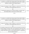
FIG. 1 is a flowchart of a control method of a washing machine according to an embodiment of the present disclosure. -
FIG. 2 is a flowchart of a control method of a washing machine according to another embodiment of the present disclosure. -
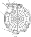
FIG. 3 is a schematic structural right view of a washing machine according to an embodiment of the present disclosure. -
FIG. 4 is a schematic structural rear view of a washing machine according to an embodiment of the present disclosure. -
FIG. 5 is a composition block diagram of a control device of a washing machine according to an embodiment of the present disclosure. -
FIG. 6 is a composition block diagram of a first washing machine according to an embodiment of the present disclosure. -
FIG. 7 is a composition block diagram of a second washing machine according to an embodiment of the present disclosure. -
FIG. 8 is a partial schematic structural view of a washing machine according to an embodiment of the present disclosure. - Description of Reference Numerals:
1-control device, 11-first processor, 12-first computer readable storage medium, 2-washing machine, 5-inner tub, 6-outer tub, 7-heating device, 8-connection structure, 81-air outlet, 82-water inlet, 83-water outlet, 9-drying system, 91-drying channel, 92-drying fan, 10-water inlet pipeline. - Embodiments of the present disclosure will be described below with reference to the accompanying drawings. It should be noted that, the embodiments in the present disclosure and the features in the embodiments may be combined arbitrarily without mutual contradiction.
- Embodiments of the present disclosure provide a control method of a washing machine. The washing machine may include an inner tub, a heating device, and an outer tub arranged outside the inner tub. The heating device is configured to heat water entering the outer tub.
- As illustrated in
FIG. 1 , the method may include operations at blocks S101 to S103. - At block S101, in response to a predetermined steam program being started, water is fed into the outer tub, and the inner tub of the washing machine is controlled to rotate at a first rotational speed r1.
- At block S102, the feeding of water is stopped in response to a water feeding level in the outer tub reaching a first predetermined water level.
- At block S103, the heating device is controlled to perform heating to generate steam, and clothes in the inner tub are treated with the steam.
- In an exemplary embodiment of the present disclosure, as illustrated in
FIG. 3 andFIG. 4 , the washing machine may include aheating device 7, aninner tub 5, and anouter tub 6 arranged outside theinner tub 5. Theheating device 7 is configured to heat water entering theouter tub 6 to generate steam. Theheating device 7 may be located between theinner tub 5 and theouter tub 6. For example, theheating device 7 is disposed between a bottom of the inner tub and a bottom of the outer tub. The inner tub may have one or more through holes. The through hole is configured to provide a passage for allowing the steam generated between theinner tub 5 and theouter tub 6 to enter theinner tub 5. Theouter tub 6 may be connected to a water inlet port to feed water into the outer tub through the water inlet port. - A steam generator may be used for steam washing by the washing machine. However, the use of the steam generator results in high costs. Moreover, the steam generator has disadvantages such as poor manufacturing and poor reliability. In addition, user's using effect is not significant.
- In an exemplary embodiment of the present disclosure, with the above washing machine structure, a simple, feasible, and reliable steam generation structure can be realized, thereby reducing manufacturing costs.
- In an exemplary embodiment of the present disclosure, after the washing machine starts the steam program, water needs to be first fed into the outer tub before the steam is generated. During the feeding of water, the inner tub may be controlled to rotate synchronously. At this time, a rotational speed of the inner tub may be the first rotational speed r1.
- In an exemplary embodiment of the present disclosure, the first rotational speed r1 during the feeding of water may be a high rotational speed. In this way, water can be thrown off due to rotation of the inner tub at the high rotational speed even if water falls onto an outer wall of the inner tub during the feeding of water. As a result, it is possible to prevent water flow from smoothly entering the inner tub through the through hole to wet the clothes inside the inner tub.
- Since once the clothes becomes wet, the clothes becomes heavier and would aggregate together, leaving no gaps between the clothes. Consequently, when the steam is generated later, even a substantial amount of the steam flowing into the inner tub, compact aggregation of the clothes is unfavorable for absorption of the steam. In addition, once the clothes are wetted, the clothes have already absorbed a significant amount of water, even be saturated in a case of excessive feeding of the water into the inner tub. In this way, the clothes would no longer absorb the steam. Further, since the clothes are wetted by a large amount of cold water, a temperature of the clothes is lowered, which is unfavorable for sterilization and wrinkle removal of the clothes. Moreover, once the steam is generated, the cold water absorbed by the clothes would also lower a temperature of the steam, even causing a large amount of the steam to be condensed into water, thereby significantly reducing steam effect.
- In an exemplary embodiment of the present disclosure, by controlling the inner tub to rotate at the high rotational speed during the feeding of water, the water flow can be effectively prevented from entering the inner tub, thus avoiding the wetting of the clothes by the water flow. Moreover, many problems potentially occurring as described in the above analysis can be also avoided. Therefore, with the solution according to the embodiments of the present disclosure, the problem in the steam washing can be solved by simply increasing the rotational speed of the inner tub during the feeding of water.
- In an exemplary embodiment of the present disclosure, a specific value of the first rotational speed r1 may be defined based on different types of washing machines, different capacities, different motor configurations, and different requirements, and the present disclosure is not limited in this regard.
- In an exemplary embodiment of the present disclosure, a water level detection device may be provided in the outer tub. A water level in the outer tub may be detected in real time by the water level detection device during the feeding of water.
- In an exemplary embodiment of the present disclosure, the water level detection device may be any existing water level detection device that can be implemented. A specific implementation manner of the water level detection device is not limited in the present disclosure.
- In an exemplary embodiment of the present disclosure, when the water level detection device detects that the water level in the outer tub has reached a predetermined water level such as the first predetermined water level, a corresponding water inlet valve may be controlled to be closed to stop the feeding of water into the outer tub.
- In an exemplary embodiment of the present disclosure, a height of the first predetermined water level is smaller than a vertical distance between a bottom of the inner tub and a bottom of the outer tub.
- In an exemplary embodiment of the present disclosure, in order to avoid the excessive feeding of water and direct flowing of water in the outer tub into the inner tub through the through hole located at the bottom of the inner tub, a vertical distance d between the bottom of the inner tub and the bottom of the outer tub may be used as a water level threshold, or 2d/3-3d/4 may be used as the water level threshold to provide an allowance.
- In an exemplary embodiment of the present disclosure, the heating device may be controlled to be switched on after the feeding of water is stopped or at a predetermined time before the feeding of water is stopped, to heat water in the outer tub to gradually generate the steam.
- In an exemplary embodiment of the present disclosure, the heating device may be a heating pipe, a heating plate, or the like. A specific implementation form, an arrangement position, an arrangement quantity, model selection, or heating power of the heating device are not limited herein and may be defined by the heating device itself as desired.
- In an exemplary embodiment of the present disclosure, the method further includes: controlling, during the heating of the heating device, the inner tub to rotate at a second rotational speed r2 to disperse the clothes in the inner tub to generate the steam. The second rotational speed r2 is smaller than the first rotational speed r1.
- As illustrated in
FIG. 2 , the method may include operations at blocks S201 to S203. - At block S201, in response to a predetermined steam program being started, water is fed into the outer tub, and the inner tub of the washing machine is controlled to rotate at the first rotational speed r1.
- At block S202, the feeding of water is stopped in response to the water feeding level in the outer tub reaching the first predetermined water level.
- At block S203, the heating device between the inner tub and the outer tub is controlled to perform the heating to generate the steam, and the inner tub of the washing machine is controlled to rotate at the second rotational speed r2 to disperse the clothes in the inner tub. The second rotational speed r2 may be smaller than the first rotational speed r1.
- In an exemplary embodiment of the present disclosure, after the heating device starts performing the heating, the inner tub may still be controlled to rotate at this time, and the rotational speed of the inner tub in this case may be a low rotational speed, for example, the second rotational speed r2 smaller than the first rotational speed r1. Since no more water is fed at this time, there is no concern about the fed water flow entering the inner tub to wet the clothes in the inner tub. In this case, rotating the inner tub at the low rotational speed is to allow the generated steam to enter the inner tub through the through hole better, thereby preventing the steam from being blocked outside the inner tub due to too fast rotational speed of the inner tub. In addition, through the rotation of the inner tub at the low rotational speed, it is possible to allow for gradual dispersion of the clothes in the inner tub, thereby increasing a contact area between the clothes and the air in the inner tub greater. In this way, greater exposure of the clothes to steam is facilitated, thus enhancing wrinkle removal effect.
- In an exemplary embodiment of the present disclosure, a specific value of the second rotational speed r2 may be defined based on different types of washing machines, different capacities, different motor configurations, and different requirements, and the present disclosure is not limited in this regard.
- In an exemplary embodiment of the present disclosure, during the generation of the steam, when rotating at a low rotational speed, the inner tub may rotate alternatively in a clockwise rotational direction and a counterclockwise rotational direction. During the alternate rotation, the inner tub may first rotate by one or more revolutions in the clockwise rotational direction, and then rotate by one or more revolutions in the counterclockwise rotational direction.
- In an exemplary embodiment of the present disclosure, the method may also include: detecting, from beginning of the heating to expiry of a predetermined steam generation duration (or a predetermined heating duration), whether the water level in the outer tub has dropped to a second predetermined water level in real time; continuing the heating to generate the steam when the water level in the outer tub has not yet reached the second predetermined water level; and feeding water into the outer tub again in response to the water level in the outer tub dropping to the second predetermined water level.
- In an exemplary embodiment of the present disclosure, when it is detected that the water level in the outer tub has dropped to the second predetermined water level, it is indicated that an amount of water in the outer tub is low. In order to prevent dry heating, water may be fed into the outer tub again. Moreover, the rotational speed of the inner tub is still increased during the feeding of water, allowing the inner tub to rotate at a high rotational speed during the feeding of water. After the feeding of water is completed, the rotational speed of the inner tub may be lowered again.
- In an exemplary embodiment of the present disclosure, the rotational speed of the inner tub may be increased to a third rotational speed when water is fed into the outer tub again. The third rotational speed may be greater than the second rotational speed.
- In an exemplary embodiment of the present disclosure, a specific value of the third rotational speed may be defined based on different types of washing machines, different capacities, different motor configurations, and different requirements, and the present disclosure is not limited in this regard.
- In an exemplary embodiment of the present disclosure, the third rotational speed may be set to be the same as, greater or smaller than the first rotational speed.
- In an exemplary embodiment of the present disclosure, when water is fed again, the water level of the outer tub is still limited by the first predetermined water level. The height of the first predetermined water level may still be smaller than the vertical distance d between the bottom of the inner tub and the bottom of the outer tub.
- In an exemplary embodiment of the present disclosure, as illustrated in
FIG. 3 ,FIG. 4 , andFIG. 8 , the washing machine may also include adrying system 9. A space between theinner tub 5 and theouter tub 6 of the washing machine may be in communication with thedrying system 9. - The method may also include: during the heating of the heating device to generate the steam, introducing the generated steam into the drying system to perform secondary heating on the introduced steam in the drying system.
- In an exemplary embodiment of the present disclosure, the
drying system 9 may be disposed at an upper part of theouter tub 6. The space between theinner tub 5 and theouter tub 6 may be in communication with thedrying system 9, allowing the generated steam to move upwards to enter thedrying system 9 through a communication channel. - In an exemplary embodiment of the present disclosure, as illustrated in
FIG. 3 ,FIG. 4 , andFIG. 8 , the washing machine may also include aconnection structure 8. Theconnection structure 8 may have anair outlet 81, awater inlet 82, and awater outlet 83. - The
drying system 9 may have a dryingchannel 91. Theinner tub 5 may be connected to the dryingchannel 91. - The
connection structure 8 is constructed to connect the space between theinner tub 5 and theouter tub 6 with the dryingchannel 91 of thedrying system 9 through thewater outlet 83 and theair outlet 81, be connected to awater inlet pipeline 10 for supplying water to the washing machine through thewater inlet 82, and be connected to theouter tub 6 of the washing machine through thewater outlet 83. That is, thewater inlet 82 of theconnection structure 8 is in communication with thewater inlet pipeline 10, thewater outlet 83 is in communication with theouter tub 6, and theair outlet 81 is in communication with the dryingchannel 91. - In an exemplary embodiment of the present disclosure, the
air outlet 81, thewater inlet 82, and thewater outlet 83 may be in communication with each other. Water is fed into theouter tub 6 through thewater inlet 82 and the water outlet 83 (a flow direction of the water is illustrated in a linear arrow ofFIG. 8 ). Steam rising to a top of theouter tub 6 enters the dryingchannel 91 through theair outlet 81 and the water outlet 83 (a flow direction of the steam is illustrated in a curve arrow ofFIG. 8 ). - In an exemplary embodiment of the present disclosure, after the steam enters the drying
channel 91, a hot drying program may be executed to heat the steam again. In order to prevent a strength of the tub (such as the inner tub 5) and airtightness of a drying channel sealing strip for sealing the drying channel from being affected by too high steam temperature, a drying temperature may be reasonably controlled and may not be too high. - In an exemplary embodiment of the present disclosure, as illustrated in
FIG. 8 , a dryingfan 92 may also be disposed in the dryingchannel 91. - In an exemplary embodiment of the present disclosure, in order to quickly introduce the steam into the drying
channel 91, the dryingfan 92 may be started. Moreover, a rotational speed of the dryingfan 92 may be reasonably controlled. - In an exemplary embodiment of the present disclosure, introducing the generated steam into the drying system to perform the secondary heating on the steam includes: starting the drying
fan 92 during the generation of the steam to allow the dryingfan 92 to suck the steam into the dryingchannel 91 through thewater outlet 83 and theair outlet 81 of theconnection structure 8 and heat the steam in the dryingchannel 91. In this way, the secondary heating of the steam is implemented. - In an exemplary embodiment of the present disclosure, the method may also include: blowing the secondary-heated steam into the inner tub through rotation of the drying
fan 9. - In an exemplary embodiment of the present disclosure, since the drying
channel 91 is in communication with theinner tub 5, by providing the dryingfan 92 with an appropriate rotational speed and rotational direction, the generated steam can be sucked into the dryingchannel 91 from theouter tub 6, and then the steam is delivered into theinner tub 5 after being subject the secondary heating in the dryingchannel 91. - In an exemplary embodiment of the present disclosure, a low-cost and double-steam effect can be achieved through the washing machine with the structure as described above.
- Therefore, when the washing machine runs the steam program, water is first fed into the outer tub, and the inner tub rotates during the feeding of water. At this time, the inner tub rotates at the rotational speed of r1. Once the water level reaches the first predetermined water level, the feeding of water is stopped. At this time, the heating device starts performing the heating to generate steam gradually. The inner tub also synchronously rotates to disperse the clothes. In this way, it is convenient to increasing the contact area of the clothes with the steam, thereby enhancing the wrinkle removal effect. At this time, the inner tub rotates at the rotational speed of r2. During the generation of the steam, the water level will drop. When the water level drops to a predetermined water level, water is fed again. In addition, r1 > r2 indicates that the rotational speed of the inner tub during the feeding of water is greater than the rotational speed of the inner tub during the generation of the steam. During the feeding of water, the rotational speed of the inner tub is high. Therefore, a large operation speed of the inner tub can be ensured, allowing for difficult flowing of the water into the inner tub.
- An embodiment of the present disclosure also provides a
control device 1 of a washing machine. As illustrated inFIG. 5 , thecontrol device 1 may include afirst processor 11 and a first computerreadable storage medium 12. The first computerreadable storage medium 12 has instructions stored thereon. When the instructions are executed by thefirst processor 11, the method according to any one of the above exemplary embodiments can be implemented. - In an exemplary embodiment of the present disclosure, any embodiment of the above control method may be applied in the embodiments of the
control device 1 of the washing machine, and the detailed description thereof will be omitted herein. - An embodiment of the present disclosure provides a
washing machine 2. As illustrated inFIG. 6 , thewashing machine 2 may include aninner tub 5, aheating device 7, anouter tub 6 arranged outside theinner tub 5, and thecontrol device 1 as described above. Theheating device 7 may be arranged between theinner tub 5 and theouter tub 6. Theheating device 7 is configured to heat water entering theouter tub 6 to generate steam. Theinner tub 5 has a through hole. The through hole is configured to provide a passage for allowing the stem to enter theinner tub 5. Theouter tub 6 is connected to a water inlet port. - In an exemplary embodiment of the present disclosure, any embodiment of the above control method of the washing machine may be applied in the embodiments of the
washing machine 2, and the detailed description thereof will be omitted herein. - In an exemplary embodiment of the present disclosure, as illustrated in
FIG. 7 andFIG. 8 , the washing machine also includes aconnection structure 8 and adrying system 9. - The
connection structure 8 may have anair outlet 81, awater inlet 82, and awater outlet 83. Thewater outlet 83 may be used as the water inlet port. - The
drying system 9 may have a dryingchannel 91 and a dryingfan 92 disposed in the dryingchannel 91. Theinner tub 5 is connected to the dryingchannel 91. - The
connection structure 8 is constructed to connect a space between theinner tub 5 and theouter tub 6 with the dryingchannel 91 through thewater outlet 83 and theair outlet 81, and be connected to thewater inlet pipeline 10 through thewater inlet 82 and to theouter tub 6 through thewater outlet 83. - The drying
fan 92 is configured to suck the steam into the dryingchannel 91 and blow the heated steam into theinner tub 5. - In an exemplary embodiment of the present disclosure, any one of the embodiments of the control method of the washing machine described above may be applied in the embodiments of the
washing machine 4, and detailed description thereof will be omitted herein. - It should be noted that, when the embodiments of the present disclosure relate to orientation indication such as up, down, left, right, front, and back, etc., the orientation indication is only used to explain a relative position relationship, a motion situation, etc. among components in a predetermined posture as shown in the drawings. When the specific posture is changed, the orientation indication is also changed accordingly.
- In addition, when the embodiments of the present disclosure relate to terms such as "first" and "second", the terms such as "first" and "second" are used herein only for purposes of description, rather than being understood as indicating or implying relative importance or implicitly specifying a number of the associated technical features. Therefore, the features associated with "first" and "second" may explicitly or implicitly include at least one of the features. In the description of the embodiments of the present disclosure, "plurality" means at least two, unless otherwise clearly and specifically defined.
- In the embodiments of the present disclosure, unless otherwise clearly specified and limited, terms such as "connect to", "fix" and the like should be understood in a broad sense. For example, the term "fix" may be a fixed connection or a detachable connection or connection as one piece; a mechanical connection or an electrical connection; a direct connection or an indirect connection through an intermediate; internal communication of two components or an interaction relationship between two components, unless otherwise clearly defined. For those of ordinary skill in the art, the specific meaning of the above-mentioned terms in the embodiments of the present disclosure may be understood according to specific circumstances.
- Those of ordinary skill in the art could understand that, all or some of the steps, systems, and functional modules/units of the apparatus in the method as disclosed above may be implemented as software, firmware, hardware, and appropriate combinations thereof. In a hardware implementation, the division between the functional modules/units mentioned in the above description does not necessarily correspond to the division of physical components. For example, one physical component may have a plurality of functions, or one function or one step may be performed cooperatively by several physical components. Some or all components may be implemented as software executed by a processor such as a digital signal processor or microprocessor, may be implemented as hardware, or may be implemented as an integrated circuit such as an application-specific integrated circuit. Such a software may be distributed on a computer readable medium. The computer readable medium may include a computer storage medium (or a non-transitory medium) and a communication medium (or a transitory medium). As is well known to those of ordinary skill in the art, the term "computer storage medium" includes volatile and non-volatile, removable and non-removable medium implemented in any method or technology for storing information, such as computer readable instructions, data structures, program modules, or other data. The computer storage medium may include, but is not limited to, RAM, ROM, EEPROM, flash memory or other memory technology, CD-ROM, digital versatile disks (DVD) or other optical disk storage, magnetic cassettes, magnetic tape, magnetic disk storage or other magnetic storage devices, or any other medium that may be used to store desired information and be accessed by a computer. In addition, it is well known to those of ordinary skill in the art that communication medium typically contains computer readable instructions, data structures, program modules, or other data in modulated data signals such as carriers or other transport mechanisms, and may include any information delivery medium. In addition, when describing a representative embodiment, the specification may have presented the method and/or process as a particular sequence of steps. However, the method or process should not be limited to steps in a particular order as described herein, without relying on the particular order of the steps described herein. As understood by those of ordinary skill in the art, other step sequences are possible. Therefore, the specific order of the steps set forth in the specification should not be construed as limiting the claims. In addition, the claims for this method and/or process should not be limited to the steps in which they are performed in the described order. Those skilled in the art may readily understand that these orders may be varied and remain within the spirit and scope of the embodiments of the present disclosure.
- Although the implementations disclosed herein are as described above, the described content is merely an implementation for easy understanding the present disclosure and is not used to limit the present disclosure. For those of ordinary skill in the art, any modification and change may be made in the form and details of implementation without departing from the spirit and scope disclosed herein. However, the patent scope of the present disclosure is still defined by the appended claims.
Claims (13)
- A control method of a washing machine, the washing machine comprising an inner tub, a heating device, and an outer tub arranged outside the inner tub, the heating device being configured to heat water entering the outer tub, the method comprising:in response to a predetermined steam program being started, feeding water into the outer tub, and controlling the inner tub of the washing machine to rotate at a first rotational speed r1;stopping the feeding of water in response to a water level in the outer tub rising to a first predetermined water level; andcontrolling the heating device to perform heating to generate steam, and treating clothes in the inner tub with the steam.
- The control method according to claim 1, further comprising:
controlling, during the heating of the heating device to generate the steam, the inner tub to rotate at a second rotational speed r2 to disperse the clothes in the inner tub. - The control method according to claim 2, wherein the second rotational speed r2 is smaller than the first rotational speed r1.
- The control method according to claim 2, further comprising:detecting, from beginning of the heating to expiry of a predetermined steam generation duration, whether the water level in the outer tub drops to a second predetermined water level; andfeeding water into the outer tub again in response to the water level in the outer tub dropping to the second predetermined water level, and increasing, in response to the feeding of water into the outer tub again, the rotational speed of the inner tub to a third rotational speed greater than the second rotational speed.
- The control method according to any one of claims 1 to 4, wherein a height of the first predetermined water level is smaller than a vertical distance between a bottom of the inner tub and a bottom of the outer tub.
- The control method according to any one of claims 1 to 4, wherein:the washing machine comprises a drying system in communication with a space between the inner tub and the outer tub; andthe method further comprises:
introducing, during the generation of the steam, the steam into the drying system to heat the steam by the drying system. - The control method according to claim 6, wherein:the washing machine further comprises a connection structure having an air outlet, a water inlet, and a water outlet;the drying system has a drying channel connected to the inner tub, a drying fan being disposed in the drying channel;the connection structure is constructed to connect the space between the inner tub and the outer tub with the drying channel through the water outlet and the air outlet, and be connected to a water inlet pipeline through the water inlet and to the outer tub through the water outlet; andsaid introducing the steam into the drying system to heat the steam by the drying system comprises:
starting the drying fan during the generation of the steam to allow the drying fan to suck the steam into the drying channel through the water outlet and the air outlet and heat the steam in the drying channel. - The control method according to claim 7, further comprising:
blowing the heated steam into the inner tub by the drying fan. - A control device of a washing machine, the control device comprising:a first processor; anda first computer readable storage medium having instructions stored thereon,wherein the instructions implement, when executed by the first processor, the method according to any one of claims 1 to 8.
- A washing machine, comprising:an inner tub having a through hole;an outer tub arranged outside the inner tub and connected to a water inlet port;a heating device configured to heat water entering the outer tub to generate steam, the through hole being configured to provide a passage for allowing the stem to enter the inner tub; andthe control device according to claim 9.
- The washing machine according to claim 10, wherein the heating device is disposed between the inner tub and the outer tub.
- The washing machine according to claim 10 or 11, further comprising:a connection structure having an air outlet, a water inlet, and a water outlet, the water outlet serving as the water inlet port; anda drying system having a drying channel connected to the inner tub, wherein:
the connection structure connects a space between the inner tub and the outer tub with the drying channel through the water outlet and the air outlet, and is connected to a water inlet pipeline through the water inlet and to the outer tub through the water outlet. - The washing machine according to claim 12, wherein the drying system further comprises a drying fan disposed in the drying channel, the drying fan being configured to suck the steam into the drying channel and blow the heated steam into the inner tub.
Applications Claiming Priority (2)
| Application Number | Priority Date | Filing Date | Title |
|---|---|---|---|
| CN202110446572.2A CN113174724B (en) | 2021-04-25 | 2021-04-25 | Washing machine and control method and device thereof |
| PCT/CN2021/130939 WO2022227505A1 (en) | 2021-04-25 | 2021-11-16 | Washing machine and control method and device thereof |
Publications (3)
| Publication Number | Publication Date |
|---|---|
| EP4328370A1 true EP4328370A1 (en) | 2024-02-28 |
| EP4328370A4 EP4328370A4 (en) | 2024-09-11 |
| EP4328370B1 EP4328370B1 (en) | 2026-05-06 |
Family
ID=76925101
Family Applications (1)
| Application Number | Title | Priority Date | Filing Date |
|---|---|---|---|
| EP21938965.7A Active EP4328370B1 (en) | 2021-04-25 | 2021-11-16 | Washing machine and control method and device thereof |
Country Status (3)
| Country | Link |
|---|---|
| EP (1) | EP4328370B1 (en) |
| CN (1) | CN113174724B (en) |
| WO (1) | WO2022227505A1 (en) |
Families Citing this family (5)
| Publication number | Priority date | Publication date | Assignee | Title |
|---|---|---|---|---|
| CN112981852B (en) * | 2021-02-04 | 2022-02-15 | 珠海格力电器股份有限公司 | Washing machine control method, washing machine control device and washing machine |
| CN113174724B (en) * | 2021-04-25 | 2023-04-18 | 无锡小天鹅电器有限公司 | Washing machine and control method and device thereof |
| CN116949752A (en) * | 2022-04-19 | 2023-10-27 | 青岛海尔洗涤电器有限公司 | Control method of washing machine and washing machine |
| CN115491859B (en) * | 2022-10-14 | 2025-08-26 | 珠海格力电器股份有限公司 | Control method, device, equipment and readable storage medium for clothing processing equipment |
| CN119777105B (en) * | 2024-12-26 | 2025-10-28 | 珠海格力电器股份有限公司 | Steam care method, control device and clothing treatment equipment |
Family Cites Families (10)
| Publication number | Priority date | Publication date | Assignee | Title |
|---|---|---|---|---|
| JP4030523B2 (en) * | 2004-05-12 | 2008-01-09 | 三洋電機株式会社 | Washing machine |
| EP1861540B1 (en) * | 2005-03-25 | 2015-10-28 | LG Electronics Inc. | Laundry machine |
| US8291731B2 (en) * | 2005-05-31 | 2012-10-23 | Lg Electronics Inc. | Washing machine generating and using the steam |
| CN106968080A (en) * | 2016-01-14 | 2017-07-21 | 青岛海尔滚筒洗衣机有限公司 | A kind of method that clothes washing is carried out using steam |
| EP3649284B1 (en) * | 2017-07-04 | 2021-12-08 | Electrolux Appliances Aktiebolag | Method to control operation of a washing machine |
| CN110409134A (en) * | 2018-04-28 | 2019-11-05 | 青岛海尔滚筒洗衣机有限公司 | Ultrasonic steam generator for laundry treatment equipment |
| CN112239933A (en) * | 2019-07-17 | 2021-01-19 | 青岛海尔滚筒洗衣机有限公司 | Method for refreshing dry clothes by using washing machine |
| CN112239935A (en) * | 2019-07-17 | 2021-01-19 | 青岛海尔洗衣机有限公司 | Method for removing wrinkles of dried clothes by washing and drying integrated machine |
| CN112160117A (en) * | 2020-09-15 | 2021-01-01 | 海信(山东)冰箱有限公司 | Control method of drum washing machine |
| CN113174724B (en) * | 2021-04-25 | 2023-04-18 | 无锡小天鹅电器有限公司 | Washing machine and control method and device thereof |
-
2021
- 2021-04-25 CN CN202110446572.2A patent/CN113174724B/en active Active
- 2021-11-16 WO PCT/CN2021/130939 patent/WO2022227505A1/en not_active Ceased
- 2021-11-16 EP EP21938965.7A patent/EP4328370B1/en active Active
Also Published As
| Publication number | Publication date |
|---|---|
| CN113174724A (en) | 2021-07-27 |
| WO2022227505A1 (en) | 2022-11-03 |
| CN113174724B (en) | 2023-04-18 |
| EP4328370B1 (en) | 2026-05-06 |
| EP4328370A4 (en) | 2024-09-11 |
Similar Documents
| Publication | Publication Date | Title |
|---|---|---|
| EP4328370B1 (en) | Washing machine and control method and device thereof | |
| CN105318493B (en) | The control method and device of humidifying air conditioner | |
| CN104903508B (en) | Clothes treatment device | |
| EP2386674A2 (en) | Washing machine having drying function and water filter thereof | |
| US20200071875A1 (en) | Clothes care apparatus and control method thereof | |
| US20210025108A1 (en) | Clothes care apparatus and control method thereof | |
| ES2396452T3 (en) | Machine for drying clothes comprising a reservoir of condensation water that feeds a cleaning device of a heat exchanger and a steam generator | |
| EP3112528B1 (en) | Dryer | |
| CN112074638A (en) | Laundry treating apparatus and control method thereof | |
| JP2010104579A (en) | Washing machine | |
| CN104066881A (en) | Appliance for drying laundry | |
| CN102374700A (en) | Dehumidifying-warming apparatus and clothes drier | |
| CN104132443A (en) | Drainage device and method and dehumidifier | |
| US20210017690A1 (en) | Clothes care apparatus and control method thereof | |
| JP2011229723A (en) | Drum washing machine | |
| JP6352614B2 (en) | Washing and drying machine | |
| JP5934617B2 (en) | Clothes dryer | |
| CN113338013A (en) | Control method and device of clothes dryer and clothes dryer | |
| JP2014033849A (en) | Clothing drying machine | |
| JP6334951B2 (en) | Clothes dryer | |
| KR102352396B1 (en) | Control Method for Laundry Treating Apparatus | |
| EP3301217A1 (en) | Method for determining the amount of water in a container for clothes dryer, process for drying clothes in a clothes dryer and clothes dryer implementing these method and process | |
| CN113186692B (en) | Washing machine and control device and method thereof | |
| JP2016052450A (en) | Washing and drying machine | |
| KR101387544B1 (en) | Cloth treating apparatus |
Legal Events
| Date | Code | Title | Description |
|---|---|---|---|
| STAA | Information on the status of an ep patent application or granted ep patent |
Free format text: STATUS: THE INTERNATIONAL PUBLICATION HAS BEEN MADE |
|
| PUAI | Public reference made under article 153(3) epc to a published international application that has entered the european phase |
Free format text: ORIGINAL CODE: 0009012 |
|
| STAA | Information on the status of an ep patent application or granted ep patent |
Free format text: STATUS: REQUEST FOR EXAMINATION WAS MADE |
|
| 17P | Request for examination filed |
Effective date: 20231122 |
|
| AK | Designated contracting states |
Kind code of ref document: A1 Designated state(s): AL AT BE BG CH CY CZ DE DK EE ES FI FR GB GR HR HU IE IS IT LI LT LU LV MC MK MT NL NO PL PT RO RS SE SI SK SM TR |
|
| DAV | Request for validation of the european patent (deleted) | ||
| DAX | Request for extension of the european patent (deleted) | ||
| REG | Reference to a national code |
Ref country code: DE Free format text: PREVIOUS MAIN CLASS: D06F0033520000 Ref country code: DE Ref legal event code: R079 Ref document number: 602021054140 Country of ref document: DE Free format text: PREVIOUS MAIN CLASS: D06F0033520000 Ipc: D06F0033340000 |
|
| A4 | Supplementary search report drawn up and despatched |
Effective date: 20240808 |
|
| RIC1 | Information provided on ipc code assigned before grant |
Ipc: D06F 35/00 20060101ALN20240802BHEP Ipc: D06F 105/48 20200101ALN20240802BHEP Ipc: D06F 105/02 20200101ALN20240802BHEP Ipc: D06F 103/18 20200101ALN20240802BHEP Ipc: D06F 25/00 20060101ALN20240802BHEP Ipc: D06F 39/40 20240101ALI20240802BHEP Ipc: D06F 33/36 20200101ALI20240802BHEP Ipc: D06F 33/34 20200101AFI20240802BHEP |
|
| GRAP | Despatch of communication of intention to grant a patent |
Free format text: ORIGINAL CODE: EPIDOSNIGR1 |
|
| STAA | Information on the status of an ep patent application or granted ep patent |
Free format text: STATUS: GRANT OF PATENT IS INTENDED |
|
| RIC1 | Information provided on ipc code assigned before grant |
Ipc: D06F 33/34 20200101AFI20260122BHEP Ipc: D06F 33/36 20200101ALI20260122BHEP Ipc: D06F 39/40 20240101ALI20260122BHEP Ipc: D06F 25/00 20060101ALN20260122BHEP Ipc: D06F 103/18 20200101ALN20260122BHEP Ipc: D06F 105/02 20200101ALN20260122BHEP Ipc: D06F 105/48 20200101ALN20260122BHEP Ipc: D06F 35/00 20060101ALN20260122BHEP |
|
| RIC1 | Information provided on ipc code assigned before grant |
Ipc: D06F 33/34 20200101AFI20260127BHEP Ipc: D06F 33/36 20200101ALI20260127BHEP Ipc: D06F 39/40 20240101ALI20260127BHEP Ipc: D06F 25/00 20060101ALN20260127BHEP Ipc: D06F 103/18 20200101ALN20260127BHEP Ipc: D06F 105/02 20200101ALN20260127BHEP Ipc: D06F 105/48 20200101ALN20260127BHEP Ipc: D06F 35/00 20060101ALN20260127BHEP |
|
| INTG | Intention to grant announced |
Effective date: 20260212 |
|
| GRAS | Grant fee paid |
Free format text: ORIGINAL CODE: EPIDOSNIGR3 |
|
| GRAA | (expected) grant |
Free format text: ORIGINAL CODE: 0009210 |
|
| STAA | Information on the status of an ep patent application or granted ep patent |
Free format text: STATUS: THE PATENT HAS BEEN GRANTED |
|
| AK | Designated contracting states |
Kind code of ref document: B1 Designated state(s): AL AT BE BG CH CY CZ DE DK EE ES FI FR GB GR HR HU IE IS IT LI LT LU LV MC MK MT NL NO PL PT RO RS SE SI SK SM TR |
|
| REG | Reference to a national code |
Ref country code: CH Ref legal event code: F10 Free format text: ST27 STATUS EVENT CODE: U-0-0-F10-F00 (AS PROVIDED BY THE NATIONAL OFFICE) Effective date: 20260506 Ref country code: GB Ref legal event code: FG4D |