EP4327711A1 - Dust collection pile, cleaning robot, and cleaning system - Google Patents
Dust collection pile, cleaning robot, and cleaning system Download PDFInfo
- Publication number
- EP4327711A1 EP4327711A1 EP21938748.7A EP21938748A EP4327711A1 EP 4327711 A1 EP4327711 A1 EP 4327711A1 EP 21938748 A EP21938748 A EP 21938748A EP 4327711 A1 EP4327711 A1 EP 4327711A1
- Authority
- EP
- European Patent Office
- Prior art keywords
- dust
- disposed
- dust collecting
- collecting pile
- barrel
- Prior art date
- Legal status (The legal status is an assumption and is not a legal conclusion. Google has not performed a legal analysis and makes no representation as to the accuracy of the status listed.)
- Pending
Links
Images











Classifications
-
- A—HUMAN NECESSITIES
- A47—FURNITURE; DOMESTIC ARTICLES OR APPLIANCES; COFFEE MILLS; SPICE MILLS; SUCTION CLEANERS IN GENERAL
- A47L—DOMESTIC WASHING OR CLEANING; SUCTION CLEANERS IN GENERAL
- A47L9/00—Details or accessories of suction cleaners, e.g. mechanical means for controlling the suction or for effecting pulsating action; Storing devices specially adapted to suction cleaners or parts thereof; Carrying-vehicles specially adapted for suction cleaners
- A47L9/10—Filters; Dust separators; Dust removal; Automatic exchange of filters
- A47L9/12—Dry filters
- A47L9/127—Dry filters tube- or sleeve-shaped
-
- A—HUMAN NECESSITIES
- A47—FURNITURE; DOMESTIC ARTICLES OR APPLIANCES; COFFEE MILLS; SPICE MILLS; SUCTION CLEANERS IN GENERAL
- A47L—DOMESTIC WASHING OR CLEANING; SUCTION CLEANERS IN GENERAL
- A47L11/00—Machines for cleaning floors, carpets, furniture, walls, or wall coverings
-
- A—HUMAN NECESSITIES
- A47—FURNITURE; DOMESTIC ARTICLES OR APPLIANCES; COFFEE MILLS; SPICE MILLS; SUCTION CLEANERS IN GENERAL
- A47L—DOMESTIC WASHING OR CLEANING; SUCTION CLEANERS IN GENERAL
- A47L11/00—Machines for cleaning floors, carpets, furniture, walls, or wall coverings
- A47L11/40—Parts or details of machines not provided for in groups A47L11/02 - A47L11/38, or not restricted to one of these groups, e.g. handles, arrangements of switches, skirts, buffers, levers
- A47L11/4091—Storing or parking devices, arrangements therefor; Means allowing transport of the machine when it is not being used
-
- A—HUMAN NECESSITIES
- A47—FURNITURE; DOMESTIC ARTICLES OR APPLIANCES; COFFEE MILLS; SPICE MILLS; SUCTION CLEANERS IN GENERAL
- A47L—DOMESTIC WASHING OR CLEANING; SUCTION CLEANERS IN GENERAL
- A47L11/00—Machines for cleaning floors, carpets, furniture, walls, or wall coverings
- A47L11/40—Parts or details of machines not provided for in groups A47L11/02 - A47L11/38, or not restricted to one of these groups, e.g. handles, arrangements of switches, skirts, buffers, levers
- A47L11/4013—Contaminants collecting devices, i.e. hoppers, tanks or the like
-
- A—HUMAN NECESSITIES
- A47—FURNITURE; DOMESTIC ARTICLES OR APPLIANCES; COFFEE MILLS; SPICE MILLS; SUCTION CLEANERS IN GENERAL
- A47L—DOMESTIC WASHING OR CLEANING; SUCTION CLEANERS IN GENERAL
- A47L9/00—Details or accessories of suction cleaners, e.g. mechanical means for controlling the suction or for effecting pulsating action; Storing devices specially adapted to suction cleaners or parts thereof; Carrying-vehicles specially adapted for suction cleaners
- A47L9/10—Filters; Dust separators; Dust removal; Automatic exchange of filters
- A47L9/16—Arrangement or disposition of cyclones or other devices with centrifugal action
- A47L9/1616—Multiple arrangement thereof
- A47L9/1625—Multiple arrangement thereof for series flow
-
- A—HUMAN NECESSITIES
- A47—FURNITURE; DOMESTIC ARTICLES OR APPLIANCES; COFFEE MILLS; SPICE MILLS; SUCTION CLEANERS IN GENERAL
- A47L—DOMESTIC WASHING OR CLEANING; SUCTION CLEANERS IN GENERAL
- A47L9/00—Details or accessories of suction cleaners, e.g. mechanical means for controlling the suction or for effecting pulsating action; Storing devices specially adapted to suction cleaners or parts thereof; Carrying-vehicles specially adapted for suction cleaners
- A47L9/10—Filters; Dust separators; Dust removal; Automatic exchange of filters
- A47L9/16—Arrangement or disposition of cyclones or other devices with centrifugal action
- A47L9/1616—Multiple arrangement thereof
- A47L9/1641—Multiple arrangement thereof for parallel flow
-
- A—HUMAN NECESSITIES
- A47—FURNITURE; DOMESTIC ARTICLES OR APPLIANCES; COFFEE MILLS; SPICE MILLS; SUCTION CLEANERS IN GENERAL
- A47L—DOMESTIC WASHING OR CLEANING; SUCTION CLEANERS IN GENERAL
- A47L9/00—Details or accessories of suction cleaners, e.g. mechanical means for controlling the suction or for effecting pulsating action; Storing devices specially adapted to suction cleaners or parts thereof; Carrying-vehicles specially adapted for suction cleaners
- A47L9/10—Filters; Dust separators; Dust removal; Automatic exchange of filters
- A47L9/16—Arrangement or disposition of cyclones or other devices with centrifugal action
- A47L9/1683—Dust collecting chambers; Dust collecting receptacles
-
- A—HUMAN NECESSITIES
- A47—FURNITURE; DOMESTIC ARTICLES OR APPLIANCES; COFFEE MILLS; SPICE MILLS; SUCTION CLEANERS IN GENERAL
- A47L—DOMESTIC WASHING OR CLEANING; SUCTION CLEANERS IN GENERAL
- A47L9/00—Details or accessories of suction cleaners, e.g. mechanical means for controlling the suction or for effecting pulsating action; Storing devices specially adapted to suction cleaners or parts thereof; Carrying-vehicles specially adapted for suction cleaners
- A47L9/10—Filters; Dust separators; Dust removal; Automatic exchange of filters
- A47L9/16—Arrangement or disposition of cyclones or other devices with centrifugal action
- A47L9/1691—Mounting or coupling means for cyclonic chamber or dust receptacles
-
- A—HUMAN NECESSITIES
- A47—FURNITURE; DOMESTIC ARTICLES OR APPLIANCES; COFFEE MILLS; SPICE MILLS; SUCTION CLEANERS IN GENERAL
- A47L—DOMESTIC WASHING OR CLEANING; SUCTION CLEANERS IN GENERAL
- A47L2201/00—Robotic cleaning machines, i.e. with automatic control of the travelling movement or the cleaning operation
- A47L2201/02—Docking stations; Docking operations
-
- A—HUMAN NECESSITIES
- A47—FURNITURE; DOMESTIC ARTICLES OR APPLIANCES; COFFEE MILLS; SPICE MILLS; SUCTION CLEANERS IN GENERAL
- A47L—DOMESTIC WASHING OR CLEANING; SUCTION CLEANERS IN GENERAL
- A47L2201/00—Robotic cleaning machines, i.e. with automatic control of the travelling movement or the cleaning operation
- A47L2201/02—Docking stations; Docking operations
- A47L2201/024—Emptying dust or waste liquid containers
-
- A—HUMAN NECESSITIES
- A47—FURNITURE; DOMESTIC ARTICLES OR APPLIANCES; COFFEE MILLS; SPICE MILLS; SUCTION CLEANERS IN GENERAL
- A47L—DOMESTIC WASHING OR CLEANING; SUCTION CLEANERS IN GENERAL
- A47L2201/00—Robotic cleaning machines, i.e. with automatic control of the travelling movement or the cleaning operation
- A47L2201/02—Docking stations; Docking operations
- A47L2201/028—Refurbishing floor engaging tools, e.g. cleaning of beating brushes
-
- A—HUMAN NECESSITIES
- A47—FURNITURE; DOMESTIC ARTICLES OR APPLIANCES; COFFEE MILLS; SPICE MILLS; SUCTION CLEANERS IN GENERAL
- A47L—DOMESTIC WASHING OR CLEANING; SUCTION CLEANERS IN GENERAL
- A47L9/00—Details or accessories of suction cleaners, e.g. mechanical means for controlling the suction or for effecting pulsating action; Storing devices specially adapted to suction cleaners or parts thereof; Carrying-vehicles specially adapted for suction cleaners
- A47L9/02—Nozzles
- A47L9/04—Nozzles with driven brushes or agitators
- A47L9/0494—Height adjustment of dust-loosening tools
Definitions
- the present disclosure relates to the field of intelligent home technologies, and more particularly, to a dust collecting pile, a cleaning robot, and a cleaning system.
- a cleaning robot may collect dust from the floor into a dust box located inside itself during cleaning.
- the present disclosure provides a dust collecting pile, a cleaning robot, and a cleaning system, which are used for collecting dust within the cleaning robot.
- a dust collecting pile for collecting dust within a dust box of a cleaning robot includes:
- a body including a dust inlet channel having a dust inlet that is configured to be communicated with the dust box, so that the dust within the dust box can enter the dust inlet channel through the dust inlet;
- a dust barrel detachably disposed on the body, the dust barrel including a dust inlet end and an airflow outlet end, and the dust inlet end being communicated with the dust inlet channel; a cyclone separator disposed within the dust barrel, the cyclone separator including a primary separation cyclone and a secondary separation cyclone, and the primary separation cyclone having an axis disposed approximately parallel to that of the secondary separation cyclone; and a fan assembly disposed on the body, an air inlet of the fan assembly being communicated with the airflow outlet end.
- the axis of the primary separation cyclone is coincided with that of the secondary separation cyclone.
- the axis of the primary separation cyclone and the axis of the secondary separation cyclone are respectively disposed approximately parallel to the axle center of the fan assembly.
- the body includes:
- the mounting body is detachably disposed on the base.
- the dust collecting pile further includes: a first filtering assembly disposed above the fan assembly, the first filtering assembly including an air inlet end that is communicated with the airflow outlet end via a communication pipeline, and an air outlet end that is communicated with the air inlet.
- the first filtering assembly includes:
- the filtering member is of a bag structure.
- the first filtering assembly further includes: a dust containing member having an air inlet end and an air outlet end, the dust containing member being disposed within the filtering member.
- the body further includes:
- the dust barrel including the cyclone separator may include a dust bag transition device; and the dust barrel may be mounted with a dust bag through the dust bag transition device after the cyclone separator is removed.
- the fan assembly includes:
- the body further includes a liquid outlet hole
- the dust collecting pile further includes:
- a cleaning robot includes:
- the cleaning module includes a rolling brush cover that is communicated with the dust inlet of the dust collecting pile through a lifting mechanism.
- the cleaning module includes a rolling brush that rotates when the cleaning robot executes a cleaning instruction on the operating surface; and after the cleaning robot is connected to the dust collecting pile, when a fan assembly of the dust collecting pile starts, the rolling brush starts at the same time or with a certain delay, and a rotating direction of the rolling brush at this point is opposite to that of the rolling brush when it moves on the operating surface automatically.
- a dust collecting pile for collecting dust within a dust box of a cleaning robot includes:
- the second filtering assembly is provided with an opening that can evade an air inlet conduit and/or the communication pipeline.
- the second filtering assembly further includes an air outlet surface
- the dust collecting pile further includes: an air outlet plate disposed above the second filtering assembly, the air outlet plate being provided with a through hole that is communicated with the air outlet surface.
- a dust collecting pile for collecting dust within a dust box of a cleaning robot includes:
- a dust collecting pile for collecting dust within a dust box of a cleaning robot includes:
- the wind pressure detection device is mounted on a circuit board of the dust collecting pile, thereby achieving the integration of an electronic device.
- the wind pressure measuring hole is formed between the fan assembly and the first filtering assembly.
- the outer side of the air inlet of the fan assembly is provided with a frustum-shaped protrusion, and the wind pressure measuring hole is formed at the frustum-shaped protrusion.
- a dust collecting pile for collecting dust within a dust box of a cleaning robot includes:
- a dust collecting pile for collecting dust within a dust box of a cleaning robot includes:
- a detachable sealing end cover is connected to one end of the separation filter screen, and a positioning block that matches the positioning and buckling device is disposed on the sealing end cover.
- a cleaning system includes the above-mentioned dust collecting pile and cleaning robot.
- the dust collecting pile in this embodiment can suck the dust within the dust box into the dust barrel for collection through the running of the fan assembly, and finally, airflows are discharged from the fan assembly, so as to enable recycling of the dust within the dust box of the cleaning robot into the dust barrel, so that automated processing may be enabled for the whole dust cleaning process.
- the axes of the primary separation cyclone and the secondary separation cyclone are designed to be approximately parallel, which reduces the complexity of the wind path in the dust barrel, thereby reducing the risk of dust accumulation when the dust that has been collected within the dust barrel increases, and enhancing the overall dust collecting effect of the cyclone separator.
- the dust barrel of the dust collecting pile may be a cyclone barrel without consumables, or a dust bag barrel with consumables facilitating users to collect garbage.
- Alternative dust barrel schemes meet the diversified usage requirements of the users.
- the cleaning robot and the dust collecting pile are well sealed, thereby improving the dust collecting effect of the dust collecting pile.
- the dust in the dust box of the cleaning robot may be better exported, thereby further strengthening the dust collecting effect of the dust collecting pile.
- references to "the/said” object or “an” object are also intended to represent one of a plurality of such possible objects.
- connection may be fixed connection, or detachable connection or integrated connection; or may be electric connection or signal connection; or may be direct connection; or indirect connection via an intermediation.
- connection may be fixed connection, or detachable connection or integrated connection; or may be electric connection or signal connection; or may be direct connection; or indirect connection via an intermediation.
- orientation words described in the exemplary embodiments of the present disclosure such as “upper”, “lower”, “inner”, and “outer” are described from view angles as shown in the drawings, and should not be construed as a limitation to the exemplary embodiments of the present disclosure.
- the element may be not only directly connected “onto”, “under”, “inside” or “outside” other elements (one or more), but also indirectly connected “onto”, “under”, “inside” or “outside” other elements (one or more) via an intermediate element.
- a cleaning system includes a dust collecting pile 2 and a cleaning robot 1.
- the cleaning robot includes a robot body.
- the robot body may have an approximately circular shape, or may also have other shapes, including but not limited to an approximate D shape for which the front is square and the rear is circular.
- the cleaning robot may further include a cleaning system, a perception system, a control system, a driving system, an energy system, a human-computer interaction system, etc.
- Various systems coordinate and cooperate with each other to enable the cleaning robot to move autonomously, thereby realizing a cleaning function.
- Functional elements and the like that constitute the respective systems described above in the cleaning robot may be integrated within the cleaning robot body.
- the cleaning robot body may include an upper closing cover, a chassis, and a middle frame disposed between the upper closing cover and the chassis.
- the middle frame may be used as a basic framework on which the respective functional elements are disposed.
- the upper closing cover and the chassis cover the surface of a device body, function to protect internal parts and components and may improve the aesthetics of the cleaning robot.
- the perception system is used for the cleaning robot to perceive an external environment such as terrain and a posture of the cleaning robot itself, and may provide various position information and motion state information about the robot to the control system of the cleaning robot.
- the perception system may include a position determining device including but not limited to an infrared transmitting and receiving device, a camera, and a laser distance sensor (LDS).
- the position determining device may be disposed at the top or on the side of the cleaning robot, and in the movement process of the cleaning robot, acquire a current position of the cleaning robot by determining a distance between the cleaning robot and a surrounding obstacle.
- a buffer is used to buffer a collision between the robot body and a surrounding object during movement.
- a layer of soft rubber is disposed on the surface of the buffer, and the buffer is spaced from the device body by a predetermined distance when mounted to the device body, so as to ensure that the device body can have enough time to decelerate in case of collision.
- the control system is disposed on a circuit main board within the robot body. It may be understood that the circuit main board is provided with various control circuits that control the running of the cleaning robot.
- the control system includes a non-transitory memory, a computing processor, etc.
- the computing processor may be a central processing unit, an application processor, etc., and draws a real-time map of an environment where the cleaning robot is located by using a positioning algorithm according to obstacle information fed back by the laser distance sensor.
- a current operating state of the cleaning robot is comprehensively determined, such as crossing a doorsill, getting on a carpet, locating at a cliff, being stuck from above or below, having a full dust box, being picked up, etc., and a specific next action strategy may also be given for different situations, so that the work of the cleaning robot better meets requirements, thereby improving the user experience.
- the human-computer interaction system may include a button on a host panel for a user to select functions, may further include a display screen and/or an indicator and/or a speaker for showing the user a current state of the robot or function selection options, and may further include a mobile phone client application.
- the cleaning robot may show the user a map of the environment where the robot is located, the position where the cleaning robot is located, the state information about the cleaning robot, etc. through the mobile phone client application.
- the energy system is used to provide electrical energy for the work of the functional elements of the respective systems, and mainly includes a charging battery and a power supply circuit.
- the charging battery may be a nickel-metal hydride battery and a lithium battery. When an electric quantity in the charging battery is lower than a predetermined minimum electric quantity, it may be charged by connecting a charging electrode disposed on the side of or below the device body with a charging device.
- the cleaning robot further includes a cleaning module, which is disposed on the robot body.
- the cleaning module removes debris from a surface to be cleaned by interfering with the surface to be cleaned.
- the cleaning module includes a wet cleaning portion and a dry cleaning portion.
- the wet cleaning portion may be a flat mop, which is connected onto the robot body.
- the dry cleaning portion may be a rolling brush 112, and sucks ground impurities into the dust box through a negative pressure generated by a fan with the cooperation of the rolling brush 112, the dust box, the fan, and the like. That is, the ground impurities enter the dust box through a garbage inlet of the robot body.
- the cleaning robot further includes a lifting structure connected to the cleaning module and configured to enable the cleaning module to move vertically relative to a mobile platform.
- the lifting structure not only may be connected to the dry cleaning portion separately to allow the dry cleaning portion to move vertically relative to the mobile platform, but also may be connected to the wet cleaning portion separately to allow the wet cleaning portion to move vertically relative to the mobile platform, and may be connected to the whole cleaning module including the dry cleaning portion and the wet cleaning portion simultaneously.
- the lifting structure may be equipped with an extra power device to allow the lifting structure to obtain a capability of active lifting or descending, such that the cleaning module can lift or descend actively relative to the mobile platform.
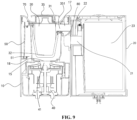
- the dust collecting pile includes a body 10, a dust barrel 20, and a fan assembly 40.
- the body 10 includes a dust inlet channel 11, where the dust inlet channel 11 has a dust inlet 111 which is used to be communicated with the dust box, so that dust within the dust box can enter the dust inlet channel 11 through the dust inlet 111.
- the dust barrel 20 is detachably disposed on the body 10, and a dust inlet end 21 of the dust barrel 20 is communicated with the dust inlet channel 11, so as to collect the dust entering from the dust inlet channel 11.
- the dust barrel 20 may be cylindrical and disposed on the body 10 vertically.
- the dust barrel includes a dust bag or a cyclone separator, where the body is selectively mounted with the dust barrel including the dust bag or the dust barrel including the cyclone separator.
- the fan assembly 40 is disposed on the body 10, where an air inlet 41 of the fan assembly 40 is communicated with an airflow outlet end 22 of the dust barrel 20, and the fan assembly 40 generates a negative pressure, so as to ensure that the dust within the dust box can enter the dust inlet channel 11 through the dust inlet 111 and allow airflows to circulate.
- the dust within the dust box includes the debris within the dust box.
- the fan assembly 40 and the dust barrel 20 have axes which are parallel with each other and perpendicular to a horizontal plane, and are both disposed on the body 10 side by side.
- Wind that enters an air inlet conduit through the dust inlet 111 and then enters the dust barrel 20 is discharged directly from the airflow outlet end 22 after cyclone separation, the airflows enter and exit horizontally, and air paths are simple and efficient, so that it is not easy to cause dust blockage.
- lower surfaces of the dust barrel 20 and the fan assembly 40 are generally on the same horizontal plane.
- the cleaning robot when the cleaning robot is triggered upon the completion of cleaning, insufficient electric quantity itself or full garbage in the dust box, the cleaning robot may move back to the dust collecting pile to complete charging or unload the garbage in the dust box into the dust collecting pile.
- the dust collecting pile includes a signal transmitting device, for example, the signal transmitting device transmits communication signals continuously within a certain angle range for the cleaning robot to be captured.
- the cleaning robot may determine the position of the dust collecting pile and move to the dust collecting pile by means of a navigation function.
- the position of the dust collecting pile may be recorded on a map.
- the cleaning robot preferentially goes to the position of the dust collecting pile that has been recorded on the map, determines the position of the dust collecting pile based on the signal transmitting device of the dust collecting pile and moves to the dust collecting pile through the navigation function, so as to reduce the time to look for the dust collecting pile and improve the efficiency of returning to the dust collecting pile.
- an outer side of the dust inlet 111 may be provided with a sealing ring
- an outer side of the rolling brush 112 of the robot is provided with a rolling brush cover 113
- the sealing ring corresponds to a part of the robot body and a part of the rolling brush cover 113.
- the lifting structure may allow the rolling brush 112 and the rolling brush cover 113 of the cleaning robot to move in an approximate vertical direction, so as to facilitate better sealing cooperation with the dust inlet 111 and the sealing ring.
- the dust collecting pile in this embodiment can suck the dust within the dust box into the dust barrel 20 for collection through the running of the fan assembly 40, and finally, the airflows are discharged from the fan assembly 40, such that the dust within the dust box of the cleaning robot can be recycled into the dust barrel 20. Therefore, automated processing may be enabled for the whole dust cleaning process.
- the rolling brush 112 of the robot may rotate counter to a cleaning direction in cooperation with the running of the fan assembly 40, thereby facilitating the fan assembly 40 to better discharge the dust in the dust box.
- the dust barrel 20 is detachably disposed on the body 10, so as to facilitate cleaning and replacing of the dust barrel 20.
- the dust barrel 20 includes a cyclone separator 24.
- the cyclone separator 24 may be one known in the related art.
- a working principle of the cyclone separator is as follows: when particles are used to perform a high-speed rotation in the airflows with the help of a rotary motion caused by tangential introduction of the airflows, and a centrifugal force is much greater than a gravity; since the greater the speed is, the greater the centrifugation and sedimentation speed obtained by the particles is, when the particles containing solid particles enter a cone-shaped cylinder in a tangential direction with gas and rotate in the cylinder, the airflows collide with a wall of the cyclone separator, and the particles hit a wall of a tube and descend in a rotary manner, thereby achieving the purpose of separation between the solid and the gas.
- the gas finally enters an air inlet end 31 of a first filtering assembly 30 through the airflow outlet end 22
- the cyclone separator 24 includes a primary separation cyclone 241 and a secondary separation cyclone 242.
- the primary separation cyclone 241 has an axis disposed approximately parallel to that of the secondary separation cyclone 242. After the axis of the primary separation cyclone 241 is disposed approximately parallel to the axis of the secondary separation cyclone 242, the complexity of a wind path in the dust barrel can be reduced greatly, thereby reducing the risk of dust accumulation when the dust that has been collected within the dust barrel increases, and enhancing the overall dust collecting effect of the cyclone separator.
- the axes of the primary separation cyclone 241 and the secondary separation cyclone 242 may be coincided completely to make the wind path in the dust barrel more unimpeded.
- the secondary separation cyclone 242 may include a plurality of cyclone separators, which are mainly in the shape of a cone with a large upper end and a small lower end and distributed around the axis of the secondary separation cyclone 242 respectively.
- the arrangement of a plurality of groups of cyclone separators improves the dust separation efficiency of the secondary separation cyclone, and further enhances the dust receiving capacity of the dust collecting pile.
- the number of the secondary cyclone separators may be nine, twelve, or fifteen, and the larger the number is, the higher the separation efficiency is.
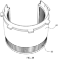
- a separation filter screen 243 is disposed in the periphery of the secondary separation cyclone 242.
- a primary cyclone is formed by an outer surface of the primary separation cyclone 241, an inner surface of the dust barrel 20, and an outer surface of the separation filter screen 243 together. Air separated by the primary cyclone separates larger particle garbage out of the airflows, which falls onto an outer side of the primary separation cyclone 241.
- the separation filter screen 243 is used for passage of the airflows that enter the secondary separation cyclone 242 after primary cyclone separation.
- the separation filter screen 243 is preferentially a metal filter screen, which may prolong the service life and improve the filtering effect.
- the separation filter screen 243 is an annular mesh, and a support frame of the primary separation cyclone 241 is used to settle a bottom of the separation filter screen 243.
- the particle garbage filtered out by the separation filter screen 243 is gathered under the support frame of the primary separation cyclone 241.
- An outer edge of the support frame of the primary separation cyclone 241 may extend downward to form a skirt shape to prevent the particle garbage separated by the primary cyclone from moving upward.
- the secondary separation cyclone 242 further includes a sealing end cover 246.
- the sealing end cover 246 is an annular plate distributed around an axis of the sealing end cover 246 in a rotary manner for sealing the airflows passing through the separation filter screen 243.
- a sealing space is formed by the separation filter screen 243, an inner wall of the primary separation cyclone 241, and the sealing end cover 246 to seal a secondary cyclone of the airflows passing through the separation filter screen 243.
- Each secondary separation cyclone 242 forms a gas-solid separation cyclone, and separated solid particle garbage falls into an inner side of the primary separation cyclone 241.
- the sealing end cover 246 and the bottom of the separation filter screen 243 may also not on the same horizontal plane according to practical situations.
- a positioning and buckling device is disposed between the secondary separation cyclone 242 and the separation filter screen 243.
- the positioning and buckling device includes a positioning and clamping block 244 and a positioning and clamping groove 245.
- the positioning and clamping block 244 and the separation filter screen 243 are disposed on the secondary separation cyclone 242 and the separation filter screen 243 respectively to achieve a position-limiting fit of the secondary separation cyclone 242 and the separation filter screen 243.
- the design of the positioning and buckling device ensures that the user may simply and conveniently mount the secondary separation cyclone 242 and the separation filter screen 243 again respectively after detaching and cleaning the secondary separation cyclone 242 and the separation filter screen 243 of the dust barrel, without incomplete sealing caused by loose buckling or improper mounting.
- the sealing end cover 246 is provided with a positioning block 247.
- the positioning block 247 is fitted with the positioning and buckling device, which can also ensure that the user may simply and conveniently mount the sealing end cover 246 again after detaching and cleaning the sealing end cover 246, without incomplete sealing caused by loose buckling or improper mounting.
- the body 10 includes a base 101 and a mounting body 102.
- the dust inlet channel 11 is formed within the base 101, the dust inlet 111 is formed in the top of the base 101, and the cleaning robot moves to the base 101 to clean the dust.
- the mounting body 102 is connected to the base 101, and an air inlet conduit 80 is provided within the mounting body 102. As shown in FIG. 8 , the air inlet conduit 80 communicates the dust inlet channel 11 with the dust inlet end 21, so that the dust enters the dust barrel 20 from the dust inlet channel 11 through the air inlet conduit 80.
- the dust barrel 20 is detachably disposed on the mounting body 102.
- the fan assembly 40 is disposed on the mounting body 102.
- the cleaning robot enters the base 101 from a front end of the base 101, and the mounting body 102 is disposed at a rear end of the base 101, so that the cleaning robot may not collide with the mounting body 102 during movement.
- the mounting body 102 and the base 101 may be of an integrated structure.
- the integrated structure may be integrated molding, or may also refer to connecting and fixing two separate components to form an integral structure.
- the mounting body 102 is detachably connected to the base 101. That is, the mounting body 102 may be separated from the base 101 before use, so as to facilitate transportation and storage, etc., and the mounting body 102 is connected to the base 101 by means of connection in the related art such as a fastener or engagement during use.
- the air inlet conduit 80 may be connected onto the base 101, that is, the air inlet conduit 80 is connected onto the base 101 after the mounting body 102 is separated from the base 101.
- the air inlet conduit 80 may be connected onto the mounting body 102, that is, the air inlet conduit 80 is connected onto the mounting body 102 after the mounting body 102 is separated from the base 101.
- the air inlet conduit 80 may be separated from the base 101 and the mounting body 102. In some embodiments, it is not excluded that the air inlet conduit 80 is integrated onto the base 101 or the mounting body 102.
- the dust collecting pile further includes the first filtering assembly 30.
- the first filtering assembly 30 is disposed above the fan assembly 40.
- the air inlet end 31 of the first filtering assembly 30 is communicated with the airflow outlet end 22 of the dust barrel 20, so as to filter the airflows discharged through the dust barrel 20.
- An air outlet end 32 of the first filtering assembly 30 is communicated with the air inlet 41 of the fan assembly 40.
- the fan assembly 40 runs and generates a negative pressure at this time, which can suck the dust within the dust box into the dust barrel 20 for collection, and the airflows are filtered through the first filtering assembly 30 before entering the fan assembly 40, thereby avoiding the dust from entering the interior of the fan assembly 40.
- the airflows are discharged from the fan assembly 40, such that the dust within the dust box of the cleaning robot is recycled into the dust barrel 20. Therefore, automated processing may be enabled for the whole dust cleaning process.
- the first filtering assembly 30 is located above the fan assembly 40. That is, the airflows discharged from the dust barrel 20 need to be filtered through the first filtering assembly 30 first, and then flow into the air inlet 41 of the fan assembly 40 from the bottom of the first filtering assembly 30, so that the distribution of a flowing path of the airflows is more reasonable, and it can be ensured that the distribution of components is more reasonable, thereby utilizing a height space effectively.
- the first filtering assembly 30 may be directly disposed on the body 10, or may also be directly disposed on the fan assembly 40.
- the first filtering assembly 30 is disposed on the mounting body 102. That is, after the mounting body 102 is separated from the base 101, the dust barrel 20, the first filtering assembly 30, and the fan assembly 40 may be all separated from the base 101 along with the mounting body 102.
- the first filtering assembly 30 is detachably disposed on the mounting body 102, or may also be fixed onto the mounting body 102.
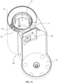
- the body 10 further includes: a first mounting portion 13 and a second mounting portion 14.
- the first mounting portion 13 and the second mounting portion 14 are respectively used to mount the dust barrel 20 and the first filtering assembly 30.
- the first mounting portion 13 and the second mounting portion 14 are disposed on the mounting body 102.
- a first detection member is disposed between the dust barrel 20 and the first mounting portion 13 and used for detecting whether the dust barrel 20 and the first mounting portion 13 are mounted in position. For example, when the dust barrel 20 and the first mounting portion 13 are mounted in position, the first detection member may send a first signal.
- a second detection member is disposed between the first filtering assembly 30 and the second mounting portion 14 and used for detecting whether the first filtering assembly 30 and the second mounting portion 14 are mounted in position. For example, when the first filtering assembly 30 and the second mounting portion 14 are mounted in position, the second detection member may send a second signal.
- the dust collecting pile further includes a control portion that is in signal connection with the first detection member or the second detection member.
- the control portion is in signal connection with the fan assembly 40, and the first detection member is in signal connection with the second detection member, so that the control portion cannot start the fan assembly 40 when at least one of the dust barrel 20 or the first filtering assembly 30 is not mounted in position. That is, the first detection member and the second detection member are in a series relationship. Therefore, the control portion can start the fan assembly 40 only when the first detection member sends the first signal and the second detection member sends the second signal.
- the first detection member may be connected to a control end of the second detection member, while a signal transmitting end of the second detection member is connected to the control portion. If the control end of the second detection member cannot receive the first signal sent by the first detection member, the second detection member cannot send a starting signal (for example, the second signal) to the control portion even if the first filtering assembly 30 and the second mounting portion 14 are mounted in position.
- in-position detection of the dust barrel 20 and in-position detection of the first filtering assembly 30 with an OR relationship can be implemented by connecting the first detection member with the second detection member in series. That is, if the dust barrel 20 is not in position, or the first filtering assembly 30 is not in position, or both of them are not in position, the control portion may recognize them as being not in position (that is, the control portion determines that the dust collecting pile is not mounted in position), so that electrical connection components and recognition components may be reduced.
- the dust barrel 20 is detachably connected to the first mounting portion 13, so as to facilitate the cleaning and replacing of the dust barrel 20.
- the dust barrel 20 and the first mounting portion 13 may be engaged, for example, through a fit between a bump and a slide way, or a mounting groove may be formed in the first mounting portion 13, while at least a part of the dust barrel 20 is located within the mounting groove, which is not defined here and may be selected according to actual needs as long as it is ensured that they are easy to mount and will not fall off arbitrarily.
- the first filtering assembly 30 is detachably connected to the second mounting portion 14, so as to facilitate the cleaning and replacing of the first filtering assembly 30, thereby improving the filtering capability of the first filtering assembly 30.
- first filtering assembly 30 and the second mounting portion 14 may be engaged, for example, through a fit between a bump and a slide way, or a mounting groove may be formed in the second mounting portion 14, while at least a part of the first filtering assembly 30 is located within the mounting groove, which is not defined here and may be selected according to actual needs as long as it is ensured that they are easy to mount and will not fall off arbitrarily.
- the second mounting portion 14 has a mounting cavity, while the first filtering assembly 30 is located within the mounting cavity.
- a sealed connection is formed between the upper portion of the first filtering assembly 30 and the body 10, while a second channel 18 is disposed on the body 10.
- the second channel 18 communicates the air outlet end 32 of the first filtering assembly 30 with the air inlet 41 of the fan assembly 40, so as to ensure that the airflows discharged through the first filtering assembly 30 only enter the air inlet 41 of the fan assembly 40 through the second channel 18.
- the dust barrel 20 includes a dust bag 23 or the cyclone separator 24.
- the dust barrel 20 may collect garbage through the dust bag 23 or through the cyclone separator 24.
- the dust bag may be a paper bag or cloth bag with good air permeable and dust proof effects, as long as it is easy to replace.
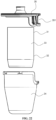
- the dust barrel 20 mounted with the cyclone separator 24 may be mounted with the dust bag 23 through a dust bag transition device 25 to meet different requirements of the user. That is, the dust bag transition device 25 is similar to a support and mainly used to mount the dust bag 23 onto the dust barrel 20 and has a specific structure similar to a component of the cyclone separator 24 that is connected to the dust barrel 20, which is not defined here as long as it can be connected to the dust barrel 20, actually like a component disposed by imitating a connection structure of the cyclone separator 24.
- the dust bag 23 may be provided with a transition portion 231 for being connected to the dust bag transition device 25, which is specifically as shown in FIG. 18 .
- the dust barrel 20 mounted with the cyclone separator 24 is provided with a handle 26 at the top and a starting button 27 at the bottom. Providing the handle 26 and the starting button 27 may allow the user to dump the garbage in the dust barrel 20 out by means of a lower opening.
- the dust barrel 20 mounted with the dust bag 23 is provided with a dust barrel top cover 28 at the top, so that the dust bag 23 may be removed from the top of the dust barrel 20.
- the first mounting portion 13 is selectively mounted with the dust barrel 20 including the dust bag or the dust barrel 20 including the cyclone separator. That is, an external structure of the dust barrel 20 may be of a general structure, a structure connected to the first mounting portion 13 may be a uniform structure, while the dust bag or the cyclone separator may be disposed inside the dust barrel 20, so that the first mounting portion 13 may be selectively mounted with the dust barrel 20 including the dust bag or the dust barrel 20 including the cyclone separator.
- the first mounting portion 13 and the second mounting portion 14 are spaced apart from each other, so that the dust barrel 20 or the first filtering assembly 30 can be mounted on the body 10 first, or the dust barrel 20 and the first filtering assembly 30 can be mounted on the body 10 simultaneously. That is, the dust barrel 20 and the first filtering assembly 30 are mounted without a limitation by a mounting sequence, and may be mounted and detached arbitrarily as required, without interference between the components, thereby simplifying the structures and facilitating the mounting.
- the first mounting portion 13 and the second mounting portion 14 may be distributed on two sides of the base 101 sequentially.
- two structures similar in appearance are formed above the base 101 after the dust barrel 20 is mounted to the first mounting portion 13, while the first filtering assembly 30 is mounted inside the second mounting portion 14.
- the first detection member is a contact detection element or a non-contact detection element
- the second detection member is a contact detection element or a non-contact detection element
- the first detection member may include a contact switch sensing element and a contact switch fitting element
- the second detection member may include a non-contact sensing element and a non-contact sensing and fitting element.
- the first mounting portion 13 is provided with a contact switch sensing element
- the dust barrel 20 is provided with a contact switch fitting element.
- the contact switch sensing element may be fitted with the contact switch fitting element when the dust barrel 20 is mounted to the first mounting portion 13, such that the contact switch sensing and fitting element can sense the contact switch sensing element.
- the second mounting portion 14 is provided with a non-contact sensing element
- the first filtering assembly 30 is provided with a non-contact sensing and fitting element.
- the non-contact sensing and fitting element may be fitted with the non-contact sensing element when the first filtering assembly 30 is mounted to the second mounting portion 14, such that the non-contact sensing and fitting element can sense the non-contact sensing element.
- the contact detection elements may be contact sensors in the related art, such as pressure sensors and switch elements
- the non-contact detection elements may be non-contact sensors in the related art, such as laser sensors and inductive proximity sensors.
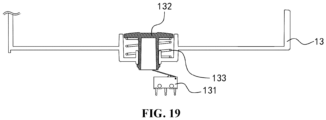
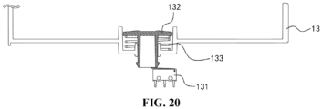
- the contact detection element includes: a switch 131 disposed on the first mounting portion 13; and a detection button 132 disposed to face the switch 131, so that the detection button 132 presses the switch 131 to be in a closed state when the dust barrel 20 and the first mounting portion 13 are mounted in position, that is, after the dust barrel 20 is mounted in position, the switch 131 is in a closed state, so as to output corresponding signals.
- the switch 131 may be a conventional button, which is connected onto a line, and the button can be turned on only when the detection button 132 presses in position, so as to achieve the conduction of the line, thereby enabling signal transmission.
- the detection button 132 may be disposed on the dust barrel 20.
- the contact detection element further includes: an elastic member 133, where the elastic member 133 is disposed on the first mounting portion 13, and the detection button 132 passes into the elastic member 133.
- the elastic member 133 is located between the detection button 132 and the first mounting portion 13, so that the elastic member 133 drives the detection button 132 to release the switch 131 when the dust barrel 20 is disengaged from the first mounting portion 13, so as to allow the switch 131 to be in an open state.
- the detection button 132 may be disposed on the first mounting portion 13 and moves downward depending on a pressure of the dust barrel 20. In addition, when the dust barrel 20 is disengaged from the first mounting portion 13 upward, the detection button 132 may move upward under the driving of the elastic member 133, so as to release the switch 131.
- the detection button 132 is provided with a position-limiting structure at the bottom end, thereby avoiding the detection button 132 from being disengaged from the first mounting portion 13.
- the switch 131 is disposed on the second mounting portion 14, and the detection button 132 is disposed to face the switch 131, so that the detection button 132 presses the switch 131 to be in the closed state when the first filtering assembly 30 and the second mounting portion 14 are mounted in position. That is, after the first filtering assembly 30 is mounted in position, the switch 131 is in the closed state, so as to output the corresponding signals.
- the detection button 132 may be disposed on the first filtering assembly 30.
- the detection button 132 is disposed on the second mounting portion 14, the elastic member 133 is disposed on the second mounting portion 14, and the detection button 132 passes into the elastic member 133.
- the elastic member 133 is located between the detection button 132 and the second mounting portion 14, so that the elastic member 133 drives the detection button 132 to release the switch 131 when the first filtering assembly 30 is disengaged from the second mounting portion 14, so as to allow the switch 131 to be in the open state.
- the elastic member 133 may be a spring.
- the dust barrel 20 may be provided with a sensing contact tab 29, where the sensing contact tab 29 may be separately disposed on the dust barrel 20 mounted with the cyclone separator 24 or the dust barrel 20 mounted with the dust bag 23, and the body 10 is provided with a sensing device fitted with the sensing contact tab 29.
- the sensing contact tab 29 is triggered: if the sensing contact tab 29 is separately disposed on the dust barrel 20 mounted with the cyclone separator 24, the dust barrel 20 mounted with the cyclone separator 24 is mounted onto the dust collecting pile when the sensing contact tab 29 is triggered, and the dust barrel 20 mounted with the dust bag 23 is mounted onto the dust collecting pile when the sensing contact tab 29 is not triggered; and if the sensing contact tab 29 is disposed on the dust barrel 20 mounted with the dust bag 23, the dust barrel 20 mounted with the dust bag 23 is mounted on the dust collecting pile when the sensing contact tab 29 is triggered, and the dust barrel 20 mounted with the cyclone separator 24 is mounted on the dust collecting pile when the sensing contact tab 29 is not triggered.
- the first filtering assembly 30 includes: a top cover 35 having an air inlet channel 351 that communicates the air inlet end 31 with a communication pipeline 17; and a filtering portion 34 disposed on the top cover 35 and disposed to face the air outlet end 32, such that the dust is filtered through the filtering portion 34, thereby avoiding the dust from entering the fan assembly 40.
- the filtering portion 34 may be of a filtering structure in the related art, such as a filter screen structure.
- a specific structure form for example, may be a circular network structure, thereby enabling the filtering of the dust.
- the filtering portion 34 is of a bag structure. That is, a filtering area of the filtering portion 34 increases, and a filtering contact area increases, so as to improve the filtering effect. Moreover, the service life of the filtering portion 34 may be greatly prolonged due to the increase in the filtering area, thereby reducing a replacing frequency of the filtering portion 34.
- the bag structure may be connected so that the filtering portion 34 has an accommodation space. The airflows enter the accommodation space and are then discharged from the filtering portion 34.
- the first filtering assembly 30 further includes: a dust containing member 33, where the dust containing member 33 has an air inlet end 31 and an air outlet end 32.
- the dust containing member 33 is disposed within the filtering portion 34, and the filtering portion 34 is disposed to face the air outlet end 32, so that the airflows discharged from the air outlet end 32 enter the air inlet 41 of the fan assembly 40 after passing through the filtering portion 34.
- the dust containing member 33 can absorb the dust within the airflows, thereby achieving primary absorption of the dust within the airflows, and avoiding a large amount of dust from entering the filtering portion 34 to block the filtering portion 34.
- the dust containing member 33 includes dust containing cotton. After entering the first filtering assembly 30, the airflows may pass through the dust containing cotton first.
- the dust containing cotton cannot intercept all the dust within specifications, but can intercept some of larger particles to reduce the risk that the filtering portion 34 is blocked, thereby prolonging the service life of the whole first filtering assembly 30.
- the dust containing member 33 includes sponge.
- the filtering portion 34 may be a filter, which may include filtering cotton.
- both the air inlet end 31 and the air outlet end 32 are located on an outer surface of the dust containing member 33, and an area of the air inlet end 31 is less than that of the air outlet end 32, so that the airflows can enter the dust containing member 33 from a relatively small surface to increase the length of a path that the airflows pass through the dust containing member 33, thereby increasing the absorption amount of the dust and further reducing the impact of the dust on the filtering portion 34.
- the filtering portion 34 encloses the dust containing member 33, so that the filtering portion 34 can not only implement the fixation of the dust containing member 33, but also allow the airflows flowing out of the dust containing portion 33 to be discharged directly through the filtering portion 34, thereby ensuring the filtering effect and simplify the structure.
- the dust containing member 33 and the filtering portion 34 are disposed on the top cover 35, so that the dust containing member 33 and the filtering portion 34 are fixed on the top cover 35.
- the top cover 35 of the first filtering assembly 30 may be connected to the body 10, so as to dispose the first filtering assembly 30 on the body 10.
- At least one of the dust containing member 33 or the filtering portion 34 may be directly fixed on the top cover 35, that is, the dust containing member 33 may be connected to the top cover 35, while the filtering portion 34 may enclose the dust containing member 33. That is, the filtering portion 34 is connected to the dust containing member 33, and may not be connected to the top cover 35 directly.
- the filtering portion 34 is connected to the top cover 35 to form an accommodation space between the filtering portion 34 and the top cover 35, and the dust containing member 33 is located within the accommodation space. That is, the dust containing member 33 is fixed within the accommodation spaced formed between the filtering portion 34 and the top cover 35.
- the filtering portion 34 is detachably disposed on the top cover 35, so as to facilitate replacing the filtering portion 34 and the dust containing member 33.
- the filtering portion 34 and the top cover 35 may be engaged, adhered or connected by a fastener, which is not defined here as long as they are easy to be detached and mounted.
- an area of the top cover 35 covering the dusting containing member 33 is less than that of the filtering portion 34 covering the dust containing member 33, so that the air inlet end 31 of the dust containing member 33 is smaller than the air outlet end 32, thereby ensuring that the airflows flow out rapidly, and the dust containing member 33 implements absorption of the dust to the maximum extent.
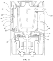
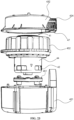
- the fan assembly 40 includes: a housing 43, a fan 44, and a flexible member 45.
- the housing 43 is disposed on the body 10, the flexible member 45 is located between the housing 43 and the fan 44, the fan 44 is fixed within the housing 43 by the flexible member 45, and the flexible member 45 avoids a direct contact between the fan 44 and the housing 43.
- the arrangement of the flexible member 45 may avoid the direct contact between the fan 44 and the housing 43, so as to avoid large noise.
- the housing 43 since the fan 44 is fixed within the housing 43 by the flexible member 45, the housing 43 may be enabled to adapt to the fans 44 of different types as long as the flexible member 45 is replaced, so as to improve the generality of the housing 43.
- a mounting cavity is formed in the body 10, both the fan assembly 40 and the first filtering assembly 30 are disposed within the mounting cavity, and a partition plate is disposed between the fan assembly 40 and the first filtering assembly 30.
- a second channel 18 is disposed on the partition plate. The second channel 18 communicates the air outlet end 32 of the first filtering assembly 30 with the air inlet 41 of the fan assembly 40, so as to ensure that the airflows discharged through the first filtering assembly 30 only enter the air inlet 41 of the fan assembly 40 through the second channel 18, which is specifically as shown in FIGs. 11 and 12 .
- the body 10 implements the protection of the fan assembly 40 and the first filtering assembly 30, and avoids the fan assembly 40 and the first filtering assembly 30 from being exposed to an external environment.
- the housing 43 includes: a first housing member 431; and a second housing member 432, where the second housing member 432 is detachably connected to the first housing member 431 to release or fix the fan 44 and the flexible member 45, which facilitates not only the mounting of the fan 44 and the flexible member 45 but also subsequent maintenance and replacement.
- the fans 44 of different types may be selected to replace the fan 44 of the original type, and only does the flexible member 45 need to be adaptively replaced, thereby achieving the generality of the housing 43.
- the second housing member 432 is connected to the first housing member 431 in a sealed manner, and the second housing member 432 may be connected to the first housing member 431 through a plurality of fasteners.
- the flexible member 45 includes: a first flexible portion 451 disposed between the fan 44 and the first housing member 431 to support the fan 44; and a second flexible portion 452, where at least a part of the second flexible portion 452 is disposed between the fan 44 and the second housing member 432 to clamp the fan 44 together with the first flexible portion 451.
- the second flexible portion 452 can be filled between the fan 44 and the second housing member 432, so as to avoid the fan 44 from moving relative to the second housing member 432 and ensure that the fan 44 is fixed within the second housing member 432.
- the first flexible portion 451 can be filled between the fan 44 and the first housing member 431, so as to avoid the fan 44 from moving relative to the first housing member 431 and ensure that the fan 44 is fixed within the first housing member 431.
- the first flexible portion 451 and the second flexible portion 452 implement the fixation of the fan 44 and completely avoid a hard contact between the fan 44 and the housing 43.
- the first flexible portion 451 may be connected to the second flexible portion 452.
- the first flexible portion 451 is disposed separately from the second flexible portion 452. That is, during specific mounting, the first flexible portion 451 and the fan 44 may be disposed within the first housing member 431 first, and then, the second flexible portion 452 and the second housing member 432 are fastened onto the fan 44 and the first housing member 431, and the second housing member 432 and the first housing member 431 are fixed, so as to complete the mounting of the fan assembly 40.
- a part of the second flexible portion 452 is clamped between the first housing member 431 and the second housing member 432 to seal a gap between the first housing member 431 and the second housing member 432, so as to prevent the first housing member 431 and the second housing member 432 from being sealed by using other sealing members, which is simple in structure and may reduce mounting steps.
- the first flexible portion 451 is a rubber mat
- the second flexible portion 452 is a rubber sleeve.
- the rubber mat is supported between the fan 44 and the first housing member 431, while the rubber sleeve is sleeved over an upper portion of the fan 44, so as to protect the fan 44.
- the second housing member 432 is provided with an airflow through hole 433, the airflow through hole 433 is communicated with the air inlet 41 of the fan 44, and there is a clearance between the first housing member 431 and the fan 44.
- An air discharging channel 46 is formed among the first flexible portion 451, the second flexible portion 452, the first housing member 431, and the fan 44, and the air discharging channel 46 is communicated with the air outlet 42 of the fan 44.
- the airflows discharged from the first filtering assembly 30 enter the air inlet 41 of the fan 44 through the airflow through hole 433, discharged into the air discharging channel 46 through the air outlet 42 of the fan 44, and finally discharged out from the air discharging channel 46, so as to achieve the circular flowing of the airflows.
- the first housing member 431 has a space 4311 accommodating the fan 44, and a plurality of wind holes 4312 is formed in a side wall of the space 4311. That is, the airflows within the air discharging channel 46 are discharged through the wind holes 4312, and the wind holes 4312 occupy a part of the first housing member 431 in a circumferential direction, so that the circular flowing of the airflows within the air discharging channel 46 may be achieved.
- the first housing member 431 has an inside housing member and an outside housing member which are sleeved with each other. An airflow space formed between the sleeved inside housing member and outside housing member is communicated with the air discharging channel 46 through the wind holes 4312, and finally the airflows are discharged from the fan assembly 40.
- the fan assembly 40 further includes an air discharging hole 434.
- the air discharging hole 434 is communicated with the air discharging channel 46, so as to discharge the airflows within the air discharging channel 46 out of the fan assembly 40.
- the air discharging hole 434 is formed in the housing 43, so as to discharge the airflows within the air discharging channel 46.
- the air discharging hole 434 may be formed in the first housing member 431, that is, the airflows within the air discharging channel 46 may be discharged from the fan assembly 40 without punching a hole in the second flexible portion 452.
- the air discharging hole 434 may also be formed in the second housing member 432, that is, a hole may be formed in the second flexible portion 452 to communicate the air discharging hole 434 with the air discharging channel 46. Specific positions of the air discharging hole 434 may not be defined, as long as it is ensured that the airflows can be discharged out of the air discharging channel 46.
- the fan assembly 40 further includes: a silencer 47, where the silencer 47 is disposed on the housing 43, where an inlet of the silencer 47 is communicated with the air discharging hole 434, or an outlet of the silencer 47 is communicated with the air discharging hole 434. Therefore, the airflows discharged out of the air discharging channel 46 are silenced through the silencer 47, so as to reduce noise caused by the airflows.
- the silencer 47 may be disposed inside the housing 43, the air discharging channel 46 is communicated with the inlet of the silencer 47, and the outlet of the silencer 47 is communicated with the air discharging hole 434, so that the airflows pass through the silencer 47 first and are then discharged out of the housing 43.
- the silencer 47 may be disposed outside the housing 43, the air discharging channel 46 is communicated with the air discharging hole 434, and the air discharging hole 434 is communicated with the inlet of the silencer 47, so that the airflows are discharged out of the housing 43 first, and then silenced by the silencer 47.
- the air discharging channel 46 is disposed around a circumferential outer surface of the fan 44, and the length of the air discharging channel 46 extending along the circumferential outer surface of the fan 44 is greater than that of the air discharging hole 434 extending along the circumferential outer surface of the fan 44. That is, the airflows discharged from the fan 44 are only discharged out of the housing 43 from a relatively fixed position, so that the airflows may rotate within the air discharging channel 46 for nearly one revolution, and are then discharged from the air discharging hole 434. As such, noise may be reduced by extending an airflow path.
- air outlets 42 may be formed on the circumferential outer surface of the fan 44 by nearly one revolution, and the air discharging channel 46 also forms a surrounding space for nearly one revolution at this point, so that airflows from the air outlets 42 at respective positions can be directly discharged into the air discharging channel 46, and at this point, the air discharging hole 434 on the housing 43 may be located in a circumferential direction of the housing 43.
- the air discharging hole 434 on the housing 43 may also be formed in the top of the housing 43, and at this point, the air discharging channel 46 may be communicated with the air discharging hole 434 through a pipeline, so as to ensure that the airflows discharged from the air discharging channel 46 need to be rotated to a relatively fixed position for discharge, thereby reducing noise by increasing the airflow paths.
- the body 10 is provided with a wind pressure measuring hole 48, a wind pressure pipeline 49 is connected to the wind pressure measuring hole 48, and an end of the wind pressure pipeline 49 is connected to a wind pressure detection device.
- the wind pressure detection device needs an electrical connection, in order to reduce the impact of a change in air pressure within the body 10 on the service life of electrical connection devices, the wind pressure detection device is mounted outside a wind path pipeline of the whole dust collecting pile. Therefore, it is necessary to connect the wind path pipeline with the wind pressure detection device together by the wind pressure measuring hole 48 and the wind pressure pipeline 49, so as to facilitate detecting the wind pressure within the wind path by the wind pressure detection device.
- the wind pressure detection device may be mounted on a circuit board of the dust collecting pile, thereby achieving the integration of an electronic device and facilitating the production of products.
- the wind pressure measuring hole 48 is formed between the fan assembly 40 and the first filtering assembly 30.
- the fan 44 may first draw air within the first filtering assembly 30 out to form a topical negative pressure after the fan 44 starts, and then form an airflow due to an air pressure, thereby completing the whole air-drawing action. Therefore, the highest measurement accuracy and measurement efficiency can be achieved by forming the wind pressure measuring hole 48 between the fan assembly 40 and the first filtering assembly 30.
- the first filtering assembly 30 is of a tubular structure and may be in direct contact with the wind pressure measuring hole 48 during mounting, a frustum-shaped protrusion is then disposed outside the air inlet of the fan assembly 40 and the wind pressure measuring hole 48 may be formed at the frustum-shaped protrusion, so as to avoid the wind pressure measuring hole 48 from being stuck by the first filtering assembly 30 to affect a measuring effect.
- the dust collecting pile further includes: a second filtering assembly 50, where the second filtering assembly 50 is disposed around the first filtering assembly 30, and an air collecting port 51 of the second filtering assembly 50 is communicated with the air outlet 42 of the fan assembly 40. That is, the airflows discharged from the air outlet 42 of the fan assembly 40 need to be filtered first through the second filtering assembly 50 and then discharged, thereby ensuring that the discharged airflows are clean.
- the second filtering assembly 50 may be of a conventional filtering structure, that is, may include a filter screen, so as to achieve secondary filtering of the airflows and ensure that the discharged airflows are clean.
- the second filtering assembly 50 may be of an annular structure, namely, a circumferential closed structure, so as to be disposed around the first filtering assembly 30. The airflows enter the fan assembly 40 from the first filtering assembly 30, that is, flow from top to bottom; and then, the airflows enter the second filtering assembly 50 from the fan assembly 40, that is, flow from bottom to top.
- the second filtering assembly 50 is provided with an opening 53, that is, the second filtering assembly 50 is of a circumferential non-closed structure.
- the dust collecting pile further includes an air inlet conduit 80.
- One end of the air inlet conduit 80 is communicated with the dust inlet channel 11, and the other end of the air inlet conduit 80 is communicated with the dust inlet end 21.
- the opening 53 can evade the air inlet conduit 80.
- the body 10 further includes a communication pipeline 17.
- Two ends of the communication pipeline 17 are respectively communicated with the air inlet end 31 of the first filtering assembly 30 and the airflow outlet end 22 of the dust barrel 20, and the opening 53 can evade the communication pipeline 17, so as to ensure the compactness of the structure.
- the body 10 is provided with a first channel 15.
- the first channel 15 communicates the air collecting port 51 of the second filtering assembly 50 with the air outlet 42 of the fan assembly 40.
- the body 10 is provided with a mounting groove 16, the second mounting portion 14 has an accommodation groove where the first filtering assembly 30 is mounted, the mounting groove 16 is disposed around the second mounting portion 14, and the second filtering assembly 50 is located within the mounting groove 16.
- the first channel 15 is communicated with the mounting groove 16, where the mounting groove 16 surrounds a part of the second mounting portion 14, and thus, may be adapted to the second filtering assembly 50 having the opening 53.
- a corresponding space within the opening 53 is used to form a space where the communication pipeline 17 and the air inlet conduit 80 are disposed.
- the second filtering assembly 50 includes a frame 54 and a filter screen 55, where the filter screen 55 is disposed on the frame 54, and an evasion groove 56 is formed in the filter screen 55.
- the evasion groove 56 includes a first opening 561, a second opening 562, and a third opening 563, where the first opening 561 and the second opening 562 are disposed to face each other, and two ends of the third opening 563 penetrate through the first opening 561 and the second opening 562.
- the frame 54 ensures the stability of the second filtering assembly 50.
- the frame 54 is disposed on the body 10, and the evasion groove 56 is configured to accommodate the second mounting portion 14 that accommodates the first filtering assembly 30, so that the airflows discharged from the fan assembly 40 enter between the second filtering assembly 50 and the second mounting portion 14.
- the evasion groove 56 includes the first opening 561, the second opening 562, and the third opening 563, where the first opening 561 and the second opening 562 are disposed to face each other, and two ends of the third opening 563 penetrate through the first opening 561 and the second opening 562. That is, the frame 54 is adapted to the filter screen 55, so that the opening 53 is formed in the second filtering assembly 50.
- the overall structure of the second filtering assembly 50 may be similar to a C-shaped structure or may be a U-shaped structure, which is not defined here and may be determined according to the specific structure form of the second mounting portion 14, so as to ensure the reasonable distribution of the components.
- the second filtering assembly 50 in this embodiment includes the frame 54 and the filter screen 55, and the evasion groove 56 is formed in the filter screen 55, so that the second filtering assembly 50 can be enabled to evade other internal structures, which can not only reduce the size of the filter screen 55, but also ensure reasonable arrangement of other components, thereby improving the usage performance of the second filtering assembly 50.
- the filter screen 55 is an arc-shaped filter screen. That is, on the premise of ensuring an effective filtering area, the structure of the filter screen 55 may be reduced to the maximum extent, so as to be adapted to a circumferential outer surface of the second mounting portion 14.
- an area of the third opening 563 is less than that of the filter screen 55, that is, it is ensured that the filter screen 55 has a sufficient filtering area.
- the frame 54 includes: a frame body 541 on which the filter screen 55 is disposed; and a sealing member 542, where the sealing member 542 is disposed inside the frame body 541, and a circumferential closed space is formed in the sealing member 542 to expose at least a part of the filter screen 55.
- the frame body 541 is configured to fix the filter screen 55, and the sealing member 542 may fit the second mounting portion 14 to ensure that there is no gap between the sealing member 542 and the second mounting portion 14, thereby ensuring that the airflows must be discharged out after being filtered through the filter screen 55.
- the sealing member 542 includes hepa paper.
- the frame body 541 includes: a first support 543 and a second support 544.
- the second support 544 is disposed to face the first support 543
- the filter screen 55 is connected between the second support 544 and the first support 543
- the sealing member 542 is disposed on an inner side of the second support 544 and the first support 543.
- the sealing member 542 may not only be used for sealing, but also implement the connection of the second support 544 and the first support 543.
- the frame body 541 further includes: a first connecting section 545 having two ends respectively connected to the first support 543 and the second support 544; and a second connecting section 546 having two ends respectively connected to the first support 543 and the second support 544.
- the first connecting section 545 is disposed to face the second connecting section 546; and the first support 543, the second support 544, the first connecting section 545, and the second connecting section 546 form a mounting space within which the filter screen 55 is located.
- the filter screen 55 includes a sealing foam.
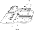
- the body 10 further includes a liquid outlet hole 12, where the liquid outlet hole 12 is formed in the base 101, and one end of the liquid outlet hole 12 is communicated with the dust inlet channel 11. Further, the liquid outlet hole 12 is located at the bottom of the body 10.
- the dust collecting pile further includes: a shielding member 90 movably disposed on the body 10, so that the shielding member 90 has a sealed position in which the liquid outlet hole 12 is shielded and an open position in which the liquid outlet hole 12 is released.
- the shielding member 90 When the dust in the dust box enters the dust inlet channel 11, the shielding member 90 is in the sealed position; and when the dust in the dust box stops entering the dust inlet channel 11, the shielding member 90 may move to the open position, so that the dust inlet channel 11 is communicated with the outside through the liquid outlet hole 12.
- the shielding member 90 closes the liquid outlet hole 12 to ensure that the dust inlet channel 11 is not communicated with the outside.
- the shielding member 90 may be opened, so that the dust inlet channel 11 is communicated with the outside. Liquid entering the dust inlet channel 11 may be discharged out of the dust inlet channel 11 through the liquid outlet hole 12, so as to ensure, to the maximum extent, that the dust inlet channel 11 is dry inside.
- the outside described above may be interpreted as an external environment space, or may also be other space independent from the dust inlet channel 11.
- a liquid collector may be provided to allow the liquid within the dust inlet channel 11 to flow into the liquid collector, and a space formed by the liquid collector may also be understood as the outside at this point.
- the shielding member 90 is movably disposed on the body 10, and may be driven by a driving mechanism to move, so as to achieve closing and releasing of the liquid outlet hole 12.
- the driving mechanism may be an air cylinder, an oil cylinder or an electric cylinder, and a telescopic rod of the driving mechanism may drive the shielding member 90 to move relative to the liquid outlet hole 12, thereby achieving the closing and releasing of the liquid outlet hole 12.
- the driving mechanism may include a motor, and the shielding member 90 is driven by the motor to rotate relative to the body 10, thereby achieving the closing and releasing of the liquid outlet hole 12.
- the fan assembly 40 starts to clean the dust within the dust box at the beginning of running, and the shielding member 90 can rotate from the open position to the sealed position.
- the control portion of the dust collecting pile may control the above driving mechanism to drive the shielding member 90 to move from the open position to the sealed position prior to controlling the fan assembly 40 to run, or the control portion may control the fan assembly 40 and the above driving mechanism to run simultaneously.
- the fan assembly 40 stops running the cleaning of the dust within the dust box is stopped, and the shielding member 90 can rotate from the sealed position to the open position.
- control portion of the dust collecting pile may control the above driving mechanism to drive the shielding member 90 to move from the sealed position to the open position after controlling the fan assembly 40 to stop running, or the control portion may control the above driving mechanism to run while controlling the fan assembly 40 to stop running.
- the shielding member 90 may be connected onto the body 10, and the movement of the shielding member 90 does not depend on the driving mechanism.
- the shielding member 90 can rotate from the open position to the sealed position under the driving of the fan assembly 40. That is, when the fan assembly 40 is running, depending on the negative pressure generated by the fan assembly 40, the shielding member 90 may be driven to move from the open position to the sealed position. In addition, when the fan assembly 40 stops running, the shielding member 90 can rotate from the sealed position to the open position under the action of gravity.
- the shielding member 90 may be disposed on a plate body, and this plate body is rotatably disposed on the body 10, so as to ensure that the shielding member 90 rotates from the sealed position to the open position under the action of gravity.
- the liquid outlet hole 12 is communicated with one side of the dust inlet channel 11 close to the dust barrel 20. That is, when the fan assembly 40 is running, the liquid may flow from the dust inlet 111 to the dust barrel 20 along the dust inlet channel 11. Therefore, after the fan assembly 40 stops running, most of the liquid is gathered at one side close to the dust barrel 20. At this point, the liquid can flow out conveniently from the liquid outlet hole 12 by opening the liquid outlet hole 12.
- the body 10 is provided with a sealing groove 19, and one end of the liquid outlet hole 12 is located within the sealing groove 19.
- the shielding member 90 When the shielding member 90 is in the sealed position, the shielding member 90 is located within the sealing groove 19, and the shielding member 90 implements sealing of the liquid outlet hole 12 reliably at this point.
- the shielding member 90 when the shielding member 90 is in the sealed position, the shielding member 90 may be in a clearance fit with a side wall of the sealing groove 19 and may stop against the liquid outlet hole 12 reliably, so as to achieve sealing of the liquid outlet hole 12.
- the shielding member 90 when the shielding member 90 is in the sealed position, the shielding member 90 may be in an interference fit with the side wall of the sealing groove 19. That is, the shielding member 90 seals the sealing groove 19, so as to enable the sealing of the liquid outlet hole 12.
- sealing groove 19 may be formed on one side of the liquid outlet hole 12 close to the dust inlet channel 11. That is, the sealing groove 19 is located within the dust inlet channel 11. At this point, the shielding member 90 may be driven by the driving mechanism to move.
- the sealing groove 19 may be disposed on one side of the liquid outlet hole 12 away from the dust inlet channel 11. That is, the sealing groove 19 is located outside the dust inlet channel 11.
- the shielding member 90 may be driven by the fan assembly 40 to move, and may be disengaged from the sealing groove 19 under the action of gravity.
- the shielding member 90 is disposed on a plate body.
- This plate body allows the shielding member 90 to be disengaged from the sealing groove 19 under the action of gravity when the fan assembly 40 does not work.
- the plate body may be driven to rotate only when the fan assembly 40 works, so that the shielding member 90 is located within the sealing groove 19, so as to achieve the sealing of the liquid outlet hole 12.
- the shielding member 90 is rotatably disposed on the body 10, so that the shielding member 90 can be switched between the sealed position and the open position.
- the shielding member 90 may be rotated by the driving mechanism relative to the body 10, so as to seal or release the liquid outlet hole 12.
- the shielding member 90 may be enabled to rotate under the action of the fan assembly 40, and may rotate from the sealed position to the open position under the action of gravity.
- the shielding member 90 is disposed on one side of the body 10 away from the dust inlet channel 11. That is, the shielding member 90 may rotate from the sealed position to the open position under the action of gravity.
- At least a part of the shielding member 90 is a flexible member, which not only has strong structure stability, but also can better implement the sealing of the liquid outlet hole 12.
- at least a part of the shielding member 90 is rubber, and the shielding member 90 may be a soft rubber sheet. After the fan assembly 40 runs and generates a negative pressure to suck up the soft rubber sheet, the liquid outlet hole 12 is blocked to achieve a sealing effect. When the fan assembly 40 does not work, the soft rubber sheet returns to its original position, and the liquid may flow out of the dust inlet channel 11 through the liquid outlet hole 12, so as to avoid the retention of a large amount of liquid within the dust inlet channel 11.
- the liquid outlet hole 12 may be a circular hole, a triangular hole or a rectangular hole.
- the liquid outlet hole 12 may also be an irregularly-shaped hole, which is not defined here.
- a specific structural shape of the sealing groove 19 for accommodating the shielding member 90 may also be circular, triangular or rectangular.
- the sealing groove 19 may also be an irregularly-shaped groove.
- a plurality of liquid outlet holes 12 is provided to increase a rate at which the liquid flows out and ensure that the liquid within the dust inlet channel 11 flows out reliably.
- At least one shielding member 90 is provided, where one shielding member 90 can shield a plurality of liquid outlet holes 12, so as to simplify the structure.
- a plurality of shielding members 90 is disposed in a one-to-one correspondence to the plurality of liquid outlet holes 12 to ensure that the respective shielding members 90 seal the respective liquid outlet holes 12 independently, thereby increasing the reliability of sealing.
- the dust collecting pile further includes: a spoiler 60, where the spoiler 60 is disposed around the second filtering assembly 50 to face an air outlet surface 52 of the second filtering assembly 50, thereby forming a spoiler channel 61.
- An air outlet channel 62 is formed between the spoiler 60 and the body 10, and a bottom end of the spoiler channel 61 is communicated with a bottom end of the air outlet channel 62. That is, airflows discharged from the air outlet surface 52 of the second filtering assembly 50 can flow downward under the blocking of the spoiler 60, and flow from the bottom of the spoiler channel 61 into the air outlet channel 62. Therefore, the airflow path may be increased, thereby achieving an effect of noise reduction.
- the spoiler 60 includes a first surface 63 and a second surface 64 that face each other, where the first surface 63 is disposed to face the air outlet surface 52 of the second filtering assembly 50 to form the spoiler channel 61, and the second surface 64 is disposed to face the body 10 to form the air outlet channel 62.
- the bottom end of the spoiler channel 61 is communicated with the bottom end of the air outlet channel 62, so that the airflows discharged from the air outlet surface 52 can enter the air outlet channel 62 from the bottom end of the spoiler channel 61, thereby increasing the airflow path.
- At least one of the body 10 or the second filtering assembly 50 is connected to the spoiler 60, for fixing the spoiler 60, thereby ensuring that the spoiler 60 stably implements airflow guidance.
- the upper side of the spoiler 60 is connected to at least one of the body 10 or the second filtering assembly 50 to avoid a top end of the spoiler channel 61 from being directly communicated with that of the air outlet channel 62, that is, to prevent the airflows from flowing from the top end of the spoiler channel 61 into the air outlet channel 62.
- the spoiler 60 may be connected onto the body 10, so that a sealed connection is formed between the top end of the spoiler 60 and the body 10.
- the top of the spoiler 60 is fixedly connected to the second filtering assembly 50. That is, the top of the spoiler 60 may be connected to a frame 54 of the second filtering assembly 50, so that a sealed connected is formed between the top end of the spoiler 60 and the second filtering assembly 50.
- the bottom end of the spoiler 60 is disposed in a suspended manner, so that the bottom end of the spoiler channel 61 is communicated with that of the air outlet channel 62. That is, both the second filtering assembly 50 and the body 10 may not be in contact with the bottom end of the spoiler 60, so that the airflows enter the air outlet channel 62 along the bottom end of the spoiler 60.
- the bottom end of the spoiler 60 may be lower than that of the air outlet surface 52, as long as it is ensured that a sealed connection is not formed between the bottom end of the spoiler 60 and the body 10.
- the bottom end of the spoiler 60 is higher than that of the air outlet surface 52. That is, a part of the airflows discharged from the air outlet surface 52 may not be stopped by the spoiler 60 as well.
- the spoiler 60 is provided with a communication channel 65.
- the spoiler channel 61 is also communicated with the air outlet channel 62 through the communication channel 65. That is, the communication channel 65 may allow some of the airflows to enter the air outlet channel 62, thereby preventing a large amount of airflows from directly impacting the spoiler 60. Therefore, the noise caused by airflow impacting may also be avoided on the basis of ensuring that flowing paths of some of the airflows are enlarged.
- the communication channel 65 is a through hole, which is located in a middle portion of the spoiler 60. That is, the spoiler channel 61 is also communicated with the air outlet channel 62 through the through hole.
- the communication channel 65 is a notch, which recesses upward from the bottom end of the spoiler 60. That is, it can be understood that an opening is formed in the spoiler 60 to release the airflows directly.
- a plurality of communication channels 65 is provided, so as to ensure that the airflows at different positions can enter the air outlet channel 62 directly through the communication channels 65.
- the air outlet surface 52 includes a curved surface
- the spoiler 60 includes an arc-shaped plate disposed to face the curved surface
- the plurality of communication channels 65 is disposed along a circumferential direction of the arc-shaped plate at intervals
- a shape of the spoiler 60 is adapted to the air outlet surface 52, which may not only ensure reliable filtering, but also enable the structure to have a reasonable layout.
- the dust collecting pile further includes: an air outlet plate 70, where the air outlet plate 70 is disposed above the second filtering assembly 50, the air outlet plate 70 is provided with a through hole 71, and the through hole 71 is communicated with the top end of the air outlet channel 62. That is, the airflows entering the air outlet channel 62 flow upward, and thus, are discharged through the through hole 71 in the air outlet plate 70. Under the action of the spoiler 60, the airflows may be formed from top to bottom, and then discharged from bottom to top, thereby achieving the purpose of noise reduction by lengthening the airflow path greatly.
- the through hole 71 of the air outlet plate 70 may be communicated with the air outlet surface 52 of the second filtering assembly 50 directly. That is, the spoiler 60 may be removed, and the airflows out of the air outlet surface 52 of the second filtering assembly 50 may be discharged through the through hole 71 of the air outlet plate 70 directly.
- the dust collecting pile further includes first charging contact tabs 103
- the cleaning robot 1 further includes second charging contact tabs.
- the first charging contact tabs 103 are electrically connected to the second charging contact tabs to allow the dust collecting pile to charge the cleaning robot.
- the first charging contact tabs 103 may be disposed on the body 10. Further, the first charging contact tabs 103 may be disposed on the base 101.
- the first charging contact tabs 103 are located on the same surface as the dust inlet 111, and the first charging contact tabs 103 and the dust inlet 111 are spaced from each other.
- both a plurality of first charging contact tabs 103 and a plurality of second charging contact tabs are disposed in pairs.
- the cleaning robot needs to move onto the body 10 for subsequent dust box cleaning or charging.
- the cleaning robot may move along the body 10, that is, the cleaning robot may perform a pile climbing motion.
- the pile climbing motion may be understood as follows: when a distance between the cleaning robot and the body 10 is less than a certain threshold, for example, when the cleaning robot has reached the vicinity of the body 10, the cleaning robot may move in a certain direction more obviously.
- a heading direction of the pile climbing motion may be understood as follows: in order to discharge the dust in the dust box into the dust inlet channel 11 or the second charging contact tabs to be in contact with the first charging contact tabs 103, the cleaning robot moves from a first position point to a second position point, and a direction from the first position point to the second position point is the heading direction of the pile climbing motion.
Landscapes
- Engineering & Computer Science (AREA)
- Mechanical Engineering (AREA)
- Filters For Electric Vacuum Cleaners (AREA)
- Placing Or Removing Of Piles Or Sheet Piles, Or Accessories Thereof (AREA)
- Cleaning In General (AREA)
Abstract
Description
- The present disclosure claims priority to
Chinese Patent Application No. 202110466452.9, filed on April 25, 2021 - The present disclosure relates to the field of intelligent home technologies, and more particularly, to a dust collecting pile, a cleaning robot, and a cleaning system.
- In the related art, a cleaning robot may collect dust from the floor into a dust box located inside itself during cleaning.
- After a certain period of use, it is necessary to open the cleaning robot to dump the dust within the dust box. This operation is extremely inconvenient, resulting in the failure of timely cleaning.
- However, in the existing dust collecting pile, a wind path has a relatively complex structure, which is prone to dust accumulation, making a dust collecting effect reduce over time; or users cannot choose consumables independently.
- The present disclosure provides a dust collecting pile, a cleaning robot, and a cleaning system, which are used for collecting dust within the cleaning robot.
- According to a first aspect of the present disclosure, a dust collecting pile for collecting dust within a dust box of a cleaning robot is provided. The dust collecting pile includes:
- a body including a dust inlet channel having a dust inlet that is configured to be communicated with the dust box, so that the dust within the dust box can enter the dust inlet channel through the dust inlet;
- a dust barrel detachably disposed on the body, the dust barrel including a dust inlet end and an airflow outlet end, and the dust inlet end being communicated with the dust inlet channel; a cyclone separator disposed within the dust barrel, the cyclone separator including a primary separation cyclone and a secondary separation cyclone, and the primary separation cyclone having an axis disposed approximately parallel to that of the secondary separation cyclone; and a fan assembly disposed on the body, an air inlet of the fan assembly being communicated with the airflow outlet end.
- In an embodiment of the present disclosure, the axis of the primary separation cyclone is coincided with that of the secondary separation cyclone.
- In an embodiment of the present disclosure, the axis of the primary separation cyclone and the axis of the secondary separation cyclone are respectively disposed approximately parallel to the axle center of the fan assembly.
- In an embodiment of the present disclosure, the body includes:
- a base, the dust inlet channel being disposed within the base; and
- a mounting body connected to the base, an air inlet conduit being disposed in the mounting body and communicating the dust inlet channel with the dust inlet end,
- where both the dust barrel and the fan assembly are disposed on the mounting body.
- In an embodiment of the present disclosure, the mounting body is detachably disposed on the base.
- In an embodiment of the present disclosure, the dust collecting pile further includes:
a first filtering assembly disposed above the fan assembly, the first filtering assembly including an air inlet end that is communicated with the airflow outlet end via a communication pipeline, and an air outlet end that is communicated with the air inlet. - In an embodiment of the present disclosure, the first filtering assembly includes:
- a top cover having an air inlet channel that communicates the air inlet end with the communication pipeline; and
- a filtering member disposed on the top cover and disposed to face the air outlet end.
- In an embodiment of the present disclosure, the filtering member is of a bag structure.
- In an embodiment of the present disclosure, the first filtering assembly further includes:
a dust containing member having an air inlet end and an air outlet end, the dust containing member being disposed within the filtering member. - In an embodiment of the present disclosure, the body further includes:
- a first mounting portion, a first detection member being disposed between the dust barrel and the first mounting portion and used for detecting whether the dust barrel and the first mounting portion are mounted in position; and
- a second mounting portion, a second detection member being disposed between the first filtering assembly and the second mounting portion and used for detecting whether the first filtering assembly and the second mounting portion are mounted in position, where
- the dust collecting pile further includes a control portion in signal connection with the first detection member or the second detection member, the control portion is in signal connection with the fan assembly, and the first detection member is in signal connection with the second detection member, so that the control portion cannot start the fan assembly when at least one of the dust barrel or the first filtering assembly is not mounted in position.
- In an embodiment of the present disclosure, the dust barrel including the cyclone separator may include a dust bag transition device; and the dust barrel may be mounted with a dust bag through the dust bag transition device after the cyclone separator is removed.
- In an embodiment of the present disclosure, the fan assembly includes:
- a housing disposed on the body;
- a fan; and
- a flexible member located between the housing and the fan, the fan being fixed within the housing by the flexible member, and the flexible member avoiding a direct contact between the fan and the housing.
- In an embodiment of the present disclosure, the body further includes a liquid outlet hole, and the dust collecting pile further includes:
- a shielding member movably disposed on the body, so that the shielding member has a sealed position in which the liquid outlet hole is shielded and an open position in which the liquid outlet hole is released, where
- when the dust of the dust box enters the dust inlet channel, the shielding member is in the sealed position, and when the dust of the dust box stops entering the dust inlet channel, the shielding member can move to the open position, so that the dust inlet channel is communicated with an outside through the liquid outlet hole.
- According to a second aspect of the present disclosure, a cleaning robot is provided. The cleaning robot includes:
- a mobile platform configured to move on an operating surface automatically;
- a cleaning module disposed on the mobile platform, the cleaning module including a dust box for receiving dust; and
- a lifting structure connected to the cleaning module and configured to enable the cleaning module to move vertically relative to the mobile platform, where
- the cleaning module is communicated with a dust inlet of a dust collecting pile when the cleaning robot is docked with the dust collecting pile.
- In an embodiment of the present disclosure, the cleaning module includes a rolling brush cover that is communicated with the dust inlet of the dust collecting pile through a lifting mechanism.
- In an embodiment of the present disclosure, the cleaning module includes a rolling brush that rotates when the cleaning robot executes a cleaning instruction on the operating surface; and
after the cleaning robot is connected to the dust collecting pile, when a fan assembly of the dust collecting pile starts, the rolling brush starts at the same time or with a certain delay, and a rotating direction of the rolling brush at this point is opposite to that of the rolling brush when it moves on the operating surface automatically. - According to a third aspect of the present disclosure, a dust collecting pile for collecting dust within a dust box of a cleaning robot is provided. The dust collecting pile includes:
- a body including a dust inlet channel having a dust inlet that is configured to be communicated with the dust box, so that the dust within the dust box can enter the dust inlet channel through the dust inlet;
- a dust barrel detachably disposed on the body, the dust barrel including a dust inlet end and an airflow outlet end, and the dust inlet end being communicated with the dust inlet channel;
- a fan assembly disposed on the body, an air inlet of the fan assembly being communicated with the airflow outlet end;
- a first filtering assembly disposed above the fan assembly, the first filtering assembly including an air inlet end that is communicated with the airflow outlet end via a communication pipeline, and an air outlet end that is communicated with the air inlet; and
- a second filtering assembly disposed around the first filtering assembly, the second filtering assembly including an air collecting port that is communicated with an air outlet of the fan assembly.
- In an embodiment of the present disclosure, the second filtering assembly is provided with an opening that can evade an air inlet conduit and/or the communication pipeline.
- In an embodiment of the present disclosure, the second filtering assembly further includes an air outlet surface, and the dust collecting pile further includes:
an air outlet plate disposed above the second filtering assembly, the air outlet plate being provided with a through hole that is communicated with the air outlet surface. - According to a fourth aspect of the present disclosure, a dust collecting pile for collecting dust within a dust box of a cleaning robot is provided. The dust collecting pile includes:
- a body including a dust inlet channel having a dust inlet that is configured to be communicated with the dust box, so that the dust within the dust box can enter the dust inlet channel through the dust inlet;
- a dust barrel detachably disposed on the body, the dust barrel including a dust inlet end and an airflow outlet end, and the dust inlet end being communicated with the dust inlet channel;
- a fan assembly disposed on the body, an air inlet of the fan assembly being communicated with the airflow outlet end;
- a second filtering assembly including an air collecting port that is communicated with an air outlet of the fan assembly, where
- the second filtering assembly includes a spoiler disposed around the second filtering assembly and disposed to face an air outlet surface of the second filtering assembly to form a spoiler channel.
- According to a fifth aspect of the present disclosure, a dust collecting pile for collecting dust within a dust box of a cleaning robot is provided. The dust collecting pile includes:
- a body including a dust inlet channel having a dust inlet that is configured to be communicated with the dust box, so that the dust within the dust box can enter the dust inlet channel through the dust inlet;
- a dust barrel detachably disposed on the body, the dust barrel including a dust inlet end and an airflow outlet end, and the dust inlet end being communicated with the dust inlet channel; and
- a fan assembly disposed on the body, an air inlet of the fan assembly being communicated with the airflow outlet end, where
- an outer side of the air inlet of the fan assembly is provided with a wind pressure measuring hole, a wind pressure pipeline is connected onto the wind pressure measuring hole, and a wind pressure detection device is connected to an end of the wind pressure pipeline.
- In an embodiment of the present disclosure, the wind pressure detection device is mounted on a circuit board of the dust collecting pile, thereby achieving the integration of an electronic device.
- In an embodiment of the present disclosure, the wind pressure measuring hole is formed between the fan assembly and the first filtering assembly.
- In an embodiment of the present disclosure, the outer side of the air inlet of the fan assembly is provided with a frustum-shaped protrusion, and the wind pressure measuring hole is formed at the frustum-shaped protrusion.
- According to a sixth aspect of the present disclosure, a dust collecting pile for collecting dust within a dust box of a cleaning robot is provided. The dust collecting pile includes:
- a body including a dust inlet channel having a dust inlet that is configured to be communicated with the dust box, so that the dust within the dust box can enter the dust inlet channel through the dust inlet;
- a dust barrel detachably disposed on the body, the dust barrel including a dust inlet end and an airflow outlet end, and the dust inlet end being communicated with the dust inlet channel; and
- a fan assembly disposed on the body, an air inlet of the fan assembly being communicated with the airflow outlet end, where
- the dust barrel includes a dust bag or a cyclone separator, where the body is selectively mounted with the dust barrel including the dust bag or the dust barrel including the cyclone separator.
- According to a seventh aspect of the present disclosure, a dust collecting pile for collecting dust within a dust box of a cleaning robot is provided. The dust collecting pile includes:
- a body including a dust inlet channel having a dust inlet that is configured to be communicated with the dust box, so that the dust within the dust box can enter the dust inlet channel through the dust inlet;
- a dust barrel detachably disposed on the body, the dust barrel including a dust inlet end and an airflow outlet end, and the dust inlet end being communicated with the dust inlet channel;
- a cyclone separator disposed within the dust barrel, the cyclone separator including a primary separation cyclone and a secondary separation cyclone, the primary separation cyclone having an axis disposed approximately parallel to that of the secondary separation cyclone;
- a separation filter screen disposed around an outer side of the secondary separation cyclone, and a positioning and buckling device being disposed between the secondary separation cyclone and the separation filter screen; and
- a fan assembly disposed on the body, an air inlet of the fan assembly being communicated with the airflow outlet end.
- In an embodiment of the present disclosure, a detachable sealing end cover is connected to one end of the separation filter screen, and a positioning block that matches the positioning and buckling device is disposed on the sealing end cover.
- According to an eighth aspect of the present disclosure, a cleaning system is provided. The cleaning system includes the above-mentioned dust collecting pile and cleaning robot.
- After the cleaning robot moves in position, the dust collecting pile in this embodiment can suck the dust within the dust box into the dust barrel for collection through the running of the fan assembly, and finally, airflows are discharged from the fan assembly, so as to enable recycling of the dust within the dust box of the cleaning robot into the dust barrel, so that automated processing may be enabled for the whole dust cleaning process. For the cyclone separator in the dust barrel in this embodiment, the axes of the primary separation cyclone and the secondary separation cyclone are designed to be approximately parallel, which reduces the complexity of the wind path in the dust barrel, thereby reducing the risk of dust accumulation when the dust that has been collected within the dust barrel increases, and enhancing the overall dust collecting effect of the cyclone separator.
- In addition, the dust barrel of the dust collecting pile may be a cyclone barrel without consumables, or a dust bag barrel with consumables facilitating users to collect garbage. Alternative dust barrel schemes meet the diversified usage requirements of the users.
- With the lifting device on the cleaning robot, the cleaning robot and the dust collecting pile are well sealed, thereby improving the dust collecting effect of the dust collecting pile. On the other hand, through a reverse rotation of the rolling brush, the dust in the dust box of the cleaning robot may be better exported, thereby further strengthening the dust collecting effect of the dust collecting pile.
- Various objects, features, and advantages of the present disclosure will become more apparent by considering the following detailed description of the preferred embodiments of the present disclosure in conjunction with the accompanying drawings. The accompanying drawings are merely exemplary illustration of the present disclosure, and are not necessarily drawn to scale. In the accompanying drawings, same reference signs indicate the same or similar components throughout. In the accompanying drawings:
-
FIG. 1 is a schematic structural diagram of a cleaning system shown according to an exemplary embodiment; -
FIG. 2 is a schematic structural diagram of a dust collecting pile shown according to an exemplary embodiment from a first view angle; -
FIG. 3 is a schematic structural diagram of a dust collecting pile shown according to an exemplary embodiment from a second view angle; -
FIG. 4 is a schematic structural diagram of a dust collecting pile shown according to an exemplary embodiment from a third view angle; -
FIG. 5 is a schematic diagram of a disassembled structure of a dust collecting pile shown according to an exemplary embodiment; -
FIG. 6 is a schematic bottom view of a structure of a robot in a cleaning system shown according to an exemplary embodiment; -
FIG. 7 is a schematic diagram of another disassembled structure of a dust collecting pile shown according to an exemplary embodiment; -
FIG. 8 is a schematic diagram of a sectional structure of a dust collecting pile using a dust barrel including a cyclone separator shown according to an exemplary embodiment; -
FIG. 9 is a schematic diagram of a sectional structure of a dust collecting pile using a dust barrel including a dust bag shown according to an exemplary embodiment; -
FIG. 10 is a schematic diagram of part of a sectional structure of a dust collecting pile shown according to an exemplary embodiment; -
FIG. 11 is a schematic diagram of part of a sectional structure of a dust collecting pile shown according to another exemplary embodiment; -
FIG. 12 is a schematic structural diagram of a mounting body of a dust collecting pile shown according to an exemplary embodiment; -
FIG. 13 is a schematic structural diagram of a dust barrel using a cyclone separator in a dust collecting pile shown according to an exemplary embodiment; -
FIG. 14 is a schematic structural diagram of a dust barrel using a dust bag in a dust collecting pile shown according to an exemplary embodiment; -
FIG. 15 is a schematic diagram of a disassembled structure of a cyclone separator of a dust collecting pile shown according to an exemplary embodiment; -
FIG. 16 is a schematic sectional view of a cyclone separator of a dust collecting pile shown according to an exemplary embodiment; -
FIG. 17 is a schematic exploded structural diagram of a secondary separation cyclone of a cyclone separator of a dust collecting pile shown according to an exemplary embodiment; -
FIG. 18 is a schematic diagram of a disassembled structure of a dust bag and a dust bag transition device of a dust collecting pile shown according to an exemplary embodiment; -
FIG. 19 is a schematic structural diagram of a contact detection element of a dust collecting pile in a state shown according to an exemplary embodiment; -
FIG. 20 is a schematic structural diagram of a contact detection element of a dust collecting pile in another state shown according to an exemplary embodiment; -
FIG. 21 is a schematic structural diagram of a first filtering assembly of a dust collecting pile shown according to an exemplary embodiment; -
FIG. 22 is a schematic diagram of a disassembled structure of a first filtering assembly of a dust collecting pile shown according to an exemplary embodiment; -
FIG. 23 is a schematic diagram of a disassembled structure of a fan assembly of a dust collecting pile shown according to an exemplary embodiment; -
FIG. 24 is a schematic diagram of a sectional structure of a fan assembly of a dust collecting pile shown according to an exemplary embodiment; -
FIG. 25 is a schematic structural diagram of a first housing member of a fan assembly of a dust collecting pile shown according to an exemplary embodiment; -
FIG. 26 is a schematic structural diagram of a second filtering assembly of a dust collecting pile shown according to an exemplary embodiment from a first view angle; -
FIG. 27 is a schematic exploded structural diagram of a second filtering assembly of a dust collecting pile shown according to an exemplary embodiment; -
FIG. 28 is a schematic structural diagram of a second filtering assembly of a dust collecting pile shown according to an exemplary embodiment from a second view angle; -
FIG. 29 is a schematic structural diagram of a second filtering assembly of a dust collecting pile shown according to an exemplary embodiment from a third view angle; -
FIG. 30 is a schematic structural diagram of a second filtering assembly of a dust collecting pile shown according to an exemplary embodiment from a fourth view angle; -
FIG. 31 is a schematic diagram of a disassembled structure of the back of a base of a dust collecting pile shown according to an exemplary embodiment; -
FIG. 32 is a schematic diagram of a separated structure of a shielding member and a sealing groove of a dust collecting pile shown according to an exemplary embodiment; -
FIG. 33 is a schematic structural diagram of a second filtering assembly and a spoiler of a dust collecting pile shown according to an exemplary embodiment from a first view angle; -
FIG. 34 is a schematic structural diagram of a second filtering assembly and a spoiler of a dust collecting pile shown according to an exemplary embodiment from a second view angle; -
FIG. 35 is a schematic structural diagram of a second filtering assembly and a spoiler of a dust collecting pile shown according to an exemplary embodiment from a third view angle; and -
FIG. 36 is a schematic structural diagram of a second filtering assembly and a spoiler of a dust collecting pile shown according to another exemplary embodiment. - Reference Numerals represent the following components:
- 1. cleaning robot; 2. dust collecting pile;
- 10. body; 101. base; 102. mounting body; 103. first charging contact tab; 11. dust inlet channel; 111. dust inlet; 112. rolling brush; 113. rolling brush cover; 12. liquid outlet hole; 13. first mounting portion; 131. switch; 132. detection button; 133. elastic member; 14. second mounting portion; 15. first channel; 16. mounting groove; 17. communication pipeline; 18. second channel; 19. sealing groove;
- 20. dust barrel; 21. dust inlet end; 22. airflow outlet end; 23. dust bag; 231. transition portion; 24. cyclone separator; 241. primary separation cyclone; 242. secondary separation cyclone; 243. separation filter screen; 244. positioning and clamping block; 245. positioning and clamping groove; 246. sealing end cover; 247. positioning block; 25. dust bag transition device; 26. handle; 27. starting button; 28. top cover of a dust barrel; 29. sensing tab;
- 30. first filtering assembly; 31. air inlet end; 32. air outlet end; 33. dust containing member; 34. filtering portion; 35. top cover; 351. air inlet channel;
- 40. fan assembly; 41. air inlet; 42. air outlet; 43. housing; 431. first housing member; 4311. space; 4312. wind hole; 432. second housing member; 433. airflow through hole; 434. air discharging hole; 44. fan; 45. flexible member; 451. first flexible portion; 452. second flexible portion; 46. air discharging channel; 47. silencer; 48. wind pressure measuring hole; 49. wind pressure pipeline;
- 50. second filtering assembly; 51. air collecting port; 52. air outlet surface; 53. opening; 54. frame; 541. frame body; 542. sealing member; 543. first support; 544. second support; 545. first connecting section; 546. second connecting section; 55. filter screen; 56. evasion groove; 561. first opening; 562. second opening; 563. third opening;
- 60. spoiler; 61. spoiler channel; 62. air outlet channel; 63. first surface; 64. second surface; 65. communication channel;
- 70. air outlet plate; 71. through hole; 80. air inlet conduit; and 90. shielding member.
- The technical solutions in exemplary embodiments of the present disclosure will be described clearly and completely in combination with accompanying drawings in the exemplary embodiments of the present disclosure hereinafter. The exemplary embodiments described herein are merely for the purpose of illustration, and are not intended to limit the protection scope of the present disclosure. Therefore, it should be understood that various modifications and changes can be made to the exemplary embodiments without departing from the protection scope of the present disclosure.
- In the description of the present disclosure, unless otherwise explicitly specified and defined, the terms "first" and "second" are merely for the purpose of description, and cannot be construed as indicating or implying relative importance; the term "a plurality of' refers to two or more; and the phrase "and/or" includes any or all combinations of one or more associated listed items. In particular, references to "the/said" object or "an" object are also intended to represent one of a plurality of such possible objects.
- Unless otherwise specified or illustrated, the terms such as "connected" and "fixed" should be understood in a broad sense. For example, the term "connected" may be fixed connection, or detachable connection or integrated connection; or may be electric connection or signal connection; or may be direct connection; or indirect connection via an intermediation. The specific meanings of the above terms in the present disclosure may be understood according to specific circumstances for those skilled in the art.
- Further, in the description of the present disclosure, it should be understood that orientation words described in the exemplary embodiments of the present disclosure, such as "upper", "lower", "inner", and "outer" are described from view angles as shown in the drawings, and should not be construed as a limitation to the exemplary embodiments of the present disclosure. It should also be understood that in the context, when an element or feature is mentioned as being connected "onto", "under", "inside" or "outside" other elements (one or more), the element may be not only directly connected "onto", "under", "inside" or "outside" other elements (one or more), but also indirectly connected "onto", "under", "inside" or "outside" other elements (one or more) via an intermediate element.
- As shown in
FIGs. 1-36 , a cleaning system according to an embodiment of the present disclosure includes adust collecting pile 2 and acleaning robot 1. - In the technical solutions provided in the embodiments of the present disclosure, the cleaning robot includes a robot body. The robot body may have an approximately circular shape, or may also have other shapes, including but not limited to an approximate D shape for which the front is square and the rear is circular.
- The cleaning robot may further include a cleaning system, a perception system, a control system, a driving system, an energy system, a human-computer interaction system, etc. Various systems coordinate and cooperate with each other to enable the cleaning robot to move autonomously, thereby realizing a cleaning function. Functional elements and the like that constitute the respective systems described above in the cleaning robot may be integrated within the cleaning robot body. The cleaning robot body may include an upper closing cover, a chassis, and a middle frame disposed between the upper closing cover and the chassis. The middle frame may be used as a basic framework on which the respective functional elements are disposed. The upper closing cover and the chassis cover the surface of a device body, function to protect internal parts and components and may improve the aesthetics of the cleaning robot.
- The perception system is used for the cleaning robot to perceive an external environment such as terrain and a posture of the cleaning robot itself, and may provide various position information and motion state information about the robot to the control system of the cleaning robot.
- In the technical solutions provided in the embodiments of the present disclosure, the perception system may include a position determining device including but not limited to an infrared transmitting and receiving device, a camera, and a laser distance sensor (LDS). The position determining device may be disposed at the top or on the side of the cleaning robot, and in the movement process of the cleaning robot, acquire a current position of the cleaning robot by determining a distance between the cleaning robot and a surrounding obstacle.
- A buffer is used to buffer a collision between the robot body and a surrounding object during movement. A layer of soft rubber is disposed on the surface of the buffer, and the buffer is spaced from the device body by a predetermined distance when mounted to the device body, so as to ensure that the device body can have enough time to decelerate in case of collision.
- The control system is disposed on a circuit main board within the robot body. It may be understood that the circuit main board is provided with various control circuits that control the running of the cleaning robot. The control system includes a non-transitory memory, a computing processor, etc. The computing processor may be a central processing unit, an application processor, etc., and draws a real-time map of an environment where the cleaning robot is located by using a positioning algorithm according to obstacle information fed back by the laser distance sensor. In addition, in combination with distance information and speed information fed back by the buffer and a sensing device, a current operating state of the cleaning robot is comprehensively determined, such as crossing a doorsill, getting on a carpet, locating at a cliff, being stuck from above or below, having a full dust box, being picked up, etc., and a specific next action strategy may also be given for different situations, so that the work of the cleaning robot better meets requirements, thereby improving the user experience.
- The human-computer interaction system may include a button on a host panel for a user to select functions, may further include a display screen and/or an indicator and/or a speaker for showing the user a current state of the robot or function selection options, and may further include a mobile phone client application. The cleaning robot may show the user a map of the environment where the robot is located, the position where the cleaning robot is located, the state information about the cleaning robot, etc. through the mobile phone client application.
- The energy system is used to provide electrical energy for the work of the functional elements of the respective systems, and mainly includes a charging battery and a power supply circuit. The charging battery may be a nickel-metal hydride battery and a lithium battery. When an electric quantity in the charging battery is lower than a predetermined minimum electric quantity, it may be charged by connecting a charging electrode disposed on the side of or below the device body with a charging device.
- In addition, the cleaning robot further includes a cleaning module, which is disposed on the robot body. The cleaning module removes debris from a surface to be cleaned by interfering with the surface to be cleaned.
- The cleaning module includes a wet cleaning portion and a dry cleaning portion. The wet cleaning portion may be a flat mop, which is connected onto the robot body.
- The dry cleaning portion may be a rolling
brush 112, and sucks ground impurities into the dust box through a negative pressure generated by a fan with the cooperation of the rollingbrush 112, the dust box, the fan, and the like. That is, the ground impurities enter the dust box through a garbage inlet of the robot body. - In addition, the cleaning robot further includes a lifting structure connected to the cleaning module and configured to enable the cleaning module to move vertically relative to a mobile platform. In practical use, the lifting structure not only may be connected to the dry cleaning portion separately to allow the dry cleaning portion to move vertically relative to the mobile platform, but also may be connected to the wet cleaning portion separately to allow the wet cleaning portion to move vertically relative to the mobile platform, and may be connected to the whole cleaning module including the dry cleaning portion and the wet cleaning portion simultaneously.
- Further, the lifting structure may be equipped with an extra power device to allow the lifting structure to obtain a capability of active lifting or descending, such that the cleaning module can lift or descend actively relative to the mobile platform.
- In the technical solutions provided in the embodiments of the present disclosure, the dust collecting pile includes a
body 10, adust barrel 20, and afan assembly 40. - As shown in
FIGs. 2-7 , thebody 10 includes adust inlet channel 11, where thedust inlet channel 11 has adust inlet 111 which is used to be communicated with the dust box, so that dust within the dust box can enter thedust inlet channel 11 through thedust inlet 111. As shown in conjunction withFIGs. 6-16 , thedust barrel 20 is detachably disposed on thebody 10, and adust inlet end 21 of thedust barrel 20 is communicated with thedust inlet channel 11, so as to collect the dust entering from thedust inlet channel 11. Thedust barrel 20 may be cylindrical and disposed on thebody 10 vertically. - The dust barrel includes a dust bag or a cyclone separator, where the body is selectively mounted with the dust barrel including the dust bag or the dust barrel including the cyclone separator.
- The
fan assembly 40 is disposed on thebody 10, where anair inlet 41 of thefan assembly 40 is communicated with an airflow outlet end 22 of thedust barrel 20, and thefan assembly 40 generates a negative pressure, so as to ensure that the dust within the dust box can enter thedust inlet channel 11 through thedust inlet 111 and allow airflows to circulate. Here, the dust within the dust box includes the debris within the dust box. Thefan assembly 40 and thedust barrel 20 have axes which are parallel with each other and perpendicular to a horizontal plane, and are both disposed on thebody 10 side by side. Wind that enters an air inlet conduit through thedust inlet 111 and then enters thedust barrel 20 is discharged directly from theairflow outlet end 22 after cyclone separation, the airflows enter and exit horizontally, and air paths are simple and efficient, so that it is not easy to cause dust blockage. Preferably, lower surfaces of thedust barrel 20 and thefan assembly 40 are generally on the same horizontal plane. - Specifically, when the cleaning robot is triggered upon the completion of cleaning, insufficient electric quantity itself or full garbage in the dust box, the cleaning robot may move back to the dust collecting pile to complete charging or unload the garbage in the dust box into the dust collecting pile.
- When the cleaning robot moves back to the dust collecting pile, the cleaning robot looks for a dust collecting device through a signal receiving device continuously. The dust collecting pile includes a signal transmitting device, for example, the signal transmitting device transmits communication signals continuously within a certain angle range for the cleaning robot to be captured. When capturing the communication signals, the cleaning robot may determine the position of the dust collecting pile and move to the dust collecting pile by means of a navigation function.
- Further, if the cleaning robot starts from the dust collecting pile as cleaning starts, the position of the dust collecting pile may be recorded on a map. Thus, during returning to the dust collecting pile, the cleaning robot preferentially goes to the position of the dust collecting pile that has been recorded on the map, determines the position of the dust collecting pile based on the signal transmitting device of the dust collecting pile and moves to the dust collecting pile through the navigation function, so as to reduce the time to look for the dust collecting pile and improve the efficiency of returning to the dust collecting pile.
- Optionally, an outer side of the
dust inlet 111 may be provided with a sealing ring, an outer side of the rollingbrush 112 of the robot is provided with a rollingbrush cover 113, and the sealing ring corresponds to a part of the robot body and a part of the rollingbrush cover 113. When the cleaning robot moves to thebody 10, and a garbage inlet of the cleaning robot is communicated with thedust inlet 111 of thedust inlet channel 11, thefan assembly 40 runs, so that a seal is formed between the garbage inlet of the cleaning robot and thedust inlet 111 of thedust inlet channel 11, so as to suck the dust within the dust box into thedust inlet channel 11. - The lifting structure may allow the rolling
brush 112 and the rollingbrush cover 113 of the cleaning robot to move in an approximate vertical direction, so as to facilitate better sealing cooperation with thedust inlet 111 and the sealing ring. - After the cleaning robot moves in position, the dust collecting pile in this embodiment can suck the dust within the dust box into the
dust barrel 20 for collection through the running of thefan assembly 40, and finally, the airflows are discharged from thefan assembly 40, such that the dust within the dust box of the cleaning robot can be recycled into thedust barrel 20. Therefore, automated processing may be enabled for the whole dust cleaning process. - Preferably, the rolling
brush 112 of the robot may rotate counter to a cleaning direction in cooperation with the running of thefan assembly 40, thereby facilitating thefan assembly 40 to better discharge the dust in the dust box. - It should be noted that the
dust barrel 20 is detachably disposed on thebody 10, so as to facilitate cleaning and replacing of thedust barrel 20. - In an embodiment, as shown in
FIGs. 15-17 , thedust barrel 20 includes acyclone separator 24. It should be noted that thecyclone separator 24 may be one known in the related art. A working principle of the cyclone separator is as follows: when particles are used to perform a high-speed rotation in the airflows with the help of a rotary motion caused by tangential introduction of the airflows, and a centrifugal force is much greater than a gravity; since the greater the speed is, the greater the centrifugation and sedimentation speed obtained by the particles is, when the particles containing solid particles enter a cone-shaped cylinder in a tangential direction with gas and rotate in the cylinder, the airflows collide with a wall of the cyclone separator, and the particles hit a wall of a tube and descend in a rotary manner, thereby achieving the purpose of separation between the solid and the gas. In this embodiment, the gas finally enters anair inlet end 31 of afirst filtering assembly 30 through the airflow outlet end 22 of thedust barrel 20. - The
cyclone separator 24 includes aprimary separation cyclone 241 and asecondary separation cyclone 242. Theprimary separation cyclone 241 has an axis disposed approximately parallel to that of thesecondary separation cyclone 242. After the axis of theprimary separation cyclone 241 is disposed approximately parallel to the axis of thesecondary separation cyclone 242, the complexity of a wind path in the dust barrel can be reduced greatly, thereby reducing the risk of dust accumulation when the dust that has been collected within the dust barrel increases, and enhancing the overall dust collecting effect of the cyclone separator. - Further, the axes of the
primary separation cyclone 241 and thesecondary separation cyclone 242 may be coincided completely to make the wind path in the dust barrel more unimpeded. - The
secondary separation cyclone 242 may include a plurality of cyclone separators, which are mainly in the shape of a cone with a large upper end and a small lower end and distributed around the axis of thesecondary separation cyclone 242 respectively. The arrangement of a plurality of groups of cyclone separators improves the dust separation efficiency of the secondary separation cyclone, and further enhances the dust receiving capacity of the dust collecting pile. The number of the secondary cyclone separators may be nine, twelve, or fifteen, and the larger the number is, the higher the separation efficiency is. - A
separation filter screen 243 is disposed in the periphery of thesecondary separation cyclone 242. A primary cyclone is formed by an outer surface of theprimary separation cyclone 241, an inner surface of thedust barrel 20, and an outer surface of theseparation filter screen 243 together. Air separated by the primary cyclone separates larger particle garbage out of the airflows, which falls onto an outer side of theprimary separation cyclone 241. Theseparation filter screen 243 is used for passage of the airflows that enter thesecondary separation cyclone 242 after primary cyclone separation. Theseparation filter screen 243 is preferentially a metal filter screen, which may prolong the service life and improve the filtering effect. Theseparation filter screen 243 is an annular mesh, and a support frame of theprimary separation cyclone 241 is used to settle a bottom of theseparation filter screen 243. The particle garbage filtered out by theseparation filter screen 243 is gathered under the support frame of theprimary separation cyclone 241. An outer edge of the support frame of theprimary separation cyclone 241 may extend downward to form a skirt shape to prevent the particle garbage separated by the primary cyclone from moving upward. - The
secondary separation cyclone 242 further includes a sealingend cover 246. The sealingend cover 246 is an annular plate distributed around an axis of the sealingend cover 246 in a rotary manner for sealing the airflows passing through theseparation filter screen 243. A sealing space is formed by theseparation filter screen 243, an inner wall of theprimary separation cyclone 241, and the sealingend cover 246 to seal a secondary cyclone of the airflows passing through theseparation filter screen 243. Eachsecondary separation cyclone 242 forms a gas-solid separation cyclone, and separated solid particle garbage falls into an inner side of theprimary separation cyclone 241. The sealingend cover 246 and the bottom of theseparation filter screen 243 may also not on the same horizontal plane according to practical situations. - In an embodiment, a positioning and buckling device is disposed between the
secondary separation cyclone 242 and theseparation filter screen 243. The positioning and buckling device includes a positioning and clampingblock 244 and a positioning and clampinggroove 245. The positioning and clampingblock 244 and theseparation filter screen 243 are disposed on thesecondary separation cyclone 242 and theseparation filter screen 243 respectively to achieve a position-limiting fit of thesecondary separation cyclone 242 and theseparation filter screen 243. The design of the positioning and buckling device ensures that the user may simply and conveniently mount thesecondary separation cyclone 242 and theseparation filter screen 243 again respectively after detaching and cleaning thesecondary separation cyclone 242 and theseparation filter screen 243 of the dust barrel, without incomplete sealing caused by loose buckling or improper mounting. - Preferably, the sealing
end cover 246 is provided with apositioning block 247. Thepositioning block 247 is fitted with the positioning and buckling device, which can also ensure that the user may simply and conveniently mount the sealingend cover 246 again after detaching and cleaning the sealingend cover 246, without incomplete sealing caused by loose buckling or improper mounting. - In an embodiment, as shown in
FIGs. 5 and7 , thebody 10 includes abase 101 and a mountingbody 102. Thedust inlet channel 11 is formed within thebase 101, thedust inlet 111 is formed in the top of thebase 101, and the cleaning robot moves to the base 101 to clean the dust. - The mounting
body 102 is connected to thebase 101, and anair inlet conduit 80 is provided within the mountingbody 102. As shown inFIG. 8 , theair inlet conduit 80 communicates thedust inlet channel 11 with thedust inlet end 21, so that the dust enters thedust barrel 20 from thedust inlet channel 11 through theair inlet conduit 80. - Optionally, the
dust barrel 20 is detachably disposed on the mountingbody 102. Thefan assembly 40 is disposed on the mountingbody 102. - The cleaning robot enters the base 101 from a front end of the
base 101, and the mountingbody 102 is disposed at a rear end of thebase 101, so that the cleaning robot may not collide with the mountingbody 102 during movement. - In some embodiments, the mounting
body 102 and the base 101 may be of an integrated structure. Here, the integrated structure may be integrated molding, or may also refer to connecting and fixing two separate components to form an integral structure. - In some embodiments, the mounting
body 102 is detachably connected to thebase 101. That is, the mountingbody 102 may be separated from the base 101 before use, so as to facilitate transportation and storage, etc., and the mountingbody 102 is connected to thebase 101 by means of connection in the related art such as a fastener or engagement during use. - Optionally, the
air inlet conduit 80 may be connected onto thebase 101, that is, theair inlet conduit 80 is connected onto the base 101 after the mountingbody 102 is separated from thebase 101. Alternatively, theair inlet conduit 80 may be connected onto the mountingbody 102, that is, theair inlet conduit 80 is connected onto the mountingbody 102 after the mountingbody 102 is separated from thebase 101. Alternatively, theair inlet conduit 80 may be separated from thebase 101 and the mountingbody 102. In some embodiments, it is not excluded that theair inlet conduit 80 is integrated onto the base 101 or the mountingbody 102. - In an embodiment, as shown in
FIGs. 10 and11 , the dust collecting pile further includes thefirst filtering assembly 30. Thefirst filtering assembly 30 is disposed above thefan assembly 40. - The
air inlet end 31 of thefirst filtering assembly 30 is communicated with the airflow outlet end 22 of thedust barrel 20, so as to filter the airflows discharged through thedust barrel 20. - An air outlet end 32 of the
first filtering assembly 30 is communicated with theair inlet 41 of thefan assembly 40. When the cleaning robot moves to thebody 10 and the garbage inlet of the cleaning robot is communicated with thedust inlet 111 of thedust inlet channel 11, thefan assembly 40 runs and generates a negative pressure at this time, which can suck the dust within the dust box into thedust barrel 20 for collection, and the airflows are filtered through thefirst filtering assembly 30 before entering thefan assembly 40, thereby avoiding the dust from entering the interior of thefan assembly 40. Finally, the airflows are discharged from thefan assembly 40, such that the dust within the dust box of the cleaning robot is recycled into thedust barrel 20. Therefore, automated processing may be enabled for the whole dust cleaning process. - The
first filtering assembly 30 is located above thefan assembly 40. That is, the airflows discharged from thedust barrel 20 need to be filtered through thefirst filtering assembly 30 first, and then flow into theair inlet 41 of thefan assembly 40 from the bottom of thefirst filtering assembly 30, so that the distribution of a flowing path of the airflows is more reasonable, and it can be ensured that the distribution of components is more reasonable, thereby utilizing a height space effectively. - The
first filtering assembly 30 may be directly disposed on thebody 10, or may also be directly disposed on thefan assembly 40. - In some embodiments, the
first filtering assembly 30 is disposed on the mountingbody 102. That is, after the mountingbody 102 is separated from thebase 101, thedust barrel 20, thefirst filtering assembly 30, and thefan assembly 40 may be all separated from thebase 101 along with the mountingbody 102. - Optionally, the
first filtering assembly 30 is detachably disposed on the mountingbody 102, or may also be fixed onto the mountingbody 102. - In an embodiment, as shown in
FIG. 12 , thebody 10 further includes: a first mountingportion 13 and a second mountingportion 14. The first mountingportion 13 and the second mountingportion 14 are respectively used to mount thedust barrel 20 and thefirst filtering assembly 30. The first mountingportion 13 and the second mountingportion 14 are disposed on the mountingbody 102. - A first detection member is disposed between the
dust barrel 20 and the first mountingportion 13 and used for detecting whether thedust barrel 20 and the first mountingportion 13 are mounted in position. For example, when thedust barrel 20 and the first mountingportion 13 are mounted in position, the first detection member may send a first signal. - A second detection member is disposed between the
first filtering assembly 30 and the second mountingportion 14 and used for detecting whether thefirst filtering assembly 30 and the second mountingportion 14 are mounted in position. For example, when thefirst filtering assembly 30 and the second mountingportion 14 are mounted in position, the second detection member may send a second signal. - The dust collecting pile further includes a control portion that is in signal connection with the first detection member or the second detection member. The control portion is in signal connection with the
fan assembly 40, and the first detection member is in signal connection with the second detection member, so that the control portion cannot start thefan assembly 40 when at least one of thedust barrel 20 or thefirst filtering assembly 30 is not mounted in position. That is, the first detection member and the second detection member are in a series relationship. Therefore, the control portion can start thefan assembly 40 only when the first detection member sends the first signal and the second detection member sends the second signal. For example, the first detection member may be connected to a control end of the second detection member, while a signal transmitting end of the second detection member is connected to the control portion. If the control end of the second detection member cannot receive the first signal sent by the first detection member, the second detection member cannot send a starting signal (for example, the second signal) to the control portion even if thefirst filtering assembly 30 and the second mountingportion 14 are mounted in position. - In this embodiment, in-position detection of the
dust barrel 20 and in-position detection of thefirst filtering assembly 30 with an OR relationship can be implemented by connecting the first detection member with the second detection member in series. That is, if thedust barrel 20 is not in position, or thefirst filtering assembly 30 is not in position, or both of them are not in position, the control portion may recognize them as being not in position (that is, the control portion determines that the dust collecting pile is not mounted in position), so that electrical connection components and recognition components may be reduced. - In an embodiment, the
dust barrel 20 is detachably connected to the first mountingportion 13, so as to facilitate the cleaning and replacing of thedust barrel 20. - It should be noted that the
dust barrel 20 and the first mountingportion 13 may be engaged, for example, through a fit between a bump and a slide way, or a mounting groove may be formed in the first mountingportion 13, while at least a part of thedust barrel 20 is located within the mounting groove, which is not defined here and may be selected according to actual needs as long as it is ensured that they are easy to mount and will not fall off arbitrarily. - In an embodiment, the
first filtering assembly 30 is detachably connected to the second mountingportion 14, so as to facilitate the cleaning and replacing of thefirst filtering assembly 30, thereby improving the filtering capability of thefirst filtering assembly 30. - It should be noted that the
first filtering assembly 30 and the second mountingportion 14 may be engaged, for example, through a fit between a bump and a slide way, or a mounting groove may be formed in the second mountingportion 14, while at least a part of thefirst filtering assembly 30 is located within the mounting groove, which is not defined here and may be selected according to actual needs as long as it is ensured that they are easy to mount and will not fall off arbitrarily. In this embodiment, the second mountingportion 14 has a mounting cavity, while thefirst filtering assembly 30 is located within the mounting cavity. In addition, a sealed connection is formed between the upper portion of thefirst filtering assembly 30 and thebody 10, while asecond channel 18 is disposed on thebody 10. Thesecond channel 18 communicates the air outlet end 32 of thefirst filtering assembly 30 with theair inlet 41 of thefan assembly 40, so as to ensure that the airflows discharged through thefirst filtering assembly 30 only enter theair inlet 41 of thefan assembly 40 through thesecond channel 18. - In an embodiment, the
dust barrel 20 includes adust bag 23 or thecyclone separator 24. Thedust barrel 20 may collect garbage through thedust bag 23 or through thecyclone separator 24. The dust bag may be a paper bag or cloth bag with good air permeable and dust proof effects, as long as it is easy to replace. - Optionally, the
dust barrel 20 mounted with thecyclone separator 24 may be mounted with thedust bag 23 through a dustbag transition device 25 to meet different requirements of the user. That is, the dustbag transition device 25 is similar to a support and mainly used to mount thedust bag 23 onto thedust barrel 20 and has a specific structure similar to a component of thecyclone separator 24 that is connected to thedust barrel 20, which is not defined here as long as it can be connected to thedust barrel 20, actually like a component disposed by imitating a connection structure of thecyclone separator 24. Optionally, thedust bag 23 may be provided with atransition portion 231 for being connected to the dustbag transition device 25, which is specifically as shown inFIG. 18 . - Optionally, as shown in
FIG. 13 , thedust barrel 20 mounted with thecyclone separator 24 is provided with ahandle 26 at the top and astarting button 27 at the bottom. Providing thehandle 26 and the startingbutton 27 may allow the user to dump the garbage in thedust barrel 20 out by means of a lower opening. - Optionally, as shown in
FIG. 14 , thedust barrel 20 mounted with thedust bag 23 is provided with a dust barreltop cover 28 at the top, so that thedust bag 23 may be removed from the top of thedust barrel 20. In an embodiment, the first mountingportion 13 is selectively mounted with thedust barrel 20 including the dust bag or thedust barrel 20 including the cyclone separator. That is, an external structure of thedust barrel 20 may be of a general structure, a structure connected to the first mountingportion 13 may be a uniform structure, while the dust bag or the cyclone separator may be disposed inside thedust barrel 20, so that the first mountingportion 13 may be selectively mounted with thedust barrel 20 including the dust bag or thedust barrel 20 including the cyclone separator. - In an embodiment, the first mounting
portion 13 and the second mountingportion 14 are spaced apart from each other, so that thedust barrel 20 or thefirst filtering assembly 30 can be mounted on thebody 10 first, or thedust barrel 20 and thefirst filtering assembly 30 can be mounted on thebody 10 simultaneously. That is, thedust barrel 20 and thefirst filtering assembly 30 are mounted without a limitation by a mounting sequence, and may be mounted and detached arbitrarily as required, without interference between the components, thereby simplifying the structures and facilitating the mounting. - The first mounting
portion 13 and the second mountingportion 14 may be distributed on two sides of the base 101 sequentially. In addition, two structures similar in appearance are formed above the base 101 after thedust barrel 20 is mounted to the first mountingportion 13, while thefirst filtering assembly 30 is mounted inside the second mountingportion 14. - In an embodiment, the first detection member is a contact detection element or a non-contact detection element, and the second detection member is a contact detection element or a non-contact detection element.
- Specifically, the first detection member may include a contact switch sensing element and a contact switch fitting element, and the second detection member may include a non-contact sensing element and a non-contact sensing and fitting element. The first mounting
portion 13 is provided with a contact switch sensing element, and thedust barrel 20 is provided with a contact switch fitting element. The contact switch sensing element may be fitted with the contact switch fitting element when thedust barrel 20 is mounted to the first mountingportion 13, such that the contact switch sensing and fitting element can sense the contact switch sensing element. The second mountingportion 14 is provided with a non-contact sensing element, and thefirst filtering assembly 30 is provided with a non-contact sensing and fitting element. The non-contact sensing and fitting element may be fitted with the non-contact sensing element when thefirst filtering assembly 30 is mounted to the second mountingportion 14, such that the non-contact sensing and fitting element can sense the non-contact sensing element. - It should be noted that the contact detection elements may be contact sensors in the related art, such as pressure sensors and switch elements, and the non-contact detection elements may be non-contact sensors in the related art, such as laser sensors and inductive proximity sensors.
- In some embodiments, as shown in
FIGs. 19 and20 , the contact detection element includes: aswitch 131 disposed on the first mountingportion 13; and adetection button 132 disposed to face theswitch 131, so that thedetection button 132 presses theswitch 131 to be in a closed state when thedust barrel 20 and the first mountingportion 13 are mounted in position, that is, after thedust barrel 20 is mounted in position, theswitch 131 is in a closed state, so as to output corresponding signals. - The
switch 131 may be a conventional button, which is connected onto a line, and the button can be turned on only when thedetection button 132 presses in position, so as to achieve the conduction of the line, thereby enabling signal transmission. - Optionally, the
detection button 132 may be disposed on thedust barrel 20. - Optionally, the contact detection element further includes: an
elastic member 133, where theelastic member 133 is disposed on the first mountingportion 13, and thedetection button 132 passes into theelastic member 133. Theelastic member 133 is located between thedetection button 132 and the first mountingportion 13, so that theelastic member 133 drives thedetection button 132 to release theswitch 131 when thedust barrel 20 is disengaged from the first mountingportion 13, so as to allow theswitch 131 to be in an open state. Thedetection button 132 may be disposed on the first mountingportion 13 and moves downward depending on a pressure of thedust barrel 20. In addition, when thedust barrel 20 is disengaged from the first mountingportion 13 upward, thedetection button 132 may move upward under the driving of theelastic member 133, so as to release theswitch 131. Thedetection button 132 is provided with a position-limiting structure at the bottom end, thereby avoiding thedetection button 132 from being disengaged from the first mountingportion 13. - In some embodiments, the
switch 131 is disposed on the second mountingportion 14, and thedetection button 132 is disposed to face theswitch 131, so that thedetection button 132 presses theswitch 131 to be in the closed state when thefirst filtering assembly 30 and the second mountingportion 14 are mounted in position. That is, after thefirst filtering assembly 30 is mounted in position, theswitch 131 is in the closed state, so as to output the corresponding signals. - Optionally, the
detection button 132 may be disposed on thefirst filtering assembly 30. - Optionally, the
detection button 132 is disposed on the second mountingportion 14, theelastic member 133 is disposed on the second mountingportion 14, and thedetection button 132 passes into theelastic member 133. Theelastic member 133 is located between thedetection button 132 and the second mountingportion 14, so that theelastic member 133 drives thedetection button 132 to release theswitch 131 when thefirst filtering assembly 30 is disengaged from the second mountingportion 14, so as to allow theswitch 131 to be in the open state. - In some embodiments, the
elastic member 133 may be a spring. - In some embodiments, the
dust barrel 20 may be provided with asensing contact tab 29, where thesensing contact tab 29 may be separately disposed on thedust barrel 20 mounted with thecyclone separator 24 or thedust barrel 20 mounted with thedust bag 23, and thebody 10 is provided with a sensing device fitted with thesensing contact tab 29. When the first detection member is triggered, whether thesensing contact tab 29 is triggered is determined: if thesensing contact tab 29 is separately disposed on thedust barrel 20 mounted with thecyclone separator 24, thedust barrel 20 mounted with thecyclone separator 24 is mounted onto the dust collecting pile when thesensing contact tab 29 is triggered, and thedust barrel 20 mounted with thedust bag 23 is mounted onto the dust collecting pile when thesensing contact tab 29 is not triggered; and if thesensing contact tab 29 is disposed on thedust barrel 20 mounted with thedust bag 23, thedust barrel 20 mounted with thedust bag 23 is mounted on the dust collecting pile when thesensing contact tab 29 is triggered, and thedust barrel 20 mounted with thecyclone separator 24 is mounted on the dust collecting pile when thesensing contact tab 29 is not triggered. - In an embodiment, as shown in
FIGs. 21 and22 , thefirst filtering assembly 30 includes: atop cover 35 having anair inlet channel 351 that communicates theair inlet end 31 with acommunication pipeline 17; and afiltering portion 34 disposed on thetop cover 35 and disposed to face theair outlet end 32, such that the dust is filtered through the filteringportion 34, thereby avoiding the dust from entering thefan assembly 40. - Optionally, the filtering
portion 34 may be of a filtering structure in the related art, such as a filter screen structure. A specific structure form, for example, may be a circular network structure, thereby enabling the filtering of the dust. - Optionally, as shown in
FIG. 22 , the filteringportion 34 is of a bag structure. That is, a filtering area of thefiltering portion 34 increases, and a filtering contact area increases, so as to improve the filtering effect. Moreover, the service life of thefiltering portion 34 may be greatly prolonged due to the increase in the filtering area, thereby reducing a replacing frequency of thefiltering portion 34. - It should be noted that the bag structure may be connected so that the filtering
portion 34 has an accommodation space. The airflows enter the accommodation space and are then discharged from the filteringportion 34. - As shown in conjunction with
FIG. 22 , thefirst filtering assembly 30 further includes: adust containing member 33, where thedust containing member 33 has anair inlet end 31 and anair outlet end 32. Thedust containing member 33 is disposed within the filteringportion 34, and thefiltering portion 34 is disposed to face theair outlet end 32, so that the airflows discharged from theair outlet end 32 enter theair inlet 41 of thefan assembly 40 after passing through the filteringportion 34. Thedust containing member 33 can absorb the dust within the airflows, thereby achieving primary absorption of the dust within the airflows, and avoiding a large amount of dust from entering thefiltering portion 34 to block thefiltering portion 34. - In an embodiment, the
dust containing member 33 includes dust containing cotton. After entering thefirst filtering assembly 30, the airflows may pass through the dust containing cotton first. The dust containing cotton cannot intercept all the dust within specifications, but can intercept some of larger particles to reduce the risk that the filteringportion 34 is blocked, thereby prolonging the service life of the wholefirst filtering assembly 30. - Optionally, the
dust containing member 33 includes sponge. The filteringportion 34 may be a filter, which may include filtering cotton. - In an embodiment, as shown in
FIG. 22 , both theair inlet end 31 and theair outlet end 32 are located on an outer surface of thedust containing member 33, and an area of theair inlet end 31 is less than that of theair outlet end 32, so that the airflows can enter thedust containing member 33 from a relatively small surface to increase the length of a path that the airflows pass through thedust containing member 33, thereby increasing the absorption amount of the dust and further reducing the impact of the dust on thefiltering portion 34. - In an embodiment, the filtering
portion 34 encloses thedust containing member 33, so that the filteringportion 34 can not only implement the fixation of thedust containing member 33, but also allow the airflows flowing out of thedust containing portion 33 to be discharged directly through the filteringportion 34, thereby ensuring the filtering effect and simplify the structure. - In an embodiment, the
dust containing member 33 and thefiltering portion 34 are disposed on thetop cover 35, so that thedust containing member 33 and thefiltering portion 34 are fixed on thetop cover 35. - Specifically, the
top cover 35 of thefirst filtering assembly 30 may be connected to thebody 10, so as to dispose thefirst filtering assembly 30 on thebody 10. - Optionally, at least one of the
dust containing member 33 or thefiltering portion 34 may be directly fixed on thetop cover 35, that is, thedust containing member 33 may be connected to thetop cover 35, while thefiltering portion 34 may enclose thedust containing member 33. That is, the filteringportion 34 is connected to thedust containing member 33, and may not be connected to thetop cover 35 directly. - Optionally, the filtering
portion 34 is connected to thetop cover 35 to form an accommodation space between the filteringportion 34 and thetop cover 35, and thedust containing member 33 is located within the accommodation space. That is, thedust containing member 33 is fixed within the accommodation spaced formed between the filteringportion 34 and thetop cover 35. - In an embodiment, the filtering
portion 34 is detachably disposed on thetop cover 35, so as to facilitate replacing thefiltering portion 34 and thedust containing member 33. The filteringportion 34 and thetop cover 35 may be engaged, adhered or connected by a fastener, which is not defined here as long as they are easy to be detached and mounted. - In an embodiment, an area of the
top cover 35 covering the dusting containingmember 33 is less than that of thefiltering portion 34 covering thedust containing member 33, so that theair inlet end 31 of thedust containing member 33 is smaller than theair outlet end 32, thereby ensuring that the airflows flow out rapidly, and thedust containing member 33 implements absorption of the dust to the maximum extent. - In an embodiment, as shown in
FIGs. 23 and24 , thefan assembly 40 includes: ahousing 43, afan 44, and aflexible member 45. - The
housing 43 is disposed on thebody 10, theflexible member 45 is located between thehousing 43 and thefan 44, thefan 44 is fixed within thehousing 43 by theflexible member 45, and theflexible member 45 avoids a direct contact between thefan 44 and thehousing 43. The arrangement of theflexible member 45 may avoid the direct contact between thefan 44 and thehousing 43, so as to avoid large noise. In addition, since thefan 44 is fixed within thehousing 43 by theflexible member 45, thehousing 43 may be enabled to adapt to thefans 44 of different types as long as theflexible member 45 is replaced, so as to improve the generality of thehousing 43. - Specifically, a mounting cavity is formed in the
body 10, both thefan assembly 40 and thefirst filtering assembly 30 are disposed within the mounting cavity, and a partition plate is disposed between thefan assembly 40 and thefirst filtering assembly 30. Asecond channel 18 is disposed on the partition plate. Thesecond channel 18 communicates the air outlet end 32 of thefirst filtering assembly 30 with theair inlet 41 of thefan assembly 40, so as to ensure that the airflows discharged through thefirst filtering assembly 30 only enter theair inlet 41 of thefan assembly 40 through thesecond channel 18, which is specifically as shown inFIGs. 11 and12 . Thebody 10 implements the protection of thefan assembly 40 and thefirst filtering assembly 30, and avoids thefan assembly 40 and thefirst filtering assembly 30 from being exposed to an external environment. - In an embodiment, as shown in
FIGs. 23 and24 , thehousing 43 includes: afirst housing member 431; and asecond housing member 432, where thesecond housing member 432 is detachably connected to thefirst housing member 431 to release or fix thefan 44 and theflexible member 45, which facilitates not only the mounting of thefan 44 and theflexible member 45 but also subsequent maintenance and replacement. In addition, thefans 44 of different types may be selected to replace thefan 44 of the original type, and only does theflexible member 45 need to be adaptively replaced, thereby achieving the generality of thehousing 43. - In some embodiments, the
second housing member 432 is connected to thefirst housing member 431 in a sealed manner, and thesecond housing member 432 may be connected to thefirst housing member 431 through a plurality of fasteners. - In an embodiment, as shown in
FIG. 24 , theflexible member 45 includes: a firstflexible portion 451 disposed between thefan 44 and thefirst housing member 431 to support thefan 44; and a secondflexible portion 452, where at least a part of the secondflexible portion 452 is disposed between thefan 44 and thesecond housing member 432 to clamp thefan 44 together with the firstflexible portion 451. The secondflexible portion 452 can be filled between thefan 44 and thesecond housing member 432, so as to avoid thefan 44 from moving relative to thesecond housing member 432 and ensure that thefan 44 is fixed within thesecond housing member 432. The firstflexible portion 451 can be filled between thefan 44 and thefirst housing member 431, so as to avoid thefan 44 from moving relative to thefirst housing member 431 and ensure that thefan 44 is fixed within thefirst housing member 431. The firstflexible portion 451 and the secondflexible portion 452 implement the fixation of thefan 44 and completely avoid a hard contact between thefan 44 and thehousing 43. - Optionally, the first
flexible portion 451 may be connected to the secondflexible portion 452. - Optionally, the first
flexible portion 451 is disposed separately from the secondflexible portion 452. That is, during specific mounting, the firstflexible portion 451 and thefan 44 may be disposed within thefirst housing member 431 first, and then, the secondflexible portion 452 and thesecond housing member 432 are fastened onto thefan 44 and thefirst housing member 431, and thesecond housing member 432 and thefirst housing member 431 are fixed, so as to complete the mounting of thefan assembly 40. - In an embodiment, a part of the second
flexible portion 452 is clamped between thefirst housing member 431 and thesecond housing member 432 to seal a gap between thefirst housing member 431 and thesecond housing member 432, so as to prevent thefirst housing member 431 and thesecond housing member 432 from being sealed by using other sealing members, which is simple in structure and may reduce mounting steps. - In an embodiment, the first
flexible portion 451 is a rubber mat, and the secondflexible portion 452 is a rubber sleeve. The rubber mat is supported between thefan 44 and thefirst housing member 431, while the rubber sleeve is sleeved over an upper portion of thefan 44, so as to protect thefan 44. - In an embodiment, the
second housing member 432 is provided with an airflow throughhole 433, the airflow throughhole 433 is communicated with theair inlet 41 of thefan 44, and there is a clearance between thefirst housing member 431 and thefan 44. Anair discharging channel 46 is formed among the firstflexible portion 451, the secondflexible portion 452, thefirst housing member 431, and thefan 44, and theair discharging channel 46 is communicated with theair outlet 42 of thefan 44. The airflows discharged from thefirst filtering assembly 30 enter theair inlet 41 of thefan 44 through the airflow throughhole 433, discharged into theair discharging channel 46 through theair outlet 42 of thefan 44, and finally discharged out from theair discharging channel 46, so as to achieve the circular flowing of the airflows. - As shown in
FIG. 25 , thefirst housing member 431 has aspace 4311 accommodating thefan 44, and a plurality ofwind holes 4312 is formed in a side wall of thespace 4311. That is, the airflows within theair discharging channel 46 are discharged through the wind holes 4312, and thewind holes 4312 occupy a part of thefirst housing member 431 in a circumferential direction, so that the circular flowing of the airflows within theair discharging channel 46 may be achieved. Thefirst housing member 431 has an inside housing member and an outside housing member which are sleeved with each other. An airflow space formed between the sleeved inside housing member and outside housing member is communicated with theair discharging channel 46 through the wind holes 4312, and finally the airflows are discharged from thefan assembly 40. - In an embodiment, the
fan assembly 40 further includes anair discharging hole 434. Theair discharging hole 434 is communicated with theair discharging channel 46, so as to discharge the airflows within theair discharging channel 46 out of thefan assembly 40. - Optionally, the
air discharging hole 434 is formed in thehousing 43, so as to discharge the airflows within theair discharging channel 46. Specifically, theair discharging hole 434 may be formed in thefirst housing member 431, that is, the airflows within theair discharging channel 46 may be discharged from thefan assembly 40 without punching a hole in the secondflexible portion 452. Theair discharging hole 434 may also be formed in thesecond housing member 432, that is, a hole may be formed in the secondflexible portion 452 to communicate theair discharging hole 434 with theair discharging channel 46. Specific positions of theair discharging hole 434 may not be defined, as long as it is ensured that the airflows can be discharged out of theair discharging channel 46. - In an embodiment, as shown in
FIG. 23 , thefan assembly 40 further includes: asilencer 47, where thesilencer 47 is disposed on thehousing 43, where an inlet of thesilencer 47 is communicated with theair discharging hole 434, or an outlet of thesilencer 47 is communicated with theair discharging hole 434. Therefore, the airflows discharged out of theair discharging channel 46 are silenced through thesilencer 47, so as to reduce noise caused by the airflows. - Optionally, the
silencer 47 may be disposed inside thehousing 43, theair discharging channel 46 is communicated with the inlet of thesilencer 47, and the outlet of thesilencer 47 is communicated with theair discharging hole 434, so that the airflows pass through thesilencer 47 first and are then discharged out of thehousing 43. - Optionally, the
silencer 47 may be disposed outside thehousing 43, theair discharging channel 46 is communicated with theair discharging hole 434, and theair discharging hole 434 is communicated with the inlet of thesilencer 47, so that the airflows are discharged out of thehousing 43 first, and then silenced by thesilencer 47. - In an embodiment, the
air discharging channel 46 is disposed around a circumferential outer surface of thefan 44, and the length of theair discharging channel 46 extending along the circumferential outer surface of thefan 44 is greater than that of theair discharging hole 434 extending along the circumferential outer surface of thefan 44. That is, the airflows discharged from thefan 44 are only discharged out of thehousing 43 from a relatively fixed position, so that the airflows may rotate within theair discharging channel 46 for nearly one revolution, and are then discharged from theair discharging hole 434. As such, noise may be reduced by extending an airflow path. - Specifically,
air outlets 42 may be formed on the circumferential outer surface of thefan 44 by nearly one revolution, and theair discharging channel 46 also forms a surrounding space for nearly one revolution at this point, so that airflows from theair outlets 42 at respective positions can be directly discharged into theair discharging channel 46, and at this point, theair discharging hole 434 on thehousing 43 may be located in a circumferential direction of thehousing 43. Theair discharging hole 434 on thehousing 43 may also be formed in the top of thehousing 43, and at this point, theair discharging channel 46 may be communicated with theair discharging hole 434 through a pipeline, so as to ensure that the airflows discharged from theair discharging channel 46 need to be rotated to a relatively fixed position for discharge, thereby reducing noise by increasing the airflow paths. - In an embodiment, as shown in
FIGs. 10 and11 , thebody 10 is provided with a windpressure measuring hole 48, awind pressure pipeline 49 is connected to the windpressure measuring hole 48, and an end of thewind pressure pipeline 49 is connected to a wind pressure detection device. - Since the wind pressure detection device needs an electrical connection, in order to reduce the impact of a change in air pressure within the
body 10 on the service life of electrical connection devices, the wind pressure detection device is mounted outside a wind path pipeline of the whole dust collecting pile. Therefore, it is necessary to connect the wind path pipeline with the wind pressure detection device together by the windpressure measuring hole 48 and thewind pressure pipeline 49, so as to facilitate detecting the wind pressure within the wind path by the wind pressure detection device. - The wind pressure detection device may be mounted on a circuit board of the dust collecting pile, thereby achieving the integration of an electronic device and facilitating the production of products.
- Preferably, the wind
pressure measuring hole 48 is formed between thefan assembly 40 and thefirst filtering assembly 30. Thefan 44 may first draw air within thefirst filtering assembly 30 out to form a topical negative pressure after thefan 44 starts, and then form an airflow due to an air pressure, thereby completing the whole air-drawing action. Therefore, the highest measurement accuracy and measurement efficiency can be achieved by forming the windpressure measuring hole 48 between thefan assembly 40 and thefirst filtering assembly 30. - Preferably, since the
first filtering assembly 30 is of a tubular structure and may be in direct contact with the windpressure measuring hole 48 during mounting, a frustum-shaped protrusion is then disposed outside the air inlet of thefan assembly 40 and the windpressure measuring hole 48 may be formed at the frustum-shaped protrusion, so as to avoid the windpressure measuring hole 48 from being stuck by thefirst filtering assembly 30 to affect a measuring effect. - In an embodiment, as shown in
FIGs. 8 to 11 , the dust collecting pile further includes: asecond filtering assembly 50, where thesecond filtering assembly 50 is disposed around thefirst filtering assembly 30, and anair collecting port 51 of thesecond filtering assembly 50 is communicated with theair outlet 42 of thefan assembly 40. That is, the airflows discharged from theair outlet 42 of thefan assembly 40 need to be filtered first through thesecond filtering assembly 50 and then discharged, thereby ensuring that the discharged airflows are clean. - In some embodiments, the
second filtering assembly 50 may be of a conventional filtering structure, that is, may include a filter screen, so as to achieve secondary filtering of the airflows and ensure that the discharged airflows are clean. For example, thesecond filtering assembly 50 may be of an annular structure, namely, a circumferential closed structure, so as to be disposed around thefirst filtering assembly 30. The airflows enter thefan assembly 40 from thefirst filtering assembly 30, that is, flow from top to bottom; and then, the airflows enter thesecond filtering assembly 50 from thefan assembly 40, that is, flow from bottom to top. - In some embodiments, as shown in
FIG. 26 , thesecond filtering assembly 50 is provided with anopening 53, that is, thesecond filtering assembly 50 is of a circumferential non-closed structure. - Optionally, the dust collecting pile further includes an
air inlet conduit 80. One end of theair inlet conduit 80 is communicated with thedust inlet channel 11, and the other end of theair inlet conduit 80 is communicated with thedust inlet end 21. Theopening 53 can evade theair inlet conduit 80. - Optionally, the
body 10 further includes acommunication pipeline 17. Two ends of thecommunication pipeline 17 are respectively communicated with theair inlet end 31 of thefirst filtering assembly 30 and the airflow outlet end 22 of thedust barrel 20, and theopening 53 can evade thecommunication pipeline 17, so as to ensure the compactness of the structure. - Specifically, as shown in
FIGs. 8 and12 , thebody 10 is provided with afirst channel 15. Thefirst channel 15 communicates theair collecting port 51 of thesecond filtering assembly 50 with theair outlet 42 of thefan assembly 40. - As shown in
FIG. 12 , thebody 10 is provided with a mountinggroove 16, the second mountingportion 14 has an accommodation groove where thefirst filtering assembly 30 is mounted, the mountinggroove 16 is disposed around the second mountingportion 14, and thesecond filtering assembly 50 is located within the mountinggroove 16. Thefirst channel 15 is communicated with the mountinggroove 16, where the mountinggroove 16 surrounds a part of the second mountingportion 14, and thus, may be adapted to thesecond filtering assembly 50 having theopening 53. A corresponding space within theopening 53 is used to form a space where thecommunication pipeline 17 and theair inlet conduit 80 are disposed. - In some embodiments, as shown in
FIGs. 28 to 30 , thesecond filtering assembly 50 includes aframe 54 and afilter screen 55, where thefilter screen 55 is disposed on theframe 54, and anevasion groove 56 is formed in thefilter screen 55. Theevasion groove 56 includes afirst opening 561, asecond opening 562, and athird opening 563, where thefirst opening 561 and thesecond opening 562 are disposed to face each other, and two ends of thethird opening 563 penetrate through thefirst opening 561 and thesecond opening 562. As a supporting structure for thesecond filtering assembly 50, theframe 54 ensures the stability of thesecond filtering assembly 50. Theframe 54 is disposed on thebody 10, and theevasion groove 56 is configured to accommodate the second mountingportion 14 that accommodates thefirst filtering assembly 30, so that the airflows discharged from thefan assembly 40 enter between thesecond filtering assembly 50 and the second mountingportion 14. - It should be noted that the
evasion groove 56 includes thefirst opening 561, thesecond opening 562, and thethird opening 563, where thefirst opening 561 and thesecond opening 562 are disposed to face each other, and two ends of thethird opening 563 penetrate through thefirst opening 561 and thesecond opening 562. That is, theframe 54 is adapted to thefilter screen 55, so that theopening 53 is formed in thesecond filtering assembly 50. The overall structure of thesecond filtering assembly 50 may be similar to a C-shaped structure or may be a U-shaped structure, which is not defined here and may be determined according to the specific structure form of the second mountingportion 14, so as to ensure the reasonable distribution of the components. - The
second filtering assembly 50 in this embodiment includes theframe 54 and thefilter screen 55, and theevasion groove 56 is formed in thefilter screen 55, so that thesecond filtering assembly 50 can be enabled to evade other internal structures, which can not only reduce the size of thefilter screen 55, but also ensure reasonable arrangement of other components, thereby improving the usage performance of thesecond filtering assembly 50. - In an embodiment, the
filter screen 55 is an arc-shaped filter screen. That is, on the premise of ensuring an effective filtering area, the structure of thefilter screen 55 may be reduced to the maximum extent, so as to be adapted to a circumferential outer surface of the second mountingportion 14. - In an embodiment, an area of the
third opening 563 is less than that of thefilter screen 55, that is, it is ensured that thefilter screen 55 has a sufficient filtering area. - In an embodiment, as shown in
FIG. 26 , theframe 54 includes: aframe body 541 on which thefilter screen 55 is disposed; and a sealingmember 542, where the sealingmember 542 is disposed inside theframe body 541, and a circumferential closed space is formed in the sealingmember 542 to expose at least a part of thefilter screen 55. Theframe body 541 is configured to fix thefilter screen 55, and the sealingmember 542 may fit the second mountingportion 14 to ensure that there is no gap between the sealingmember 542 and the second mountingportion 14, thereby ensuring that the airflows must be discharged out after being filtered through thefilter screen 55. - In an embodiment, the sealing
member 542 includes hepa paper. - In an embodiment, as shown in
FIG. 26 , theframe body 541 includes: afirst support 543 and asecond support 544. Thesecond support 544 is disposed to face thefirst support 543, thefilter screen 55 is connected between thesecond support 544 and thefirst support 543, and the sealingmember 542 is disposed on an inner side of thesecond support 544 and thefirst support 543. The sealingmember 542 may not only be used for sealing, but also implement the connection of thesecond support 544 and thefirst support 543. - In an embodiment, the
frame body 541 further includes: a first connectingsection 545 having two ends respectively connected to thefirst support 543 and thesecond support 544; and a second connectingsection 546 having two ends respectively connected to thefirst support 543 and thesecond support 544. The first connectingsection 545 is disposed to face the second connectingsection 546; and thefirst support 543, thesecond support 544, the first connectingsection 545, and the second connectingsection 546 form a mounting space within which thefilter screen 55 is located. - In an embodiment, the
filter screen 55 includes a sealing foam. - In an embodiment, as shown in
FIGs. 31 and32 , thebody 10 further includes aliquid outlet hole 12, where theliquid outlet hole 12 is formed in thebase 101, and one end of theliquid outlet hole 12 is communicated with thedust inlet channel 11. Further, theliquid outlet hole 12 is located at the bottom of thebody 10. - As shown in
FIGs. 31 and32 , the dust collecting pile further includes: a shieldingmember 90 movably disposed on thebody 10, so that the shieldingmember 90 has a sealed position in which theliquid outlet hole 12 is shielded and an open position in which theliquid outlet hole 12 is released. When the dust in the dust box enters thedust inlet channel 11, the shieldingmember 90 is in the sealed position; and when the dust in the dust box stops entering thedust inlet channel 11, the shieldingmember 90 may move to the open position, so that thedust inlet channel 11 is communicated with the outside through theliquid outlet hole 12. - When the dust in the dust box enters the
dust inlet channel 11, it is necessary to ensure that thedust inlet channel 11 forms a negative pressure environment, so that the shieldingmember 90 closes theliquid outlet hole 12 to ensure that thedust inlet channel 11 is not communicated with the outside. In addition, when the dust in the dust box stops entering thedust inlet channel 11, the shieldingmember 90 may be opened, so that thedust inlet channel 11 is communicated with the outside. Liquid entering thedust inlet channel 11 may be discharged out of thedust inlet channel 11 through theliquid outlet hole 12, so as to ensure, to the maximum extent, that thedust inlet channel 11 is dry inside. - It should be noted that "the outside" described above may be interpreted as an external environment space, or may also be other space independent from the
dust inlet channel 11. For example, a liquid collector may be provided to allow the liquid within thedust inlet channel 11 to flow into the liquid collector, and a space formed by the liquid collector may also be understood as the outside at this point. - In some embodiments, the shielding
member 90 is movably disposed on thebody 10, and may be driven by a driving mechanism to move, so as to achieve closing and releasing of theliquid outlet hole 12. Specifically, the driving mechanism may be an air cylinder, an oil cylinder or an electric cylinder, and a telescopic rod of the driving mechanism may drive the shieldingmember 90 to move relative to theliquid outlet hole 12, thereby achieving the closing and releasing of theliquid outlet hole 12. Alternatively, the driving mechanism may include a motor, and the shieldingmember 90 is driven by the motor to rotate relative to thebody 10, thereby achieving the closing and releasing of theliquid outlet hole 12. - It should be noted that the
fan assembly 40 starts to clean the dust within the dust box at the beginning of running, and the shieldingmember 90 can rotate from the open position to the sealed position. Specifically, the control portion of the dust collecting pile may control the above driving mechanism to drive the shieldingmember 90 to move from the open position to the sealed position prior to controlling thefan assembly 40 to run, or the control portion may control thefan assembly 40 and the above driving mechanism to run simultaneously. In addition, when thefan assembly 40 stops running, the cleaning of the dust within the dust box is stopped, and the shieldingmember 90 can rotate from the sealed position to the open position. Specifically, the control portion of the dust collecting pile may control the above driving mechanism to drive the shieldingmember 90 to move from the sealed position to the open position after controlling thefan assembly 40 to stop running, or the control portion may control the above driving mechanism to run while controlling thefan assembly 40 to stop running. - In some embodiments, the shielding
member 90 may be connected onto thebody 10, and the movement of the shieldingmember 90 does not depend on the driving mechanism. The shieldingmember 90 can rotate from the open position to the sealed position under the driving of thefan assembly 40. That is, when thefan assembly 40 is running, depending on the negative pressure generated by thefan assembly 40, the shieldingmember 90 may be driven to move from the open position to the sealed position. In addition, when thefan assembly 40 stops running, the shieldingmember 90 can rotate from the sealed position to the open position under the action of gravity. - Optionally, the shielding
member 90 may be disposed on a plate body, and this plate body is rotatably disposed on thebody 10, so as to ensure that the shieldingmember 90 rotates from the sealed position to the open position under the action of gravity. - In an embodiment, the
liquid outlet hole 12 is communicated with one side of thedust inlet channel 11 close to thedust barrel 20. That is, when thefan assembly 40 is running, the liquid may flow from thedust inlet 111 to thedust barrel 20 along thedust inlet channel 11. Therefore, after thefan assembly 40 stops running, most of the liquid is gathered at one side close to thedust barrel 20. At this point, the liquid can flow out conveniently from theliquid outlet hole 12 by opening theliquid outlet hole 12. - In an embodiment, as shown in
FIG. 32 , thebody 10 is provided with a sealinggroove 19, and one end of theliquid outlet hole 12 is located within the sealinggroove 19. When the shieldingmember 90 is in the sealed position, the shieldingmember 90 is located within the sealinggroove 19, and the shieldingmember 90 implements sealing of theliquid outlet hole 12 reliably at this point. - Optionally, when the shielding
member 90 is in the sealed position, the shieldingmember 90 may be in a clearance fit with a side wall of the sealinggroove 19 and may stop against theliquid outlet hole 12 reliably, so as to achieve sealing of theliquid outlet hole 12. - Optionally, when the shielding
member 90 is in the sealed position, the shieldingmember 90 may be in an interference fit with the side wall of the sealinggroove 19. That is, the shieldingmember 90 seals the sealinggroove 19, so as to enable the sealing of theliquid outlet hole 12. - It should be noted that the sealing
groove 19 may be formed on one side of theliquid outlet hole 12 close to thedust inlet channel 11. That is, the sealinggroove 19 is located within thedust inlet channel 11. At this point, the shieldingmember 90 may be driven by the driving mechanism to move. - Alternatively, the sealing
groove 19 may be disposed on one side of theliquid outlet hole 12 away from thedust inlet channel 11. That is, the sealinggroove 19 is located outside thedust inlet channel 11. At this point, the shieldingmember 90 may be driven by thefan assembly 40 to move, and may be disengaged from the sealinggroove 19 under the action of gravity. - In an embodiment, the shielding
member 90 is disposed on a plate body. This plate body allows the shieldingmember 90 to be disengaged from the sealinggroove 19 under the action of gravity when thefan assembly 40 does not work. The plate body may be driven to rotate only when thefan assembly 40 works, so that the shieldingmember 90 is located within the sealinggroove 19, so as to achieve the sealing of theliquid outlet hole 12. - In an embodiment, the shielding
member 90 is rotatably disposed on thebody 10, so that the shieldingmember 90 can be switched between the sealed position and the open position. The shieldingmember 90 may be rotated by the driving mechanism relative to thebody 10, so as to seal or release theliquid outlet hole 12. Alternatively, the shieldingmember 90 may be enabled to rotate under the action of thefan assembly 40, and may rotate from the sealed position to the open position under the action of gravity. - In an embodiment, the shielding
member 90 is disposed on one side of thebody 10 away from thedust inlet channel 11. That is, the shieldingmember 90 may rotate from the sealed position to the open position under the action of gravity. - In an embodiment, at least a part of the shielding
member 90 is a flexible member, which not only has strong structure stability, but also can better implement the sealing of theliquid outlet hole 12. Optionally, at least a part of the shieldingmember 90 is rubber, and the shieldingmember 90 may be a soft rubber sheet. After thefan assembly 40 runs and generates a negative pressure to suck up the soft rubber sheet, theliquid outlet hole 12 is blocked to achieve a sealing effect. When thefan assembly 40 does not work, the soft rubber sheet returns to its original position, and the liquid may flow out of thedust inlet channel 11 through theliquid outlet hole 12, so as to avoid the retention of a large amount of liquid within thedust inlet channel 11. - In some embodiments, the
liquid outlet hole 12 may be a circular hole, a triangular hole or a rectangular hole. Of course, theliquid outlet hole 12 may also be an irregularly-shaped hole, which is not defined here. In addition, a specific structural shape of the sealinggroove 19 for accommodating the shieldingmember 90 may also be circular, triangular or rectangular. Of course, the sealinggroove 19 may also be an irregularly-shaped groove. - In an embodiment, a plurality of liquid outlet holes 12 is provided to increase a rate at which the liquid flows out and ensure that the liquid within the
dust inlet channel 11 flows out reliably. - Optionally, at least one shielding
member 90 is provided, where one shieldingmember 90 can shield a plurality of liquid outlet holes 12, so as to simplify the structure. - Optionally, a plurality of shielding
members 90 is disposed in a one-to-one correspondence to the plurality of liquid outlet holes 12 to ensure that therespective shielding members 90 seal the respective liquid outlet holes 12 independently, thereby increasing the reliability of sealing. - In an embodiment, as shown in
FIG. 11 , the dust collecting pile further includes: aspoiler 60, where thespoiler 60 is disposed around thesecond filtering assembly 50 to face anair outlet surface 52 of thesecond filtering assembly 50, thereby forming aspoiler channel 61. Anair outlet channel 62 is formed between thespoiler 60 and thebody 10, and a bottom end of thespoiler channel 61 is communicated with a bottom end of theair outlet channel 62. That is, airflows discharged from theair outlet surface 52 of thesecond filtering assembly 50 can flow downward under the blocking of thespoiler 60, and flow from the bottom of thespoiler channel 61 into theair outlet channel 62. Therefore, the airflow path may be increased, thereby achieving an effect of noise reduction. - Specifically, as shown in
FIG. 11 , thespoiler 60 includes afirst surface 63 and asecond surface 64 that face each other, where thefirst surface 63 is disposed to face theair outlet surface 52 of thesecond filtering assembly 50 to form thespoiler channel 61, and thesecond surface 64 is disposed to face thebody 10 to form theair outlet channel 62. The bottom end of thespoiler channel 61 is communicated with the bottom end of theair outlet channel 62, so that the airflows discharged from theair outlet surface 52 can enter theair outlet channel 62 from the bottom end of thespoiler channel 61, thereby increasing the airflow path. - In an embodiment, at least one of the
body 10 or thesecond filtering assembly 50 is connected to thespoiler 60, for fixing thespoiler 60, thereby ensuring that thespoiler 60 stably implements airflow guidance. - In an embodiment, the upper side of the
spoiler 60 is connected to at least one of thebody 10 or thesecond filtering assembly 50 to avoid a top end of thespoiler channel 61 from being directly communicated with that of theair outlet channel 62, that is, to prevent the airflows from flowing from the top end of thespoiler channel 61 into theair outlet channel 62. - Optionally, the
spoiler 60 may be connected onto thebody 10, so that a sealed connection is formed between the top end of thespoiler 60 and thebody 10. - Optionally, as shown in conjunction with
FIGs. 33 to 36 , the top of thespoiler 60 is fixedly connected to thesecond filtering assembly 50. That is, the top of thespoiler 60 may be connected to aframe 54 of thesecond filtering assembly 50, so that a sealed connected is formed between the top end of thespoiler 60 and thesecond filtering assembly 50. - In an embodiment, the bottom end of the
spoiler 60 is disposed in a suspended manner, so that the bottom end of thespoiler channel 61 is communicated with that of theair outlet channel 62. That is, both thesecond filtering assembly 50 and thebody 10 may not be in contact with the bottom end of thespoiler 60, so that the airflows enter theair outlet channel 62 along the bottom end of thespoiler 60. - Optionally, the bottom end of the
spoiler 60 may be lower than that of theair outlet surface 52, as long as it is ensured that a sealed connection is not formed between the bottom end of thespoiler 60 and thebody 10. - Optionally, the bottom end of the
spoiler 60 is higher than that of theair outlet surface 52. That is, a part of the airflows discharged from theair outlet surface 52 may not be stopped by thespoiler 60 as well. - In an embodiment, as shown in
FIG. 36 , thespoiler 60 is provided with acommunication channel 65. Thespoiler channel 61 is also communicated with theair outlet channel 62 through thecommunication channel 65. That is, thecommunication channel 65 may allow some of the airflows to enter theair outlet channel 62, thereby preventing a large amount of airflows from directly impacting thespoiler 60. Therefore, the noise caused by airflow impacting may also be avoided on the basis of ensuring that flowing paths of some of the airflows are enlarged. - In some embodiments, the
communication channel 65 is a through hole, which is located in a middle portion of thespoiler 60. That is, thespoiler channel 61 is also communicated with theair outlet channel 62 through the through hole. - In some embodiments, the
communication channel 65 is a notch, which recesses upward from the bottom end of thespoiler 60. That is, it can be understood that an opening is formed in thespoiler 60 to release the airflows directly. - In an embodiment, a plurality of
communication channels 65 is provided, so as to ensure that the airflows at different positions can enter theair outlet channel 62 directly through thecommunication channels 65. - In an embodiment, the
air outlet surface 52 includes a curved surface, thespoiler 60 includes an arc-shaped plate disposed to face the curved surface, the plurality ofcommunication channels 65 is disposed along a circumferential direction of the arc-shaped plate at intervals, and a shape of thespoiler 60 is adapted to theair outlet surface 52, which may not only ensure reliable filtering, but also enable the structure to have a reasonable layout. - In an embodiment, as shown in
FIGs. 2 and7 , the dust collecting pile further includes: anair outlet plate 70, where theair outlet plate 70 is disposed above thesecond filtering assembly 50, theair outlet plate 70 is provided with a throughhole 71, and the throughhole 71 is communicated with the top end of theair outlet channel 62. That is, the airflows entering theair outlet channel 62 flow upward, and thus, are discharged through the throughhole 71 in theair outlet plate 70. Under the action of thespoiler 60, the airflows may be formed from top to bottom, and then discharged from bottom to top, thereby achieving the purpose of noise reduction by lengthening the airflow path greatly. - Optionally, the through
hole 71 of theair outlet plate 70 may be communicated with theair outlet surface 52 of thesecond filtering assembly 50 directly. That is, thespoiler 60 may be removed, and the airflows out of theair outlet surface 52 of thesecond filtering assembly 50 may be discharged through the throughhole 71 of theair outlet plate 70 directly. - As shown in
FIG. 2 , the dust collecting pile further includes first chargingcontact tabs 103, and thecleaning robot 1 further includes second charging contact tabs. The firstcharging contact tabs 103 are electrically connected to the second charging contact tabs to allow the dust collecting pile to charge the cleaning robot. The firstcharging contact tabs 103 may be disposed on thebody 10. Further, the firstcharging contact tabs 103 may be disposed on thebase 101. In addition, the firstcharging contact tabs 103 are located on the same surface as thedust inlet 111, and the firstcharging contact tabs 103 and thedust inlet 111 are spaced from each other. - In an embodiment, both a plurality of first
charging contact tabs 103 and a plurality of second charging contact tabs are disposed in pairs. - The cleaning robot needs to move onto the
body 10 for subsequent dust box cleaning or charging. - Specifically, the cleaning robot may move along the
body 10, that is, the cleaning robot may perform a pile climbing motion. The pile climbing motion may be understood as follows: when a distance between the cleaning robot and thebody 10 is less than a certain threshold, for example, when the cleaning robot has reached the vicinity of thebody 10, the cleaning robot may move in a certain direction more obviously. In addition, a heading direction of the pile climbing motion may be understood as follows: in order to discharge the dust in the dust box into thedust inlet channel 11 or the second charging contact tabs to be in contact with the firstcharging contact tabs 103, the cleaning robot moves from a first position point to a second position point, and a direction from the first position point to the second position point is the heading direction of the pile climbing motion. - Other embodiments of the present disclosure are easily conceivable to those skilled in the art after considering the specification and practicing the present invention disclosed here. The present disclosure is intended to cover any variants, usages or adaptive changes to the present invention. These variants, uses or adaptive changes follow the general principles of the present disclosure and include common knowledge or customary technical means in the art not disclosed in the present disclosure. The specification and exemplary embodiments are considered to be exemplary merely. The true scope and spirit of the present disclosure is indicated by the appended claims.
- It should be understood that the present disclosure is not limited to the precise structures that have been described above and shown in the accompanying drawings, and various modifications and changes can be made thereto without departing from the scope thereof. The protection scope of the present disclosure is only limited by the appended claims.
Claims (17)
- A dust collecting pile for collecting dust within a dust box of a cleaning robot, comprising:a body (10) comprising a dust inlet channel (11) having a dust inlet (111) configured to be communicated with the dust box, so that the dust within the dust box can enter the dust inlet channel (11) through the dust inlet (111);a dust barrel (20) detachably disposed on the body (10), the dust barrel (20) comprising a dust inlet end (21) and an airflow outlet end (22), and the dust inlet end (21) being communicated with the dust inlet channel (11);a cyclone separator (24) disposed within the dust barrel (20), the cyclone separator (24) comprising a primary separation cyclone (241) and a secondary separation cyclone (242), and the primary separation cyclone (241) having an axis disposed approximately parallel to that of the secondary separation cyclone (242); anda fan assembly (40) disposed on the body (10), an air inlet (41) of the fan assembly (40) being communicated with the airflow outlet end (22).
- The dust collecting pile according to claim 1, wherein the axis of the primary separation cyclone (241) is coincided with that of the secondary separation cyclone (242).
- The dust collecting pile according to claim 1, wherein the axis of the primary separation cyclone (241) and the axis of the secondary separation cyclone (242) are disposed approximately parallel to an axle center of the fan assembly (40).
- The dust collecting pile according to claim 1, wherein the body (10) comprises:a base (101) in which the dust inlet channel (11) is disposed; anda mounting body (102) connected to the base (101), an air inlet conduit (80) being disposed in the mounting body (102) and communicating the dust inlet channel (11) with the dust inlet end (21), whereinboth the dust barrel (20) and the fan assembly (40) are disposed on the mounting body (102).
- The dust collecting pile according to claim 4, wherein the mounting body (102) is detachably disposed on the base (101).
- The dust collecting pile according to claim 4, wherein the dust collecting pile further comprises:
a first filtering assembly (30) disposed above the fan assembly (40), wherein the first filtering assembly (30) comprises an air inlet end (31) that is communicated with the airflow outlet end (22) and an air outlet end (32) that is communicated with the air inlet (41). - The dust collecting pile according to claim 6, wherein the first filtering assembly (30) comprises:a top cover (35) having an air inlet channel (351) that communicates the air inlet end (31) with a communication pipeline (17); anda filtering portion (34) disposed on the top cover (35) and disposed to face the air outlet end (32).
- The dust collecting pile according to claim 7, wherein the filtering portion (34) is of a bag structure.
- The dust collecting pile according to claim 7 or 8, wherein the first filtering assembly (30) further comprises:
a dust containing member (33) having the air inlet end (31) and the air outlet end (32), the dust containing member (33) being disposed within the filtering portion (34). - The dust collecting pile according to claim 6, wherein the body (10) further comprises:a first mounting portion (13), a first detection member being disposed between the dust barrel (20) and the first mounting portion (13), and the first detection member being used for detecting whether the dust barrel (20) and the first mounting portion (13) are mounted in position; anda second mounting portion (14), a second detection member being disposed between the first filtering assembly (30) and the second mounting portion (14), and the second detection member being used for detecting whether the first filtering assembly (30) and the second mounting portion (14) are mounted in position, whereinthe dust collecting pile further comprises a control portion in signal connection with the first detection member or the second detection member, the control portion is in signal connection with the fan assembly (40), and the first detection member is in signal connection with the second detection member, so that the control portion cannot start the fan assembly (40) when at least one of the dust barrel (20) or the first filtering assembly (30) is not mounted in position.
- The dust collecting pile according to claim 1, wherein the fan assembly (40) comprises:a housing (43) disposed on the body (10);a fan (44); anda flexible member (45) located between the housing (43) and the fan (44), the fan (44) being fixed within the housing (43) by the flexible member (45), and the flexible member (45) avoiding a direct contact between the fan (44) and the housing (43).
- The dust collecting pile according to claim 1, wherein the dust barrel (20) comprising the cyclone separator (24) comprises a dust bag transition device (25); and a dust bag (23) can be mounted through the dust bag transition device (25) after the cyclone separator (24) is removed.
- The dust collecting pile according to claim 1, wherein the body (10) further comprises a liquid outlet hole (12), and the dust collecting pile further comprises:a shielding member (90) movably disposed on the body (10), so that the shielding member (90) has a sealed position in which the liquid outlet hole (12) is shielded and an open position in which the liquid outlet hole (12) is released, whereinwhen the dust of the dust box enters the dust inlet channel (11), the shielding member (90) is located in the sealed position, and when the dust of the dust box stops entering the dust inlet channel (11), the shielding member (90) can move to the open position, so that the dust inlet channel (11) is communicated with an outside through the liquid outlet hole (12).
- A cleaning robot adapted for the dust collecting pile according to any one of claims 1 to 13, comprising:a mobile platform configured to move on an operating surface automatically;a cleaning module disposed on the mobile platform, the cleaning module comprising a dust box for receiving dust; anda lifting structure connected to the cleaning module and configured to enable the cleaning module to move vertically relative to the mobile platform, whereinthe cleaning module is communicated with the dust inlet (111) of the dust collecting pile when the cleaning robot is docked with the dust collecting pile.
- The cleaning robot according to claim 14, wherein the cleaning module comprises a rolling brush cover (113) that is communicated with the dust inlet (111) of the dust collecting pile through a lifting mechanism.
- The cleaning robot according to claim 15, wherein the cleaning module comprises a rolling brush (112) that rotates when the cleaning robot executes a cleaning instruction on the operating surface; and
after the cleaning robot is connected to the dust collecting pile, if the fan assembly (40) of the dust collecting pile starts, the rolling brush (112) starts at the same time or with a certain delay, and a rotating direction of the rolling brush (112) at this point is opposite to that of the rolling brush (112) when it moves on the operating surface automatically. - A cleaning system, comprising the dust collecting pile and the cleaning robot according to any one of claims 1 to 16.
Applications Claiming Priority (2)
| Application Number | Priority Date | Filing Date | Title |
|---|---|---|---|
| CN202110466452.9A CN114617475B (en) | 2021-04-25 | 2021-04-25 | Dust collecting pile and cleaning system therewith |
| PCT/CN2021/105016 WO2022227281A1 (en) | 2021-04-25 | 2021-07-07 | Dust collection pile, cleaning robot, and cleaning system |
Publications (2)
| Publication Number | Publication Date |
|---|---|
| EP4327711A1 true EP4327711A1 (en) | 2024-02-28 |
| EP4327711A4 EP4327711A4 (en) | 2025-05-07 |
Family
ID=81897011
Family Applications (1)
| Application Number | Title | Priority Date | Filing Date |
|---|---|---|---|
| EP21938748.7A Pending EP4327711A4 (en) | 2021-04-25 | 2021-07-07 | DUST COLLECTION POLE, CLEANING ROBOT AND CLEANING SYSTEM |
Country Status (5)
| Country | Link |
|---|---|
| US (1) | US20240215790A1 (en) |
| EP (1) | EP4327711A4 (en) |
| CN (2) | CN120982921A (en) |
| TW (2) | TWI850652B (en) |
| WO (1) | WO2022227281A1 (en) |
Families Citing this family (4)
| Publication number | Priority date | Publication date | Assignee | Title |
|---|---|---|---|---|
| USD1122861S1 (en) * | 2022-06-02 | 2026-04-21 | Samsung Electronics Co., Ltd. | Charger for vacuum cleaner |
| CN117297431A (en) * | 2022-06-24 | 2023-12-29 | 北京石头世纪科技股份有限公司 | Cleaning robots and cleaning systems |
| CN117442103A (en) * | 2022-07-18 | 2024-01-26 | 北京石头世纪科技股份有限公司 | Cleaning robots and cleaning systems |
| JP1771034S (en) * | 2022-12-30 | 2024-05-21 | Cleaning robot |
Family Cites Families (31)
| Publication number | Priority date | Publication date | Assignee | Title |
|---|---|---|---|---|
| JP2000202792A (en) * | 1999-01-14 | 2000-07-25 | Sharp Corp | Cleaning robot |
| EP1974642B1 (en) * | 2007-03-30 | 2012-06-27 | Kabushiki Kaisha Toshiba | Electric vacuum cleaner |
| US8062398B2 (en) * | 2008-12-19 | 2011-11-22 | Bissell Homecare, Inc. | Vacuum cleaner and cyclone module therefor |
| CN201333003Y (en) * | 2008-12-31 | 2009-10-28 | 戴香明 | Vacuum dust collector |
| CN201572039U (en) * | 2009-08-28 | 2010-09-08 | 泰怡凯电器(苏州)有限公司 | Ground treating system |
| KR101483541B1 (en) * | 2010-07-15 | 2015-01-19 | 삼성전자주식회사 | Autonomous cleaning device, maintenance station and cleaning system having them |
| CN104644057B (en) * | 2013-11-15 | 2018-08-07 | 创科地板护理技术有限公司 | Cyclone type vacuum cleaner and dust separator |
| CA2972252C (en) * | 2014-12-24 | 2023-02-28 | Irobot Corporation | Evacuation station |
| CN105054864B (en) * | 2015-08-28 | 2018-03-30 | 江苏美的清洁电器股份有限公司 | Cyclone separator, collection assembly of dust and dust catcher |
| WO2017047291A1 (en) * | 2015-09-14 | 2017-03-23 | 東芝ライフスタイル株式会社 | Electric cleaning device |
| CN205514371U (en) * | 2016-02-01 | 2016-08-31 | 汉斯控股有限公司 | Dry and wet two -purpose vacuum cleaner |
| CN107854048B (en) * | 2017-11-23 | 2023-03-10 | 珠海格力电器股份有限公司 | Cyclone separation device and dust collector with same |
| CN111246786B (en) * | 2018-07-20 | 2022-07-29 | 尚科宁家运营有限公司 | Robot cleaner debris removal docking station |
| JP7252359B2 (en) * | 2018-10-22 | 2023-04-04 | オマクロン・インテレクチュアル・プロパティ・インコーポレイテッド | air treatment equipment |
| CN210810829U (en) * | 2019-07-05 | 2020-06-23 | 深圳拓邦股份有限公司 | Liquid storage tank and sweeping robot |
| CN116746845A (en) * | 2019-07-11 | 2023-09-15 | 苏州宝时得电动工具有限公司 | Cleaning robot system, control method and base station thereof |
| CN114174012B (en) * | 2019-07-31 | 2024-01-05 | Lg电子株式会社 | move robot |
| CN110495816B (en) * | 2019-09-25 | 2024-03-29 | 北京小狗吸尘器集团股份有限公司 | Cyclone separation assembly, air inlet filtering device and dust collector |
| CN211130856U (en) * | 2019-12-04 | 2020-07-31 | 苏州帕雷米电器有限公司 | Vacuum cleaner with a vacuum cleaner head |
| CN211633113U (en) * | 2019-12-28 | 2020-10-09 | 尚科宁家(中国)科技有限公司 | Dust collection station for robot vacuums |
| CN211633144U (en) * | 2019-12-28 | 2020-10-09 | 尚科宁家(中国)科技有限公司 | Dust collection station for robot vacuums |
| CN212382581U (en) * | 2020-06-08 | 2021-01-22 | 江苏美的清洁电器股份有限公司 | Dust suction device |
| CN111973073B (en) * | 2020-08-13 | 2024-07-12 | 杭州匠龙机器人科技有限公司 | Integrated station of cleaning robot is swept to intelligence |
| CN111973091B (en) * | 2020-08-13 | 2024-07-16 | 杭州匠龙机器人科技有限公司 | An integrated station for intelligent sweeping and mopping robots |
| CN111938526B (en) * | 2020-08-13 | 2024-07-12 | 杭州匠龙机器人科技有限公司 | Integrated station of sweeping and dragging robot |
| CN112515545B (en) * | 2020-09-11 | 2024-09-10 | 深圳银星智能集团股份有限公司 | Garbage recycling base station and cleaning system |
| CN112515547B (en) * | 2020-09-11 | 2025-08-12 | 深圳银星智能集团股份有限公司 | Garbage recycling base station and cleaning system |
| CN212521647U (en) * | 2020-09-18 | 2021-02-12 | 北京石头世纪科技股份有限公司 | Cyclone separation device and cleaning equipment |
| CN112353324B (en) * | 2020-11-06 | 2022-06-28 | 追觅创新科技(苏州)有限公司 | Maintenance station for sweeping robot |
| CN112587028B (en) * | 2020-12-28 | 2024-09-03 | 追创科技(苏州)有限公司 | Dust collector host and dust collector |
| CN215584021U (en) * | 2021-04-25 | 2022-01-21 | 北京石头世纪科技股份有限公司 | Dust collector and cleaning system having the same |
-
2021
- 2021-04-25 CN CN202511357969.9A patent/CN120982921A/en active Pending
- 2021-04-25 CN CN202110466452.9A patent/CN114617475B/en active Active
- 2021-07-07 US US18/557,122 patent/US20240215790A1/en active Pending
- 2021-07-07 EP EP21938748.7A patent/EP4327711A4/en active Pending
- 2021-07-07 WO PCT/CN2021/105016 patent/WO2022227281A1/en not_active Ceased
-
2022
- 2022-04-25 TW TW111115712A patent/TWI850652B/en active
- 2022-04-25 TW TW113124011A patent/TWI871985B/en active
Also Published As
| Publication number | Publication date |
|---|---|
| CN114617475A (en) | 2022-06-14 |
| EP4327711A4 (en) | 2025-05-07 |
| TW202243640A (en) | 2022-11-16 |
| TW202440022A (en) | 2024-10-16 |
| TWI871985B (en) | 2025-02-01 |
| US20240215790A1 (en) | 2024-07-04 |
| CN120982921A (en) | 2025-11-21 |
| WO2022227281A1 (en) | 2022-11-03 |
| CN114617475B (en) | 2025-10-14 |
| TWI850652B (en) | 2024-08-01 |
Similar Documents
| Publication | Publication Date | Title |
|---|---|---|
| US20240215790A1 (en) | Dust collection pile, cleaning robot, and cleaning system | |
| CN215584021U (en) | Dust collector and cleaning system having the same | |
| AU2015370307B2 (en) | Evacuation station | |
| US12369766B2 (en) | Blocking plug and intelligent cleaning device | |
| CN217792909U (en) | Cleaning device and cleaning system | |
| EP4684718A1 (en) | Base station and cleaning robot system | |
| CN215305523U (en) | Vacuum duct components, dust collectors and cleaning systems | |
| CN214945185U (en) | Fan assemblies, dust collectors and cleaning systems | |
| CN215305493U (en) | Filters, Dust Collectors and Cleaning Systems | |
| CN215305519U (en) | Vacuum filter assemblies, dust collectors and cleaning systems | |
| EP4331456A1 (en) | Filtering element, dust collection pile, and cleaning system | |
| CN217792849U (en) | Cleaning device and cleaning system | |
| CN114617479A (en) | Dust absorption filtering component, dust collecting pile and cleaning system | |
| US20240215783A1 (en) | Fan assembly, dust collection pile, and cleaning system | |
| CN215305518U (en) | Dust collector and cleaning system having the same | |
| CN217792854U (en) | Cleaning device and cleaning system | |
| KR20250029171A (en) | Dust boxes, cleaning devices and cleaning systems | |
| CN217792908U (en) | Cleaning robot and cleaning system | |
| CN217792910U (en) | Cleaning robot, cleaning base station and cleaning system | |
| CN217792912U (en) | Cleaning robot and cleaning system | |
| CN217792911U (en) | Dust box, cleaning equipment and cleaning system | |
| CN217792907U (en) | Cleaning robot and cleaning system | |
| CN114587184A (en) | Vacuum duct components, dust collectors and cleaning systems | |
| EP4684720A1 (en) | Dust box, self-moving cleaning device, and cleaning robot system | |
| CN114617480A (en) | Dust collecting pile and cleaning system with same |
Legal Events
| Date | Code | Title | Description |
|---|---|---|---|
| STAA | Information on the status of an ep patent application or granted ep patent |
Free format text: STATUS: THE INTERNATIONAL PUBLICATION HAS BEEN MADE |
|
| PUAI | Public reference made under article 153(3) epc to a published international application that has entered the european phase |
Free format text: ORIGINAL CODE: 0009012 |
|
| STAA | Information on the status of an ep patent application or granted ep patent |
Free format text: STATUS: REQUEST FOR EXAMINATION WAS MADE |
|
| 17P | Request for examination filed |
Effective date: 20231124 |
|
| AK | Designated contracting states |
Kind code of ref document: A1 Designated state(s): AL AT BE BG CH CY CZ DE DK EE ES FI FR GB GR HR HU IE IS IT LI LT LU LV MC MK MT NL NO PL PT RO RS SE SI SK SM TR |
|
| DAV | Request for validation of the european patent (deleted) | ||
| DAX | Request for extension of the european patent (deleted) | ||
| A4 | Supplementary search report drawn up and despatched |
Effective date: 20250403 |
|
| RIC1 | Information provided on ipc code assigned before grant |
Ipc: A47L 9/00 20060101ALI20250328BHEP Ipc: A47L 11/40 20060101ALI20250328BHEP Ipc: A47L 9/16 20060101ALI20250328BHEP Ipc: A47L 9/12 20060101ALI20250328BHEP Ipc: A47L 11/00 20060101AFI20250328BHEP |
|
| STAA | Information on the status of an ep patent application or granted ep patent |
Free format text: STATUS: EXAMINATION IS IN PROGRESS |
|
| 17Q | First examination report despatched |
Effective date: 20260223 |