EP4327639A1 - Procédé de fonctionnement d'un système de travail agricole - Google Patents
Procédé de fonctionnement d'un système de travail agricole Download PDFInfo
- Publication number
- EP4327639A1 EP4327639A1 EP23179406.6A EP23179406A EP4327639A1 EP 4327639 A1 EP4327639 A1 EP 4327639A1 EP 23179406 A EP23179406 A EP 23179406A EP 4327639 A1 EP4327639 A1 EP 4327639A1
- Authority
- EP
- European Patent Office
- Prior art keywords
- attachment
- work machine
- axle
- determined
- work
- Prior art date
- Legal status (The legal status is an assumption and is not a legal conclusion. Google has not performed a legal analysis and makes no representation as to the accuracy of the status listed.)
- Pending
Links
- 238000000034 method Methods 0.000 title claims abstract description 65
- 230000008878 coupling Effects 0.000 claims description 22
- 238000010168 coupling process Methods 0.000 claims description 22
- 238000005859 coupling reaction Methods 0.000 claims description 22
- 238000009826 distribution Methods 0.000 claims description 19
- 239000002689 soil Substances 0.000 claims description 17
- 239000000463 material Substances 0.000 claims description 11
- 238000005096 rolling process Methods 0.000 claims description 6
- 230000005484 gravity Effects 0.000 description 12
- 238000005259 measurement Methods 0.000 description 7
- 238000003860 storage Methods 0.000 description 6
- 239000000446 fuel Substances 0.000 description 4
- 239000007788 liquid Substances 0.000 description 4
- 230000005540 biological transmission Effects 0.000 description 3
- 125000004122 cyclic group Chemical group 0.000 description 3
- 239000002828 fuel tank Substances 0.000 description 3
- 239000000725 suspension Substances 0.000 description 3
- 238000013461 design Methods 0.000 description 2
- 238000011161 development Methods 0.000 description 2
- 230000018109 developmental process Effects 0.000 description 2
- 238000011156 evaluation Methods 0.000 description 2
- 210000003608 fece Anatomy 0.000 description 2
- 239000003337 fertilizer Substances 0.000 description 2
- 230000002452 interceptive effect Effects 0.000 description 2
- 239000010871 livestock manure Substances 0.000 description 2
- 239000002002 slurry Substances 0.000 description 2
- 238000005303 weighing Methods 0.000 description 2
- 239000000654 additive Substances 0.000 description 1
- 230000000996 additive effect Effects 0.000 description 1
- 238000009530 blood pressure measurement Methods 0.000 description 1
- 238000002485 combustion reaction Methods 0.000 description 1
- 238000005056 compaction Methods 0.000 description 1
- 230000001419 dependent effect Effects 0.000 description 1
- 230000000694 effects Effects 0.000 description 1
- 238000012544 monitoring process Methods 0.000 description 1
- 238000012545 processing Methods 0.000 description 1
- 230000001953 sensory effect Effects 0.000 description 1
- 238000012546 transfer Methods 0.000 description 1
Images


Classifications
-
- A—HUMAN NECESSITIES
- A01—AGRICULTURE; FORESTRY; ANIMAL HUSBANDRY; HUNTING; TRAPPING; FISHING
- A01B—SOIL WORKING IN AGRICULTURE OR FORESTRY; PARTS, DETAILS, OR ACCESSORIES OF AGRICULTURAL MACHINES OR IMPLEMENTS, IN GENERAL
- A01B71/00—Construction or arrangement of setting or adjusting mechanisms, of implement or tool drive or of power take-off; Means for protecting parts against dust, or the like; Adapting machine elements to or for agricultural purposes
-
- A—HUMAN NECESSITIES
- A01—AGRICULTURE; FORESTRY; ANIMAL HUSBANDRY; HUNTING; TRAPPING; FISHING
- A01B—SOIL WORKING IN AGRICULTURE OR FORESTRY; PARTS, DETAILS, OR ACCESSORIES OF AGRICULTURAL MACHINES OR IMPLEMENTS, IN GENERAL
- A01B63/00—Lifting or adjusting devices or arrangements for agricultural machines or implements
- A01B63/02—Lifting or adjusting devices or arrangements for agricultural machines or implements for implements mounted on tractors
- A01B63/10—Lifting or adjusting devices or arrangements for agricultural machines or implements for implements mounted on tractors operated by hydraulic or pneumatic means
- A01B63/111—Lifting or adjusting devices or arrangements for agricultural machines or implements for implements mounted on tractors operated by hydraulic or pneumatic means regulating working depth of implements
- A01B63/114—Lifting or adjusting devices or arrangements for agricultural machines or implements for implements mounted on tractors operated by hydraulic or pneumatic means regulating working depth of implements to achieve a constant working depth
- A01B63/1145—Lifting or adjusting devices or arrangements for agricultural machines or implements for implements mounted on tractors operated by hydraulic or pneumatic means regulating working depth of implements to achieve a constant working depth for controlling weight transfer between implements and tractor wheels
-
- A—HUMAN NECESSITIES
- A01—AGRICULTURE; FORESTRY; ANIMAL HUSBANDRY; HUNTING; TRAPPING; FISHING
- A01B—SOIL WORKING IN AGRICULTURE OR FORESTRY; PARTS, DETAILS, OR ACCESSORIES OF AGRICULTURAL MACHINES OR IMPLEMENTS, IN GENERAL
- A01B63/00—Lifting or adjusting devices or arrangements for agricultural machines or implements
- A01B63/02—Lifting or adjusting devices or arrangements for agricultural machines or implements for implements mounted on tractors
- A01B63/10—Lifting or adjusting devices or arrangements for agricultural machines or implements for implements mounted on tractors operated by hydraulic or pneumatic means
- A01B63/11—Lifting or adjusting devices or arrangements for agricultural machines or implements for implements mounted on tractors operated by hydraulic or pneumatic means for controlling weight transfer between implements and tractor wheels
-
- A—HUMAN NECESSITIES
- A01—AGRICULTURE; FORESTRY; ANIMAL HUSBANDRY; HUNTING; TRAPPING; FISHING
- A01B—SOIL WORKING IN AGRICULTURE OR FORESTRY; PARTS, DETAILS, OR ACCESSORIES OF AGRICULTURAL MACHINES OR IMPLEMENTS, IN GENERAL
- A01B63/00—Lifting or adjusting devices or arrangements for agricultural machines or implements
- A01B63/02—Lifting or adjusting devices or arrangements for agricultural machines or implements for implements mounted on tractors
- A01B63/10—Lifting or adjusting devices or arrangements for agricultural machines or implements for implements mounted on tractors operated by hydraulic or pneumatic means
- A01B63/111—Lifting or adjusting devices or arrangements for agricultural machines or implements for implements mounted on tractors operated by hydraulic or pneumatic means regulating working depth of implements
- A01B63/112—Lifting or adjusting devices or arrangements for agricultural machines or implements for implements mounted on tractors operated by hydraulic or pneumatic means regulating working depth of implements to control draught load, i.e. tractive force
-
- A—HUMAN NECESSITIES
- A01—AGRICULTURE; FORESTRY; ANIMAL HUSBANDRY; HUNTING; TRAPPING; FISHING
- A01B—SOIL WORKING IN AGRICULTURE OR FORESTRY; PARTS, DETAILS, OR ACCESSORIES OF AGRICULTURAL MACHINES OR IMPLEMENTS, IN GENERAL
- A01B79/00—Methods for working soil
- A01B79/005—Precision agriculture
-
- A—HUMAN NECESSITIES
- A01—AGRICULTURE; FORESTRY; ANIMAL HUSBANDRY; HUNTING; TRAPPING; FISHING
- A01B—SOIL WORKING IN AGRICULTURE OR FORESTRY; PARTS, DETAILS, OR ACCESSORIES OF AGRICULTURAL MACHINES OR IMPLEMENTS, IN GENERAL
- A01B63/00—Lifting or adjusting devices or arrangements for agricultural machines or implements
- A01B63/002—Devices for adjusting or regulating the position of tools or wheels
- A01B63/008—Vertical adjustment of tools
-
- A—HUMAN NECESSITIES
- A01—AGRICULTURE; FORESTRY; ANIMAL HUSBANDRY; HUNTING; TRAPPING; FISHING
- A01B—SOIL WORKING IN AGRICULTURE OR FORESTRY; PARTS, DETAILS, OR ACCESSORIES OF AGRICULTURAL MACHINES OR IMPLEMENTS, IN GENERAL
- A01B63/00—Lifting or adjusting devices or arrangements for agricultural machines or implements
- A01B63/14—Lifting or adjusting devices or arrangements for agricultural machines or implements for implements drawn by animals or tractors
- A01B63/145—Lifting or adjusting devices or arrangements for agricultural machines or implements for implements drawn by animals or tractors for controlling weight transfer between implements and tractor wheels
Definitions
- the present invention relates to a method for operating an agricultural work system according to the preamble of claim 1 and an agricultural work system according to the preamble of claim 15.
- axle loads occurring on the axes of the work machine during the work process which are influenced by the forces of the attachment, which are transferred to the work machine via the device interface.
- the axle loads and the axle load distribution have a significant influence on the overall efficiency when carrying out an agricultural work process as well as the wear and operational safety of the working machine.
- the axle loads of the working system are determined in order to set the axle load distribution required for the operation of the working system using suitable ballasting.
- the ballasting carried out is based on the axle load distribution determined before the agricultural work process begins.
- a device and a method for determining the axle load on the axles of a work machine is from the DE 10 2015 114 262 A1 known.
- axle load distribution is subject to various influences that depend on the configuration of the work system and operating parameters, with the operating parameters in particular being subject to continuous changes during the implementation of the agricultural work process, which directly affect the axle load distribution or the axle load ratio.
- An unadapted setting of the axle load ratio leads to one Increased fuel consumption results in lower area performance, higher area-specific costs and increased wear on the working machine and the attachment.
- the invention is based on the object of designing and developing a method for operating an agricultural work system and an agricultural work system, so that a more efficient operation of the work system is made possible, taking into account dynamically changing conditions during the implementation of an agricultural work process .
- a method for operating an agricultural work system comprising an agricultural work machine having at least two axles with at least one device interface and an attachment, the attachment being connected to the work machine by means of the device interface in order to carry out an agricultural work process, wherein an axle load on at least one axle is determined by means of a sensor arrangement.
- axle loads occurring on the axes of the work machine, in particular vertical ones, and an axle load ratio based thereon, taking into account a work machine and attachment configuration as well as operating parameters are determined cyclically, coupled in time to the execution of the work process, by means of a computing unit of a driver assistance system of the work machine.
- the invention is based on the idea that the axle load distribution is subject to significant changes during ongoing operation of the agricultural work system, ie during the implementation of an agricultural work process, due to changing operating parameters. To what extent and in what way the axle load distribution changes is not known to the operator of the work system and is usually not immediately noticeable.
- the cyclical, in certain, preferably Constant, time intervals, determination of the axle loads occurring on the axles of the work machine and the axle load ratio based on this, taking into account the work machine and attachment configuration as well as the current operating parameters, enables the operator to receive information about the dynamically changing axle loads and the axle load distribution during the operation in almost real time To provide implementation of the work process. This makes it possible to optimize parameters influenced by the axle load ratio, such as fuel consumption, area performance, area-specific costs, soil compaction and the wear and tear on the working machine and the associated attachment, through suitable measures.
- axle load on at least one axle of the work machine in particular the front axle
- An alternative involves a force-distance measuring sensor system on the axis to be measured.
- the driver assistance system can preferably include an operating and display unit, by means of which the occurring axle loads and the axle load ratio as well as their changes are visualized during the implementation of the work process. Using graphically displayed curves for the axle loads, particularly vertical ones, and the axle load ratio, the operator can be alerted at an early stage to changes that have a negative impact on the parameters.
- the existing work machine and attachment configuration can be at least partially specified by an operator of the work system and/or at least partially determined automatically by the driver assistance system.
- the determination of the dynamically changing axle loads can therefore be based on an initial ballasting of the work system, which represents the initial values necessary for the subsequent determination during the work process.
- the work machine configuration and the attachment configuration can be at least partially selected by the operator of the work system from a database stored in a storage unit of the driver assistance system.
- the driver assistance system can be in an interactive dialogue with the Operator determine at least part of the work machine configuration and/or the attachment configuration.
- the driver assistance system can be set up to determine the attachment.
- the driver assistance system can be set up, for example, to communicate with an attachment control or to read out a data memory on the attachment.
- the subject of the work machine configuration includes, among other things, the mass of the work machine, the center of gravity of the empty work machine, the mass and position of additional weights arranged on the work machine, and the type of device interface on the work machine for connection to the attachment.
- the mass of the work machine When it comes to the weight forces resulting from the mass of the work machine and the weights attached to it, the influence of the terrain topology, inclines and slopes, must be taken into account.
- the subject of the attachment configuration includes, among other things, the mass of the attachment, the center of gravity of the attachment, the point of application of the ground resistance forces/rolling resistance within the attachment, and the position of at least one weight-supporting device optionally arranged on the attachment.
- the mass of the attachment can also be influenced by storage containers arranged on it with varying fill levels, which can also be the subject of the attachment configuration.
- an estimate of the ground resistance forces on tools for cultivating the soil of an attachment can be made using tractive power and vehicle speed.
- the traction power in turn, can be determined by means of drive engine power, transmission efficiency, drive train efficiency and the efficiency of the ground intervention means.
- the tractive power can be estimated using transmission output power, drive train efficiency and an efficiency of the ground intervention means.
- Other operating parameter combinations for estimating train performance are conceivable.
- the device interface is generally a mechanical coupling between the working machine and the attachment.
- the device interface can be designed as a three-point power lift.
- the device interface can be designed as a front or rear power lift.
- the device interface can be a drawbar.
- Other variants for the device interface are systems with a simple pull pin coupling, with a hitch hook, with a ball head coupling or the like.
- a device interface load transmitted to the work machine via the at least one device interface can be determined specifically for the attachment.
- the device interface load includes weight-related load components, which are gravity-related and/or inertia-related load components, as well as process-related load components, which are due, for example, to the engagement between the attachment and the field soil that takes place during plowing or the like.
- a vertical force supported on at least one weight-supporting device can be determined in a first step from a moment equilibrium about one of the axes, in particular the rear axle, of the working machine, and in a second step, a vertical axle load acting on this axis can be determined become. If an axle load is determined using the sensor arrangement on the rear axle, the vertical force supported on the at least one weight-supporting device can be determined from a moment equilibrium around the front axle.
- tool forces exerted on tools of the attachment can be determined via tractive power and current travel speed of the working machine, a coupling moment acting from the attachment on the working machine and a vertical coupling force by means of attachment geometry and the determination of a moment balance around the at least one weight-supporting Device can be determined and in a second step a vertical axle load acting on one of the axles, in particular the rear axle, can be determined.
- an estimation of the rolling resistance can be carried out in a first step to determine the coupling forces and in a second step one can be applied to one of the axles, in particular the rear axle. acting vertical Axle load can be determined.
- An attachment used to transport crops, auxiliary materials and/or operating materials can be a liquid manure tank, a transport trailer and the like.
- a variable filling volume of a container of the attachment and/or the work machine and/or the spatial arrangement of the container in relation to the work machine can be taken into account when determining the axle load.
- containers with a variable filling volume include an additive tank, a seed and/or fertilizer container, a liquid container for a crop protection sprayer, a liquid manure tank and the like.
- the location or spatial arrangement as well as information on the maximum filling volume of a container can result from the attachment configuration and/or the working machine configuration.
- An actual fill level which can change continuously while an agricultural work process is being carried out, can be detected by sensors and evaluated by the computing unit of the driver assistance system or a separate evaluation unit.
- the axle load ratio can be determined and in a fourth step, an estimate of a drive torque on the axles of the work machine can be carried out.
- the execution of the third and fourth steps is independent of whether the attachment is attached or attached.
- an estimate of a driving force coefficient can be carried out using variables determined in the first and second steps for attached or attached attachments.
- the respective design of the ground engagement means of the machine can have an influence. If crawler tracks are provided on at least one axle instead of wheels as ground engagement means, separate consideration of the mechanical properties and/or the design of the crawler tracks is provided.
- the estimation of the driving force coefficient can be carried out by means of an estimation of a tractive force, which can be determined from the tractive power and the current driving speed of the work machine.
- a dialog-based process can be specified by the driver assistance system to determine an initial ballasting of the work machine.
- the dialog-based, especially interactive, process simplifies the determination of the initial ballasting.
- influences on the procedural determination of the current axle load can be taken into account.
- no specific background knowledge is required on the part of the operator to determine the initial ballasting if he is guided through the necessary sub-steps for determining the initial ballast using a predetermined step-by-step sequence of actions.
- At least a determination of the empty weight and center of gravity of the work machine, a calibration of an axle load measurement on the at least one axle to be measured, in particular the front axle, a determination of a coupling torque, in particular with a torque-transmitting traction booster, for attached attachments and a determination a focus on attached attachments can be carried out.
- the driver assistance system can compare the vertical axle loads and the axle load distribution determined cyclically during the execution of the work process with limit values and, if one of the limit values is passed, a warning can be issued using the operating and display unit.
- the warning can be used, for example, to indicate whether the technical or legal axle loads are exceeded or undershot.
- the driver assistance system can determine an adjustment of at least one operating parameter when one of the limit values is passed, which is suggested to the operator by means of the operating and display unit for manual selection and/or manual implementation and/or is automatically implemented by the driver assistance system can.
- Adaptable operating parameters of the agricultural work system are, for example, changing the ballast attached to the front or rear or an, in particular automated, adjustment of the tire pressure using a tire monitoring system, using a compressor or the like.
- Further adjustable operating parameters can be a control of pneumatic or hydropneumatic spring units of the work machine, chassis rigidity of the work machine and/or a tractive force.
- an adjustment of one or more setting parameters of the attachment can be suggested.
- the cyclic determination of the vertical axle loads and the axle load ratio can also be used to calibrate transmission and braking parameters.
- an agricultural work system comprising an agricultural work machine having at least two axes with at least one device interface and an attachment which is connected to the work machine by means of the device interface for carrying out an agricultural work process, with a sensor arrangement on at least one axis for determination an axle load is arranged, wherein the work machine comprises a driver assistance system with a computing unit, which is set up to time-coupled axle loads occurring on the axles of the work machine and an axle load ratio based thereon, taking into account a work machine and attachment configuration as well as operating parameters, to the execution of the work process determine.
- the agricultural work system is set up in particular to carry out the method according to one of claims 1 to 14. Reference may be made to all explanations of the method according to the invention.
- FIG. 1 A work machine 1 of an agricultural work system is shown schematically in a side view.
- the working machine 1 designed as a tractor, includes ground engagement means 4, 5 arranged on axles 2, 3, which are designed here as running wheels.
- Axle 2 is hereinafter referred to as the front axle and axle 3 as the rear axle.
- the work machine 1 is equipped with a - only schematically indicated - drive unit 6, which here and preferably has an internal combustion engine.
- the drive unit 6 acts in the usual way via a drive train on the ground engagement means 4, 5.
- the work machine 1 is preferably an all-wheel drive work machine 1, so that all four ground engagement means 4, 5 are driven or can be driven.
- the work machine 1 has a driver assistance system 7, to which an operating and display unit 8 is assigned, which provides an information interface to the operator of the work machine 1.
- the driver assistance system 7 has a storage unit 10 for storing data and a computing unit 9 for processing the data stored in the storage unit 10.
- a container 11 designed as a fuel tank is integrated into the body of the work machine 1.
- the container 11 is designed with a fill level sensor 12, which transmits measurement data to the driver assistance system 7 for evaluation via a signal line.
- a sensor arrangement 13 is assigned to at least one of the axes 2, 3 of the work machine 1. Here and preferably the sensor arrangement 13 is assigned to the front axle 2.
- the axle load occurring on the front axle 2 can be determined using the measurement data provided by the sensor arrangement 13 and evaluated by the driver assistance system 7.
- FIG. 1 schematically and by way of example a device interface 14 of the work machine 1.
- the work machine 1 which is designed in particular as a tractor, usually has such a device interface 14 on the front and rear.
- the device interface 14 is generally a mechanical coupling between the work machine 1 and an attachment 15.
- the device interface 14 can be designed in particular as a three-point power lift.
- FIG. 2 The agricultural work system consisting of the work machine 1 and the attachment 15 attached to the device interface 14 is shown schematically.
- the attachment 15 attached to the device interface 14 can be a soil cultivation device such as a plow, a cultivator, a harrow or the like.
- Absolute axle loads and axle load distribution have a high influence on overall efficiency and operational safety when carrying out agricultural work processes.
- an ideal axle load ratio depends on the tires.
- the load transfer from the attachment 15 to the work machine 1 to reduce the tractive force requirement and rolling resistance influences the axle load distribution and the absolute axle loads.
- the axle load distribution during the implementation of a soil cultivation process is influenced by the soil resistance and/or the fill level of a container of the attachment 15. Another aspect is that the front axle load must not fall below a minimum in order to ensure adequate steering behavior.
- the axle load ratio or the absolute axle loads should remain within designed limits to ensure the service life of the drive train.
- a setting of the axle load distribution that deviates significantly from an optimal setting results in increased fuel consumption, reduced area performance, higher area-specific costs and increased wear and tear on the agricultural work system.
- operating parameters of the work system can change continuously, which is due to external influences, such as soil conditions, or internal influences, such as changes the weight of the attachment 15 due to fill level fluctuations. It is therefore essential for an operator of the work system to at least be informed about the currently prevailing, in particular vertical, axle loads and the resulting axle load ratio while carrying out agricultural work processes.
- axle loads occurring on the axes 2, 3 of the work machine 1 and an axle load ratio based thereon are determined cyclically, coupled in time to the execution of the work process, by means of the computing unit 9 of the driver assistance system 7 of the work machine 1.
- the cyclic determination, carried out at specific, preferably constant, time intervals, of the axle loads occurring on the axes 2, 3 of the work machine 1 during the execution of the work process and the axle load ratio based thereon makes it possible to provide the operator with information about the dynamically changing axle loads in approximately real time and to provide axle load distribution during the execution of the work process.
- the occurring axle loads and the axle load ratio as well as their changes can be visualized while carrying out the work process.
- the operator can be alerted at an early stage to changes that have a negative impact on the operation of the work system using graphically displayed curves for the axle loads, particularly vertical ones, and the axle load ratio.
- An existing work machine and attachment configuration can be at least partially specified by the operator of the work system and/or at least partially determined automatically by the driver assistance system 7.
- the subject of the work machine configuration includes, among other things, the mass of the work machine 1, the center of gravity of the empty work machine 1, the mass and position of additional weights arranged on the work machine 1, such as front weight, wheel weight, front loader, container or the like, and the type of device interface 14 on the work machine 1 for connection to the attachment 15.
- the subject of the attachment configuration is, among other things, the mass of the attachment 15, the center of gravity of the attachment 15, the force application point of the ground resistance forces and / or rolling resistance within the attachment 15, the position of at least one weight-supporting device optionally arranged on the attachment 15, such as a support wheel arrangement 17.
- a device interface load L transmitted via the at least one device interface 14 is determined specifically for the attachment.
- attachment-specific means that a distinction is made between the type of attachment 15, for example a soil cultivation device or slurry tanker, and the connection to the device interface 14 by attaching or attaching it and/or using a traction booster.
- the device interface load L includes weight-related load components, which are gravity-related and/or inertia-related load components, as well as process-related load components, which are due, for example, to the engagement between the attachment 15 and field soil, which takes place during plowing or the like.
- the work system shown shows the attached attachment 15, which in the exemplary embodiment is designed as a soil cultivation device Fig. 2
- the forces shown acting on the work machine and the attachment 15 are shown in relation to a coordinate system K of the work system.
- the device interface load L includes weight forces F G,impl,x and F G,impl,z acting in the x-direction and in the z-direction, which act at the center of gravity S imp of the attachment 15.
- the device interface load L includes forces F Tool,x , F Tool,z , F Roller,x , F Roller,z acting in the x-direction or in the z-direction, which are from tools 16 or the at least one as a support wheel arrangement 17 executed weight-supporting device.
- the x-direction denotes the vehicle's longitudinal direction
- the y-direction denotes the vehicle's transverse direction
- the z-direction denotes the vehicle's vertical direction.
- a weight 18 for ballasting is arranged on the front device interface 14.
- weight forces F FW,x and F FW,Z acting in the x direction and in the z direction act.
- Horizontal and vertical axle loads F FA,x and F FA,z acting in the x-direction and z-direction as well as a moment M FA,y acting in the y-direction act on the front axle 2.
- weight forces F G,tractor,x and F G,tractor,z act in the x-direction and in the z-direction.
- the weight forces F G,tractor,x and F G,tractor,z of the work machine 1 must be determined taking into account the terrain topology, an inclination in the vehicle's transverse and longitudinal directions.
- the weight 18 on the front device interface 14 is to be understood as an example. Additional weights 18 with corresponding weight forces, taking into account the terrain topology and own centers of gravity, must be taken into account if, for example, additional wheel weights are provided or the attachment 15 includes an additional container for seeds and/or fertilizer or a liquid. Fill levels of a container of the attachment 15 can also be determined by a sensor arrangement. It is also conceivable to determine the weight force exerted by the container contents in order to record changes in the weight of the attachment 15 in order to take these into account in the cyclical determination of the vertical axle loads F FA,z and F RA,z .
- the vertical force F Roller,z supported on the support wheel arrangement is determined from a moment equilibrium about the rear axle 3 of the work machine 1.
- the vertical axle load F RA,z acting on the rear axle 3 is determined.
- the axle load ratio is determined from the vertical axle loads F FA,z , F RA,z currently acting on the axes 2, 3 and in a fourth step, an estimate of the drive torques M FA,y and M RA,y is made on the Axes 2, 3 of the work machine 1 carried out.
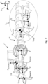
- FIG. 3 is a schematic representation of only the work machine 1 in an operating situation in which an attachment 15 is attached to the device interface 14.
- An ordering combination may be mentioned as an example of an attached attachment 15.
- the device interface load L includes coupling forces F Koppel,x and F Koppel,z acting in the x-direction and z-direction as well as a coupling moment M Koppel,y acting in the y-direction, which act in the coupling point 18 on the device interface 14.
- a trailed attachment 15 which is designed for soil cultivation
- tool forces exerted on tools 16 of the attachment 15 are determined via the tractive power and current driving speed of the work machine 1, a coupling torque M Kop-pel acting from the attachment 15 on the work machine 1, y and a vertical coupling force F coupling,z determined by means of attachment geometry, which is determined from the attachment configuration, and a moment balance formed around a support wheel arrangement 17.
- the vertical axle load F RA,z acting on one of the axles 2, 3, in particular the rear axle 3, is determined.
- an estimation of the rolling resistance is carried out in a first step to determine the coupling forces F Koppel,x and F Koppel,z .
- the vertical axle load F RA,z acting on one of the axles 2, 3, in particular the rear axle 3, is determined.
- the axle load ratio is determined from the vertical axle loads F FA,z , F RA,z currently acting on the axles 2, 3 determined and in the fourth step an estimate of the drive torques M FA,y and M RA,y on the axes 2, 3 of the work machine 1 is carried out.
- an estimate of a driving force coefficient can be made using variables determined in the first and second steps, the weight forces F Fw,x , F G,tractor,x , F G,imp,x , the force in x caused by the support wheel arrangement -Direction F Roller,x , as well as the vertical axle loads F FA,z , F RA,z on the front axle 2 and rear axle 3, for trailed or attached attachments 15.
- the attachment 15 can also be designed with containers, as already explained above.
- the variable filling volume of a container of the attachment 15 and/or the work machine 1 and/or the spatial arrangement of the container 11 in relation to the work machine 1 is taken into account when determining the dynamically changing vertical axle loads F FA,z , F RA,z .
- the position or spatial arrangement of a container on the work machine 1 and the attachment 15 can be determined, among other things, by an operator input using the operating and display unit 8 from the work machine and attachment configuration stored in the storage unit 10.
- the change in fill level can be detected using sensors.
- the initial ballasting includes data on the empty weight of the working machine 1, the initial axle load distribution, and a coupling torque, provided that a trailed attachment 15 with a torque-transmitting traction force amplifier is used.
- knowledge of the center of gravity S imp of the attachment 15 is relevant.
- a dialog-based process can be specified by the driver assistance system 7.
- the operator can be instructed via the operating and display unit 8 via a natural language dialogue in order to carry out the necessary steps and inputs.
- a sequence of steps can be provided that includes weighing on a scale.
- the proportional weight of the work machine 1 can first be recorded, which only has the front axle 2 on the scales.
- a measurement routine can then be carried out, by means of which an initial vertical axle load is determined by the sensor arrangement 13.
- the work machine 1 is then completely moved onto the scales and weighed.
- the fuel level in container 11 is determined.
- an attachment calibration which is carried out after the attachment 15 has been attached or attached.
- the proportional weight of the work machine 1 with the attachment 15 arranged on it will be recorded here, which only stands on the scales with the front axle 2.
- the measurement routine can then be carried out, by means of which the initial vertical axle load is determined by the sensor arrangement 13, taking the attachment 15 into account. If a traction booster is provided in the case of the attached attachment 15, this is switched on and the proportional weighing and the subsequent measuring routine are carried out again. The traction booster is then switched off.
- the work machine 1 with attached or attached attachment 15 is then moved onto the scales, with only the axes 2, 3 of the work machine 1 being on the scales.
- the at least one optional support wheel arrangement 17 of the attachment 15 or wheels of an attachment 15 designed as a transport trolley or slurry tank are not on the scales. After the weight of the working device 1 has been recorded, the entire working system is moved onto the scales in order to determine the total weight. Subsequently, to determine the weight acting on at least one attachment axle, the attachment 15 with its at least one support wheel arrangement 17 or the vehicle axles is moved onto the scales in order to record the weight of the attachment axle.
- the driver assistance system 7 can be used to compare the vertical axle loads F FA,z , F RA,z and the axle load distribution that are cyclically determined during the execution of the work process with limit values. If one of the limit values is passed, at least one warning message can be issued using the operating and display unit 8. The operator can thereby be made aware at an early stage of an operating situation in which optimal operation of the work system is not possible with the existing operating parameters.
- the driver assistance system 7 can determine an adjustment of at least one operating parameter when one of the limit values is passed, which is suggested to the operator for manual selection and/or implementation by means of the operating and display unit 8 and/or is automatically implemented by the driver assistance system 7.
Applications Claiming Priority (1)
| Application Number | Priority Date | Filing Date | Title |
|---|---|---|---|
| DE102022121568.7A DE102022121568A1 (de) | 2022-08-25 | 2022-08-25 | Verfahren zum Betreiben eines landwirtschaftlichen Arbeitssystems |
Publications (1)
| Publication Number | Publication Date |
|---|---|
| EP4327639A1 true EP4327639A1 (fr) | 2024-02-28 |
Family
ID=86851249
Family Applications (1)
| Application Number | Title | Priority Date | Filing Date |
|---|---|---|---|
| EP23179406.6A Pending EP4327639A1 (fr) | 2022-08-25 | 2023-06-15 | Procédé de fonctionnement d'un système de travail agricole |
Country Status (3)
| Country | Link |
|---|---|
| US (1) | US20240065132A1 (fr) |
| EP (1) | EP4327639A1 (fr) |
| DE (1) | DE102022121568A1 (fr) |
Citations (4)
| Publication number | Priority date | Publication date | Assignee | Title |
|---|---|---|---|---|
| US6119786A (en) * | 1999-09-10 | 2000-09-19 | Caterpillar Inc. | Method and apparatus for controlling a hitch system on a work machine |
| US20160039480A1 (en) * | 2014-08-05 | 2016-02-11 | Agco International Gmbh | Tractor control system |
| DE102015114262A1 (de) | 2015-08-27 | 2017-03-02 | Claas Tractor Sas | Vorrichtung und Verfahren zum Erfassen von auf eine Achse einwirkenden Kräften sowie Achsanordnung |
| DE102017205827A1 (de) * | 2017-04-05 | 2018-10-11 | Deere & Company | Verfahren zur Bereitstellung eines Ballastierungsvorschlags eines landwirtschaftlichen Traktors |
-
2022
- 2022-08-25 DE DE102022121568.7A patent/DE102022121568A1/de active Pending
-
2023
- 2023-06-15 EP EP23179406.6A patent/EP4327639A1/fr active Pending
- 2023-08-24 US US18/237,731 patent/US20240065132A1/en active Pending
Patent Citations (4)
| Publication number | Priority date | Publication date | Assignee | Title |
|---|---|---|---|---|
| US6119786A (en) * | 1999-09-10 | 2000-09-19 | Caterpillar Inc. | Method and apparatus for controlling a hitch system on a work machine |
| US20160039480A1 (en) * | 2014-08-05 | 2016-02-11 | Agco International Gmbh | Tractor control system |
| DE102015114262A1 (de) | 2015-08-27 | 2017-03-02 | Claas Tractor Sas | Vorrichtung und Verfahren zum Erfassen von auf eine Achse einwirkenden Kräften sowie Achsanordnung |
| DE102017205827A1 (de) * | 2017-04-05 | 2018-10-11 | Deere & Company | Verfahren zur Bereitstellung eines Ballastierungsvorschlags eines landwirtschaftlichen Traktors |
Also Published As
| Publication number | Publication date |
|---|---|
| DE102022121568A1 (de) | 2024-03-07 |
| US20240065132A1 (en) | 2024-02-29 |
Similar Documents
| Publication | Publication Date | Title |
|---|---|---|
| EP3384746B1 (fr) | Procédé pour fournir une proposition de contrepoids pour un tracteur agricole | |
| DE102016118205A1 (de) | Zugmaschinen-Geräte-Kombination mit Fahrerassistenzsystem | |
| EP3216628B1 (fr) | Dispositif de surveillance de pression de pneus | |
| DE102017215588A1 (de) | Vorrichtung, System und Verfahren zur Bestimmung von Achslasten eines landwirtschaftlichen Fahrzeugs mit einem Heckkraftheber | |
| EP3338522B1 (fr) | Dispositif et procédé de réglage du fonctionnement d'un outil porté hydraulique d'un véhicule | |
| DE102020102330A1 (de) | Zugmaschine | |
| EP3804486A1 (fr) | Engin de travail pour l'agriculture et son procédé de commande | |
| EP3932158A1 (fr) | Tracteur et procédé de fonctionnement d'un tracteur | |
| EP1493599B1 (fr) | Installation de réglage de la pression de pneus | |
| EP3639640B1 (fr) | Système de travail agricole | |
| EP3202244B1 (fr) | Détection de force de traction sur un véhicule ayant une liaison | |
| DE102012216306A1 (de) | Verfahren zum Bestimmen einer Beladung einer Arbeitsmaschine, Verwendung eines Kraftsensors eines Hubwerks einer Arbeitsmaschine zum Bestimmen einer Beladung der Arbeitsmaschine, Steuergerät, Fahrzeugsteuersystem, Arbeitsmaschine und Programm | |
| EP4327639A1 (fr) | Procédé de fonctionnement d'un système de travail agricole | |
| EP4059743A1 (fr) | Procédé de régulation automatique de la pression interne de pneus de roue | |
| DE102019115301B4 (de) | Steuerungs- und/oder Regelvorrichtung und Verfahren zum Betrieb eines Anbaugerätes an einem Fahrzeug | |
| DE102017114917A1 (de) | Landwirtschaftliches Arbeitsfahrzeug | |
| DE102015114262A1 (de) | Vorrichtung und Verfahren zum Erfassen von auf eine Achse einwirkenden Kräften sowie Achsanordnung | |
| DE102022121569A1 (de) | Verfahren zum Betreiben eines landwirtschaftlichen Arbeitssystems | |
| EP2653324B1 (fr) | Moissonneuse agricole | |
| EP3398424B1 (fr) | Machine de distribution | |
| DE102017126417A1 (de) | Landwirtschaftliches Fahrzeug | |
| EP3925423A1 (fr) | Système de travail agricole | |
| DE102016106009A1 (de) | Landwirtschaftliches Fahrzeug | |
| DE102021134214A1 (de) | Konfigurationssystem und Verfahren zum Betreiben einer landwirtschaftlichen Arbeitsmaschine sowie landwirtschaftliche Arbeitsmaschine | |
| DE102021133763A1 (de) | Verfahren zur Ladungsüberwachung eines Fahrzeuggespanns |
Legal Events
| Date | Code | Title | Description |
|---|---|---|---|
| PUAI | Public reference made under article 153(3) epc to a published international application that has entered the european phase |
Free format text: ORIGINAL CODE: 0009012 |
|
| STAA | Information on the status of an ep patent application or granted ep patent |
Free format text: STATUS: THE APPLICATION HAS BEEN PUBLISHED |
|
| AK | Designated contracting states |
Kind code of ref document: A1 Designated state(s): AL AT BE BG CH CY CZ DE DK EE ES FI FR GB GR HR HU IE IS IT LI LT LU LV MC ME MK MT NL NO PL PT RO RS SE SI SK SM TR |
|
| P01 | Opt-out of the competence of the unified patent court (upc) registered |
Effective date: 20240228 |