EP4327418B1 - Apparatus and method for reducing thermal blooming in an optical subsystem of a high energy laser - Google Patents
Apparatus and method for reducing thermal blooming in an optical subsystem of a high energy laser Download PDFInfo
- Publication number
- EP4327418B1 EP4327418B1 EP22718400.9A EP22718400A EP4327418B1 EP 4327418 B1 EP4327418 B1 EP 4327418B1 EP 22718400 A EP22718400 A EP 22718400A EP 4327418 B1 EP4327418 B1 EP 4327418B1
- Authority
- EP
- European Patent Office
- Prior art keywords
- fluid
- hel
- combustion chamber
- optical subsystem
- concentration
- Prior art date
- Legal status (The legal status is an assumption and is not a legal conclusion. Google has not performed a legal analysis and makes no representation as to the accuracy of the status listed.)
- Active
Links
Images

Classifications
-
- H—ELECTRICITY
- H01—ELECTRIC ELEMENTS
- H01S—DEVICES USING THE PROCESS OF LIGHT AMPLIFICATION BY STIMULATED EMISSION OF RADIATION [LASER] TO AMPLIFY OR GENERATE LIGHT; DEVICES USING STIMULATED EMISSION OF ELECTROMAGNETIC RADIATION IN WAVE RANGES OTHER THAN OPTICAL
- H01S3/00—Lasers, i.e. devices using stimulated emission of electromagnetic radiation in the infrared, visible or ultraviolet wave range
- H01S3/005—Optical devices external to the laser cavity, specially adapted for lasers, e.g. for homogenisation of the beam or for manipulating laser pulses, e.g. pulse shaping
-
- F—MECHANICAL ENGINEERING; LIGHTING; HEATING; WEAPONS; BLASTING
- F41—WEAPONS
- F41H—ARMOUR; ARMOURED TURRETS; ARMOURED OR ARMED VEHICLES; MEANS OF ATTACK OR DEFENCE, e.g. CAMOUFLAGE, IN GENERAL
- F41H13/00—Means of attack or defence not otherwise provided for
- F41H13/0043—Directed energy weapons, i.e. devices that direct a beam of high energy content toward a target for incapacitating or destroying the target
- F41H13/005—Directed energy weapons, i.e. devices that direct a beam of high energy content toward a target for incapacitating or destroying the target the high-energy beam being a laser beam
Definitions
- the present subject matter relates generally to a high energy laser (HEL), and more particularly, to an apparatus and method for reducing thermal blooming in an optical subsystem of an HEL.
- HEL high energy laser
- HEL's provide the ability to engage objects at a distance with precision.
- the effectiveness of a HEL in operation largely depends upon the HEL beam quality developed in an optical subsystem of the HEL.
- clean dry air (CDA) is introduced into the optical subsystem.
- CDA clean dry air
- the purging of the optical subsystem with CDA maintains a positive pressure within the optical subsystem to reduce or prevent the introduction of contaminants therein.
- CDA is generally not used as the purging agent during emission of the HEL because CDA includes diatomic oxygen in amounts that result in a phenomenon known as "thermal blooming." This phenomenon results from the absorption of HEL energy by diatomic oxygen creating heat and an undesired distortion of the laser beam.
- One way to minimize/prevent thermal blooming is to use nitrogen in place of at least some of the diatomic oxygen in the gas introduced into the optical subsystem just before and during laser emission, so that the concentration of diatomic oxygen is reduced and replaced by the nitrogen. While effective, the use of nitrogen involves other issues. First, nitrogen must be stored in a container and transported with the HEL.
- the nitrogen container is carried by a vehicle or on or adjacent to a platform on which the HEL is installed and must be refilled at depot filling stations, which may be problematic in the case of distant or remote operations.
- Current nitrogen containers may limit operational use of the HEL to approximately three days. Once the nitrogen is expelled from the container, the HEL can only operate at reduced effectiveness at best until the container is replenished.
- a high-pressure nitrogen container may deteriorate over time and may unexpectedly release its contents, creating a projectile that may injure personnel. Still further, even a slow leak from a high-pressure nitrogen container can create the potential for operator asphyxiation.
- oxygen depleted gas can be used in place of the nitrogen as the purging fluid.
- Oxygen depleted gas can be generated using a number of chemical or molecular separation systems but are currently disadvantageous in mobile applications because the systems must be oriented with respect to gravity in order to perform properly. Additionally, the chemical or molecular separation systems are typically large and heavy and require considerable electrical power to operate.
- FUHS ALLENE "Overview Of Aero-Optical Phenomena", PROCEEDINGS OF SPIE, IEEE, US, vol. 293, 30 December 1981 (1981-12-30), pages 36-55, XP060032786 , discloses a laser device that uses helium or dry nitrogen supplied to an optical subsystem to reduce thermal blooming.
- 5,811,753 discloses an apparatus to remove gases affecting the power of a laser beam, wherein it is noted that laser beam absorbing gases are a known source of thermal blooming in a beam delivery tube of a laser.
- U. S. Published Patent Application No. 2006/0187996 discloses a high power laser including an apparatus that purges impurities at a vicinity of a mirror and lens in an optical subsystem of the laser. However, the above-mentioned issues are not solved.
- an apparatus for reducing thermal blooming in an optical subsystem of an HEL comprises a fluid pump that receives a first fluid containing diatomic oxygen at a first concentration, and a combustion chamber that combusts the first fluid to develop a second fluid containing diatomic oxygen at a second concentration, wherein the second concentration is less than the first concentration, and wherein the second fluid is supplied to the optical subsystem of the HEL.
- a method of operating an HEL having an optical subsystem comprises the steps of providing a first fluid containing diatomic oxygen at a first concentration to a combustion chamber, combusting the first fluid in the combustion chamber to develop a second fluid containing diatomic oxygen at a second concentration less than the first concentration, and supplying the second fluid to the optical subsystem of the HEL.
- a fluid supply system 100 includes an oxygen depletion apparatus 102 that provides an oxygen depleted fluid to an optical subsystem 104 of an HEL 106. More particularly, the oxygen depletion apparatus 102 includes a control system 108, a fluid pump 110, and a combustion chamber 112, which is preferably a catalytic combustion chamber. The system 102 further comprises a fuel reservoir 114, a control valve 116, and a fluid filter/dryer device 118, preferably comprising at least one filter device and at least one dryer device. Additional conduits, valves, filter/drying devices, and other instrumentation (not shown) may be used in the system 100.
- the control system 108 of the oxygen depletion apparatus 102 is coupled to the fluid pump 110, the combustion chamber 112, the control valve 116, and the HEL 106.
- the combustion chamber 112 is also coupled to the fluid pump 110, an outlet port of the control valve 116, and the fluid filter/dryer device 118.
- the control valve 116 further includes an inlet port coupled to a fuel reservoir 114, wherein fuel may be controllably transferred from the fuel reservoir 114 to the combustion chamber 112 through the control valve 116.
- the fluid filter/dryer device 118 is coupled to the optical subsystem 104 of the HEL 106.
- the oxygen depletion apparatus 102 is relatively insensitive to changes in orientation, shock, vibration, or humidity levels during use.
- the control system 108 Upon actuation of the HEL 106, the control system 108 operates the various components in one of standby, ready, and emission states as determined by signals supplied by automatic or user-operated signaling devices 119, 120, and 122.
- the standby state 119 is implemented as a default state when the HEL 106 is operational but not being prepared for or not in use.
- the ready state 120 is operational when the HEL 106 is ready for immediate emission.
- the emission state 122 is operational during emission of a laser beam from the HEL 106.
- the control system 108 actuates the fluid pump 110 to draw in a first fluid from outside the fluid pump 110 and transfer the first fluid having a first diatomic oxygen concentration to the combustion chamber 112.
- the combustion chamber is deactuated during operation in the standby state and the first fluid is transferred to the fluid filter/dryer device 118 to clean and dry the first fluid.
- the clean and dried first fluid is then supplied to the optical subsystem 104 to purge the HEL beam path of contaminants.
- the fluid pump 110 is an air pump that draws ambient air.
- the flow rate of the air pump may be about 0.25 L/min to 1.00 L/min per 1.00 L of purged volume in the HEL 106, more preferably from about 0.50 L/min to 1.00 L/min, and most preferably 1.00 L/min.
- the control system 108 actuates the fluid pump 110 to draw in the first fluid from outside the fluid pump 110 and transfer the first fluid to the combustion chamber 112.
- the flow rate of the fluid pump may be about 0.25 L/min to 1.00 L/min per 1.00 L of purged volume in the HEL 106, more preferably from about 0.50 L/min to 1.00 L/min, and most preferably 1.00 L/min.
- the control system actuates the combustion chamber 112 so as to combust the first fluid within the combustion chamber 112.
- the combustion chamber size is about 5% of the HEL purge volume.
- the first fluid provided to the combustion chamber 112 comprises a first concentration of diatomic oxygen.
- the first concentration of diatomic oxygen in the first fluid is from about 19.5% to 23.5%, preferably about 21%.
- the control system 108 actuates the control valve 116 to an open position wherein fuel located within the fuel reservoir 114 is transferred from the fuel reservoir 114 through the control valve 116 to the combustion chamber 112.
- the flow rate through the control valve 116 is from about 6.25 ⁇ 10 -5 L/min to 2.50 ⁇ 10 -4 L/min per 1.00 L of purged volume in the HEL 106, more preferably from about 1.25x10 -4 L/min to 2.50x10 -4 L/min, and most preferably 2.50x10 -4 L/min.
- Combustion of the first fluid in the combustion chamber 112 rapidly develops an oxygen depleted second fluid comprising a second concentration of diatomic oxygen wherein the concentration of diatomic oxygen in the second fluid is less than the concentration of diatomic oxygen in the first fluid.
- the second fluid may contain between about 0% and about 67% less diatomic oxygen, and more preferably between about 33% and 67% less diatomic oxygen.
- the second fluid is transferred to and engages the fluid filter/dryer device 118, which reduces combustion byproducts such as carbon monoxide, carbon dioxide, water vapor, and unburned fuel that may be contained in the second fluid and that may distort the HEL beam.
- the fluid filter/dryer device 118 may remove contaminants exceeding 20 microns and reduce dew points from about 100°C to about minus 40°C, and most preferably about minus 40°C.
- the second fluid is supplied to the optical subsystem 104 to purge the HEL beam path of the optical subsystem 104.
- the control system 108 may operate the HEL 106 in the emission state to emit a laser beam through the optical subsystem 104.
- the HEL beam may be from about 1 cm to about 10 cm in diameter and produce a peak power from about 10,000 W to about 1,000,000 W.
- the second fluid within the beam path having a lower diatomic oxygen concentration reduces the amount of HEL beam distortion by diatomic oxygen resulting in less thermal blooming within the beam path of the HEL 106 and a high HEL beam quality.
- the relative reduction in diatomic oxygen is proportional to the relative reduction in thermal blooming during emission of the HEL beam from the HEL 106.
- the oxygen depletion apparatus 102 may develop the oxygen depleted second fluid having a second diatomic oxygen concentration in a temperature range from about minus 40°C to about 71°C. Furthermore, the system 102 may develop the second fluid under any atmospheric or ambient pressure.
- receiving and transmitting of signals or data means that two or more systems or components are capable of communicating with each other via signals that travel over some type of signal path.
- the signals may be communication, power, data, or energy signals, which may communicate information, power, or energy from a first system or component to a second system or component along a signal path between the first and second system or component.
- the signal paths may include physical, electrical, magnetic, electromagnetic, electrochemical, optical, wired, or wireless connections.
- the signal paths may also include additional systems or components between the first and second system or component.
- the control system 108 actuates the fluid pump 110 and the control valve 116, wherein the fluid pump 110 draws in the first fluid in the form of ambient air from outside the fluid pump 110 and transfers the first fluid having the first diatomic oxygen concentration to the deactuated combustion chamber 112.
- the combustion chamber 112 is deactuated (step 224) and the first fluid having the first diatomic oxygen concentration is transferred from the deactuated combustion chamber 112 to the fluid filter/dryer device 118 wherein the first fluid is cleaned and dried.
- the first fluid is supplied at step 206 to the optical subsystem 104 to purge the HEL beam path of contaminants.
- the oxygen depletion apparatus 102 creates a diatomic oxygen depleted second fluid via controlled combustion of a first fluid to reduce thermal blooming inside the beam path of an HEL 106.
- the rapid, light weight, and robust combustion to develop the second fluid from the first fluid may be undertaken over a wide range of temperatures, pressures, and flow rates, thus providing the ability to retrofit an existing HEL regardless of orientation, and provides a system not sensitive to shock, vibration, or humidity levels during use.
Landscapes
- Physics & Mathematics (AREA)
- Electromagnetism (AREA)
- Engineering & Computer Science (AREA)
- Optics & Photonics (AREA)
- Plasma & Fusion (AREA)
- Radar, Positioning & Navigation (AREA)
- Remote Sensing (AREA)
- General Engineering & Computer Science (AREA)
- Lasers (AREA)
Description
- The present subject matter relates generally to a high energy laser (HEL), and more particularly, to an apparatus and method for reducing thermal blooming in an optical subsystem of an HEL.
- Whether in the air, on land, or at sea, HEL's provide the ability to engage objects at a distance with precision. The effectiveness of a HEL in operation largely depends upon the HEL beam quality developed in an optical subsystem of the HEL. Generally, prior to implementation of a "ready" state of the HEL, clean dry air (CDA) is introduced into the optical subsystem. The purging of the optical subsystem with CDA maintains a positive pressure within the optical subsystem to reduce or prevent the introduction of contaminants therein. However, while feasible, CDA is generally not used as the purging agent during emission of the HEL because CDA includes diatomic oxygen in amounts that result in a phenomenon known as "thermal blooming." This phenomenon results from the absorption of HEL energy by diatomic oxygen creating heat and an undesired distortion of the laser beam. One way to minimize/prevent thermal blooming is to use nitrogen in place of at least some of the diatomic oxygen in the gas introduced into the optical subsystem just before and during laser emission, so that the concentration of diatomic oxygen is reduced and replaced by the nitrogen. While effective, the use of nitrogen involves other issues. First, nitrogen must be stored in a container and transported with the HEL. Generally, the nitrogen container is carried by a vehicle or on or adjacent to a platform on which the HEL is installed and must be refilled at depot filling stations, which may be problematic in the case of distant or remote operations. Current nitrogen containers may limit operational use of the HEL to approximately three days. Once the nitrogen is expelled from the container, the HEL can only operate at reduced effectiveness at best until the container is replenished. Furthermore, a high-pressure nitrogen container may deteriorate over time and may unexpectedly release its contents, creating a projectile that may injure personnel. Still further, even a slow leak from a high-pressure nitrogen container can create the potential for operator asphyxiation.
- As an alternative to nitrogen, oxygen depleted gas can be used in place of the nitrogen as the purging fluid. Oxygen depleted gas can be generated using a number of chemical or molecular separation systems but are currently disadvantageous in mobile applications because the systems must be oriented with respect to gravity in order to perform properly. Additionally, the chemical or molecular separation systems are typically large and heavy and require considerable electrical power to operate.
FUHS ALLENE: "Overview Of Aero-Optical Phenomena", PROCEEDINGS OF SPIE, IEEE, US, vol. 293, 30 December 1981 (1981-12-30), pages 36-55, XP060032786, discloses a laser device that uses helium or dry nitrogen supplied to an optical subsystem to reduce thermal blooming.
U. S. Patent No. 5,811,753 discloses an apparatus to remove gases affecting the power of a laser beam, wherein it is noted that laser beam absorbing gases are a known source of thermal blooming in a beam delivery tube of a laser.
U. S. Published Patent Application No. 2006/0187996 discloses a high power laser including an apparatus that purges impurities at a vicinity of a mirror and lens in an optical subsystem of the laser. However, the above-mentioned issues are not solved. - The invention is set out in the annexed claims. According to one aspect, an apparatus for reducing thermal blooming in an optical subsystem of an HEL comprises a fluid pump that receives a first fluid containing diatomic oxygen at a first concentration, and a combustion chamber that combusts the first fluid to develop a second fluid containing diatomic oxygen at a second concentration, wherein the second concentration is less than the first concentration, and wherein the second fluid is supplied to the optical subsystem of the HEL.
- According to another aspect a method of operating an HEL having an optical subsystem comprises the steps of providing a first fluid containing diatomic oxygen at a first concentration to a combustion chamber, combusting the first fluid in the combustion chamber to develop a second fluid containing diatomic oxygen at a second concentration less than the first concentration, and supplying the second fluid to the optical subsystem of the HEL.
- Other aspects and advantages will become apparent upon consideration of the following detailed description and the attached drawings wherein like numerals designate like structures throughout the specification.
-
-
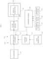
FIG. 1 is a block diagram of an exemplary system comprising an oxygen depletion apparatus and an optical subsystem of a HEL; and -
FIG. 2 is a flowchart of programming executed by the control system ofFIG. 1 to implement an exemplary method according to an embodiment. - Referring to
FIG. 1 , afluid supply system 100 includes anoxygen depletion apparatus 102 that provides an oxygen depleted fluid to anoptical subsystem 104 of anHEL 106. More particularly, theoxygen depletion apparatus 102 includes acontrol system 108, afluid pump 110, and acombustion chamber 112, which is preferably a catalytic combustion chamber. Thesystem 102 further comprises afuel reservoir 114, acontrol valve 116, and a fluid filter/dryer device 118, preferably comprising at least one filter device and at least one dryer device. Additional conduits, valves, filter/drying devices, and other instrumentation (not shown) may be used in thesystem 100. - As illustrated in
FIG. 1 , thecontrol system 108 of theoxygen depletion apparatus 102 is coupled to thefluid pump 110, thecombustion chamber 112, thecontrol valve 116, and theHEL 106. Thecombustion chamber 112 is also coupled to thefluid pump 110, an outlet port of thecontrol valve 116, and the fluid filter/dryer device 118. Thecontrol valve 116 further includes an inlet port coupled to afuel reservoir 114, wherein fuel may be controllably transferred from thefuel reservoir 114 to thecombustion chamber 112 through thecontrol valve 116. Still further, the fluid filter/dryer device 118 is coupled to theoptical subsystem 104 of theHEL 106. Advantageously, theoxygen depletion apparatus 102 is relatively insensitive to changes in orientation, shock, vibration, or humidity levels during use. - Upon actuation of the
HEL 106, thecontrol system 108 operates the various components in one of standby, ready, and emission states as determined by signals supplied by automatic or user-operatedsignaling devices standby state 119 is implemented as a default state when theHEL 106 is operational but not being prepared for or not in use. Theready state 120 is operational when the HEL 106 is ready for immediate emission. Theemission state 122 is operational during emission of a laser beam from theHEL 106. - More particularly, during operation in the standby state, the
control system 108 actuates thefluid pump 110 to draw in a first fluid from outside thefluid pump 110 and transfer the first fluid having a first diatomic oxygen concentration to thecombustion chamber 112. The combustion chamber is deactuated during operation in the standby state and the first fluid is transferred to the fluid filter/dryer device 118 to clean and dry the first fluid. The clean and dried first fluid is then supplied to theoptical subsystem 104 to purge the HEL beam path of contaminants. In an embodiment, thefluid pump 110 is an air pump that draws ambient air. The flow rate of the air pump may be about 0.25 L/min to 1.00 L/min per 1.00 L of purged volume in theHEL 106, more preferably from about 0.50 L/min to 1.00 L/min, and most preferably 1.00 L/min. - During operation in the ready state, the
control system 108 actuates thefluid pump 110 to draw in the first fluid from outside thefluid pump 110 and transfer the first fluid to thecombustion chamber 112. The flow rate of the fluid pump may be about 0.25 L/min to 1.00 L/min per 1.00 L of purged volume in theHEL 106, more preferably from about 0.50 L/min to 1.00 L/min, and most preferably 1.00 L/min. Furthermore, the control system actuates thecombustion chamber 112 so as to combust the first fluid within thecombustion chamber 112. In an embodiment, the combustion chamber size is about 5% of the HEL purge volume. The first fluid provided to thecombustion chamber 112 comprises a first concentration of diatomic oxygen. In an embodiment, the first concentration of diatomic oxygen in the first fluid is from about 19.5% to 23.5%, preferably about 21%. Additionally, thecontrol system 108 actuates thecontrol valve 116 to an open position wherein fuel located within thefuel reservoir 114 is transferred from thefuel reservoir 114 through thecontrol valve 116 to thecombustion chamber 112. In an embodiment, the flow rate through thecontrol valve 116 is from about 6.25×10⁻⁵ L/min to 2.50×10⁻⁴ L/min per 1.00 L of purged volume in theHEL 106, more preferably from about 1.25x10⁻⁴ L/min to 2.50x10⁻⁴ L/min, and most preferably 2.50x10⁻⁴ L/min. Combustion of the first fluid in thecombustion chamber 112 rapidly develops an oxygen depleted second fluid comprising a second concentration of diatomic oxygen wherein the concentration of diatomic oxygen in the second fluid is less than the concentration of diatomic oxygen in the first fluid. In an embodiment, the second fluid may contain between about 0% and about 67% less diatomic oxygen, and more preferably between about 33% and 67% less diatomic oxygen. The second fluid is transferred to and engages the fluid filter/dryer device 118, which reduces combustion byproducts such as carbon monoxide, carbon dioxide, water vapor, and unburned fuel that may be contained in the second fluid and that may distort the HEL beam. In one embodiment, the fluid filter/dryer device 118 may remove contaminants exceeding 20 microns and reduce dew points from about 100°C to about minus 40°C, and most preferably about minus 40°C. Upon exiting the fluid filter/dryer device 118, the second fluid is supplied to theoptical subsystem 104 to purge the HEL beam path of theoptical subsystem 104. - Upon purging the beam path of the
optical subsystem 104 with the second fluid, thecontrol system 108 may operate theHEL 106 in the emission state to emit a laser beam through theoptical subsystem 104. In an embodiment, the HEL beam may be from about 1 cm to about 10 cm in diameter and produce a peak power from about 10,000 W to about 1,000,000 W. The second fluid within the beam path having a lower diatomic oxygen concentration reduces the amount of HEL beam distortion by diatomic oxygen resulting in less thermal blooming within the beam path of theHEL 106 and a high HEL beam quality. The relative reduction in diatomic oxygen is proportional to the relative reduction in thermal blooming during emission of the HEL beam from theHEL 106. For example, the relative reduction in thermal blooming is equal to 1 - (SFO/FFO)2, wherein SFO is the diatomic oxygen concentration of the second fluid, and FFO is the diatomic oxygen concentration of the first fluid. In one embodiment wherein the first fluid contains about 21% diatomic oxygen and the second fluid contains about 14% diatomic oxygen, the relative reduction in thermal blooming is about 56%. - In one embodiment, the relative reduction in thermal blooming may be further enhanced wherein the
combustion chamber 112 is a catalytic combustion chamber. In general, a catalytic combustion system incorporates metals, such as platinum, to reduce hydrocarbon emission such as carbon monoxide and unburned fuel. The combustion within thecatalytic combustion chamber 112 develops and heats the second fluid but in a flameless environment. In one embodiment, thecatalytic combustion chamber 112 develops a second fluid with a second diatomic oxygen concentration and heat. In another embodiment, propane is stored in thefuel reservoir 114, and is used as the fuel in the combustion process within the catalytic combustion chamber. In this embodiment, the diatomic oxygen concentration of the second fluid is reduced to about 8.8% reducing thermal blooming by about 82%. In general, theoxygen depletion apparatus 102 reduces thermal blooming from about 10% to about 82%, and most preferably about 82%. - In one embodiment, the combustion process is undertaken only during operation in the ready state and the emission state so as to minimize fuel consumption for greater operational availability. As described above, any combustible gas or liquid fuel may be stored in the
fuel reservoir 114. In one embodiment, the fuel is jet fuel, liquid gasoline or diesel fuel. In another embodiment, the fuel is any gaseous or liquid hydrocarbon, such as methane, or propane. In cases where theHEL 106 is installed on a powered vehicle, the fuel may be the same that is used for vehicle propulsion, so that there is no need for a dedicated fuel source and associated equipment. - In another embodiment, upon exhaustion of fuel within the
fuel reservoir 114, thesystem 102 may continue to emit an HEL beam using the clean and dry first fluid as the purging fluid, but at a performance reduction until thefuel reservoir 114 can be replenished. As should be evident from the foregoing, the performance reduction is directly related to the amount of diatomic oxygen present in the purging fluid. - Generally, the
oxygen depletion apparatus 102 may develop the oxygen depleted second fluid having a second diatomic oxygen concentration in a temperature range from about minus 40°C to about 71°C. Furthermore, thesystem 102 may develop the second fluid under any atmospheric or ambient pressure. - Also, it should be apparent to those who have skill in the art that any combination of hardware and/or software may be used to implement any or all of the system or components thereof described herein. It will be understood and appreciated that one or more of the processes, sub-processes, and process steps described in connection with the FIGS. may be performed by hardware, software, or a combination of hardware and software on one or more electronic or digitally controlled devices. The software may reside in a software memory (not shown) in a suitable electronic processing component or system such as, for example, the
control system 108. The software memory may include an ordered listing of executable instructions for implementing logical functions (that is, "logic" that may be implemented in digital form such as digital circuitry or source code, or in analog form such as analog source such as an analog electrical, sound, or video signal). The instructions may be executed within thecontrol system 108 that may include, for example, one or more microprocessors, general purpose processors, combinations of processors, digital signal processors (DSPs), field programmable gate arrays (FPGAs), or application-specific integrated circuits (ASICs). The embodiments described in this application may be implemented in a variety of configurations and operate as hardware/software components in a single hardware/software unit, or in separate hardware/software units. - The executable instructions may be implemented as a computer program product having instructions stored therein which, when executed by a processing module of an electronic system, direct the electronic system to carry out the instructions. The computer program product may be selectively embodied in any non-transitory computer-readable storage medium for use by or in connection with an instruction execution system, apparatus, or device, such as an electronic computer-based system, processor-containing system, or other system that may selectively fetch the instructions from the instruction execution system, apparatus, or device and execute the instructions. In the context of this document, a computer-readable storage medium is any non-transitory means that may store the program for use by or in connection with the instruction execution system, apparatus, or device. The non-transitory computer-readable storage medium may selectively be, for example, an electronic, magnetic, optical, electromagnetic, infrared, or semiconductor system, apparatus, or device. A non-exhaustive list of more specific examples of non-transitory computer readable media include: an electrical connection having one or more wires (electronic); a portable computer disk or diskette (magnetic); a random access, i.e., volatile, memory (electronic); a read-only memory (electronic); an erasable programmable read only memory such as, for example, flash memory (electronic); a compact disc memory such as, for example, CD-ROM, CD-R, CD-RW (optical); and digital versatile disc memory, i.e., DVD (optical).
- It will also be understood that receiving and transmitting of signals or data as used in this document means that two or more systems or components are capable of communicating with each other via signals that travel over some type of signal path. The signals may be communication, power, data, or energy signals, which may communicate information, power, or energy from a first system or component to a second system or component along a signal path between the first and second system or component. The signal paths may include physical, electrical, magnetic, electromagnetic, electrochemical, optical, wired, or wireless connections. The signal paths may also include additional systems or components between the first and second system or component.
-
FIG. 2 illustrates the operation of thesystem 100. Atstep 200, thesystem 100 starts up in a selected operational state. In one embodiment, thesystem 100 is placed in an operational state when a mobile or stationary apparatus is engaged. For example, if theHEL 106 and thesystem 100 are carried by a mobile land use vehicle, thesystem 100 may be placed in an operational state upon engagement of the vehicle engine. In another embodiment, thesystem 100 is placed in an operational state upon engagement of a switch, button, or other control wherein the operator of theHEL 106 may place thesystem 100 in an operational state independent of the mobile or stationary apparatus. In an embodiment, the selected operational state may be thedefault standby state 119. - At
step 202, thecontrol system 108 actuates thefluid pump 110 and thecontrol valve 116, wherein thefluid pump 110 draws in the first fluid in the form of ambient air from outside thefluid pump 110 and transfers the first fluid having the first diatomic oxygen concentration to thedeactuated combustion chamber 112. - At
step 204, the first fluid is transferred from thedeactuated combustion chamber 112 to the fluid filter/dryer device 118 wherein the first fluid is cleaned and dried. Upon completion of the cleaning and drying of the first fluid, the first fluid is supplied atstep 206 to theoptical subsystem 104 to purge the HEL beam path of contaminants. Although not shown, thestep 206 may be continuously undertaken for a selected period of time before undertaking subsequent steps to ensure that effective purging has been accomplished. - At
step 208 thecontrol system 108 detects the commanded state of theHEL 106. If theHEL 106 is not being commanded to undertake the ready state and thecombustion chamber 112 is not actuated (step 222), clean and dried first fluid is supplied to theoptical subsystem 104 of theHEL 106. If thecontrol system 108 detects that theHEL 106 is being commanded to operate in the ready state, thecontrol system 108 commands thecontrol valve 116 to an open position so that fuel from thefuel reservoir 114 is transferred through thecontrol valve 116 to thecombustion chamber 112 and thecombustion chamber 112 is actuated by the control system 108 (steps 210 and 212). The first fluid having the first concentration of diatomic oxygen drawn from thefluid pump 110 is combusted in thecombustion chamber 112 to develop the second fluid having the second diatomic oxygen concentration wherein the second concentration is less than the first concentration of the first fluid. - At
step 214, the second fluid is cleaned and dried by the fluid filter/dryer device 118 and is transferred to theoptical subsystem 104 to purge the HEL beam path of theoptical subsystem 104. - At
step 216, thecontrol system 108 detects whether the emission state is commanded. If this is not the case, the second fluid continues to purge theoptical subsystem 104 of theHEL 106 of contaminants. If the emission state is commanded, atstep 218 the HEL beam is emitted through the purged beam path of theoptical subsystem 104 containing the second fluid. - At
step 220, thecontrol system 108 detects whether the emission state is still being commanded. If this is the case, the HEL beam continues to be emitted through theoptical subsystem 104 of theHEL 106. If the emission state is no longer commanded, thecontrol system 108 reverts to thestep 208. If theHEL 106 is being commanded to undertake the ready state, thecontrol system 108 again proceeds to thestep 210. If theHEL 106 is not being commanded to undertake the ready state and thecontrol system 108 determines that thecombustion chamber 112 is actuated (step 222), thecombustion chamber 112 is deactuated (step 224) and the first fluid having the first diatomic oxygen concentration is transferred from thedeactuated combustion chamber 112 to the fluid filter/dryer device 118 wherein the first fluid is cleaned and dried. Upon completion of the cleaning and drying of the first fluid, the first fluid is supplied atstep 206 to theoptical subsystem 104 to purge the HEL beam path of contaminants. - In summary, the
oxygen depletion apparatus 102 creates a diatomic oxygen depleted second fluid via controlled combustion of a first fluid to reduce thermal blooming inside the beam path of anHEL 106. The rapid, light weight, and robust combustion to develop the second fluid from the first fluid may be undertaken over a wide range of temperatures, pressures, and flow rates, thus providing the ability to retrofit an existing HEL regardless of orientation, and provides a system not sensitive to shock, vibration, or humidity levels during use. - The use of the terms "a" and "an" and "the" and similar references in the context of describing the invention (especially in the context of the following claims) are to be construed to cover both the singular and the plural, unless otherwise indicated herein or clearly contradicted by context. Recitation of ranges of values herein are merely intended to serve as a shorthand method of referring individually to each separate value falling within the range, unless otherwise indicated herein, and each separate value is incorporated into the specification as if it were individually recited herein. All methods described herein can be performed in any suitable order unless otherwise indicated herein or otherwise clearly contradicted by context. The use of any and all examples, or exemplary language (e.g., "such as") provided herein, is intended merely to better illuminate the disclosure and does not pose a limitation on the scope of the disclosure unless otherwise claimed. No language in the specification should be construed as indicating any non-claimed element as essential to the practice of the disclosure.
- Numerous modifications to the present disclosure will be apparent to those skilled in the art in view of the foregoing description. It should be understood that the illustrated embodiments are exemplary only and should not be taken as limiting the scope of the invention which is defined by the attached claims.
Claims (15)
- An apparatus for reducing thermal blooming in an optical subsystem (104) of a high energy laser, HEL, comprising:a fluid pump (110) that receives a first fluid containing diatomic oxygen at a first concentration; anda combustion chamber (112) that combusts the first fluid to develop a second fluid containing diatomic oxygen at a second concentration, wherein the second concentration is less than the first concentration, and wherein the second fluid is supplied to the optical subsystem (104) of the HEL (106).
- The apparatus of claim 1, further comprising a fluid filter/dryer device (118) in fluid communication between the combustion chamber and the optical subsystem.
- The apparatus of claim 2, wherein the fluid filter/dryer device comprises at least one of a filter device and at least one dryer device wherein the second fluid engages the at least one of a filter device and at least one dryer device.
- The apparatus of claim 1, wherein the first fluid is air.
- The apparatus of claim 1, wherein the fluid pump is an air pump.
- The apparatus of claim 1, wherein the combustion chamber is a catalytic combustion chamber.
- The apparatus of claim 1, further comprising a fuel reservoir; (114) and a control valve (116) wherein the control valve is coupled to the combustion chamber and the fuel reservoir.
- The apparatus of claim 7, further comprising a fuel within the fuel reservoir.
- The apparatus of claim 8, wherein the fuel is any gaseous or liquid hydrocarbon.
- The apparatus of claim 1, wherein the apparatus is insensitive to orientation.
- A method of operating a high energy laser, HEL, having an optical subsystem (104), the method comprising the steps of:providing a first fluid containing diatomic oxygen at a first concentration to a combustion chamber (112);combusting the first fluid in the combustion chamber to develop a second fluid containing diatomic oxygen at a second concentration less than the first concentration; andsupplying the second fluid to the optical subsystem of the HEL (106).
- The method of claim 11, further comprising the step of transferring the second fluid to a fluid filter/dryer device (118) in fluid communication between the combustion chamber and the optical subsystem.
- The method of claim 11, wherein the first fluid is air.
- The method of claim 11, wherein the combustion chamber is a catalytic combustion chamber.
- The method of claim 11, further comprising the step of engaging a control system (108) in fluid communication with the combustion device, wherein the control system input for the HEL is the ready state (120).
Applications Claiming Priority (2)
| Application Number | Priority Date | Filing Date | Title |
|---|---|---|---|
| US17/237,600 US12278455B2 (en) | 2021-04-22 | 2021-04-22 | Apparatus and method for reducing thermal blooming in an optical subsystem of a high energy laser |
| PCT/US2022/022483 WO2022225663A1 (en) | 2021-04-22 | 2022-03-30 | Apparatus and method for reducing thermal blooming in an optical subsystem of a high energy laser |
Publications (2)
| Publication Number | Publication Date |
|---|---|
| EP4327418A1 EP4327418A1 (en) | 2024-02-28 |
| EP4327418B1 true EP4327418B1 (en) | 2025-03-26 |
Family
ID=81384922
Family Applications (1)
| Application Number | Title | Priority Date | Filing Date |
|---|---|---|---|
| EP22718400.9A Active EP4327418B1 (en) | 2021-04-22 | 2022-03-30 | Apparatus and method for reducing thermal blooming in an optical subsystem of a high energy laser |
Country Status (5)
| Country | Link |
|---|---|
| US (1) | US12278455B2 (en) |
| EP (1) | EP4327418B1 (en) |
| JP (1) | JP7840988B2 (en) |
| TW (1) | TWI901878B (en) |
| WO (1) | WO2022225663A1 (en) |
Families Citing this family (1)
| Publication number | Priority date | Publication date | Assignee | Title |
|---|---|---|---|---|
| US12000679B2 (en) * | 2022-06-13 | 2024-06-04 | Hamilton Sundstrand Corporation | Thermal storage for high load short duration cooling |
Citations (26)
| Publication number | Priority date | Publication date | Assignee | Title |
|---|---|---|---|---|
| US5763855A (en) * | 1994-06-06 | 1998-06-09 | Amada Company, Limited | Method and apparatus for supplying gaseous nitrogen to a laser beam machine |
| EP0892240A2 (en) * | 1997-07-14 | 1999-01-20 | TRW Inc. | Forward engagement missile defense system |
| US6128323A (en) * | 1997-04-23 | 2000-10-03 | Cymer, Inc. | Reliable modular production quality narrow-band high REP rate excimer laser |
| US6154478A (en) * | 1998-06-30 | 2000-11-28 | The Boeing Company | Chemical oxygen-iodine laser (coil)/cryosorption vacuum pump system |
| US6160832A (en) * | 1998-06-01 | 2000-12-12 | Lambda Physik Gmbh | Method and apparatus for wavelength calibration |
| US6219368B1 (en) * | 1999-02-12 | 2001-04-17 | Lambda Physik Gmbh | Beam delivery system for molecular fluorine (F2) laser |
| US20020021731A1 (en) * | 2000-07-14 | 2002-02-21 | Lambda Physik Ag | Electrostatic precipitator corona discharge ignition voltage probe for gas status detection and control system for gas discharge lasers |
| US6370174B1 (en) * | 1999-10-20 | 2002-04-09 | Cymer, Inc. | Injection seeded F2 lithography laser |
| US20020041617A1 (en) * | 2000-10-06 | 2002-04-11 | Komatsu Ltd. | Casing for laser device, production method and cleaning method of the same |
| US20020101903A1 (en) * | 2001-01-29 | 2002-08-01 | Newman Peter C. | Purge monitoring system for gas discharge laser |
| US20020114362A1 (en) * | 1999-04-07 | 2002-08-22 | Lambda Physik Ag | Molecular fluorine laser |
| US20030043876A1 (en) * | 2001-01-29 | 2003-03-06 | Leonard Lublin | Lithography laser with beam delivery and beam pointing control |
| US20030091087A1 (en) * | 2001-01-29 | 2003-05-15 | Ershov Alexander I. | Lithography laser system with in-place alignment tool |
| US20030117600A1 (en) * | 1999-07-19 | 2003-06-26 | Nikon Corporation | Illuminating optical apparatus and making method thereof, exposure apparatus and making method thereof, and device manufacturing method |
| US20030219056A1 (en) * | 2001-01-29 | 2003-11-27 | Yager Thomas A. | High power deep ultraviolet laser with long life optics |
| US20030227957A1 (en) * | 2002-06-10 | 2003-12-11 | Yang Pang | Closed-loop purging system for laser |
| US6723974B1 (en) * | 1998-02-06 | 2004-04-20 | LFK Lenkflugkörpersysteme GmbH | Process for the adaptive beam control of medium-energy laser weapons |
| US20040105479A1 (en) * | 2002-05-07 | 2004-06-03 | Brian Klene | Laser lithography light source with beam delivery |
| US6785315B1 (en) * | 2001-09-24 | 2004-08-31 | Northrop Grumman Corporation | Mobile tactical high energy laser weapon system and method for generating a high energy laser beam |
| US7010005B1 (en) * | 2003-02-20 | 2006-03-07 | Smith David C | Minimizing high power laser thermal blooming in the atmosphere |
| EP1722451A1 (en) * | 2005-05-10 | 2006-11-15 | Wavelight Laser Technologie AG | Laser system with integrated Nitrogen supply |
| US20080219317A1 (en) * | 2007-03-06 | 2008-09-11 | Pettit George H | Gas-purged laser system and method thereof |
| JP2008288323A (en) * | 2007-05-16 | 2008-11-27 | Gigaphoton Inc | Laser equipment for exposure |
| US20180252504A1 (en) * | 2016-04-28 | 2018-09-06 | Kiwamu Takehisa | Laser defense system and high altitude airship |
| US20190033133A1 (en) * | 2016-05-19 | 2019-01-31 | Gigaphoton Inc. | Wavelength measuring device |
| US20190165540A1 (en) * | 2017-11-28 | 2019-05-30 | Kiwamu Takehisa | Iodine laser based defense system |
Family Cites Families (7)
| Publication number | Priority date | Publication date | Assignee | Title |
|---|---|---|---|---|
| DE29509648U1 (en) | 1995-06-19 | 1995-09-14 | Trumpf Gmbh & Co, 71254 Ditzingen | Laser processing machine with gas-filled beam guiding room |
| WO2000031780A1 (en) | 1998-11-19 | 2000-06-02 | Nikon Corporation | Optical device, exposure system, and laser beam source, and gas feed method, exposure method, and device manufacturing method |
| US7088759B2 (en) | 2003-03-24 | 2006-08-08 | The Boeing Company | Resonator box to laser cavity interface for chemical laser |
| JP2005217119A (en) * | 2004-01-29 | 2005-08-11 | Matsushita Electric Ind Co Ltd | Laser oscillator |
| JP2013243329A (en) * | 2011-07-07 | 2013-12-05 | Ricoh Co Ltd | Surface emitting laser element and atomic oscillator |
| US8929419B1 (en) * | 2013-08-13 | 2015-01-06 | Lightmachinery Inc. | Excimer laser with gas purification |
| JP6874205B2 (en) * | 2018-02-26 | 2021-05-19 | 三菱重工業株式会社 | Transmissive adaptive optical system |
-
2021
- 2021-04-22 US US17/237,600 patent/US12278455B2/en active Active
-
2022
- 2022-03-30 EP EP22718400.9A patent/EP4327418B1/en active Active
- 2022-03-30 WO PCT/US2022/022483 patent/WO2022225663A1/en not_active Ceased
- 2022-03-30 JP JP2023564641A patent/JP7840988B2/en active Active
- 2022-04-21 TW TW111115212A patent/TWI901878B/en active
Patent Citations (26)
| Publication number | Priority date | Publication date | Assignee | Title |
|---|---|---|---|---|
| US5763855A (en) * | 1994-06-06 | 1998-06-09 | Amada Company, Limited | Method and apparatus for supplying gaseous nitrogen to a laser beam machine |
| US6128323A (en) * | 1997-04-23 | 2000-10-03 | Cymer, Inc. | Reliable modular production quality narrow-band high REP rate excimer laser |
| EP0892240A2 (en) * | 1997-07-14 | 1999-01-20 | TRW Inc. | Forward engagement missile defense system |
| US6723974B1 (en) * | 1998-02-06 | 2004-04-20 | LFK Lenkflugkörpersysteme GmbH | Process for the adaptive beam control of medium-energy laser weapons |
| US6160832A (en) * | 1998-06-01 | 2000-12-12 | Lambda Physik Gmbh | Method and apparatus for wavelength calibration |
| US6154478A (en) * | 1998-06-30 | 2000-11-28 | The Boeing Company | Chemical oxygen-iodine laser (coil)/cryosorption vacuum pump system |
| US6219368B1 (en) * | 1999-02-12 | 2001-04-17 | Lambda Physik Gmbh | Beam delivery system for molecular fluorine (F2) laser |
| US20020114362A1 (en) * | 1999-04-07 | 2002-08-22 | Lambda Physik Ag | Molecular fluorine laser |
| US20030117600A1 (en) * | 1999-07-19 | 2003-06-26 | Nikon Corporation | Illuminating optical apparatus and making method thereof, exposure apparatus and making method thereof, and device manufacturing method |
| US6370174B1 (en) * | 1999-10-20 | 2002-04-09 | Cymer, Inc. | Injection seeded F2 lithography laser |
| US20020021731A1 (en) * | 2000-07-14 | 2002-02-21 | Lambda Physik Ag | Electrostatic precipitator corona discharge ignition voltage probe for gas status detection and control system for gas discharge lasers |
| US20020041617A1 (en) * | 2000-10-06 | 2002-04-11 | Komatsu Ltd. | Casing for laser device, production method and cleaning method of the same |
| US20030091087A1 (en) * | 2001-01-29 | 2003-05-15 | Ershov Alexander I. | Lithography laser system with in-place alignment tool |
| US20030043876A1 (en) * | 2001-01-29 | 2003-03-06 | Leonard Lublin | Lithography laser with beam delivery and beam pointing control |
| US20030219056A1 (en) * | 2001-01-29 | 2003-11-27 | Yager Thomas A. | High power deep ultraviolet laser with long life optics |
| US20020101903A1 (en) * | 2001-01-29 | 2002-08-01 | Newman Peter C. | Purge monitoring system for gas discharge laser |
| US6785315B1 (en) * | 2001-09-24 | 2004-08-31 | Northrop Grumman Corporation | Mobile tactical high energy laser weapon system and method for generating a high energy laser beam |
| US20040105479A1 (en) * | 2002-05-07 | 2004-06-03 | Brian Klene | Laser lithography light source with beam delivery |
| US20030227957A1 (en) * | 2002-06-10 | 2003-12-11 | Yang Pang | Closed-loop purging system for laser |
| US7010005B1 (en) * | 2003-02-20 | 2006-03-07 | Smith David C | Minimizing high power laser thermal blooming in the atmosphere |
| EP1722451A1 (en) * | 2005-05-10 | 2006-11-15 | Wavelight Laser Technologie AG | Laser system with integrated Nitrogen supply |
| US20080219317A1 (en) * | 2007-03-06 | 2008-09-11 | Pettit George H | Gas-purged laser system and method thereof |
| JP2008288323A (en) * | 2007-05-16 | 2008-11-27 | Gigaphoton Inc | Laser equipment for exposure |
| US20180252504A1 (en) * | 2016-04-28 | 2018-09-06 | Kiwamu Takehisa | Laser defense system and high altitude airship |
| US20190033133A1 (en) * | 2016-05-19 | 2019-01-31 | Gigaphoton Inc. | Wavelength measuring device |
| US20190165540A1 (en) * | 2017-11-28 | 2019-05-30 | Kiwamu Takehisa | Iodine laser based defense system |
Non-Patent Citations (5)
| Title |
|---|
| KLEIN CLAUDE A.: "Thermally Induced Optical Distortion In High-Energy Laser Systems", OPTICAL ENGINEERING, vol. 18, no. 6, 1 December 1979 (1979-12-01), 1000 20th St. Bellingham WA 98225-6705 USA, XP055939909, ISSN: 0091-3286, DOI: 10.1117/12.7972440 * |
| LAVAN MICHAEL J ET AL: "U.S. Army High Energy Laser (HEL) technology program", TECHNOLOGIES FOR OPTICAL COUNTERMEASURES VIII, SPIE, 1000 20TH ST. BELLINGHAM WA 98225-6705 USA, vol. 8187, no. 1, 6 October 2011 (2011-10-06), pages 1 - 12, XP060020165, [retrieved on 19010101], DOI: 10.1117/12.903729 * |
| PERRAM GLEN P. ET AL: "High-energy laser weapons: technology overview", PROCEEDINGS OF THE SPIE, vol. 5414, 10 September 2004 (2004-09-10), US, pages 1 - 25, XP055940455, ISSN: 0277-786X, ISBN: 978-1-5106-5738-0, DOI: 10.1117/12.544529 * |
| SPIE, PO BOX 10 BELLINGHAM WA 98227-0010 USA, XP040184602 * |
| SPIE, PO BOX 10 BELLINGHAM WA 98227-0010 USA, XP040211485 * |
Also Published As
| Publication number | Publication date |
|---|---|
| US12278455B2 (en) | 2025-04-15 |
| WO2022225663A1 (en) | 2022-10-27 |
| TWI901878B (en) | 2025-10-21 |
| TW202249370A (en) | 2022-12-16 |
| EP4327418A1 (en) | 2024-02-28 |
| JP7840988B2 (en) | 2026-04-06 |
| JP2024518753A (en) | 2024-05-02 |
| US20220344889A1 (en) | 2022-10-27 |
Similar Documents
| Publication | Publication Date | Title |
|---|---|---|
| US10166508B2 (en) | Reactive component reduction system and methods for the use thereof | |
| US8181631B2 (en) | Hydrocarbon storage canister purge system and method | |
| CN113047994A (en) | Methanol fuel dual-fuel ship | |
| US8357304B2 (en) | Hazardous material storage and leak mitigation system | |
| JP6586657B2 (en) | Steam injection system | |
| US12278455B2 (en) | Apparatus and method for reducing thermal blooming in an optical subsystem of a high energy laser | |
| US5904190A (en) | Method to prevent explosions in fuel tanks | |
| EP1210128B1 (en) | Method and device for releasing a fragrant or disinfecting substance | |
| RU2466075C2 (en) | Emergency container for dangerous chemicals automatically operating at leaks | |
| KR102553556B1 (en) | Fuel supply system and vessel including the same | |
| US20080029277A1 (en) | Method for protecting a motor vehicle against fire, and vehicle for implementing the method | |
| JP2004308844A (en) | Fuel supply system and operation method thereof | |
| RU2270792C1 (en) | Launch complex for preparation and launching of launch vehicles with spacecraft | |
| JP6209786B2 (en) | Exhaust gas treatment system | |
| RU2466074C2 (en) | Emergency device to kill leaks of harmful chemicals | |
| JP2008212690A (en) | Gas purge laser system and method thereof | |
| JP5227140B2 (en) | Auxiliary fluid source for EGR purge system | |
| JP4744231B2 (en) | Special material gas supply system and method | |
| JP2008095763A (en) | Liquefied gas supply system and bulk lorry used therefor | |
| CN115539352A (en) | Vacuum iodine vapor recovery device | |
| KR101984928B1 (en) | Apparatus for controlling boil off gas of lng cargo hold | |
| JP2019109129A (en) | Oxygen concentration control facility of building for nuclear power and oxygen concentration control method | |
| KR20190143681A (en) | Exhaust gas treatment system for ship and ship having the same | |
| RU2119882C1 (en) | Method for preservation of surface of liquid energy carrier in chamber | |
| KR101486892B1 (en) | VOCs processing system and processing method thereof |
Legal Events
| Date | Code | Title | Description |
|---|---|---|---|
| STAA | Information on the status of an ep patent application or granted ep patent |
Free format text: STATUS: UNKNOWN |
|
| STAA | Information on the status of an ep patent application or granted ep patent |
Free format text: STATUS: THE INTERNATIONAL PUBLICATION HAS BEEN MADE |
|
| PUAI | Public reference made under article 153(3) epc to a published international application that has entered the european phase |
Free format text: ORIGINAL CODE: 0009012 |
|
| STAA | Information on the status of an ep patent application or granted ep patent |
Free format text: STATUS: REQUEST FOR EXAMINATION WAS MADE |
|
| 17P | Request for examination filed |
Effective date: 20231020 |
|
| AK | Designated contracting states |
Kind code of ref document: A1 Designated state(s): AL AT BE BG CH CY CZ DE DK EE ES FI FR GB GR HR HU IE IS IT LI LT LU LV MC MK MT NL NO PL PT RO RS SE SI SK SM TR |
|
| P01 | Opt-out of the competence of the unified patent court (upc) registered |
Effective date: 20240307 |
|
| DAV | Request for validation of the european patent (deleted) | ||
| DAX | Request for extension of the european patent (deleted) | ||
| GRAP | Despatch of communication of intention to grant a patent |
Free format text: ORIGINAL CODE: EPIDOSNIGR1 |
|
| STAA | Information on the status of an ep patent application or granted ep patent |
Free format text: STATUS: GRANT OF PATENT IS INTENDED |
|
| INTG | Intention to grant announced |
Effective date: 20241018 |
|
| GRAS | Grant fee paid |
Free format text: ORIGINAL CODE: EPIDOSNIGR3 |
|
| GRAA | (expected) grant |
Free format text: ORIGINAL CODE: 0009210 |
|
| STAA | Information on the status of an ep patent application or granted ep patent |
Free format text: STATUS: THE PATENT HAS BEEN GRANTED |
|
| RAP3 | Party data changed (applicant data changed or rights of an application transferred) |
Owner name: NORTHROP GRUMMAN SYSTEMS CORPORATION |
|
| AK | Designated contracting states |
Kind code of ref document: B1 Designated state(s): AL AT BE BG CH CY CZ DE DK EE ES FI FR GB GR HR HU IE IS IT LI LT LU LV MC MK MT NL NO PL PT RO RS SE SI SK SM TR |
|
| REG | Reference to a national code |
Ref country code: GB Ref legal event code: FG4D |
|
| REG | Reference to a national code |
Ref country code: CH Ref legal event code: EP |
|
| REG | Reference to a national code |
Ref country code: DE Ref legal event code: R096 Ref document number: 602022012287 Country of ref document: DE |
|
| REG | Reference to a national code |
Ref country code: IE Ref legal event code: FG4D |
|
| PGFP | Annual fee paid to national office [announced via postgrant information from national office to epo] |
Ref country code: AT Payment date: 20250417 Year of fee payment: 4 |
|
| PG25 | Lapsed in a contracting state [announced via postgrant information from national office to epo] |
Ref country code: RS Free format text: LAPSE BECAUSE OF FAILURE TO SUBMIT A TRANSLATION OF THE DESCRIPTION OR TO PAY THE FEE WITHIN THE PRESCRIBED TIME-LIMIT Effective date: 20250626 |
|
| PG25 | Lapsed in a contracting state [announced via postgrant information from national office to epo] |
Ref country code: FI Free format text: LAPSE BECAUSE OF FAILURE TO SUBMIT A TRANSLATION OF THE DESCRIPTION OR TO PAY THE FEE WITHIN THE PRESCRIBED TIME-LIMIT Effective date: 20250326 |
|
| REG | Reference to a national code |
Ref country code: LT Ref legal event code: MG9D |
|
| PG25 | Lapsed in a contracting state [announced via postgrant information from national office to epo] |
Ref country code: NO Free format text: LAPSE BECAUSE OF FAILURE TO SUBMIT A TRANSLATION OF THE DESCRIPTION OR TO PAY THE FEE WITHIN THE PRESCRIBED TIME-LIMIT Effective date: 20250626 |
|
| PG25 | Lapsed in a contracting state [announced via postgrant information from national office to epo] |
Ref country code: HR Free format text: LAPSE BECAUSE OF FAILURE TO SUBMIT A TRANSLATION OF THE DESCRIPTION OR TO PAY THE FEE WITHIN THE PRESCRIBED TIME-LIMIT Effective date: 20250326 |
|
| PG25 | Lapsed in a contracting state [announced via postgrant information from national office to epo] |
Ref country code: LV Free format text: LAPSE BECAUSE OF FAILURE TO SUBMIT A TRANSLATION OF THE DESCRIPTION OR TO PAY THE FEE WITHIN THE PRESCRIBED TIME-LIMIT Effective date: 20250326 |
|
| PG25 | Lapsed in a contracting state [announced via postgrant information from national office to epo] |
Ref country code: GR Free format text: LAPSE BECAUSE OF FAILURE TO SUBMIT A TRANSLATION OF THE DESCRIPTION OR TO PAY THE FEE WITHIN THE PRESCRIBED TIME-LIMIT Effective date: 20250627 Ref country code: BG Free format text: LAPSE BECAUSE OF FAILURE TO SUBMIT A TRANSLATION OF THE DESCRIPTION OR TO PAY THE FEE WITHIN THE PRESCRIBED TIME-LIMIT Effective date: 20250326 |
|
| REG | Reference to a national code |
Ref country code: NL Ref legal event code: MP Effective date: 20250326 |
|
| PG25 | Lapsed in a contracting state [announced via postgrant information from national office to epo] |
Ref country code: NL Free format text: LAPSE BECAUSE OF FAILURE TO SUBMIT A TRANSLATION OF THE DESCRIPTION OR TO PAY THE FEE WITHIN THE PRESCRIBED TIME-LIMIT Effective date: 20250326 |
|
| PG25 | Lapsed in a contracting state [announced via postgrant information from national office to epo] |
Ref country code: SE Free format text: LAPSE BECAUSE OF FAILURE TO SUBMIT A TRANSLATION OF THE DESCRIPTION OR TO PAY THE FEE WITHIN THE PRESCRIBED TIME-LIMIT Effective date: 20250326 |
|
| REG | Reference to a national code |
Ref country code: AT Ref legal event code: MK05 Ref document number: 1779923 Country of ref document: AT Kind code of ref document: T Effective date: 20250326 |
|
| PG25 | Lapsed in a contracting state [announced via postgrant information from national office to epo] |
Ref country code: SM Free format text: LAPSE BECAUSE OF FAILURE TO SUBMIT A TRANSLATION OF THE DESCRIPTION OR TO PAY THE FEE WITHIN THE PRESCRIBED TIME-LIMIT Effective date: 20250326 |
|
| PG25 | Lapsed in a contracting state [announced via postgrant information from national office to epo] |
Ref country code: ES Free format text: LAPSE BECAUSE OF FAILURE TO SUBMIT A TRANSLATION OF THE DESCRIPTION OR TO PAY THE FEE WITHIN THE PRESCRIBED TIME-LIMIT Effective date: 20250326 Ref country code: PT Free format text: LAPSE BECAUSE OF FAILURE TO SUBMIT A TRANSLATION OF THE DESCRIPTION OR TO PAY THE FEE WITHIN THE PRESCRIBED TIME-LIMIT Effective date: 20250728 |
|
| PG25 | Lapsed in a contracting state [announced via postgrant information from national office to epo] |
Ref country code: PL Free format text: LAPSE BECAUSE OF FAILURE TO SUBMIT A TRANSLATION OF THE DESCRIPTION OR TO PAY THE FEE WITHIN THE PRESCRIBED TIME-LIMIT Effective date: 20250326 Ref country code: IT Free format text: LAPSE BECAUSE OF FAILURE TO SUBMIT A TRANSLATION OF THE DESCRIPTION OR TO PAY THE FEE WITHIN THE PRESCRIBED TIME-LIMIT Effective date: 20250326 |
|
| PG25 | Lapsed in a contracting state [announced via postgrant information from national office to epo] |
Ref country code: AT Free format text: LAPSE BECAUSE OF FAILURE TO SUBMIT A TRANSLATION OF THE DESCRIPTION OR TO PAY THE FEE WITHIN THE PRESCRIBED TIME-LIMIT Effective date: 20250326 |
|
| PG25 | Lapsed in a contracting state [announced via postgrant information from national office to epo] |
Ref country code: EE Free format text: LAPSE BECAUSE OF FAILURE TO SUBMIT A TRANSLATION OF THE DESCRIPTION OR TO PAY THE FEE WITHIN THE PRESCRIBED TIME-LIMIT Effective date: 20250326 |
|
| REG | Reference to a national code |
Ref country code: CH Ref legal event code: H13 Free format text: ST27 STATUS EVENT CODE: U-0-0-H10-H13 (AS PROVIDED BY THE NATIONAL OFFICE) Effective date: 20251023 |
|
| PG25 | Lapsed in a contracting state [announced via postgrant information from national office to epo] |
Ref country code: RO Free format text: LAPSE BECAUSE OF FAILURE TO SUBMIT A TRANSLATION OF THE DESCRIPTION OR TO PAY THE FEE WITHIN THE PRESCRIBED TIME-LIMIT Effective date: 20250326 |
|
| PG25 | Lapsed in a contracting state [announced via postgrant information from national office to epo] |
Ref country code: SK Free format text: LAPSE BECAUSE OF FAILURE TO SUBMIT A TRANSLATION OF THE DESCRIPTION OR TO PAY THE FEE WITHIN THE PRESCRIBED TIME-LIMIT Effective date: 20250326 |
|
| PG25 | Lapsed in a contracting state [announced via postgrant information from national office to epo] |
Ref country code: IS Free format text: LAPSE BECAUSE OF FAILURE TO SUBMIT A TRANSLATION OF THE DESCRIPTION OR TO PAY THE FEE WITHIN THE PRESCRIBED TIME-LIMIT Effective date: 20250726 |
|
| PG25 | Lapsed in a contracting state [announced via postgrant information from national office to epo] |
Ref country code: LU Free format text: LAPSE BECAUSE OF NON-PAYMENT OF DUE FEES Effective date: 20250330 |
|
| REG | Reference to a national code |
Ref country code: BE Ref legal event code: MM Effective date: 20250331 |
|
| PG25 | Lapsed in a contracting state [announced via postgrant information from national office to epo] |
Ref country code: MC Free format text: LAPSE BECAUSE OF FAILURE TO SUBMIT A TRANSLATION OF THE DESCRIPTION OR TO PAY THE FEE WITHIN THE PRESCRIBED TIME-LIMIT Effective date: 20250326 |
|
| REG | Reference to a national code |
Ref country code: DE Ref legal event code: R097 Ref document number: 602022012287 Country of ref document: DE |
|
| PG25 | Lapsed in a contracting state [announced via postgrant information from national office to epo] |
Ref country code: DK Free format text: LAPSE BECAUSE OF FAILURE TO SUBMIT A TRANSLATION OF THE DESCRIPTION OR TO PAY THE FEE WITHIN THE PRESCRIBED TIME-LIMIT Effective date: 20250326 |
|
| PG25 | Lapsed in a contracting state [announced via postgrant information from national office to epo] |
Ref country code: BE Free format text: LAPSE BECAUSE OF NON-PAYMENT OF DUE FEES Effective date: 20250331 |
|
| PG25 | Lapsed in a contracting state [announced via postgrant information from national office to epo] |
Ref country code: CH Free format text: LAPSE BECAUSE OF NON-PAYMENT OF DUE FEES Effective date: 20250331 |
|
| PG25 | Lapsed in a contracting state [announced via postgrant information from national office to epo] |
Ref country code: CZ Free format text: LAPSE BECAUSE OF FAILURE TO SUBMIT A TRANSLATION OF THE DESCRIPTION OR TO PAY THE FEE WITHIN THE PRESCRIBED TIME-LIMIT Effective date: 20250326 Ref country code: IE Free format text: LAPSE BECAUSE OF NON-PAYMENT OF DUE FEES Effective date: 20250330 |
|
| PLBE | No opposition filed within time limit |
Free format text: ORIGINAL CODE: 0009261 |
|
| STAA | Information on the status of an ep patent application or granted ep patent |
Free format text: STATUS: NO OPPOSITION FILED WITHIN TIME LIMIT |
|
| REG | Reference to a national code |
Ref country code: CH Ref legal event code: L10 Free format text: ST27 STATUS EVENT CODE: U-0-0-L10-L00 (AS PROVIDED BY THE NATIONAL OFFICE) Effective date: 20260211 |
|
| 26N | No opposition filed |
Effective date: 20260105 |
|
| PGFP | Annual fee paid to national office [announced via postgrant information from national office to epo] |
Ref country code: GB Payment date: 20260324 Year of fee payment: 5 |
|
| PGFP | Annual fee paid to national office [announced via postgrant information from national office to epo] |
Ref country code: DE Payment date: 20260319 Year of fee payment: 5 |
|
| PG25 | Lapsed in a contracting state [announced via postgrant information from national office to epo] |
Ref country code: FR Free format text: LAPSE BECAUSE OF NON-PAYMENT OF DUE FEES Effective date: 20250526 |