EP4326573B1 - Dispositif d'obturation d'entree d'air de face avant de vehicule automobile - Google Patents
Dispositif d'obturation d'entree d'air de face avant de vehicule automobile Download PDFInfo
- Publication number
- EP4326573B1 EP4326573B1 EP22723673.4A EP22723673A EP4326573B1 EP 4326573 B1 EP4326573 B1 EP 4326573B1 EP 22723673 A EP22723673 A EP 22723673A EP 4326573 B1 EP4326573 B1 EP 4326573B1
- Authority
- EP
- European Patent Office
- Prior art keywords
- shaft
- support frame
- suspended element
- flaps
- sealing device
- Prior art date
- Legal status (The legal status is an assumption and is not a legal conclusion. Google has not performed a legal analysis and makes no representation as to the accuracy of the status listed.)
- Active
Links
Images

Classifications
-
- B—PERFORMING OPERATIONS; TRANSPORTING
- B60—VEHICLES IN GENERAL
- B60K—ARRANGEMENT OR MOUNTING OF PROPULSION UNITS OR OF TRANSMISSIONS IN VEHICLES; ARRANGEMENT OR MOUNTING OF PLURAL DIVERSE PRIME-MOVERS IN VEHICLES; AUXILIARY DRIVES FOR VEHICLES; INSTRUMENTATION OR DASHBOARDS FOR VEHICLES; ARRANGEMENTS IN CONNECTION WITH COOLING, AIR INTAKE, GAS EXHAUST OR FUEL SUPPLY OF PROPULSION UNITS IN VEHICLES
- B60K11/00—Arrangement in connection with cooling of propulsion units
- B60K11/08—Air inlets for cooling; Shutters or blinds therefor
- B60K11/085—Air inlets for cooling; Shutters or blinds therefor with adjustable shutters or blinds
-
- F—MECHANICAL ENGINEERING; LIGHTING; HEATING; WEAPONS; BLASTING
- F01—MACHINES OR ENGINES IN GENERAL; ENGINE PLANTS IN GENERAL; STEAM ENGINES
- F01P—COOLING OF MACHINES OR ENGINES IN GENERAL; COOLING OF INTERNAL-COMBUSTION ENGINES
- F01P7/00—Controlling of coolant flow
- F01P7/02—Controlling of coolant flow the coolant being cooling-air
- F01P7/10—Controlling of coolant flow the coolant being cooling-air by throttling amount of air flowing through liquid-to-air heat exchangers
-
- B—PERFORMING OPERATIONS; TRANSPORTING
- B60—VEHICLES IN GENERAL
- B60Y—INDEXING SCHEME RELATING TO ASPECTS CROSS-CUTTING VEHICLE TECHNOLOGY
- B60Y2400/00—Special features of vehicle units
- B60Y2400/40—Actuators for moving a controlled member
- B60Y2400/41—Mechanical transmissions for actuators
- B60Y2400/414—Ramp or cam mechanisms
-
- Y—GENERAL TAGGING OF NEW TECHNOLOGICAL DEVELOPMENTS; GENERAL TAGGING OF CROSS-SECTIONAL TECHNOLOGIES SPANNING OVER SEVERAL SECTIONS OF THE IPC; TECHNICAL SUBJECTS COVERED BY FORMER USPC CROSS-REFERENCE ART COLLECTIONS [XRACs] AND DIGESTS
- Y02—TECHNOLOGIES OR APPLICATIONS FOR MITIGATION OR ADAPTATION AGAINST CLIMATE CHANGE
- Y02T—CLIMATE CHANGE MITIGATION TECHNOLOGIES RELATED TO TRANSPORTATION
- Y02T10/00—Road transport of goods or passengers
- Y02T10/80—Technologies aiming to reduce greenhouse gasses emissions common to all road transportation technologies
- Y02T10/88—Optimized components or subsystems, e.g. lighting, actively controlled glasses
Definitions
- the present invention relates to a closing device and more specifically to a device for closing the air intake of the front of a motor vehicle.
- the front ends of motor vehicles are generally composed of two main air intakes called the upper and lower air intakes, separated by a bumper beam. Behind this bumper beam are generally placed the heat exchangers of the motor vehicle, such as the one used for air conditioning the passenger compartment and/or the one used for cooling the engine.
- a support frame comprising a multiplicity of flaps mounted to pivot around parallel axes and capable of taking a multiplicity of different angular positions, between an open position and a closed position, under the action of appropriate control means.
- the different flaps generally comprise at one of their ends a lever arm connected to a common connecting rod. This common connecting rod is driven in translational movement by an actuator and thus controls the synchronous opening and closing of the flaps.
- this type of shutter device may not be suitable, particularly when the shutters are not arranged parallel to each other, for example for aesthetic reasons on the part of the manufacturer. In this case, it is important to have synchronicity in the opening and closing of the shutters, which cannot be ensured by a connection to a common connecting rod when the shutters do not open parallel to each other.
- One of the aims of the present invention is therefore to remedy at least partially the drawbacks of the prior art by proposing an improved closing device allowing synchronous control of the opening and closing of the shutters regardless of their arrangement within the support frame.
- the pivot axes of the shutters of a closure assembly are arranged in the same plane.
- At least two shutter pivot axes are arranged on either side of the through orifice.
- the pivot axes of the shutters are arranged on the periphery of the through-orifice.
- each flap which is distal to the pivot axis, covers a part of a central zone of the through-orifice in the closure position.
- the shutter opening system comprises at least one guide device for guiding the suspended element in translation between its position close to and its position far from the support frame.
- connection between the suspended element and a shutter comprises a connecting rod fixed at a first end to the shutter by a pivot connection and fixed at a second end to the suspended element by another pivot connection.
- the actuating device comprises at least one linear actuator.
- the means for transmitting rotation from the first shaft to the second shaft comprises a first lever arm carried by the first shaft and a second lever arm carried by the second axis, the ends of the first and second lever arms being connected to each other by a connecting rod.
- the means for transmitting rotation from the first shaft to the second shaft comprises a toothed belt connecting the first and second shafts.
- the means for transmitting rotation from the first shaft to the second shaft comprises a pinion carried by each of the first and second shafts, said pinions being connected by a transmission chain.
- the means for transmitting rotation from the first shaft (9a) to the second shaft is arranged so as to be concealed behind a structural element of the support frame.
- the connecting member is a connecting rod comprising an articulated connection with the crank and an articulated connection with the structural element.
- the connecting member is a pivot-slide connection between the crank and the end of a rod of the suspended element, said end of the rod comprising a slide extending in a plane perpendicular to the axis of rotation of the shaft.
- the suspended element is perforated in line with the through openings so as to allow the circulation of an air flow.
- the support frame comprises a plurality of through-holes in the shape of a regular polygon, the closure assemblies comprising a triangular flap on each side of said through-holes.
- the support frame comprises, within the at least one through-hole, a frame on which the edges of the shutters rest in the closed position.
- certain elements or parameters may be indexed, such as, for example, first element or second element, as well as first parameter and second parameter, or first criterion and second criterion, etc.
- it is a simple indexing to differentiate and name elements or parameters or criteria that are close but not identical. This indexing does not imply a priority of one element, parameter or criterion over another, and such names can easily be interchanged without departing from the scope of this description. This indexing also does not imply an order in time, for example, to assess such or such criteria.
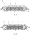
- FIGS. 1 and 2 show a device 1 for closing off the air intake of a motor vehicle.
- a closing device 1 is generally arranged on the front face of the motor vehicle and allows the control of an incoming air flow, in particular to heat exchangers such as radiators and/or evaporator-condensers.
- the closing device 1 also allows the incoming air flow to be directed in a desired direction, for example in order to direct it towards the heat exchangers.
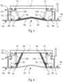
- This closing device 1 comprises a support frame 3 comprising a front face 3a (visible in Figure 1 ) ), intended to be exposed to the incoming air flow, and a rear face 3b (visible in Figure 2 ) opposite the front face 3a.
- the front face 3a is in particular intended to face an incoming air flow, for example by being oriented towards the front of the motor vehicle in the assembled state.
- the rear face 3b is intended to face the interior of the motor vehicle in the assembled state, for example by facing one or more heat exchangers.
- the support frame 3 comprises at least one through-orifice so that the incoming air flow passes through the closure device.
- Each through-orifice comprises a closure assembly 5 comprising at least two complementary closure flaps 50.
- the flaps 50 are each movable around a respective pivot axis 51 (visible in Figure 3 ) between a closed position, in which the through-orifice is closed by complementarity of the at least two flaps 50, and an open position the incoming air flow can pass through the through-orifice. More particularly, the flaps 50 open so as to project from the rear face 3b of the support frame 3 in the open position.
- the support frame 3 comprises a plurality, here six, of through orifices, each comprising its own closure assembly 5.
- the through holes are arranged edge to edge.
- the pivot axes 51 of the flaps 50 of a closure assembly 5 may more particularly be arranged in the same plane.
- at least two pivot axes 51 of flaps 50 may in particular be arranged on either side of the through-orifice.
- the pivot axes 51 of the flaps 50 may be arranged on the periphery of the through-orifice.
- the free edge of each flap 50, which is distal to the pivot axis 51, may cover a portion of a central zone of the through-orifice in the closure position.
- the support frame 3 may also comprise, within the at least one through-orifice, a frame 30 on which the edges of the flaps 50 rest in the closure position.
- the through hole has in the example illustrated in figures 1 to 3 a regular polygon shape, more particularly here a hexagon.
- the closure assemblies 5 then comprise a triangular flap 50 on each side of said through orifices.
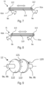
- the shutter device 1 further comprises a system for synchronous opening of the shutters 50 illustrated in Figure 4
- This opening system firstly comprises a suspended element 7 arranged on the rear face 3b of the support frame 3.
- suspended it is meant here that the element 7 is kept at a distance from the rear face 3b of the support frame 3 and is movable relative to the support frame 3.
- the suspended element 7 is more particularly openworked in line with the through openings so as to allow the circulation of an air flow.
- This suspended element 7 is in particular movable between a position close to the support frame 3 and a second position distant from the support frame 3.
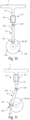
- the suspended element 7 is connected to each of the shutters 50 so that in the close position, the shutters 50 are in the closed position (see Figure 5 ) and that in remote position, the shutters 50 are in the open position (see Figure 6 ).
- the suspended element 7 may in particular perform a rectilinear translation perpendicular to the plane defined by the support frame 3.
- the shutter opening system 50 may in particular comprise at least one guide device 13 for guiding the suspended element 7 in translation between its position close to and its position distant from the support frame 3.
- the guide device 13 may in particular connect the suspended element 7 to the support frame 3 and be configured to give the suspended element 7 only a single degree of freedom of movement between its position close to and its position distant from the support frame 3.
- the shutter opening system may in particular comprise several guide devices 13 arranged regularly around the suspended element 7 in order to ensure uniform guidance of said suspended element 7.
- the guide rod 70 may, for example, be made of the same material as the suspended element 7. Another possibility is that the guide rod 70 is an added part fixed to the suspended element 7.
- the hollow of the hollow member 32 and the guide rod 70 may in particular have shapes that are complementary to each other. For example, they may both be cylindrical or both have a complementary polygonal section.
- connection between the suspended element 7 and a flap 50 may in particular comprise a connecting rod 130 fixed at a first end to the flap 50 by a pivot connection 52 and fixed at a second end to the suspended element 7 by another pivot connection 72.
- These pivot connections 52, 72 pivot more particularly around axes parallel to the pivot axis 51 of the flap 50.
- the use of a rigid connecting rod 130 and pivot connections 52, 72 allows direct transmission of forces and thus when the suspended element 7 translates towards its remote position ( Figure 6 ), it pulls the flaps 50 bringing them into the open position and thus clearing the through hole.
- the suspended element 7 translates towards its close position ( Figure 5 ) it pushes the flaps 50 bringing them into the position of closing the through hole.
- the suspended element 7 and the connecting rod 130 hold the flaps 50 in the closing position and prevent the latter from opening under the force of the wind or other arriving at the level of the front face 3a of the support frame 3.
- the synchronous opening system of the shutters 50 also comprises an actuating device configured to move the suspended element 7 from one position to another.
- the closing device 1 may comprise a linear actuator arranged on the support frame 3 and more particularly its rear face 3b and connected directly to the suspended element 7 in order to impart its translational movement to it.
- the actuating device may comprise at least one first shaft 9a arranged on the rear face 3b of the support frame 3.
- This first shaft 9a is arranged on a first side of the at least one closure assembly 5.
- This first shaft 9a is connected to an actuator 10 so as to set it in rotation.
- This rotation may for example be of the order of 90°.
- the actuating device has two first shafts 9a arranged on either side of an actuator 10 in a central position on the support frame 3. It is nevertheless entirely possible to imagine, for example, several actuators 10 arranged at the end of each first shaft 9a. Another possibility is to have only one first shaft 9a extending over the entire width of the support frame 3 and with a single actuator 10 connected to one of its ends.
- the actuating device further comprises at least one second shaft 9b arranged on the rear face 3b of the support frame 3 on a second side of the at least one closure assembly 5, opposite the first side.
- the first shafts 9a are connected to the second shaft 9b by at least one means 11 for transmitting the rotation of the first shaft 9a to the second shaft 9b.
- the actuating device comprises two second shafts 9b.
- Each second shaft 9b is connected to a first shaft 9a by a dedicated transmission means 11. It is also possible to imagine an embodiment in which several transmission means 11 connect a first 9a and a second 9b shaft.
- the multiplication of the transmission means 11 allows in particular a good transmission of the rotation and also makes it possible to distribute the forces in order to limit the deformation constraints on the shafts 9a, 9b.
- the transmission means 11 can in particular transmit the rotation of the first shaft 9a to the second shaft 9b both in a clockwise and counterclockwise direction.
- the means 11 for transmitting the rotation of a first shaft 9a to a second shaft 9b is preferably arranged so as to be concealed behind a structural element of the support frame 3.
- the transmission means 11 are arranged at one end of the first 9a and second 9b shafts behind the support frame 3. It is however entirely possible to imagine an embodiment in which the transmission means 11 pass between two through-holes or above a frame 30 of a through-hole. This thus allows the transmission means transmission 11 is not visible from the front face 3a of the support frame 3.
- the means 11 for transmitting the rotation of the first shaft 9a to the second shaft 9b may comprise a toothed belt connecting the first 9a and second 9b shafts.
- the means 11 for transmitting the rotation of the first shaft 9a to the second shaft 9b may comprise a pinion carried by each of the first 9a and second 9b shafts, said pinions being connected by a transmission chain.
- the means 11 for transmitting the rotation of the first shaft 9a to the second shaft 9b comprises a first lever arm 91a carried by the first shaft 9a and a second lever arm 91b carried by the second axis 9b.
- the ends of the first 91a and second 91b lever arms being connected to each other by a connecting rod 112.
- This connecting rod 112 comprises in particular pivot connections 112 with the first 941a and second 91b lever arms.
- the lever arms 91a, 91b may in particular come from the same material as their respective shaft 9a, 9b.
- the shaft 9a, 9b with its lever arms 91a, 91b may for example be produced by injection within a mold.
- the lever arms 91a, 92b may be in the form of discs concentric with the shaft 9a, 9b and comprising an offset axis or orifice in order to ensure the pivot connection with the connecting rod 112.
- the actuating device also comprises at least one means 12 for converting the rotation of the first 9a and second 9b shafts into translational movement of the suspended element 7.
- the actuating device comprises several conversion means 12 distributed regularly on the different shafts 9a, 9b. Having several conversion means 12 allows uniform pushing and pulling of the suspended element 7 and limits the torsional forces and limits the risks of jamming.
- the different conversion means 12 are also synchronous with each other so as to exert a uniform pushing or pulling on the suspended element 7.
- the means 12 for converting the rotation of the first 9a and second 9b shafts into translational movement of the suspended element 7 firstly comprises a crank 120 carried by one of the first 9a or second 9b shafts.
- crank 120 is meant here an axis 121 parallel to the axis of rotation of the first 9a or second 9b shaft and offset relative to it.
- the axis 121 and the first 9a or second 9b shaft are connected by at least one lever arm 122.
- the lever arm 122 is a disc concentric with the axis of rotation of the first 9a or second 9b shaft. The use of a disc as the lever arm 122 allows a better distribution of masses, particularly during rotation.
- the crank 120 comprises two lever arms 122. This makes it possible to release the axis of rotation of the first 9a or second shaft 9b while ensuring continuity in the rotation between two shaft portions 9a, 9b separated by the crank 120. It is nevertheless entirely possible to imagine an embodiment in which a “U”-shaped crank 120 similar to that of a crankshaft is used or comprising a lever arm in a form other than a disc.
- the plane connecting the axis 121 to the axis of rotation of the first 9a or second 9b shaft is the same for all the cranks 120 of the same shaft 9a, 9b.
- the cranks 120 of the first shaft 9a are arranged in a plane parallel to those of the second shaft 9b always in order to ensure good synchronicity.
- the means 12 for converting the rotation of the first 9a and second 9b shafts into translational movement of the suspended element 7 further comprises a connecting member connected at one of its ends to the structural element 7 and connected to the crank 120 at its opposite end.
- the connecting member may be a connecting rod 125 comprising an articulated connection with the crank 120 and an articulated connection 123 with the suspended element 7.
- the articulated connection between the connecting rod 125 and the crank 120 is more particularly a pivot connection around the axis 121 of said crank 120.
- the articulated connection 123 between the connecting rod 125 and the suspended element 7 may also be a pivot connection pivoting around an axis parallel to the axis of rotation of the shaft 9a, 9b. In the example illustrated in Figures 10 and 11 this articulated connection 123 is made at the end of the guide rod 70 of the suspended element 7. It is nevertheless entirely possible to imagine a variant not illustrated in which the articulated connection 123 is made elsewhere on the suspended element 7.
- the connecting member is a pivot/slide connection between the crank 120 and the end of the rod 70 of the suspended element 7.
- the end of the rod 70 comprises a slide 124 extending in a plane perpendicular to the axis of rotation of the shaft 9a, 9b in which the axis 121 of the crank 120 can slide and rotate.
- the rod 70 may be the same rod 70 of the suspended element 7 used for the guide device 13.
- the closing device 1 allows, due to the presence of the suspended element 7, a synchronous opening and closing of all the shutters 50 regardless of their arrangement on the support frame 3.
Landscapes
- Engineering & Computer Science (AREA)
- Chemical & Material Sciences (AREA)
- Combustion & Propulsion (AREA)
- Mechanical Engineering (AREA)
- Transportation (AREA)
- General Engineering & Computer Science (AREA)
- Air-Flow Control Members (AREA)
- Cooling, Air Intake And Gas Exhaust, And Fuel Tank Arrangements In Propulsion Units (AREA)
Description
- La présente invention concerne un dispositif d'obturation et plus précisément un dispositif d'obturation d'entrée d'air de face avant de véhicule automobile.
- Les faces avant de véhicules automobiles sont généralement composées de deux entrées d'air principales dites voie haute et voie basse, séparées par une poutre parechoc. Derrière cette poutre parechoc sont généralement placés les échangeurs de chaleur du véhicule automobile, comme par exemple celui utilisé pour la climatisation de l'habitacle et/ou encore celui utilisé pour le refroidissement du moteur
- Il est également connu de disposer, dans le trajet d'air passant par les entrées d'air principales, plus généralement la voie basse, un cadre support comportant une multiplicité de volets montés pivotants autour d'axes parallèles et propres à prendre une multiplicité de positions angulaires différentes, comprises entre une position d'ouverture et une position d'obturation, sous l'action de moyens de commande appropriés. Les différents volets comprennent généralement à une de leurs extrémités un bras de levier relié à une bielle commune. Cette bielle commune est entraînée en mouvement de translation par un actionneur et contrôle ainsi l'ouverture et la fermeture synchrone des volets.
- On obtient ainsi un dispositif d'obturation s'apparentant à une jalousie qui permet d'ajuster le débit d'air traversant les entrées d'airs et arrivant aux échangeurs de chaleur. Il est ainsi possible d'optimiser l'efficacité de ces échangeurs de chaleur en fonction des besoins en faisant varier la quantité d'air qu'ils reçoivent. De plus, à grande vitesse, les volets en position d'obturation permettent de diminuer le coefficient de traînée du véhicule et ainsi améliorent l'aérodynamisme dudit véhicule.
- Néanmoins, ce type de dispositif d'obturation peut ne pas être adapté notamment lorsque les volets ne sont pas disposés parallèlement les uns aux autres, par exemple dans une volonté esthétique de la part du constructeur. En effet, dans ce cas de figure, il est important d'avoir une synchronicité de l'ouverture et de la fermeture des volets ce que ne peut assurer une liaison à une bielle commune lorsque les volets ne s'ouvrent pas parallèlement les uns des autres
- Par ailleurs, d'autres exemples de réalisation de dispositifs d'obturation sont fournis par les documents
US10730384B1 WO2016/097589A1 . - Un des buts de la présente invention est donc de remédier au moins partiellement aux inconvénients de l'art antérieur en proposant un dispositif d'obturation amélioré et permettant un contrôle synchrone de l'ouverture et de la fermeture des volets quelle que soit leur disposition au sein du cadre support.
- La présente invention concerne donc un dispositif d'obturation d'entrée d'air de véhicule automobile, ledit dispositif d'obturation comportant un cadre support comportant une face avant, destinée à être exposée à un flux d'air entrant, et une face arrière opposée à la face avant, ledit cadre support comportant au moins un orifice traversant, chaque orifice traversant comportant un ensemble d'obturation comportant au moins deux volets complémentaires et mobiles chacun autour d'un axe de pivotement respectif entre une position d'obturation, dans laquelle l'orifice traversant est obturé par complémentarité des au moins deux volets, et une position d'ouverture, dans laquelle le flux d'air entrant peut traverser l'orifice traversant, les volets s'ouvrant de sorte à faire saillie de la face arrière du cadre support en position d'ouverture,
- le dispositif d'obturation comportant en outre un système d'ouverture synchrone des volets, caractérisé en ce que
- ledit système d'ouverture comportant :
- un élément suspendu disposé en face arrière du cadre support et mobile entre une position rapprochée du cadre support et une position éloignée du cadre support, ledit élément suspendu étant relié à chacun des volets de sorte qu'en position rapprochée, les volets sont en position d'obturation et qu'en position éloignée, les volets sont en position d'ouverture,
- un dispositif d'actionnement configuré pour déplacer l'élément suspendu entre la position rapprochée et la deuxième position éloignée.
- Selon un aspect de l'invention, les axes de pivotement des volets d'un ensemble d'obturation sont disposés dans un même plan.
- Selon un autre aspect de l'invention, au sein d'un même ensemble d'obturation au moins deux axes de pivotement de volets sont disposés de part et d'autre de l'orifice traversant.
- Selon un autre aspect de l'invention, au sein d'un même ensemble d'obturation, les axes de pivotement des volets sont disposés en périphérie de l'orifice traversant.
- Selon un autre aspect de l'invention, au sein d'un même ensemble d'obturation, le bord libre de chaque volet qui est distal à l'axe de pivotement, couvre une partie d'une zone centrale de l'orifice traversant en position d'obturation.
- Selon un autre aspect de l'invention, le système d'ouverture des volets comporte au moins un dispositif de guidage pour guider l'élément suspendu en translation entre sa position rapprochée et sa position éloignée du cadre support.
- Selon un autre aspect de l'invention, le dispositif de guidage comporte :
- un organe creux disposé sur le cadre support, le creux dudit organe s'étendant selon un axe parallèle au mouvement de l'élément suspendu, et
- une tige de guidage insérée dans l'organe creux de sorte à pouvoir coulisser dans ledit organe creux et dont une extrémité est reliée à l'élément suspendu.
- Selon un autre aspect de l'invention, la liaison entre l'élément suspendu et un volet comporte une bielle de liaison fixée à une première extrémité au volet par une liaison pivot et fixée à une deuxième extrémité à l'élément suspendu par une autre liaison pivot.
- Selon un autre aspect de l'invention, le dispositif d'actionnement comporte au moins un actionneur linéaire.
- Selon un autre aspect de l'invention, le dispositif d'actionnement comporte :
- au moins un premier arbre disposé sur la face arrière du cadre support sur un premier côté de l'au moins un ensemble d'obturation, ledit au moins un premier arbre étant relié à un actionneur de sorte à le mettre en rotation,
- au moins un deuxième arbre disposé sur la face arrière du cadre support sur un deuxième côté de l'au moins un ensemble d'obturation, opposé au premier côté,
- au moins un moyen de transmission de la rotation du premier arbre au deuxième arbre,
- au moins un moyen de conversion de la rotation des premier et deuxième arbres en mouvement de translation de l'élément suspendu.
- Selon un autre aspect de l'invention, le moyen de transmission de la rotation du premier arbre au deuxième arbre comporte un premier bras de levier porté par le premier arbre et un deuxième bras de levier porté par le deuxième axe, les extrémités des premier et deuxième bras de levier étant reliées l'une à l'autre par une bielle.
- Selon un autre aspect de l'invention, le moyen de transmission de la rotation du premier arbre au deuxième arbre comporte une courroie crantée reliant les premier et deuxième arbres.
- Selon un autre aspect de l'invention, le moyen de transmission de la rotation du premier arbre au deuxième arbre comporte un pignon porté par chacun des premier et deuxième arbres, lesdits pignons étant reliés par une chaîne de transmission.
- Selon un autre aspect de l'invention, le moyen de transmission de la rotation du premier arbre (9a) au deuxième arbre est disposé de sorte à être dissimulé derrière un élément de structure du cadre support.
- Selon un autre aspect de l'invention, le moyen de conversion de la rotation des premier et deuxième arbres en mouvement de translation de l'élément suspendu comporte :
- une manivelle portée par un des premier ou deuxième arbres,
- un organe de liaison reliée à une ses extrémités à l'élément suspendu et reliée à la manivelle à son extrémité opposée.
- Selon un autre aspect de l'invention, l'organe de liaison est une bielle comportant une liaison articulée avec la manivelle et une liaison articulée avec l'élément de structure.
- Selon un autre aspect de l'invention, l'organe de liaison est une liaison pivot-glissière entre la manivelle et l'extrémité d'une tige de l'élément suspendu, ladite extrémité de la tige comportant une glissière s'étendant dans un plan perpendiculaire à l'axe de rotation de l'arbre.
- Selon un autre aspect de l'invention, l'élément suspendu est ajouré à l'aplomb des ouvertures traversantes de sorte à permettre la circulation d'un flux d'air.
- Selon un autre aspect de l'invention, le cadre support comporte une pluralité d'orifices traversants en forme de polygone régulier, les ensembles d'obturation comportant un volet triangulaire par côté desdits orifices traversants.
- Selon un autre aspect de l'invention, le cadre support comporte, au sein de l'au moins un orifice traversant, une armature sur laquelle les bords des volets reposent en position d'obturation.
- D'autres caractéristiques et avantages de l'invention apparaîtront plus clairement à la lecture de la description suivante, donnée à titre d'exemple illustratif et non limitatif, et des dessins annexés parmi lesquels :
- [
Fig 1 ] lafigure 1 montre une représentation schématique en perspective de la face avant d'un dispositif d'obturation en position d'obturation, - [
Fig 2 ] lafigure 2 montre une représentation schématique en perspective de la face arrière d'un dispositif d'obturation en position d'obturation, - [
Fig 3 ] lafigure 3 montre une représentation schématique en perspective d'un ensemble d'obturation d'un orifice traversant du cadre support, - [
Fig 4 ] lafigure 4 montre une représentation schématique en perspective de la face arrière d'un dispositif d'obturation en position d'obturation avec un système d'ouverture synchrone des volets, - [
Fig 5 ] lafigure 5 montre une représentation schématique en coupe et vue de côté du système d'ouverture synchrone des volets avec les volets en position d'obturation, - [
Fig 6 ] lafigure 6 montre une représentation schématique en coupe et vue de côté du système d'ouverture synchrone des volets avec les volets en position d'ouverture, - [
Fig 7 ] lafigure 7 montre une représentation schématique en coupe et vue de côté d'un moyen de transmission de la rotation du premier arbre au deuxième arbre selon une première position, - [
Fig 8 ] lafigure 8 montre une représentation schématique en coupe et vue de côté d'un moyen de transmission de la rotation du premier arbre au deuxième arbre selon une deuxième position, - [
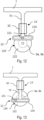
Fig 9 ] lafigure 9 montre une représentation schématique en perspective d'une manivelle d'un arbre, - [
Fig 10 ] lafigure 10 montre une représentation schématique en coupe et vue de côté d'un moyen de conversion dans une première position selon un premier mode de réalisation, - [
Fig 11 ] lafigure 11 montre une représentation schématique en coupe et vue de côté d'un moyen de conversion dans une deuxième position selon le premier mode de réalisation, - [
Fig 12 ] lafigure 12 montre une représentation schématique en coupe et vue de côté d'un moyen de conversion dans une première position selon un deuxième mode de réalisation, - [
Fig 13 ] lafigure 13 montre une représentation schématique en coupe et vue de côté d'un moyen de conversion dans une deuxième position selon le deuxième mode de réalisation. - Les éléments identiques sur les différentes figures, portent les mêmes références.
- Les réalisations suivantes sont des exemples. Bien que la description se réfère à un ou plusieurs modes de réalisation, ceci ne signifie pas nécessairement que chaque référence concerne le même mode de réalisation, ou que les caractéristiques s'appliquent seulement à un seul mode de réalisation. De simples caractéristiques de différents modes de réalisation peuvent également être combinées ou interchangées pour fournir d'autres réalisations.
- Dans la présente description on peut indexer certains éléments ou paramètres, comme par exemple premier élément ou deuxième élément ainsi que premier paramètre et deuxième paramètre ou encore premier critère et deuxième critère etc. Dans ce cas, il s'agit d'un simple indexage pour différencier et dénommer des éléments ou paramètres ou critères proches mais non identiques. Cette indexation n'implique pas une priorité d'un élément, paramètre ou critère par rapport à un autre et on peut aisément interchanger de telles dénominations sans sortir du cadre de la présente description. Cette indexation n'implique pas non plus un ordre dans le temps par exemple pour apprécier tels ou tels critères.
- Les
figures 1 et 2 montrent un dispositif d'obturation 1 d'entrée d'air de véhicule automobile. Un tel dispositif d'obturation 1 est généralement disposé en face avant du véhicule automobile et permet le contrôle d'un flux d'air entrant, notamment à destination d'échangeurs de chaleur tels que des radiateurs et/ou des évapo-condenseurs. Le dispositif d'obturation 1 permet également d'orienter le flux d'air entrant selon une direction souhaitée, par exemple afin de l'orienter vers les échangeurs de chaleurs. Ce dispositif d'obturation 1 comporte un cadre support 3 comportant une face avant 3a (visible enfigure 1 ) ), destinée à être exposée au flux d'air entrant, et une face arrière 3b (visible enfigure 2 ) opposée à la face avant 3a. La face avant 3a est notamment destinée à faire face à un flux d'air entrant, par exemple en étant orientée vers l'avant du véhicule automobile à l'état monté. La face arrière 3b est quant à elle destinée à faire face à l'intérieur du véhicule automobile à l'état monté, par exemple en faisant face à un ou plusieurs échangeurs de chaleur. - Le cadre support 3 comporte au moins un orifice traversant afin que le flux d'air entrant traverse le dispositif d'obturation. Chaque orifice traversant comportant un ensemble d'obturation 5 comportant au moins deux volets 50 d'obturation complémentaires. Les volets 50 sont mobiles chacun autour d'un axe de pivotement 51 respectif (visible en
figure 3 ) entre une position d'obturation, dans laquelle l'orifice traversant est obturé par complémentarité des au moins deux volets 50, et une position d'ouverture le flux d'air entrant peut traverser orifice traversant. Plus particulièrement, les volets 50 s'ouvrent de sorte à faire saillie de la face arrière 3b du cadre support 3 en position d'ouverture. - Dans l'exemple illustré aux
figures 1 et 2 , le cadre support 3 comporte une pluralité, ici six, d'orifices traversants, chacun comportant un ensemble d'obturation 5 propre. Sur lesfigures 1 et 2 , les orifices traversants sont disposés bords à bords. Il est cependant tout à fait possible d'imaginer des orifices traversants disposés distants sur le cadre support 3. - Comme le montre plus en détail la
figure 3 , les axes de pivotement 51 des volets 50 d'un ensemble d'obturation 5 peuvent être plus particulièrement disposés dans un même plan. Au sein d'un même ensemble d'obturation 5, au moins deux axes de pivotement 51 de volets 50 peuvent notamment être disposés de part et d'autre de l'orifice traversant. De plus, les axes de pivotement 51 des volets 50 peuvent être disposés en périphérie de l'orifice traversant. Le bord libre de chaque volet 50, qui est distal à l'axe de pivotement 51, peut couvrir quant à lui une partie d'une zone centrale de l'orifice traversant en position d'obturation. Le cadre support 3 peut également comporter, au sein de l'au moins un orifice traversant, une armature 30 sur laquelle les bords des volets 50 reposent en position d'obturation. - L'orifice traversant a dans l'exemple illustré aux
figures 1 à 3 une forme de polygone régulier, plus particulièrement ici un hexagone. Les ensembles d'obturation 5 comportent alors un volet 50 triangulaire par côté desdits orifices traversants. - Le dispositif d'obturation 1 comporte en outre un système d'ouverture synchrone des volets 50 illustré à la
figure 4 . Ce système d'ouverture comporte tout d'abord un élément suspendu 7 disposé en face arrière 3b du cadre support 3. Par suspendu, on entend ici que l'élément 7 est maintenu à distance de la face arrière 3b du cadre support 3 et est mobile par rapport au cadre support 3. L'élément suspendu 7 est plus particulièrement ajouré à l'aplomb des ouvertures traversantes de sorte à permettre la circulation d'un flux d'air. - Cet élément suspendu 7 est notamment mobile entre une position rapprochée du cadre support 3 et une deuxième position éloignée du cadre support 3. L'élément suspendu 7 est relié à chacun des volets 50 de sorte qu'en position rapprochée, les volets 50 sont en position d'obturation (voir
figure 5 ) et qu'en position éloignée, les volets 50 sont en position d'ouverture (voirfigure 6 ). - Afin de passer d'une position à une autre, l'élément suspendu 7 peut notamment effectuer une translation rectiligne perpendiculairement au plan défini par le cadre support 3. Afin d'assurer une translation rectiligne, le système d'ouverture des volets 50 peut notamment comporter au moins un dispositif de guidage 13 pour guider l'élément suspendu 7 en translation entre sa position rapprochée et sa position éloignée du cadre support 3. Le dispositif de guidage 13 peut notamment relier l'élément suspendu 7 au cadre support 3 et être configuré pour ne conférer à élément suspendu 7 qu'un seul degré de liberté de mouvement entre sa position rapprochée et sa position éloignée du cadre support 3. Le système d'ouverture des volets peut notamment comporter plusieurs dispositifs de guidage 13 disposés régulièrement autour de l'élément suspendu 7 afin d'assurer un guidage uniforme dudit élément suspendu 7.
- Ce dispositif de guidage 13 peut notamment comporter :
- un organe creux 32 disposé sur le cadre support 3, le creux dudit organe 32 s'étendant selon un axe parallèle au mouvement de l'élément suspendu 7, et
- une tige 70 de guidage insérée dans l'organe creux 32 de sorte à pouvoir coulisser dans ledit cylindre creux 32 et dont une extrémité est reliée à l'élément suspendu 7.
- La tige 70 de guidage peut par exemple venir de matière avec l'élément suspendu 7. Une autre possibilité est que la tige 70 de guidage soit une pièce rapportée et fixée à l'élément suspendu 7. Le creux de l'organe creux 32 ainsi que la tige 70 de guidage peuvent notamment avoir des formes complémentaires l'une par rapport à l'autre. Par exemple ils peuvent être tous les deux cylindriques ou bien avoir tous les deux une section polygonale complémentaire.
- Comme illustré aux
figures 5 et 6 , la liaison entre l'élément suspendu 7 et un volet 50 peut notamment comporter une bielle 130 de liaison fixée à une première extrémité au volet 50 par une liaison pivot 52 et fixée à une deuxième extrémité à l'élément suspendu 7 par une autre liaison pivot 72. Ces liaisons pivots 52, 72 pivotent plus particulièrement autour d'axes parallèles à l'axe de pivotement 51 du volet 50. L'utilisation d'une bielle 130 rigide et de liaisons pivots 52, 72 permet une transmission directe des forces et ainsi lorsque l'élément suspendu 7 translate vers sa position éloignée (figure 6 ), il tire les volets 50 les amenant en position d'ouverture et dégageant ainsi l'orifice traversant. Lorsque l'élément suspendu 7 translate vers sa position rapprochée (figure 5 ) il pousse les volets 50 les amenant en position d'obturation de l'orifice traversant. En position d'obturation des volets 50, l'élément suspendu 7 et la bielle 130 maintiennent les volets 50 en position d'obturation et empêchent ces derniers de s'ouvrir sous la force du vent ou autre arrivant au niveau de la face avant 3a du cadre support 3. - Le système d'ouverture synchrone des volets 50 comporte également un dispositif d'actionnement configuré pour déplacer l'élément suspendu 7 d'une position à une autre. Selon une première variante non illustrée, le dispositif d'obturation 1 peut comporter un actionneur linéaire disposé sur le cadre support 3 et plus particulièrement sa face arrière 3b et relié directement à l'élément suspendu 7 afin de lui imprimer son mouvement de translation.
- Selon une deuxième variante illustrée à la
figure 4 , le dispositif d'actionnement peut comporter au moins un premier arbre 9a disposé sur la face arrière 3b du cadre support 3. Ce premier arbre 9a est disposé sur un premier côté de l'au moins un ensemble d'obturation 5. Ce premier arbre 9a est relié à un actionneur 10 de sorte à le mettre en rotation. Cette rotation peut par exemple être de l'ordre de 90°. Dans l'exemple illustré à lafigure 4 , le dispositif d'actionnement dispose de deux premiers arbres 9a disposés de part et d'autre d'un actionneur 10 en position centrale sur le cadre support 3. Il est néanmoins tout à fait possible d'imaginer par exemple plusieurs actionneurs 10 disposés à l'extrémité de chaque premier arbre 9a. Une autre possibilité est de n'avoir qu'un seul premier arbre 9a s'étendant sur toute la largeur du cadre support 3 et avec un unique actionneur 10 connecté à une de ses extrémités. - Le dispositif d'actionnement comporte en outre au moins un deuxième arbre 9b disposé sur la face arrière 3b du cadre support 3 sur un deuxième côté de l'au moins un ensemble d'obturation 5, opposé au premier côté. Les premiers arbres 9a sont reliés aux deuxième arbre 9b par au moins un moyen de transmission 11 de la rotation du premier arbre 9a au deuxième arbre 9b. Dans l'exemple illustré à la
figure 4 , le dispositif d'actionnement comporte deux deuxièmes arbres 9b. Chaque deuxième arbre 9b étant relié à un premier arbre 9a par un moyen de transmission 11 dédié. Il est possible également d'imaginer un mode de réalisation dans lequel plusieurs moyens de transmission 11 relient un premier 9a et un deuxième 9b arbre. La multiplication des moyens de transmission 11 permet notamment une bonne transmission de la rotation et permet également de répartir les forces afin de limiter les contraintes de déformations sur les arbres 9a, 9b. Le moyen de transmission 11 peut notamment transmettre la rotation du premier arbre 9a au deuxième arbre 9b aussi bien dans un sens horaire qu'anti-horaire. - Le moyen de transmission 11 de la rotation d'un premier arbre 9a à un deuxième arbre 9b est de préférence disposé de sorte à être dissimulé derrière un élément de structure du cadre support 3. Dans l'exemple de la
figure 4 , les moyens de transmission 11 sont disposés à une extrémité des premier 9a et deuxième 9b arbres derrière le cadre support 3. Il est cependant tout à fait possible d'imaginer un mode de réalisation dans lequel les moyens de transmission 11 passent entre deux orifices traversants ou bien au-dessus d'une armature 30 d'un orifice traversant. Cela permet ainsi que le moyen de transmission 11 ne soit pas visible depuis la face avant 3a du cadre support 3. - Selon une première variante non illustrée, le moyen de transmission 11 de la rotation du premier arbre 9a au deuxième arbre 9b peut comporter une courroie crantée reliant les premier 9a et deuxième 9b arbres. Selon une deuxième variante également non illustrée, le moyen de transmission 11 de la rotation du premier arbre 9a au deuxième arbre 9b peut comporter un pignon porté par chacun des premier 9a et deuxième 9b arbres, lesdits pignons étant reliés par une chaîne de transmission.
- Selon une troisième variante illustrée aux
figures 7 et 8 , le moyen de transmission 11 de la rotation du premier arbre 9a au deuxième arbre 9b comporte un premier bras de levier 91a porté par le premier arbre 9a et un deuxième bras de levier 91b porté par le deuxième axe 9b. Les extrémités des premier 91a et deuxième 91b bras de levier étant reliées l'une à l'autre par une bielle 112. Cette bielle 112 comporte notamment des liaisons pivots 112 avec les premier 941a et deuxième 91b bras de levier. Les bras de levier 91a, 91b peuvent notamment venir de matière avec leur arbre 9a, 9b respectif. L'arbre 9a, 9b avec ses bras de levier 91a, 91b peuvent par exemple être réalisés par injection au sein d'un moule. Selon un mode de réalisation non représenté, les bras de levier 91a, 92b peuvent se présenter sous la forme de disques concentriques avec l'arbre 9a, 9b et comportant un axe ou un orifice déporté afin d'assurer la liaison pivot avec la bielle 112. - En référence à la
figure 4 , le dispositif d'actionnement comporte également au moins un moyen de conversion 12 de la rotation des premier 9a et deuxième 9b arbres en mouvement de translation de l'élément suspendu 7. Dans l'exemple illustré à lafigure 4 , le dispositif d'actionnement comporte plusieurs moyens de conversion 12 répartis régulièrement sur les différents arbres 9a, 9b. Le fait d'avoir plusieurs moyens de conversion 12 permet une poussée et une traction uniforme de l'élément suspendu 7 et limite les forces de torsions et limite les risques de coincement. Les différents moyens de conversion 12 sont également synchrones les uns avec les autres de sorte à exercer une poussée ou une traction uniforme à l'élément suspendu 7. - Ce moyen de conversion 12 est décrit plus en détail aux
figures 9 à 13 . Le moyen de conversion 12 de la rotation des premier 9a et deuxième 9b arbres en mouvement de translation de l'élément suspendu 7 comporte tout d'abord une manivelle 120 portée par un des premier 9a ou deuxième 9b arbres. Par manivelle 120, on entend ici un axe 121 parallèle à l'axe de rotation du premier 9a ou deuxième 9b arbre et décalé par rapport à celui-ci. L'axe 121 et le premier 9a ou deuxième 9b arbre sont reliés par au moins un bras de levier 122. Dans l'exemple illustré à lafigure 9 , le bras de levier 122 est un disque concentrique avec l'axe de rotation du premier 9a ou deuxième 9b arbre. L'utilisation d'un disque comme bras de levier 122 permet une meilleure répartition des masses notamment lors de la rotation. Toujours selon l'exemple illustré à lafigure 9 , la manivelle 120 comporte deux bras de levier 122. Cela permet de dégager l'axe de rotation du premier 9a ou deuxième arbre 9b tout en assurant une continuité dans la rotation entre deux portions d'arbre 9a, 9b séparés par la manivelle 120. Il est néanmoins tout à fait possible d'imaginer un mode de réalisation dans lequel une manivelle 120 en « U » similaire à celle d'un vilebrequin est utilisée ou alors comportant un bras de levier sous une autre forme qu'un disque. - Afin d'assurer une conversion et une transmission synchrone à l'élément suspendu 7, le plan reliant l'axe 121 à l'axe de rotation du premier 9a ou deuxième 9b arbre est le même pour toutes les manivelles 120 d'un même arbre 9a, 9b. Les manivelles 120 du premier arbre 9a sont disposées selon un plan parallèle à celles du deuxième arbre 9b toujours afin d'assurer une bonne synchronicité.
- Le moyen de conversion 12 de la rotation des premier 9a et deuxième 9b arbres en mouvement de translation de l'élément suspendu 7 comporte en outre un organe de liaison relié à une ses extrémités à l'élément de structure 7 et reliée à la manivelle 120 à son extrémité opposée.
- Selon un premier mode de réalisation illustré aux
figures 10 et 11 , l'organe de liaison peut être une bielle 125 comportant une liaison articulée avec la manivelle 120 et une liaison articulée 123 avec l'élément suspendu 7. La liaison articulée entre la bielle 125 et la manivelle 120 est plus particulièrement une liaison pivot autour de l'axe 121 de ladite manivelle 120. La liaison articulée 123 entre la bielle 125 et l'élément suspendu 7 peut être également une liaison pivot pivotant autour d'un axe parallèle à l'axe de rotation de l'arbre 9a, 9b. Dans l'exemple illustré auxfigures 10 et 11 cette liaison articulée 123 est réalisée à l'extrémité de la tige de guidage 70 de l'élément suspendu 7. Il est néanmoins tout à fait possible d'imaginer une variante non illustrée dans laquelle la liaison articulée 123 est réalisée ailleurs sur l'élément suspendu 7. - Selon un deuxième mode de réalisation illustré aux
figures 12 et 13 , l'organe de liaison est une liaison pivot/glissière entre la manivelle 120 et l'extrémité de la tige 70 de l'élément suspendu 7. L'extrémité de la tige 70 comporte une glissière 124 s'étendant dans un plan perpendiculaire à l'axe de rotation de l'arbre 9a, 9b dans laquelle l'axe 121 de la manivelle 120 peut coulisser et tourner. Préférentiellement, la tige 70 peut être la même tige 70 de l'élément suspendu 7 utilisée pour le dispositif de guidage 13. - Ainsi, on voit bien que le dispositif d'obturation 1 permet de par la présence de l'élément suspendu 7 une ouverture et une fermeture synchrone de tous les volets 50 quel que soit leur disposition sur le cadre support 3.
Claims (10)
- Dispositif d'obturation (1) d'entrée d'air de véhicule automobile, ledit dispositif d'obturation (1) comportant un cadre support (3) comportant une face avant (3a), destinée à être exposée à un flux d'air entrant, et une face arrière (3b) opposée à la face avant (3a), ledit cadre support (3) comportant au moins un orifice traversant, chaque orifice traversant comportant un ensemble d'obturation (5) comportant au moins deux volets (50) complémentaires et mobiles chacun autour d'un axe de pivotement (51) respectif entre une position d'obturation, dans laquelle l'orifice traversant est obturé par complémentarité des au moins deux volets (50), et une position d'ouverture, dans laquelle le flux d'air entrant peut traverser l'orifice traversant, les volets (50) s'ouvrant de sorte à faire saillie de la face arrière (3b) du cadre support (3) en position d'ouverture, le dispositif d'obturation (1) comportant en outre un système d'ouverture synchrone des volets (50), caractérisé en ce que ledit système d'ouverture comportant :- un élément suspendu (7) disposé en face arrière (3b) du cadre support (3) et mobile entre une position rapprochée du cadre support (3) et une position éloignée du cadre support (3), ledit élément suspendu (7) étant relié à chacun des volets (50) de sorte qu'en position rapprochée, les volets (50) sont en position d'obturation et qu'en position éloignée, les volets (50) sont en position d'ouverture,- un dispositif d'actionnement configuré pour déplacer l'élément suspendu (7) entre la position rapprochée et la deuxième position éloignée.
- Dispositif d'obturation (1) selon la revendication 1, caractérisé en ce que le système d'ouverture des volets (50) comporte au moins un dispositif de guidage (13) pour guider l'élément suspendu (7) en translation entre sa position rapprochée et sa position éloignée du cadre support (3).
- Dispositif d'obturation (1) selon la revendication précédente, caractérisé en ce que le dispositif de guidage (13) comporte :- un organe creux (32) disposé sur le cadre support (3), le creux dudit organe (32) s'étendant selon un axe parallèle au mouvement de l'élément suspendu (7), et- une tige (70) de guidage insérée dans l'organe creux (32) de sorte à pouvoir coulisser dans ledit organe creux (32) et dont une extrémité est reliée à l'élément suspendu (7).
- Dispositif d'obturation (1) selon l'une quelconque des revendications précédentes, caractérisé en ce que la liaison entre l'élément suspendu (7) et un volet (50) comporte une bielle (130) de liaison fixée à une première extrémité au volet (50) par une liaison pivot (52) et fixée à une deuxième extrémité à l'élément suspendu (7) par une autre liaison pivot (72).
- Dispositif d'obturation (1) selon l'une quelconque des revendications 1 à 4, caractérisé en ce que le dispositif d'actionnement comporte :- au moins un premier arbre (9a) disposé sur la face arrière (3b) du cadre support (3) sur un premier côté de l'au moins un ensemble d'obturation (5), ledit au moins un premier arbre (9a) étant relié à un actionneur (10) de sorte à le mettre en rotation,- au moins un deuxième arbre (9b) disposé sur la face arrière (3b) du cadre support (3) sur un deuxième côté de l'au moins un ensemble d'obturation (5), opposé au premier côté,- au moins un moyen de transmission (11) de la rotation du premier arbre (9a) au deuxième arbre (9b),- au moins un moyen de conversion (12) de la rotation des premier (9a) et deuxième (9b) arbres en mouvement de translation de l'élément suspendu (7).
- Dispositif d'obturation (1) selon la revendication 5, caractérisé en ce que le moyen de transmission (11) de la rotation du premier arbre (9a) au deuxième arbre (9b) comporte un premier bras de levier (91a) porté par le premier arbre (9a) et un deuxième bras de levier (91b) porté par le deuxième axe (9b), les extrémités des premier (91a) et deuxième (91b) bras de levier étant reliées l'une à l'autre par une bielle (112).
- Dispositif d'obturation (1) selon l'une quelconque des revendications 5 ou 6, caractérisé en ce que le moyen de conversion (12) de la rotation des premier (9a) et deuxième (9b) arbres en mouvement de translation de l'élément suspendu (7) comporte :- une manivelle (120) portée par un des premier (9a) ou deuxième (9b) arbres,- un organe de liaison reliée à une ses extrémités à l'élément suspendu (7) et reliée à la manivelle (120) à son extrémité opposée.
- Dispositif d'obturation (1) selon la revendication 7, caractérisé en ce que l'organe de liaison est une bielle (125) comportant une liaison articulée avec la manivelle (120) et une liaison articulée (123) avec l'élément de structure (7).
- Dispositif d'obturation (1) selon la revendication 7 en combinaison avec la revendication 3, caractérisé en ce que l'organe de liaison est une liaison pivot-glissière entre la manivelle (120) et l'extrémité d'une tige (70) de l'élément suspendu (7), ladite extrémité de la tige (70) comportant une glissière (124) s'étendant dans un plan perpendiculaire à l'axe de rotation de l'arbre (9a, 9b).
- Dispositif d'obturation (1) selon l'une quelconque des revendications précédentes, caractérisé en ce que le cadre support (3) comporte une pluralité d'orifices traversants en forme de polygone régulier, les ensembles d'obturation (5) comportant un volet (50) triangulaire par côté desdits orifices traversants.
Applications Claiming Priority (2)
| Application Number | Priority Date | Filing Date | Title |
|---|---|---|---|
| FR2104227A FR3122124B1 (fr) | 2021-04-22 | 2021-04-22 | dispositif d’obturation d’entrée d’air de face avant de véhicule automobile |
| PCT/EP2022/060467 WO2022223649A1 (fr) | 2021-04-22 | 2022-04-20 | Dispositif d'obturation d'entree d'air de face avant de vehicule automobile |
Publications (2)
| Publication Number | Publication Date |
|---|---|
| EP4326573A1 EP4326573A1 (fr) | 2024-02-28 |
| EP4326573B1 true EP4326573B1 (fr) | 2025-04-30 |
Family
ID=77021431
Family Applications (1)
| Application Number | Title | Priority Date | Filing Date |
|---|---|---|---|
| EP22723673.4A Active EP4326573B1 (fr) | 2021-04-22 | 2022-04-20 | Dispositif d'obturation d'entree d'air de face avant de vehicule automobile |
Country Status (6)
| Country | Link |
|---|---|
| US (1) | US20250269713A1 (fr) |
| EP (1) | EP4326573B1 (fr) |
| KR (1) | KR102838501B1 (fr) |
| CN (1) | CN117177874A (fr) |
| FR (1) | FR3122124B1 (fr) |
| WO (1) | WO2022223649A1 (fr) |
Families Citing this family (6)
| Publication number | Priority date | Publication date | Assignee | Title |
|---|---|---|---|---|
| CN114801708A (zh) * | 2022-03-28 | 2022-07-29 | 武汉路特斯汽车有限公司 | 一种主动进气格栅及车辆 |
| KR20240054721A (ko) * | 2022-10-19 | 2024-04-26 | 현대자동차주식회사 | 가변 그릴 장치 |
| FR3147542A1 (fr) * | 2023-04-07 | 2024-10-11 | Renault S.A.S | Calandre de véhicule automobile à débit d’air modulable |
| FR3154949A1 (fr) * | 2023-11-06 | 2025-05-09 | Valeo Systemes Thermiques | Module d’obturation d’entrée d’air de face avant de véhicule automobile et véhicule automobile comportant le module d’obturation d’entrée d’air. |
| FR3156075A1 (fr) * | 2023-11-30 | 2025-06-06 | Renault S.A.S | Système de volets pilotes pour vehicule |
| FR3162172A1 (fr) * | 2024-05-17 | 2025-11-21 | Renault S.A.S | Calandre de radiateur avec volets mobiles et procede de fonctionnement correspondant |
Citations (3)
| Publication number | Priority date | Publication date | Assignee | Title |
|---|---|---|---|---|
| DE102014103667A1 (de) * | 2013-03-28 | 2014-10-02 | Fuji Jukogyo Kabushiki Kaisha | Variable Leitungsvorrichtung für ein Fahrzeug |
| US20170144710A1 (en) * | 2015-11-24 | 2017-05-25 | Srg Global Inc. | Active grille shutter system with integrated radar |
| WO2019205650A1 (fr) * | 2018-04-23 | 2019-10-31 | Yanfeng Plastic Omnium Automotive Exterior Systems Co., Ltd. | Structure de liaison de lame pour grille de pare-chocs |
Family Cites Families (17)
| Publication number | Priority date | Publication date | Assignee | Title |
|---|---|---|---|---|
| DE10306158B4 (de) * | 2003-02-14 | 2016-12-15 | Bayerische Motoren Werke Aktiengesellschaft | Vorrichtung zur Einstellung der Kühlluftzuströmung zu einem Motorraum eines Kraftfahrzeuges, sowie Kraftfahrzeug mit einer solchen Einrichtung |
| KR100717905B1 (ko) * | 2006-08-25 | 2007-05-14 | (주)탑앤메디컬 | 다리의 혈행촉진 구동장치 |
| CA2974627C (fr) * | 2009-07-21 | 2018-12-04 | Magna International Inc. | Support de volet de compartiment de vehicule a conduit integre |
| KR101090824B1 (ko) * | 2009-09-15 | 2011-12-08 | 주식회사 에스에이치비 | 자동차용 에어플랩 개폐장치 |
| US8550887B2 (en) * | 2009-09-18 | 2013-10-08 | Lacks Enterprises, Inc. | Vehicle grill with moveable louvers |
| DE102010032085A1 (de) * | 2010-07-23 | 2011-03-17 | Daimler Ag | Kühlergrill für einen Kraftwagen |
| US20130068403A1 (en) * | 2011-09-21 | 2013-03-21 | Srg Global Inc. | Grille Shutter Seal |
| DE102012000173A1 (de) * | 2012-01-07 | 2013-07-11 | Hbpo Gmbh | Luftklappenanordnung |
| FR3029858B1 (fr) * | 2014-12-16 | 2017-02-24 | Electricfil Automotive | Dispositif de commande de volets par un actionneur lineaire |
| JP6155249B2 (ja) * | 2014-12-26 | 2017-06-28 | 株式会社ファルテック | グリルシャッタモジュール |
| FR3037869B1 (fr) * | 2015-06-26 | 2018-12-07 | Valeo Systemes Thermiques | Dispositif d'obturation d'une entree d'air et module de face avant associe |
| FR3052712B1 (fr) * | 2016-06-16 | 2018-07-06 | Peugeot Citroen Automobiles Sa | Dispositif de regulation d’un flux d’air circulant au travers d’une ouverture menagee dans un pare-chocs de vehicule automobile |
| CN206155141U (zh) * | 2016-09-29 | 2017-05-10 | 长城汽车股份有限公司 | 格栅总成及车辆 |
| US10183573B1 (en) * | 2017-07-18 | 2019-01-22 | Ford Global Technologies, Llc | Vehicle grille flow control assembly and method |
| US10730384B1 (en) * | 2019-04-03 | 2020-08-04 | Ford Global Technologies, Llc | Vehicle air flow shutter control assembly and method |
| KR102789603B1 (ko) * | 2020-09-11 | 2025-04-01 | 현대모비스 주식회사 | 차량용 액티브 에어 플랩 장치 |
| WO2022161621A1 (fr) * | 2021-01-29 | 2022-08-04 | Lotus Tech Innovation Centre Gmbh | Volet aérodynamique actif pour véhicule automobile |
-
2021
- 2021-04-22 FR FR2104227A patent/FR3122124B1/fr active Active
-
2022
- 2022-04-20 KR KR1020237033902A patent/KR102838501B1/ko active Active
- 2022-04-20 US US18/556,129 patent/US20250269713A1/en active Pending
- 2022-04-20 WO PCT/EP2022/060467 patent/WO2022223649A1/fr not_active Ceased
- 2022-04-20 EP EP22723673.4A patent/EP4326573B1/fr active Active
- 2022-04-20 CN CN202280028242.4A patent/CN117177874A/zh active Pending
Patent Citations (3)
| Publication number | Priority date | Publication date | Assignee | Title |
|---|---|---|---|---|
| DE102014103667A1 (de) * | 2013-03-28 | 2014-10-02 | Fuji Jukogyo Kabushiki Kaisha | Variable Leitungsvorrichtung für ein Fahrzeug |
| US20170144710A1 (en) * | 2015-11-24 | 2017-05-25 | Srg Global Inc. | Active grille shutter system with integrated radar |
| WO2019205650A1 (fr) * | 2018-04-23 | 2019-10-31 | Yanfeng Plastic Omnium Automotive Exterior Systems Co., Ltd. | Structure de liaison de lame pour grille de pare-chocs |
Also Published As
| Publication number | Publication date |
|---|---|
| US20250269713A1 (en) | 2025-08-28 |
| CN117177874A (zh) | 2023-12-05 |
| WO2022223649A1 (fr) | 2022-10-27 |
| KR20230154062A (ko) | 2023-11-07 |
| FR3122124B1 (fr) | 2025-11-21 |
| FR3122124A1 (fr) | 2022-10-28 |
| EP4326573A1 (fr) | 2024-02-28 |
| KR102838501B1 (ko) | 2025-07-24 |
Similar Documents
| Publication | Publication Date | Title |
|---|---|---|
| EP4326573B1 (fr) | Dispositif d'obturation d'entree d'air de face avant de vehicule automobile | |
| EP3411213B1 (fr) | Procédé de fabrication de volet de dispositif d'obturation de face avant et volet de dispositif d'obturation d'une entrée d'air de face avant | |
| EP3722585B1 (fr) | Turboreacteur double flux comportant une serie de lames rotatives pour obturer la veine du flux secondaire | |
| EP1457660A1 (fr) | Dispositif de fermeture et de verrouillage des obturateurs d'un inverseur de poussée | |
| WO2014001430A1 (fr) | Dispositif d'obturation d'entrée d'air de face avant de véhicule automobile | |
| CA2837612A1 (fr) | Ensemble d'actionnement pour inverseur de poussee pour moteur d'aeronef | |
| EP3845754A1 (fr) | Turboréacteur double flux comportant un système d'obturation de la veine du flux secondaire comportant un voile | |
| EP3715613A1 (fr) | Turboreacteur double flux comportant une serie de lames rotatives pour obturer la veine du flux secondaire | |
| FR3068304B1 (fr) | Dispositif d'obturation d'entree d'air de face avant de vehicule automobile | |
| FR3037283B1 (fr) | Dispositif d'obturation d'entree d'air de face avant de vehicule automobile | |
| EP3571080B1 (fr) | Dispositif d'obturation d'entree d'air de face avant de vehicule automobile et procede de fabrication | |
| EP3411256B1 (fr) | Dispositif d'obturation d'entrée d'air de face avant de véhicule automobile | |
| FR3066565A1 (fr) | Dispositif de liaison actionneur-levier pour dispositif d'obturation de face avant de vehicule automobile, et dispositif d'obturation de face avant associe | |
| EP4334152B1 (fr) | Volet extrude pour dispositif d'obturation d'entree d'air de face avant de vehicule automobile | |
| EP3538391A1 (fr) | Dispositif d'obturation pour entree d'air de face avant de vehicule automobile | |
| EP3576970A1 (fr) | Dispositif d'obturation d'entree d'air de face avant de vehicule automobile | |
| FR3061876A1 (fr) | Dispositif d’obturation d’entree d’air de face avant de vehicule automobile et procede de fabrication | |
| WO2025098971A1 (fr) | Module d'obturation d'entrée d'air de face avant de véhicule automobile et véhicule automobile comportant le module d'obturation d'entrée d'air | |
| FR3068921B1 (fr) | Dispositif de liaison actionneur-levier pour dispositif d'obturation de face avant de vehicule automobile, et dispositif d'obturation de face avant associe | |
| EP3524524B1 (fr) | Bouche de prélèvement d'air dynamique, dispositif de contrôle environnemental, moteur et véhicule équipés d'une telle bouche | |
| FR3061878A1 (fr) | Dispositif d’obturation d’entree d’air de face avant de vehicule automobile | |
| EP4334153A1 (fr) | Volet extrude pour dispositif d'obturation d'entree d'air de face avant de vehicule automobile | |
| FR3163436A1 (fr) | Dispositif d’obturation pour entrée d’air d’un véhicule | |
| WO2022171524A1 (fr) | Dispositif d'obturation de véhicule automobile | |
| FR3076495A1 (fr) | Dispositif d'obturation d'entree d'air de face avant de vehicule automobile |
Legal Events
| Date | Code | Title | Description |
|---|---|---|---|
| STAA | Information on the status of an ep patent application or granted ep patent |
Free format text: STATUS: UNKNOWN |
|
| STAA | Information on the status of an ep patent application or granted ep patent |
Free format text: STATUS: THE INTERNATIONAL PUBLICATION HAS BEEN MADE |
|
| PUAI | Public reference made under article 153(3) epc to a published international application that has entered the european phase |
Free format text: ORIGINAL CODE: 0009012 |
|
| STAA | Information on the status of an ep patent application or granted ep patent |
Free format text: STATUS: REQUEST FOR EXAMINATION WAS MADE |
|
| 17P | Request for examination filed |
Effective date: 20231011 |
|
| AK | Designated contracting states |
Kind code of ref document: A1 Designated state(s): AL AT BE BG CH CY CZ DE DK EE ES FI FR GB GR HR HU IE IS IT LI LT LU LV MC MK MT NL NO PL PT RO RS SE SI SK SM TR |
|
| DAV | Request for validation of the european patent (deleted) | ||
| DAX | Request for extension of the european patent (deleted) | ||
| STAA | Information on the status of an ep patent application or granted ep patent |
Free format text: STATUS: EXAMINATION IS IN PROGRESS |
|
| 17Q | First examination report despatched |
Effective date: 20240923 |
|
| GRAP | Despatch of communication of intention to grant a patent |
Free format text: ORIGINAL CODE: EPIDOSNIGR1 |
|
| STAA | Information on the status of an ep patent application or granted ep patent |
Free format text: STATUS: GRANT OF PATENT IS INTENDED |
|
| INTG | Intention to grant announced |
Effective date: 20250124 |
|
| GRAS | Grant fee paid |
Free format text: ORIGINAL CODE: EPIDOSNIGR3 |
|
| GRAA | (expected) grant |
Free format text: ORIGINAL CODE: 0009210 |
|
| STAA | Information on the status of an ep patent application or granted ep patent |
Free format text: STATUS: THE PATENT HAS BEEN GRANTED |
|
| AK | Designated contracting states |
Kind code of ref document: B1 Designated state(s): AL AT BE BG CH CY CZ DE DK EE ES FI FR GB GR HR HU IE IS IT LI LT LU LV MC MK MT NL NO PL PT RO RS SE SI SK SM TR |
|
| REG | Reference to a national code |
Ref country code: CH Ref legal event code: EP Ref country code: GB Ref legal event code: FG4D Free format text: NOT ENGLISH |
|
| REG | Reference to a national code |
Ref country code: DE Ref legal event code: R096 Ref document number: 602022013923 Country of ref document: DE |
|
| REG | Reference to a national code |
Ref country code: IE Ref legal event code: FG4D Free format text: LANGUAGE OF EP DOCUMENT: FRENCH |
|
| REG | Reference to a national code |
Ref country code: NL Ref legal event code: MP Effective date: 20250430 |
|
| REG | Reference to a national code |
Ref country code: AT Ref legal event code: MK05 Ref document number: 1789734 Country of ref document: AT Kind code of ref document: T Effective date: 20250430 |
|
| PG25 | Lapsed in a contracting state [announced via postgrant information from national office to epo] |
Ref country code: PT Free format text: LAPSE BECAUSE OF FAILURE TO SUBMIT A TRANSLATION OF THE DESCRIPTION OR TO PAY THE FEE WITHIN THE PRESCRIBED TIME-LIMIT Effective date: 20250901 Ref country code: FI Free format text: LAPSE BECAUSE OF FAILURE TO SUBMIT A TRANSLATION OF THE DESCRIPTION OR TO PAY THE FEE WITHIN THE PRESCRIBED TIME-LIMIT Effective date: 20250430 Ref country code: ES Free format text: LAPSE BECAUSE OF FAILURE TO SUBMIT A TRANSLATION OF THE DESCRIPTION OR TO PAY THE FEE WITHIN THE PRESCRIBED TIME-LIMIT Effective date: 20250430 |
|
| REG | Reference to a national code |
Ref country code: LT Ref legal event code: MG9D |
|
| PG25 | Lapsed in a contracting state [announced via postgrant information from national office to epo] |
Ref country code: GR Free format text: LAPSE BECAUSE OF FAILURE TO SUBMIT A TRANSLATION OF THE DESCRIPTION OR TO PAY THE FEE WITHIN THE PRESCRIBED TIME-LIMIT Effective date: 20250731 Ref country code: NO Free format text: LAPSE BECAUSE OF FAILURE TO SUBMIT A TRANSLATION OF THE DESCRIPTION OR TO PAY THE FEE WITHIN THE PRESCRIBED TIME-LIMIT Effective date: 20250730 |
|
| PG25 | Lapsed in a contracting state [announced via postgrant information from national office to epo] |
Ref country code: PL Free format text: LAPSE BECAUSE OF FAILURE TO SUBMIT A TRANSLATION OF THE DESCRIPTION OR TO PAY THE FEE WITHIN THE PRESCRIBED TIME-LIMIT Effective date: 20250430 Ref country code: NL Free format text: LAPSE BECAUSE OF FAILURE TO SUBMIT A TRANSLATION OF THE DESCRIPTION OR TO PAY THE FEE WITHIN THE PRESCRIBED TIME-LIMIT Effective date: 20250430 |
|
| PG25 | Lapsed in a contracting state [announced via postgrant information from national office to epo] |
Ref country code: BG Free format text: LAPSE BECAUSE OF FAILURE TO SUBMIT A TRANSLATION OF THE DESCRIPTION OR TO PAY THE FEE WITHIN THE PRESCRIBED TIME-LIMIT Effective date: 20250430 |
|
| PG25 | Lapsed in a contracting state [announced via postgrant information from national office to epo] |
Ref country code: HR Free format text: LAPSE BECAUSE OF FAILURE TO SUBMIT A TRANSLATION OF THE DESCRIPTION OR TO PAY THE FEE WITHIN THE PRESCRIBED TIME-LIMIT Effective date: 20250430 |
|
| PG25 | Lapsed in a contracting state [announced via postgrant information from national office to epo] |
Ref country code: AT Free format text: LAPSE BECAUSE OF FAILURE TO SUBMIT A TRANSLATION OF THE DESCRIPTION OR TO PAY THE FEE WITHIN THE PRESCRIBED TIME-LIMIT Effective date: 20250430 |
|
| PG25 | Lapsed in a contracting state [announced via postgrant information from national office to epo] |
Ref country code: RS Free format text: LAPSE BECAUSE OF FAILURE TO SUBMIT A TRANSLATION OF THE DESCRIPTION OR TO PAY THE FEE WITHIN THE PRESCRIBED TIME-LIMIT Effective date: 20250731 |
|
| PG25 | Lapsed in a contracting state [announced via postgrant information from national office to epo] |
Ref country code: IS Free format text: LAPSE BECAUSE OF FAILURE TO SUBMIT A TRANSLATION OF THE DESCRIPTION OR TO PAY THE FEE WITHIN THE PRESCRIBED TIME-LIMIT Effective date: 20250830 |
|
| PG25 | Lapsed in a contracting state [announced via postgrant information from national office to epo] |
Ref country code: LV Free format text: LAPSE BECAUSE OF FAILURE TO SUBMIT A TRANSLATION OF THE DESCRIPTION OR TO PAY THE FEE WITHIN THE PRESCRIBED TIME-LIMIT Effective date: 20250430 |
|
| PG25 | Lapsed in a contracting state [announced via postgrant information from national office to epo] |
Ref country code: SM Free format text: LAPSE BECAUSE OF FAILURE TO SUBMIT A TRANSLATION OF THE DESCRIPTION OR TO PAY THE FEE WITHIN THE PRESCRIBED TIME-LIMIT Effective date: 20250430 Ref country code: DK Free format text: LAPSE BECAUSE OF FAILURE TO SUBMIT A TRANSLATION OF THE DESCRIPTION OR TO PAY THE FEE WITHIN THE PRESCRIBED TIME-LIMIT Effective date: 20250430 |
|
| PG25 | Lapsed in a contracting state [announced via postgrant information from national office to epo] |
Ref country code: CZ Free format text: LAPSE BECAUSE OF FAILURE TO SUBMIT A TRANSLATION OF THE DESCRIPTION OR TO PAY THE FEE WITHIN THE PRESCRIBED TIME-LIMIT Effective date: 20250430 |
|
| PG25 | Lapsed in a contracting state [announced via postgrant information from national office to epo] |
Ref country code: EE Free format text: LAPSE BECAUSE OF FAILURE TO SUBMIT A TRANSLATION OF THE DESCRIPTION OR TO PAY THE FEE WITHIN THE PRESCRIBED TIME-LIMIT Effective date: 20250430 |
|
| PG25 | Lapsed in a contracting state [announced via postgrant information from national office to epo] |
Ref country code: SK Free format text: LAPSE BECAUSE OF FAILURE TO SUBMIT A TRANSLATION OF THE DESCRIPTION OR TO PAY THE FEE WITHIN THE PRESCRIBED TIME-LIMIT Effective date: 20250430 |
|
| PG25 | Lapsed in a contracting state [announced via postgrant information from national office to epo] |
Ref country code: IT Free format text: LAPSE BECAUSE OF FAILURE TO SUBMIT A TRANSLATION OF THE DESCRIPTION OR TO PAY THE FEE WITHIN THE PRESCRIBED TIME-LIMIT Effective date: 20250430 |
|
| REG | Reference to a national code |
Ref country code: DE Ref legal event code: R097 Ref document number: 602022013923 Country of ref document: DE |
|
| PLBE | No opposition filed within time limit |
Free format text: ORIGINAL CODE: 0009261 |
|
| STAA | Information on the status of an ep patent application or granted ep patent |
Free format text: STATUS: NO OPPOSITION FILED WITHIN TIME LIMIT |
|
| REG | Reference to a national code |
Ref country code: CH Ref legal event code: L10 Free format text: ST27 STATUS EVENT CODE: U-0-0-L10-L00 (AS PROVIDED BY THE NATIONAL OFFICE) Effective date: 20260311 |
|
| 26N | No opposition filed |
Effective date: 20260202 |