EP4325875A2 - Device having a multi-aperture imaging device for generating a depth map - Google Patents
Device having a multi-aperture imaging device for generating a depth map Download PDFInfo
- Publication number
- EP4325875A2 EP4325875A2 EP24150460.4A EP24150460A EP4325875A2 EP 4325875 A2 EP4325875 A2 EP 4325875A2 EP 24150460 A EP24150460 A EP 24150460A EP 4325875 A2 EP4325875 A2 EP 4325875A2
- Authority
- EP
- European Patent Office
- Prior art keywords
- image
- view
- information
- depth map
- designed
- Prior art date
- Legal status (The legal status is an assumption and is not a legal conclusion. Google has not performed a legal analysis and makes no representation as to the accuracy of the status listed.)
- Pending
Links
- 238000003384 imaging method Methods 0.000 title claims abstract description 141
- 230000003287 optical effect Effects 0.000 claims abstract description 135
- 230000000875 corresponding effect Effects 0.000 claims description 23
- 239000013589 supplement Substances 0.000 claims description 12
- 230000008859 change Effects 0.000 claims description 10
- 230000006872 improvement Effects 0.000 claims description 5
- 238000013459 approach Methods 0.000 claims description 2
- 230000002596 correlated effect Effects 0.000 claims description 2
- 238000003491 array Methods 0.000 claims 1
- 230000000007 visual effect Effects 0.000 description 50
- 230000008901 benefit Effects 0.000 description 16
- 238000009434 installation Methods 0.000 description 11
- 238000000034 method Methods 0.000 description 9
- 238000013507 mapping Methods 0.000 description 7
- 239000000758 substrate Substances 0.000 description 7
- 238000005452 bending Methods 0.000 description 5
- 230000000694 effects Effects 0.000 description 5
- 238000012545 processing Methods 0.000 description 5
- 230000009467 reduction Effects 0.000 description 4
- 230000006641 stabilisation Effects 0.000 description 4
- 238000011105 stabilization Methods 0.000 description 4
- 238000003462 Bender reaction Methods 0.000 description 3
- 238000013461 design Methods 0.000 description 3
- 238000001514 detection method Methods 0.000 description 3
- 230000006870 function Effects 0.000 description 3
- 238000003780 insertion Methods 0.000 description 3
- 230000037431 insertion Effects 0.000 description 3
- 230000003247 decreasing effect Effects 0.000 description 2
- 230000007812 deficiency Effects 0.000 description 2
- 238000010586 diagram Methods 0.000 description 2
- 230000000670 limiting effect Effects 0.000 description 2
- 238000005259 measurement Methods 0.000 description 2
- 230000008569 process Effects 0.000 description 2
- 230000001502 supplementing effect Effects 0.000 description 2
- 238000012546 transfer Methods 0.000 description 2
- 239000002131 composite material Substances 0.000 description 1
- 230000001276 controlling effect Effects 0.000 description 1
- 238000012937 correction Methods 0.000 description 1
- 230000001419 dependent effect Effects 0.000 description 1
- 230000004069 differentiation Effects 0.000 description 1
- 238000003708 edge detection Methods 0.000 description 1
- 238000011156 evaluation Methods 0.000 description 1
- 238000000605 extraction Methods 0.000 description 1
- 230000001815 facial effect Effects 0.000 description 1
- 238000001914 filtration Methods 0.000 description 1
- 238000009499 grossing Methods 0.000 description 1
- 239000000463 material Substances 0.000 description 1
- 230000007246 mechanism Effects 0.000 description 1
- 239000000203 mixture Substances 0.000 description 1
- 238000012986 modification Methods 0.000 description 1
- 230000004048 modification Effects 0.000 description 1
- 238000012544 monitoring process Methods 0.000 description 1
- 238000005457 optimization Methods 0.000 description 1
- 230000001151 other effect Effects 0.000 description 1
- 230000008447 perception Effects 0.000 description 1
- 230000036544 posture Effects 0.000 description 1
- 230000011218 segmentation Effects 0.000 description 1
- 239000007787 solid Substances 0.000 description 1
- 239000003381 stabilizer Substances 0.000 description 1
- 230000002194 synthesizing effect Effects 0.000 description 1
- 230000002123 temporal effect Effects 0.000 description 1
Images


Classifications
-
- H—ELECTRICITY
- H04—ELECTRIC COMMUNICATION TECHNIQUE
- H04N—PICTORIAL COMMUNICATION, e.g. TELEVISION
- H04N13/00—Stereoscopic video systems; Multi-view video systems; Details thereof
- H04N13/20—Image signal generators
- H04N13/204—Image signal generators using stereoscopic image cameras
- H04N13/207—Image signal generators using stereoscopic image cameras using a single 2D image sensor
- H04N13/236—Image signal generators using stereoscopic image cameras using a single 2D image sensor using varifocal lenses or mirrors
-
- H—ELECTRICITY
- H04—ELECTRIC COMMUNICATION TECHNIQUE
- H04N—PICTORIAL COMMUNICATION, e.g. TELEVISION
- H04N5/00—Details of television systems
- H04N5/222—Studio circuitry; Studio devices; Studio equipment
- H04N5/2224—Studio circuitry; Studio devices; Studio equipment related to virtual studio applications
- H04N5/2226—Determination of depth image, e.g. for foreground/background separation
-
- G—PHYSICS
- G03—PHOTOGRAPHY; CINEMATOGRAPHY; ANALOGOUS TECHNIQUES USING WAVES OTHER THAN OPTICAL WAVES; ELECTROGRAPHY; HOLOGRAPHY
- G03B—APPARATUS OR ARRANGEMENTS FOR TAKING PHOTOGRAPHS OR FOR PROJECTING OR VIEWING THEM; APPARATUS OR ARRANGEMENTS EMPLOYING ANALOGOUS TECHNIQUES USING WAVES OTHER THAN OPTICAL WAVES; ACCESSORIES THEREFOR
- G03B5/00—Adjustment of optical system relative to image or object surface other than for focusing
-
- G—PHYSICS
- G06—COMPUTING; CALCULATING OR COUNTING
- G06T—IMAGE DATA PROCESSING OR GENERATION, IN GENERAL
- G06T7/00—Image analysis
- G06T7/50—Depth or shape recovery
- G06T7/55—Depth or shape recovery from multiple images
- G06T7/557—Depth or shape recovery from multiple images from light fields, e.g. from plenoptic cameras
-
- H—ELECTRICITY
- H04—ELECTRIC COMMUNICATION TECHNIQUE
- H04N—PICTORIAL COMMUNICATION, e.g. TELEVISION
- H04N13/00—Stereoscopic video systems; Multi-view video systems; Details thereof
- H04N13/10—Processing, recording or transmission of stereoscopic or multi-view image signals
- H04N13/106—Processing image signals
- H04N13/122—Improving the 3D impression of stereoscopic images by modifying image signal contents, e.g. by filtering or adding monoscopic depth cues
-
- H—ELECTRICITY
- H04—ELECTRIC COMMUNICATION TECHNIQUE
- H04N—PICTORIAL COMMUNICATION, e.g. TELEVISION
- H04N13/00—Stereoscopic video systems; Multi-view video systems; Details thereof
- H04N13/10—Processing, recording or transmission of stereoscopic or multi-view image signals
- H04N13/106—Processing image signals
- H04N13/128—Adjusting depth or disparity
-
- H—ELECTRICITY
- H04—ELECTRIC COMMUNICATION TECHNIQUE
- H04N—PICTORIAL COMMUNICATION, e.g. TELEVISION
- H04N13/00—Stereoscopic video systems; Multi-view video systems; Details thereof
- H04N13/20—Image signal generators
- H04N13/204—Image signal generators using stereoscopic image cameras
- H04N13/25—Image signal generators using stereoscopic image cameras using two or more image sensors with different characteristics other than in their location or field of view, e.g. having different resolutions or colour pickup characteristics; using image signals from one sensor to control the characteristics of another sensor
-
- H—ELECTRICITY
- H04—ELECTRIC COMMUNICATION TECHNIQUE
- H04N—PICTORIAL COMMUNICATION, e.g. TELEVISION
- H04N23/00—Cameras or camera modules comprising electronic image sensors; Control thereof
- H04N23/45—Cameras or camera modules comprising electronic image sensors; Control thereof for generating image signals from two or more image sensors being of different type or operating in different modes, e.g. with a CMOS sensor for moving images in combination with a charge-coupled device [CCD] for still images
-
- H—ELECTRICITY
- H04—ELECTRIC COMMUNICATION TECHNIQUE
- H04N—PICTORIAL COMMUNICATION, e.g. TELEVISION
- H04N23/00—Cameras or camera modules comprising electronic image sensors; Control thereof
- H04N23/50—Constructional details
- H04N23/55—Optical parts specially adapted for electronic image sensors; Mounting thereof
-
- G—PHYSICS
- G03—PHOTOGRAPHY; CINEMATOGRAPHY; ANALOGOUS TECHNIQUES USING WAVES OTHER THAN OPTICAL WAVES; ELECTROGRAPHY; HOLOGRAPHY
- G03B—APPARATUS OR ARRANGEMENTS FOR TAKING PHOTOGRAPHS OR FOR PROJECTING OR VIEWING THEM; APPARATUS OR ARRANGEMENTS EMPLOYING ANALOGOUS TECHNIQUES USING WAVES OTHER THAN OPTICAL WAVES; ACCESSORIES THEREFOR
- G03B2205/00—Adjustment of optical system relative to image or object surface other than for focusing
- G03B2205/0053—Driving means for the movement of one or more optical element
- G03B2205/0061—Driving means for the movement of one or more optical element using piezoelectric actuators
-
- H—ELECTRICITY
- H04—ELECTRIC COMMUNICATION TECHNIQUE
- H04N—PICTORIAL COMMUNICATION, e.g. TELEVISION
- H04N13/00—Stereoscopic video systems; Multi-view video systems; Details thereof
- H04N13/20—Image signal generators
- H04N13/204—Image signal generators using stereoscopic image cameras
- H04N13/243—Image signal generators using stereoscopic image cameras using three or more 2D image sensors
Definitions
- the present invention relates to multi-aperture imaging devices, particularly an apparatus having a multi-aperture imaging device.
- the device is configured to use the information contained by the multi-aperture imaging device to create a depth map and/or to accumulate image information.
- the present invention further relates to depth information extraction from focus stacks with an array camera and/or a self-portrait against a changed background with an array camera.
- Multi-aperture imaging devices can image the object field using multiple partial fields of view.
- a beam deflection system such as a mirror
- a viewing direction of the camera channels can be deflected from the device plane into another direction of the overall system, for example approximately perpendicular to it.
- this vertical direction can be in a direction of the user's face or in the direction of the environment in front of him and can essentially be done by means of switchable folding mirrors.
- DE 10 2016 204 148 A1 refers to a multi-aperture imaging device that includes at least one image sensor, an array of optical channels arranged next to one another and a beam deflecting device for deflecting a beam path of the optical channels.
- WO 2018 188815 A1 refers to a device that includes an image sensor and an array of optical channels, each optical channel comprising optics for imaging a partial field of view of a total field of view on an image sensor area of the image sensor.
- the object of the present invention is therefore to create a device with a multi-aperture imaging device which enables efficient image creation and/or enables easy handling.
- a finding of the present invention is that by recording a sequence of images in a sequence of focus positions, the depth map can be created from one's own image information, so that disparity information is not important and the use of such information can possibly be dispensed with.
- a device includes a multi-aperture imaging device.
- the multi-aperture imaging device comprises an image sensor, an array of optical channels arranged next to one another, each optical channel comprising optics for imaging at least a partial field of view of an overall field of view onto an image sensor area of the image sensor.
- the multi-aperture imaging device has a beam deflecting device for deflecting a beam path of the optical channels and has a focusing device for adjusting a focus position of the multi-aperture imaging device.
- a control device of the device is designed to control the focusing device and to receive image information from the image sensor.
- the control device is configured to control the multi-aperture imaging device into a sequence of focus positions, to capture a corresponding sequence of image information of the overall field of view, and to create a depth map for the captured overall field of view based on the sequence of image information.
- the advantage of this is that the depth map can be generated from the sequence of focus positions, so that even a small number of optical channels is sufficient to obtain depth information.
- the control device is designed to create the depth map from the sequence of image information, for example without additional measurements or evaluations of the depth information using other methods.
- the advantage of this is that the depth map can be generated from the sequence of focal positions, so that a recording of the entire field of view from one viewing direction can provide a sufficient amount of information to create the depth map.
- the optical channels are designed to record the entire field of view at least stereoscopically.
- the control device is configured to create a preliminary depth map based on disparity information obtained from the optical channels, and to supplement the preliminary depth map based on depth information based on the sequence of image information to obtain the depth map.
- the control device is designed to create a preliminary depth map based on the sequence of image information; and to supplement the preliminary depth map based on depth information based on disparity information obtained from the optical channels to obtain the depth map.
- control device is designed to select areas of the overall field of view in the preliminary depth map based on a quality criterion for which an improvement is required, and to determine additional depth information to supplement the preliminary depth map for the selected areas and for non-selected areas cannot be determined.
- the control device is designed to capture a corresponding number of groups of partial images in the sequence of focus positions. Each partial image is assigned to an imaged partial field of view, so that each of the groups of partial images has a common focus position.
- the control device is configured to carry out a comparison of local image sharpness information in the partial images and to create the depth map from this. This is made possible, for example, by obtaining information about it when the focus position is known, which was set by the control device for detecting the group of partial images, and by determining sharply imaged objects, that is, objects that are in the respective set focus position can ensure that the sharply imaged image areas were recorded at a distance from the multi-aperture imaging device that corresponds to the set focus position.
- By using several groups of partial images and therefore several Focus positions can be used to generate corresponding information for different objects and thus for the overall field of view in order to arrive at the depth map. This enables a large or even complete mapping of the entire field of vision with regard to depth information.
- the device is designed to control the focusing device such that the sequence of focus positions is distributed essentially equidistantly in the image space.
- This can be done by an equidistant arrangement that is as precise as possible, but also by taking into account a tolerance range of up to ⁇ 25%, ⁇ 15% or ⁇ 5%, whereby the sequence of focus positions is distributed between a minimum focus position and a maximum focus position of the sequence. Due to the equidistance in the image area, uniform precision of the depth map can be obtained over different distances.
- the device is designed to generate a sequence of overall images reflecting the overall field of view based on the sequence of image information, each overall image being based on a combination of partial images with the same focus position.
- This stitching of sub-images can be done using the depth map to obtain high image quality in the overall stitched image.
- the device is designed to change an overall image representing the entire field of view based on the depth map.
- different image manipulations can be carried out, for example subsequent focusing and/or blurring of one or more image areas.
- a first optical channel of the array is designed to image a first partial field of view of the overall field of view, wherein a second optical channel of the array is designed to image a second partial field of view of the overall field of view.
- a third optical channel is designed to completely image the entire field of view. This enables the use of additional imaging functionalities, for example with regard to a zoom range and/or an increase in resolution.
- the focusing device has at least one actuator for adjusting the focus position.
- the focusing device is arranged in such a way that it is at least partially arranged between two planes which are spanned by sides of a cuboid, the sides of the cuboid being relative to each other and to a line extension direction of the array and a part of the beam path of the optical channels between the image sensor and the beam deflecting device are aligned parallel.
- the volume of the cuboid is minimal and yet designed to include the image sensor, the array and the beam deflector. This enables the multi-aperture imaging device to be designed with a small dimension along a depth direction normal to the planes.
- the multi-aperture imaging device has a thickness direction that is normal to the two planes.
- the actuator has a dimension parallel to the thickness direction.
- a proportion of a maximum of 50% of the dimension of the actuator is arranged, starting from an area between the two levels, so that it protrudes beyond the two levels.
- the focusing device comprises an actuator for providing a relative movement between an optic of at least one of the optical channels and the image sensor. This enables easy adjustment of the focus position.
- the focusing device is designed to carry out the relative movement between the optics of one of the optical channels and the image sensor while executing a movement of the beam deflecting device that is simultaneous to the relative movement. This makes it possible to maintain the set optical influence by the beam deflecting device, for example with regard to a beam deflecting surface of the beam deflecting device, which is used in an unchanged size to deflect the beam path, which enables a small size of the beam deflecting device, since larger areas are available increased distance can be dispensed with.
- the focusing device is arranged so that it protrudes by a maximum of 50% from the area between the planes of the cuboid.
- the at least one actuator of the focusing device is a piezoelectric bending actuator. This makes it possible to maintain the sequence of focus positions with a short time interval.
- the focusing device comprises at least one actuator which is designed to provide a movement.
- the focusing device further comprises a mechanical device for transmitting the movement to the array for adjusting the focus position.
- the actuator is arranged on a side of the image sensor facing away from the array and the mechanical device is arranged such that a force flow passes laterally past the image sensor.
- the actuator is arranged on a side of the beam deflection device facing away from the array and the mechanical device is arranged such that a force flow passes laterally past the beam deflection device.
- exemplary embodiments provide for all of the actuators to be arranged on the side of the image sensor facing away from the array, for all of the actuators to be arranged on the side of the beam deflecting device facing away from the array, or for a subset of the actuators to be arranged on the side of the image sensor facing away from the array and one disjoint thereto To arrange the subset on the side of the beam deflection device facing away from the array.
- a relative position of the beam deflection device can be switched between a first position and a second position, so that in the first position the beam path is deflected in the direction of a first overall field of view and in the second position the beam path is deflected in the direction of a second overall field of view becomes.
- the control device is designed to control the beam deflecting device into the first position in order to obtain imaging information of the first overall field of view from the image sensor, wherein the control device is further designed to control the beam deflecting device into the second position in order to obtain imaging information of the second overall field of view from the image sensor.
- the control device is further designed to insert a part of the first imaging information into the second imaging information in order to obtain accumulated image information which reproduces the first overall field of view in places and the second overall field of view in places.
- a further finding of the present invention is to have recognized that by combining image information from different overall visual fields, so that in an accumulated image information the first overall visual field is reproduced in places and the second overall visual field is reproduced in places, easy handling of the device can be achieved, since, for example Complex positioning of the user and/or the device can be dispensed with.
- a device comprises a multi-aperture imaging device with an image sensor, an array of juxtaposed optical channels and a beam deflection device.
- Each optical channel of the array includes optics for imaging at least a partial field of view of an overall field of view on an image sensor area of the image sensor.
- the beam deflection device is set up to deflect a beam path of the optical channels, a relative position of the beam deflection device being switchable between a first position and a second position, so that in the first position the beam path is deflected in the direction of a first overall field of view and in the second position Beam path is deflected in the direction of a second overall field of view.
- the device further has a control device which is designed to control the beam deflecting device into the first position. Controlled in this way, imaging information can be obtained from the control device that relates to the first overall field of view that is imaged on the image sensor.
- the control device is configured to control the beam deflector to the second position in order to obtain imaging information of the second overall field of view from the image sensor.
- An order of obtaining the imaging information of the first overall field of view and obtaining the imaging information of the second overall field of view may be can be arbitrary here.
- the control device is configured to insert a portion of the first imaging information into the second imaging information to obtain accumulated image information that partially represents the first overall field of view and partially reproduces the second overall field of view. This enables the combination of image content from different overall fields of view, so that the complex positioning of the device and/or image objects can be dispensed with.
- the first overall field of view is arranged along a direction that corresponds to a user direction of the device or that corresponds to an oppositely arranged world direction of the device. This enables the combination of image contents in the first overall field of view with an overall field of view that is different from this.
- the second overall field of view is further arranged along a direction that corresponds to the other of the user direction and the world direction, so that the two overall fields of view taken together capture the world direction and the user direction.
- content from the world direction and content from the user direction can be combined with one another.
- control device is designed to identify and segment a person in the first image information, i.e. H. to separate or at least copy the image information relating to the person, and to insert the image of the person into the second image information in order to obtain the accumulated image information. This allows the person's image to be inserted into an image environment that is actually located along a different direction of the device.
- the device is designed to automatically identify the person and to automatically insert the image of the person into the second image information. This makes it possible to take a selfie against an actually different background. In this way, complex positioning of the device, the person and/or the background can be avoided. It also makes it possible to compensate for the mirror image of the background.
- the device is designed to identify and/or segment the part, such as a person or at least a part thereof, using a depth map generated by the device from the first imaging information.
- the depth map can be created using the first aspect or by other means. This enables easy implementation of the embodiment.
- the device is designed to create a depth map with a plurality of depth levels for the second image information and to insert the first image information into a predetermined depth level of the second image information in order to obtain the accumulated image information. This enables the first image information to be integrated into the second image information in the correct depth with regard to the predetermined or predetermined depth level.
- the predetermined depth plane is within a tolerance range of 10% equal to a distance of the first overall field of view from the device. This makes it possible to obtain the accumulated image information in such a way that the second overall field of view is displayed as if the first image information, or the section thereof, had been arranged along the other direction of the device.
- the predetermined depth level is based on a user input associated with the placement of the first image information. This makes it possible for the depth level to be taken into account to be changed between different recordings through the user input and/or to be adapted to the user's selection.
- the device is configured to scale the first image information to obtain scaled first image information and to insert the scaled first image information into the second image information to obtain the accumulated image information.
- This makes it possible to insert the first image information into the second image information in such a way that a predetermined perception is obtained in the accumulated image information, in particular with regard to the size of the first image information, which is particularly true in combination with the adjustable depth plane into which the first image information is inserted is advantageous, so that in addition to the correct depth insertion, a correct size representation is also possible.
- the device is configured to determine a distance of an object depicted in the first image information with respect to the device, and to display the first image information based on a comparison of the determined distance with the predetermined depth plane in the second to scale image information. This makes it possible to automatically adjust the distance of the first image information changed by the depth level when it is inserted into the second image information by scaling, i.e. i.e., adjustment of the size, to be taken into account.
- the device is configured to capture the first overall field of view and the second overall field of view within a time interval of at least 0.1 ms to at most 30 ms.
- the lower limit is optional here.
- the device is configured to obtain the accumulated image information as a video data stream.
- the device can obtain a plurality of accumulated image information for a plurality of sequential images of the first overall field of view and/or the second overall field of view and combine these into an image sequence as a video data stream.
- embodiments in accordance with the second aspect provide for the accumulated image information to be provided as a single image or still image.
- the first image information includes an image of a user and the second image information includes a world view of the device.
- the control device is designed to segment an image of the user, possibly based on depth map information generated with the device, from the first image information and to insert the image of the user into the world view. This allows you to easily obtain a self-recording using the device.
- the device is designed to insert the user's image into the world view in the correct depth. This creates the impression that the user is standing in front of the world view, without the need for complicated positioning.
- the device is configured to capture a sequence of images of the first overall field of view and/or the second overall field of view with different focus positions, and to form a depth map for the first overall field of view and/or from the sequence of images to create the second overall field of view.
- This enables, in particular, the combination of the second image information with the first image information in a predetermined depth plane and/or the depth-correct imaging, whereby the advantages of the first aspect of the present invention can be exploited for this purpose.
- the first aspect can be combined with embodiments of the second aspect and/or the second aspect can be combined with embodiments of the first aspect.
- the two aspects result in advantageous configurations, which will be discussed later.
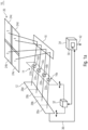
- Fig. 1a shows a schematic perspective view of a device 10 1 according to the first aspect.
- the device 10 1 includes a multi-aperture imaging device that has an image sensor 12 and an array 14 of juxtaposed optical channels 16a-e.
- the multi-aperture imaging device further comprises a beam deflecting device 18 for deflecting a beam path of the optical channels 16a-d.
- the beam paths of the optical channels 16a-d can be deflected between a lateral course between the image sensor 12 by optics 22a-d of the array 14 towards the beam deflection device 18 to a non-lateral course.
- each optical channel 16a-d images a partial field of view 24a-d of an overall field of view 26 on an image sensor area 28a-d of the image sensor 12.
- the partial fields of view 24a-d can be one-dimensional or two-dimensional, based on different focal lengths of the optics 22a-d, and also three-dimensionally distributed in space.
- the overall visual field 26 is described below in such a way that the partial visual fields 24a-d have a two-dimensional distribution, with adjacent partial visual fields 24a-d being able to overlap with one another.
- a total area of the partial visual fields results in the total visual field 26.
- the multi-aperture imaging device includes a focusing device 32 for adjusting a focus position of the multi-aperture imaging device. This can be done by changing a relative position or position between the image sensor 12 and the array 14, wherein the focusing device 32 can be designed to change a position of the image sensor 12 and / or a position of the array 14 in order to achieve a variable relative position between the Image sensor 12 and the array 14 in order to adjust the focus position of the multi-aperture imaging device.
- the relative position can be set individually for each channel, for groups of optical channels or globally. For example, a single optics 22a-d, a group of optics 22a-d or all optics 22a-d can be moved together. The same applies to the image sensor 12.
- the device includes a control device 34 which is designed to control the focusing device 32.
- the control device 34 is designed to receive image information 36 from the image sensor 12. This can be, for example, the partial fields of view 24a-d imaged on the image sensor areas 28a-d, or information or data that correspond to the images. This does not exclude intermediate processing of the image information 36, for example with regard to filtering, smoothing or the like.
- the control device 34 is configured to control the multi-aperture imaging device in a sequence of focus positions in order to capture a corresponding sequence of image information of the overall field of view 26.
- the control device 34 is designed to create a depth map 38 for the overall field of view 26 from the sequence of image information.
- the depth map 38 can be provided via a corresponding signal. Based on the different focus positions obtained by different relative positions between the image sensor 12 and the array 14, the control device 34 can capture different images of the same visual field 26 or differently focused partial images thereof in accordance with the segmentation by the partial visual fields 24a-d.
- Depth maps can be used for different purposes, for example for image editing, but also for image stitching.
- the control device 34 can thus be designed to receive individual images from the image sensor areas 28a to 28d are connected to each other using the depth map 38 to obtain image information 42 which represents the image of the overall field of view 26, that is, an overall image.
- image information 42 which represents the image of the overall field of view 26, that is, an overall image.
- the use of a depth map is particularly advantageous for such methods for joining partial images, also known as “stitching”.
- the control device can be designed to assemble the partial images of a group of partial images into an overall image.
- the depth map used for stitching can be generated from the partial images to be stitched.
- a sequence of overall images representing the entire field of view can be generated.
- Each overall image can be based on a combination of partial images with the same focus position.
- at least two, several or all overall images from the sequence can be combined to obtain an overall image with expanded information, for example to generate a bokeh effect.
- the image can also be displayed in such a way that the entire image is artificially sharp, which means that a higher number of partial areas are in focus than in the individual images, for example the entire image.
- the device 10 1 is configured to create the image of the entire field of view as a mono exposure and to create the depth map 38 from the sequence of mono exposures. Although multiple scanning of the entire field of view 26 is also possible, the device 10 can generate the depth map from a mono exposure, which can save additional exposures from different viewing directions, for example by using multiple exposures with the same device or by redundantly arranging additional optical ones Channels.
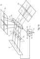
- Fig. 1b shows a schematic perspective view of a device 10 2 according to an embodiment of the second aspect.
- the device 10 2 has, instead of the control device 34, a control device 44 which is configured to control the beam deflecting device into different positions 18 1 and 18 2 .
- the beam deflection device 18 has a different relative position, so that imaging information from different overall fields of view 26 1 and 26 2 is obtained in the different positions or postures, since the beam paths of the optical channels 16a-d in different and influenced by the different positions 18 1 and 18 2 Directions can be directed.
- the device 10 2 has a control device 44 which is configured to control the beam deflecting device into the first position 18 1 in order to obtain imaging information of the first overall field of view 26 1 from the image sensor 12.
- the control device 44 is designed to control the beam deflection device 18 into the second position 18 2 in order to obtain imaging information of the second overall field of view 26 2 from the image sensor 12.
- the control device 44 is designed to insert a part of the first imaging information 46 1 into the second imaging information 46 2 in order to obtain common or accumulated image information 48.
- the accumulated image information 48 can reproduce the first overall field of view 26 in places and the second overall field of view 26 2 in places, which includes image manipulating or image processing steps. This means that the accumulated image information 48 is based in places on an image of the overall visual field 26 1 and at other locations on the image of the overall visual field 26 2 .
- the control device 44 can be designed to provide a signal 52 that contains or reproduces the accumulated image information 48.
- the image information 46 1 and/or 46 2 can also be output by the signal 52.
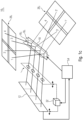
- Fig. 1c shows a schematic view of a device 10 3 according to an exemplary embodiment, which replaces the control device 34 Fig. 1a and instead of the control device 44 Fig. 1b a control device 54, which combines the functionality of the control device 34 and the control device 44 and is designed to create the depth map 38 based on a changing focus position of the device 10 3 and to output the accumulated image information 48 Fig. 1b to provide.
- Fig. 2a shows a schematic view of different focus positions 56 1 to 56 5 into which a device according to the first aspect, for example the device 10 1 and the device 10 2 , can be controlled.
- the different focus positions 56 1 to 56 5 can be understood as positions or distances 58 1 to 58 5 in which objects in the recorded overall field of view are sharply imaged on the image sensor 12.
- a number of focus positions 56 can be arbitrary and have a number greater than 1.
- Distances 62 1 to 62 4 between adjacent focus positions can refer to distances in the image space, with one embodiment or transfer of the explanation to distances is also possible in the object space.
- the advantage of considering the image space is that the properties of the imaging multi-aperture imaging device are taken into account, in particular with regard to a minimum or maximum object distance.
- the control device 34 and/or 54 can be designed to control the multi-aperture imaging device so that it has two or a higher number of focus positions 56 1 to 56 5 . In the respective focus position, individual images 64 1 and 64 2 can be captured according to the number of partial visual fields 24 recorded.
- the control device can determine by analyzing the image information to determine which of the image parts are sharp, and at what distance they are sharp Objects shown are arranged with respect to the device. This distance information can be used for the depth map 38.
- the control device can be designed to capture a corresponding number of groups of partial images in the sequence of focus positions 56 1 to 56 5 , each partial image being assigned to an imaged partial field of view. The group of partial images can therefore correspond to those partial images that depict the overall field of view in the set focus position.
- the control device can be designed to create the depth map from a comparison of local image sharpness information in the partial images.
- the local sharpness information can indicate in which areas of the image objects are sharp or sharp within a previously defined tolerance range. For example, by determining the edge blurring function and detecting the distances over which the edges extend, it can be determined whether a corresponding image area, a corresponding object or a part thereof is imaged sharply or is imaged blurry on the image sensor.
- the point image or line blurring function can be used as a quality criterion for the sharpness of an image content.
- any known optical sharpness metric such as the known Modulation Transfer Function (MTF), can be used.
- MTF Modulation Transfer Function
- the sharpness of the same objects in neighboring images of the stack, the assignment of the focus actuator position to the object distance via a calibrated lookup table and/or the direction of the through-focus scan can be used to partially recursively select from neighboring images of the Stacks to gain depth information and avoid ambiguities.
- the set focus position which is clearly correlated with an object distance that is sharply imaged, it is possible from the knowledge that the object is at least within the previously determined Tolerance range, is sharply imaged, a distance of the area of the image, the object or the part thereof can be concluded, which can be a basis for the depth map 38.
- control device can be designed to assemble the partial images of a group of partial images into an overall image. This means that the depth map used for stitching can be generated from the partial images to be stitched.
- the device can be designed to control the focusing device 32 so that the sequence of focus positions 56 1 to 56 5 is equidistant in the image space between within a tolerance range of ⁇ 25%, ⁇ 15% or ⁇ 5%, preferably as close as possible to 0% a minimum focus position and a maximum focus position.
- a tolerance range of ⁇ 25%, ⁇ 15% or ⁇ 5% preferably as close as possible to 0% a minimum focus position and a maximum focus position.
- it makes sense, but is not necessary, to control the focus positions 56 1 to 56 5 sequentially one after the other at increasing or decreasing distance. Rather, the order of the set focus positions 56 1 to 56 5 is arbitrary.
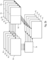
- Fig. 2b shows a schematic representation of the use of the depth map 38 and its generation.
- the partial images 64 1 and 64 2 can each be used to obtain partial information 38 1 to 38 5 of the depth map 38 from the respective focus position 56 1 to 56 5 , since the objects shown sharply in the individual images 64 1 and 64 2 are precisely related their distance can be determined. However, interpolation methods can also be used between the focus positions 56 1 and 56 5 , so that sufficiently precise information for the depth map 38 can still be obtained even with slightly out-of-focus objects.
- the distance information contained in the partial information 38 1 to 38 5 can be combined by the control device to form the depth map 38.
- the depth map 38 can be used to combine the individual images 64 1 and 64 2 from the different focus positions 56 1 to 56 5 into a corresponding number of total images 42 to 42 5 .
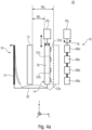
- Fig. 3a shows a schematic perspective view of a device 30 according to an exemplary embodiment.
- the image sensor 12, the array 14 and the beam deflection device 18 can span a cuboid in space.
- the cuboid can also be understood as a virtual cuboid and can, for example, have a minimum volume and in particular a minimum vertical extent along a direction parallel to one Have thickness direction y, which is parallel to a line extension direction 66.
- the line extension direction 66 runs, for example, along a z-direction and perpendicular to an x-direction, which is arranged parallel to a course of the beam paths between the image sensor 12 and the array 14.
- the directions x, y and z can span a Cartesian coordinate system.
- the minimum volume of the virtual cuboid or the minimum vertical extent of the same can be such that the virtual cuboid still includes the image sensor 12, the array 14 and the beam deflection device 18.
- the minimum volume can also be understood as describing a cuboid that is spanned by the arrangement and/or operational movement of the image sensor 12, the array 14 and/or the beam deflecting device 18.
- the line extension direction 66 can be arranged in such a way that the optical channels 16a and 16b are arranged next to one another, possibly parallel to one another, along the line extension direction 66.
- the line extension direction 66 can be arranged stationary in space.
- the virtual cuboid can have two sides which are arranged oppositely parallel to one another, parallel to the line extension direction 66 of the array 14 and parallel to a part of the beam path of the optical channels 16a and 16b between the image sensor 12 and the beam deflecting device 18. In simple terms, but without a restrictive effect, these can be, for example, a top and a bottom of the virtual cuboid.
- the two sides can span a first level 68a and a second level 68b. This means that the two sides of the cuboid can each be part of the plane 68a or 68b.
- Further components of the multi-aperture imaging device can be arranged completely, but at least partially, within the area between the planes 68a and 68b, so that the installation space requirement of the multi-aperture imaging device along the y-direction, which is parallel to a surface normal of the planes 68a and / or 68b, can be low can, which is advantageous.
- a volume of the multi-aperture imaging device may have a small or minimal installation space between the planes 68a and 68b.
- an installation space of the multi-aperture imaging device can be large or of any size.
- the volume of the virtual cuboid is influenced, for example, by an arrangement of the image sensor 12, the array 14 and the beam deflecting device 18, the arrangement of these components according to the exemplary embodiments described herein being such that the installation space of these components along the direction perpendicular to the planes and therefore the distance between the levels 68a and 68b becomes small or minimal.
- the volume and/or the distance from other sides of the virtual cuboid can be increased.
- the device 30 comprises an actuator 72 for generating a relative movement between the image sensor 12, the single-row array 14 and the beam deflection device 18.
- This can, for example, be an actuating movement of the beam deflection device 18 for switching between the in connection with the Fig. 1b include the positions described.
- the actuator 72 can be designed to act in connection with the Fig. 1a to carry out the explained relative movement to change the relative position between the image sensor 12 and the array 14.
- the actuator 72 is at least partially arranged between the levels 68a and 68b.
- the actuator 72 may be configured to move at least one of the image sensor 12, the single-row array 14 and the beam deflector 18, which may include rotational and/or translational movements along one or more directions.
- Examples of this are a channel-specific change in a relative position between image sensor areas 28 of a respective optical channel 16, the optics 22 of the respective optical channel 16 and the beam deflection device 18 or the corresponding segment or the corresponding facet and/or for channel-specific changing of an optical property of the Deflection of the beam path of the respective optical channel relevant segment/facet.
- the actuator 72 can at least partially implement autofocus and/or optical image stabilization.
- the actuator 72 can be part of the focusing device 32 and can be designed to provide a relative movement between at least one optic of at least one of the optical channels 16a and 16b and the image sensor 12.
- the relative movement between the optics 22a and/or 22b and the image sensor 12 can be controlled by the focusing device 32 so that the beam deflecting device 18 carries out a simultaneous movement.
- the distance between the beam deflection device 18 and the image sensor 12 can be reduced accordingly, so that a relative distance between the array 14 or the optics 22a and/or 22b and the Beam deflection device 18 is essentially constant. This enables the beam deflection device 18 to be designed with small beam deflection surfaces, since a beam cone that grows due to an increasing distance between the array 14 and the beam deflection device 18 can be compensated for by maintaining the distance to the beam deflection device 18.
- the focusing device 32 and/or the actuator 72 are arranged so that they protrude by a maximum of 50% from the area between the planes 68a and 68b.
- the actuator 72 may have a dimension or extension 74 parallel to the thickness direction y. A proportion of at most 50%, at most 30% or at most 10% of the dimension 74 can, starting from an area between the levels 68a and 68b, extend beyond the level 68a and / or 68b and thus protrude from the virtual cuboid. This means that the actuator 72 protrudes at most insignificantly beyond the plane 68a and/or 68b. According to exemplary embodiments, the actuator 72 does not protrude beyond the levels 68a and 68b. The advantage of this is that an expansion of the multi-aperture imaging device along the thickness direction y is not increased by the actuator 72.
- the actuator 72 can alternatively or additionally also generate a translational movement along one or more spatial directions.
- the actuator 72 can include one or more individual actuators, possibly in order to generate various individual movements in an individually controllable manner.
- the actuator 72 or at least an individual actuator thereof can, for example, be used in connection with Fig. 4 Piezo actuator described in more detail, in particular a piezoelectric bending actuator, may be implemented or include this.
- a piezo bender enables a quick and reproducible change in position. This property advantageously allows the recording of focus stacks in the sense of several or many images in a short time.
- Piezo benders, as actuators designed to be long along one dimension or direction can be used advantageously in particular in the architecture described, since they have an advantageous form factor, i.e. an extension particularly in one direction.
- the array 14 may include a substrate 78 on which the optics 22a and 22b are attached or arranged.
- the substrate 78 can be at least partially transparent through recesses or a suitable choice of material for the beam paths of the optical channels 16a and 16b, although this does not exclude the possibility that manipulations are carried out in the optical channels, for example by arranging filter structures or the like.
- Fig. 3b shows a schematic side sectional view of the device 30 according to an exemplary embodiment.
- the multi-aperture imaging device of the device 30 may, for example, have a plurality of actuators, for example more than one, more than two or another number >0.
- actuators 72 1 to 72 5 can be arranged, which can be used for different purposes, for example for adjusting the focus position and/or changing the position or position of the beam deflection device 18 for adjusting the viewing direction of the multi-aperture imaging device and/or for providing optical image stabilization rotational movement of the beam deflection device 18 and/or translational movement of the array 14.
- the actuators 72 1 to 72 5 can be arranged in such a way that they are at least partially arranged between the two levels 68a and 68b, which are spanned by sides 69a and 69b of the virtual cuboid 69.
- the sides 69a and 69b of the cuboid 69 can be aligned parallel to one another and parallel to the line extension direction of the array and part of the beam path of the optical channels between the image sensor 12 and the beam deflecting device 18.
- the volume of the cuboid 69 is minimal and still includes the image sensor 12, the array 14 and the beam deflection device 18 as well as their operational movements.
- Optical channels of the array 14 have optics 22, which can be formed the same or different from each other for each optical channel.
- a volume of the multi-aperture imaging device may have a small or minimal installation space between the planes 68a and 68b.
- an installation space of the multi-aperture imaging device can be large or of any size.
- the volume of the virtual cuboid is influenced, for example, by an arrangement of the image sensor 12, the single-row array 14 and the beam deflecting device, the arrangement of these components according to the exemplary embodiments described herein being such that the installation space of these components is along the direction perpendicular to the planes and therefore the distance between the levels 68a and 68b becomes small or minimal. Compared to other arrangements of the components, the volume and/or the distance of other sides of the virtual cuboid can be increased.
- the virtual cuboid 69 is shown by dotted lines.
- the levels 68a and 68b can include two sides of the virtual cuboid 69 or can be spanned thereby.
- a thickness direction y of the multi-aperture imaging device may be arranged normal to the planes 68a and/or 68b and/or parallel to the y-direction.
- the image sensor 12, the array 14 and the beam deflection device 18 can be arranged in such a way that a vertical distance between the planes 68a and 68b along the thickness direction y, which can be referred to as the height of the cuboid for simplicity but without any limiting effect, is minimal, whereby on a minimization of the volume, which means that the other dimensions of the cuboid can be dispensed with.
- An expansion of the cuboid 69 along the direction y can be minimal and essentially due to the expansion of the optical components of the imaging channels, i.e. i.e., the array 14, the image sensor 12 and the beam deflection device 18 can be predetermined along the direction y.
- a volume of the multi-aperture imaging device may have a small or minimal installation space between the planes 68a and 68b.
- an installation space of the multi-aperture imaging device can be large or of any size.
- the volume of the virtual cuboid is influenced, for example, by an arrangement of the image sensor 12, the single-row array 14 and the beam deflecting device, the arrangement of these components according to the exemplary embodiments described herein being such that the installation space of these components is along the direction perpendicular to the planes and therefore the distance between the levels 68a and 68b becomes small or minimal. Compared to other arrangements of the components, the volume and/or the distance of other sides of the virtual cuboid can be increased.
- the actuators 72 1 to 72 5 can each have a dimension or extension parallel to the direction y.
- a proportion of at most 50%, at most 30% or at most 10% of the dimensions of the respective actuator 72 1 to 72 5 can, starting from an area between the two levels 68a and 68b, protrude beyond the level 68a and / or 68b or protrude out of the area .
- the actuators 72 1 to 72 5 protrude at most insignificantly beyond the plane 68a and/or 68b.
- the actuators do not protrude beyond the levels 68a and 68b.
- the advantage of this is that an expansion of the multi-aperture imaging device along the thickness direction or direction y is not increased by the actuators.
- an image stabilizer can have at least one of the actuators 72 to 72 5 .
- the at least one can be arranged in a plane 71 or between the planes 68a and 68b.
- the actuators 72 1 to 72 5 can be arranged in front of, behind or next to the image sensor 12, the array 14 and/or the beam deflection device 18.
- the actuators 36 and 42 are arranged with a maximum extent of 50%, 30% or 10% outside the area between the levels 68a and 68b.
- Fig. 3c shows a schematic side sectional view of the multi-aperture imaging device, in which different overall fields of view 26 1 and 26 2 can be detected based on different positions of the beam deflection device 18, since the multi-aperture imaging device then has different viewing directions.
- the multi-aperture imaging device can be designed to change the tilting of the beam deflection device by an angle ⁇ , so that alternately different main sides of the beam deflection device 18 are arranged facing the array 14.
- the multi-aperture imaging device may include an actuator that is designed to tilt the beam deflector 18 about the rotation axis 76.
- the actuator can be designed to move the beam deflection device 18 into a first position in which the beam deflection device 18 deflects the beam path 26 of the optical channels of the array 14 in the positive y-direction.
- the beam deflection device 18 in the first position can have, for example, an angle ⁇ of >0° and ⁇ 90°, of at least 10° and at most 80° or at least 30° and at most 50°, for example 45°.
- the actuator can be designed to deflect the beam deflecting device in a second position about the axis of rotation 76 so that the beam deflecting device 18 deflects the beam path of the optical channels of the array 14 towards the negative y-direction, as indicated by the viewing direction to the overall field of view 26 2 and the dashed one Representation of the beam deflection device 18 is shown.
- the beam deflection device 18 can be designed to be reflective on both sides, so that in the first position the viewing direction points towards the overall field of view 26 1 .
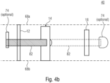
- Fig. 4a shows a schematic top view of a device 40 according to an exemplary embodiment, in which the actuator 72 is formed as a piezoelectric bending actuator.
- the actuator 72 is designed to perform a bend in the x/z plane, as shown by the dashed lines.
- the actuator 72 is connected to the array 14 via a mechanical deflection device 82, so that when the actuator 72 is bent, the array 14 can be displaced laterally along the x direction, so that the focus position can be changed.
- the actuator 72 can be connected to the substrate 78.
- the actuator 72 can also be arranged on a housing that houses at least part of the optics 22a to 22d in order to move the housing. Other variants are also possible.
- the device 40 may have further actuators 84 1 and 84 2 , which are configured to generate a movement on the array 14 and/or the beam deflection device 18, for example to position the beam deflection device 18 in different positions or positions and/or for optical purposes Image stabilization by translationally displacing the array 14 along the z-direction and/or by generating a rotational movement of the beam deflecting device 18 about the axis of rotation 76.
- actuators 84 1 and 84 2 are configured to generate a movement on the array 14 and/or the beam deflection device 18, for example to position the beam deflection device 18 in different positions or positions and/or for optical purposes Image stabilization by translationally displacing the array 14 along the z-direction and/or by generating a rotational movement of the beam deflecting device 18 about the axis of rotation 76.
- the beam deflection device 18 can have a plurality of spaced apart but common movable facets 86a to 86d, each optical channel being assigned to a facet 86a to 86d.
- the facets 86a to 86d can also be directly adjacent, i.e. H. be arranged with little or no distance from one another. Alternatively, a flat mirror can also be arranged.
- a distance 88 1 between at least one of the optics 22a-d and the image sensor 12 can be changed from a first value 88 1 to a second value 88 2 , for example increased or decreased.
- Fig. 4b shows a schematic side sectional view of the device 40 to illustrate the arrangement of the actuator 72 between the planes 68a and 68b, which is in connection with the Fig. 3a are described.
- the actuator 72 is complete, for example arranged between the levels 68a and 68b, as well as the mechanical deflection device 82, which has several force-transmitting elements, for example connecting webs, wires. Ropes or the like and may have mechanical bearings or deflection elements.
- the mechanical deflection device or mechanical device for transmitting the movement to the array 14 can be arranged on a side of the image sensor 12 that faces away from the array 14, i.e. h, starting from the array 14 behind the image sensor 12.
- the mechanical device 82 can be arranged such that a force flow passes laterally past the image sensor 12.
- the actuator 72 or another actuator can be arranged on a side of the beam deflection device 18 facing away from the array 14, i.e. i.e., starting from the array 14 behind the beam deflection device 18.
- the mechanical device 82 can be arranged so that a force flow passes laterally past the beam deflection device 18.
- actuator 72 Although only one actuator 72 is shown, a larger number of actuators can also be arranged and/or more than one side of the actuator 72 can be connected to a mechanical deflection device 82.
- a centrally mounted or supported actuator 72 can be connected on both sides to a mechanical deflection device 82 and, for example, engage on both sides of the array 14 in order to enable homogeneous movement.
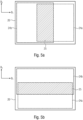
- Fig. 5a shows a schematic representation of an arrangement of partial visual fields 24a and 24b in an overall visual field 26, which can be detected, for example, by a multi-aperture imaging device described herein, such as the multi-aperture imaging device 10 1 , 10 2 , 10 3 , 30 and/or 40 and, for example, the overall visual field 26 1 and/or 26 2 can correspond.
- the overall field of view 26 can be imaged with the optical channel 16b on the image sensor area 28b.
- the optical channel 16a may be configured to capture the partial field of view 24a and image it onto the image sensor area 28a.
- Another optical channel, such as the optical channel 16c can be designed to capture the partial field of view 24b and image it on the image sensor area 28c. This means that a group of optical channels can be designed to capture exactly two partial fields of view 24a and 24b.
- a simultaneous detection of the overall visual field and the partial visual fields, which together in turn represent the overall visual field 26, can therefore take place.
- the partial fields of view 24a and 24b can have the same or comparable extent along at least one image direction B 1 or B 2 , for example along the image direction B 2 .
- the extent of the partial visual fields 24a and 24b can be identical to the extent of the overall visual field 26 along the image direction B 2 . This means that the partial visual fields 24a and 24b can completely capture or record the overall visual field 26 along the image direction B 2 and only partially capture or record the overall visual field along another image direction B arranged perpendicular thereto and can be arranged offset from one another, so that they are also combinatorially along the second direction results in a complete capture of the entire field of view 26.
- the partial fields of view 24a and 24b can be disjoint to one another or, at most, overlap with one another incompletely in an overlap region 25, which possibly extends completely along the image direction B 2 in the overall field of view 26.
- a group of optical channels comprising the optical channels 16a and 16c can be designed to, taken together, completely image the overall field of view 26, for example through an overall image in combination with partial images which, taken together, image the entire field of view.
- the image direction B can be, for example, a horizontal line of an image to be provided.
- the image directions B 1 and B 2 represent two different image directions positioned arbitrarily in space.
- Fig. 5b shows a schematic representation of an arrangement of the partial fields of view 24a and 24b, which are arranged offset from one another along another image direction, the image direction B 2 , and overlap one another.
- the partial visual fields 24a and 24b can capture the overall visual field 26 along the image direction B, completely and incompletely along the image direction B 2 .
- the overlap area 25 is, for example, arranged completely in the overall facial area 26 along the image direction B 1 .
- Fig. 5c shows a schematic representation of four partial visual fields 24a to 24b, which incompletely capture the overall visual field 26 in both directions B 1 and B 2 .
- Two adjacent partial fields of view 24a and 24b overlap in an overlap area 25b.
- Two overlapping partial visual fields 24b and 24c overlap in an overlap area 25c.
- partial visual fields 24c and 24d overlap in an overlap region 25d and the partial visual fields 24d with that Partial fields of view 24a in an overlap area 25a. All four partial visual fields 24a to 24d can overlap in an overlap area 25e of the overall visual field 26.
- a multi-aperture imaging device can be used similar to that in connection with Fig. 1a-c described, whereby the array 14 can have, for example, five optics, four for detecting partial fields of vision 24a-d and one optic for detecting the overall field of view 26. Accordingly, the array can be used in connection with Fig. 5a-b be designed with three optical channels.
- a large amount of image information is available in the overlap areas 25a to 25e.
- the overlap area 25b is detected over the overall field of view 26, the partial field of view 24a and the partial field of view 24b.
- An image format of the overall visual field can correspond to a redundancy-free combination of the imaged partial visual fields, for example the partial visual fields 24a-d in Fig. 5c , whereby the overlap areas 25a-e are only counted once. In connection with the 5a and 5b This applies to the redundancy-free combination of the partial visual fields 24a and 24b.
- An overlap in the overlap areas 25 and/or 25a-e can, for example, comprise at most 50%, at most 35% or at most 20% of the respective partial images.
- a reduction in the number of optical channels can be achieved, which enables cost savings and enables a reduction in the lateral space requirement.
- an alternative form of depth information acquisition to stereoscopic detection is made possible, which does not require corresponding additional sensors such as time of flight (time of flight measurement), structured or coded light (structured or coded light) and the like. Time of flight sensors that enable low resolution and structured light sensors that require high energy can therefore be avoided. Both approaches continue to have problems in strong ambient lighting, particularly sunlight.
- a piezo bender serves as an extremely fast focus factor with low power consumption.
- embodiments provide for combining the acquisition of depth information from the sequence of focus positions with the acquisition of depth information from disparity-based depth information.
- one is preferred to create a disparity-based depth map and, in the event that it has deficiencies, to supplement, correct or improve it with the additional depth information through the sequence of focus positions.
- the described architecture of the multi-aperture imaging device enables the use of such piezo benders, since an otherwise cubic form factor of the camera module makes the use of long piezo benders more difficult or even impossible. With a short exposure time, this allows the recording of focus stacks, ie numerous images taken in quick succession with slightly different focussing of the scene.
- Embodiments provide that the entire depth of the scene is sensibly sampled, for example from macro, the closest possible shot, to infinity, which means the furthest possible distance.
- the distances can be arranged equidistantly in the object space, but preferably in the image space. Alternatively, another sensible distance can be selected.
- a number of the focus positions is, for example, at least two, at least three, at least five, at least ten, at least 20 or any other arbitrary number.
- Multiple images 42 can be displayed to the user.
- exemplary embodiments provide for combining the individual image information so that the user can be provided with an image that has combined image information.
- an image with depth information which offers the possibility of digital refocusing, for example.
- the displayed image can offer a so-called bokeh effect, a blurring.
- the image can also be displayed in such a way that the entire image is artificially sharp, which means that a larger distance area than in the individual images of partial areas is in focus, for example the entire image.
- the sharpness or blur measured in the individual images and other information can be used to assign the focus actuator position to an object distance, for example using a calibrated lookup Table, a direction of the focus position sequence (through-focus scan) itself but also recursively from other images in order to avoid ambiguities, reconstruct the object distance of the individual elements of the scene and use it to create a depth map in image resolution.
- duplication of the channels for a stereo image can be omitted and a depth map can still be created.
- This depth map enables image stitching of the different partial images of the multi-aperture imaging device. For example, by halving the number of optical channels A significant reduction in the lateral dimensions, for example along the direction of the number extension, can be achieved and thus a price reduction can also be achieved.
- Image processing can deliver images that are at least as good through other steps. Alternatively or additionally, it is possible to dispense with an additional arrangement of time of flight sensors or structured light sensors. This advantage remains even if the mentioned duplication is still carried out, which can also offer advantages.
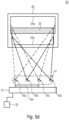
- the overall field of view 26 can be recorded at least stereoscopically, as in, for example DE 10 2013 222 780 A1 is described in order to obtain depth information from the multiple, ie at least twice, detection of the entire visual field or the partial visual fields 24.
- the at least stereoscopic recording for example in Fig. 5d is shown, enables depth information to be obtained by viewing the same partial field of view 24a or 24b through two optical channels 16a and 16c or 16c and 16d spaced apart by a base distance BA.
- a number of the partial visual fields can be freely selected, as can their arrangement, see the differences in the examples Fig. 5a-c .
- the in. is advantageous with regard to avoiding occlusions Fig. 5d Arrangement of the partial fields of view shown in accordance with Fig. 5b .
- Fig. 5d only a portion of a multi-aperture imaging device 50 is shown. Elements such as the beam deflection device 18 or actuators are not shown. There are now two sources of depth information for the multi-aperture imaging device 50 that can be used to create a depth map. On the one hand, the control of the multi-aperture imaging device in a sequence of focus positions, and on the other hand, the disparity between optical channels to capture consistent image content.
- the disparity-based depth information due to occlusions or coverings can be patchy or of low quality in places, but in contrast to the sequence of focus positions, it can be quick and requires little electrical energy for actuators and/or computing power (which requires both appropriate computing resources and electrical energy). ) take place.
- Embodiments therefore provide for combining the depth information from both information sources.
- a preliminary depth map can be created from the disparity-based depth information and supplemented or improved by a completely or partially created additional depth map from the sequence of focal positions.
- the preliminary depth map does not necessarily describe a temporal connection, since the order in which the two depth maps to be combined are created can be arbitrary.
- the preliminary depth map can be created from the sequence of focal positions and improved or enhanced by disparity-based depth information.
- the controller 34 or another instance of the multi-aperture imaging device 50 may be configured to check a quality or reliability of the depth information or depth map, for example by checking a resolution of the depth information and/or monitoring the occurrence of occlusions or other effects.
- additional depth information can be created from the sequence of focal positions in order to improve or correct the preliminary depth map.
- this additional depth information can be obtained in an energy and/or computationally efficient manner by only creating the sequence of focus positions for the areas of the preliminary depth map to be supplemented, i.e. i.e., only in a partial area of the depth map.
- Embodiments provide that the control device specifies a local area and/or an area of the depth levels for determining the depth information based on the sequence of focus positions, ie, a value range between the minimum and maximum focus position based on the locations to be supplemented or corrected in the preliminary depth map, whereby several areas can also be set.
- a local area and/or an area of the depth levels for determining the depth information based on the sequence of focus positions ie, a value range between the minimum and maximum focus position based on the locations to be supplemented or corrected in the preliminary depth map, whereby several areas can also be set.
- control device can be designed to recalculate the depth information only for those areas of the overall field of view 26 in which an improvement, optimization or correction of the preliminary depth map is required, which also requires energy - and can be time-saving.
- the control device can be designed to select areas of the overall field of view in the preliminary depth map based on a quality criterion for which an improvement is required, and to supplement the preliminary depth map in the selected areas and not to supplement it in non-selected areas.
- the additional depth information to supplement the preliminary depth map can only be determined for the selected areas and cannot be determined for non-selected areas.
- the control device can be designed to determine the at least one area and/or the focus positions by carrying out a comparison that indicates whether the quality or reliability of the depth map in the specific area corresponds to at least a threshold value.
- a negative quality criterion such as number of errors or the like
- the aforementioned preliminary depth map may be a depth map created using the available depth information.
- the preliminary depth map can be understood as a collection of depth information (without a specific map format).
- Embodiments relate to the aspect of combining depth maps from disparity and focus stacks. Embodiments are based on the described architecture with more than 2 channels, which obtains a depth map primarily from the naturally present disparity/parallax of the channels. Depending on the calculation and/or power budget, a further depth map can either always be generated from focus stacks and combined with the first depth map to improve it (essentially filling holes in coverages) and improve the stitching results, or preferably only after obvious deficiencies have been identified be generated from disparity in the depth map. A different order is less preferred, since the generation of the focus stacks can involve additional energy expenditure and possibly considerable loss of time or, as a result, significantly complicated exposure conditions of the sequential individual images.
- Advantages that may result from the additional use of a depth map, generated from focus stacks of images taken extremely quickly one after the other, are: fewer holes in the depth map due to occlusions, possibly additional depth levels, especially for larger object distances, possibly improved lateral resolution of the depth map and Overall, through additional information acquisition, an improved signal-to-noise ratio in the depth map and thus fewer ambiguities or even ambiguities, which would otherwise lead to artifacts in the stitched images of the overall field of view.
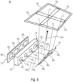
- Fig. 6 shows a schematic perspective view of a device 60 according to an exemplary embodiment with regard to the second aspect.
- the described embodiments also apply without further ado to the devices 10 1 , 10 3 , 30 and/or 40.
- the device 60 or the multi-aperture imaging device of the device 60 can capture two entire fields of view 26 1 and 26 2 that are spaced apart from one another.
- the device 60 is formed, for example, as a portable or mobile device, in particular a tablet computer or a mobile phone, in particular a smartphone (intelligent telephone).
- One of the fields of view 26 1 and 26 2 can be arranged, for example, along a user direction of the device 60, as is common, for example, in the context of self-photographs (selfies) for photos and/or videos.
- the other overall field of view may, for example, be arranged along an opposite direction and/or a world direction of the device 60 and, for example, be arranged along the direction along which the user looks when looking at the device 60 along the user direction, starting from the overall field of view.
- the beam deflection device 18 in Fig. 1b be formed reflective on both sides and, for example, deflect the beam path of the optical channels 16a-d in different positions with different main sides, so that, starting from the device 60, the overall fields of view 26 1 and 26 2 are arranged opposite one another and/or at an angle of 180 °.
- Fig. 7a shows a schematic diagram to illustrate the processing of the image information 46 1 and 46 2 , which can be obtained by imaging the overall visual fields 26 1 and 26 2 .
- the control device is designed to separate a part 92 of the imaging information 46 1 of the field of view 26 1 , for example to cut out, isolate or only copy the part 92.
- the control device is further designed to combine the separated or segmented part 92 with the imaging information 46 2 , that is, to insert the part 92 into the imaging information 46 2 to obtain the accumulated image information 48. This has the overall field of view 26 2 in places and the image information 46 1 in places, namely where the part 92 was inserted.
- obtaining the accumulated image information 48 is not limited to the insertion of a single part 92, but that any number of parts 92 from the image information 46 1 can be segmented and one, more or all of these parts into the image information 46 2 can be inserted.
- a location or position at which the part 92 is inserted into the second imaging information 46 2 can be automatically determined by the control device, for example by projecting the part 92 through the device 60 into the second field of view 26 2 , but can alternatively be or can also be selected by a user.
- the control device is designed to identify and segment a person in the first imaging information 46 1 , for example via pattern comparison and/or edge detection, but in particular on the basis of the depth map generated by the device itself.
- the control device can be designed to insert the image of the person into the second image information 46 2 in order to obtain the accumulated image information 48.
- the part 92 can be a person, for example a user of the device 60.
- the device is designed to automatically identify the person and to automatically identify the image of the person, that is, the part 92 to be inserted into the second mapping information 46 2 . This makes it possible to automatically take a self-portrait or to take a self-photograph in front of or in the second overall field of view 26 2 without having to laboriously position the device 60 and/or without having to laboriously position the user.
- Embodiments provide that the control device uses a depth map, such as the depth map 38, to position the part 92 in the second imaging information 46 2 .
- the depth map 38 may have a plurality or multiplicity of depth levels, for example, according to the number of focus positions taken into account or a reduced number obtained therefrom or a higher number interpolated therefrom.
- the control device can be designed to insert the part 92 in the predetermined depth plane of the second image information 46 2 in order to obtain the accumulated image information 48.
- the predetermined depth plane can essentially, ie, within a tolerance range of ⁇ 10%, ⁇ 5% or ⁇ 2%, correspond to a distance of the first overall field of view 26 2 from the device 60 or the distance of the segmented part 92 from the device 60. This can also be referred to as depth-correct insertion of the part 92 into the second imaging information 46 2 .
- Fig. 7b shows a schematic representation of a scaling of the part 92 in the accumulated image information 48.
- a different depth level can also be selected, with various possible exemplary embodiments being provided for this.
- the predetermined depth plane may be influenced or determined by the placement of the part 92 in the second imaging information 46 2 .
- the placement can be done automatically or through user input.
- the control device can be designed to set a distance in the second imaging information 46 2 of the area in which the part 92 is to be inserted determine. Knowing the distance of the part 92 to the device and the objects in the second imaging information 46 2 , for example using depth maps, a virtual change in the distance of the part 92 caused by the user input can be compensated for by scaling the part 92.
- a one-dimensional, two-dimensional or three-dimensional size 94 of the part 92 can be changed into a size 96, for example reduced if the distance of the part 92 from the first imaging information 46 1 to the second imaging information 46 2 is increased, or increased if the distance from the first mapping information 46 1 to the second imaging information 46 2 is reduced.
- the device can be configured to scale the mapping information 46 1 to obtain scaled mapping information.
- the scaled image information can be inserted into the image information 46 2 by the controller to obtain the accumulated image information 48.
- the device may be configured to determine a distance of an object that represents the part 92 and that is imaged in the first imaging information 46 1 with respect to the device 60.
- the device can scale the imaging information 46, or the part 92 thereof, based on a comparison of the determined distance with the predetermined depth plane in the second imaging information 46 2 . It is advantageous if the two imaging pieces of information 46 1 and 46 2 are recorded at short time intervals. It is advantageous if this time interval is approximately 0.1 ms within a time interval of at most 30 ms, at most 10 ms, at most 5 ms or at most 1 ms. This time can be used, for example, for switching or repositioning the beam deflection device and can be at least partially determined by the duration of this process.
- the accumulated image information 48 can be obtained as a single image, alternatively or additionally also as a video data stream, for example as a large number of individual images.
- a device in accordance with the second aspect is formed such that the first imaging information 46 1 includes an image of a user and the second imaging information 46 2 includes a world view of the device.
- the control device is designed to segment an image of the user from the first imaging information 46 1 and insert it into the world view. For example, the device can be depicted in order to insert the user's image into the world view in the correct depth.
- the selfie shot can be combined with the image taken on the world side as a background, without having to turn the phone 180°, as would otherwise be necessary, in order to record yourself in front of this scene.
- photographs are taken backwards, which means that the orientation of the phone in relation to the scene must always be thought of in a mirror image.
- the depth map itself can also be generated, as described in connection with the first aspect, so that the additional arrangement of time of flight sensors or structured light sensors can be dispensed with.
- Fig. 8 shows parts of a multi-aperture imaging device 80 that can be used in devices according to the invention of the first and / or second aspect, wherein one possible focusing device and/or actuators for implementing optical image stabilization are not shown, but can be easily implemented.
- the multi-aperture imaging device 80 of Fig. 8 comprises an array 14 formed in several lines or preferably a single line of optical channels 16a-d arranged next to one another.
- Each optical channel 16a-d includes optics 22a-d for imaging a respective partial field of view 24a-d of an overall field of view 26, possibly also of an entire field of view, as in connection with Fig. 5 is described.
- the imaged field of view of the multi-aperture imaging device 80 is imaged onto a respectively assigned image sensor area 28a-d of an image sensor 12.
- the image sensor areas 28a-d can, for example, each be formed from a chip that includes a corresponding pixel array, the chips as in the Fig. 8 indicated, can be mounted on a common substrate or a common circuit board 98.
- the image sensor areas 28a-d can each be formed from a part of a common pixel array that extends continuously or with interruptions over the image sensor areas 28a-d, with the common pixel array being formed, for example, on a single chip. For example, only the pixel values of the common pixel array in the image sensor areas 28a-d are then read out.
- Various mixtures of these alternatives are of course also possible, such as: B. the presence of a chip for two or more channels and another chip for other channels or the like. In the case of several chips of the image sensor 12, these can, for example, be mounted on one or more circuit boards, for example all together or in groups or the like.
- optical channels 16a-d are arranged in a single row next to each other in the line extension direction of the array 14, but the number four is only exemplary and could also take any other number greater than one, that is, N optical channels can be arranged with N>1.
- the array 14 can also have further lines that extend along the line extension direction.
- An array 14 of optical channels 16a-d is understood to be a combination of the optical channels or a spatial grouping thereof.
- the optics 22a-d can each have a lens but also a lens composite or lens stack as well as a combination of imaging optics with other optical elements, including filters, Apertures, reflective or diffractive elements or the like.
- the array 14 can be designed in such a way that the optics 22a-d are arranged, fastened or mounted on the substrate 78 individually for each channel, in groups or globally, ie all channels together. This means that a single substrate 78, several parts thereof or even no substrate 78 can be arranged, for example if the optics 22a-d are held elsewhere.
- optical axes or the beam paths 102a-d of the optical channels 16a-d can run parallel to one another between the image sensor areas 28a-d and the optics 22a-d.
- the image sensor areas 28a-d are arranged, for example, in a common plane, as are the optical centers of the optics 22a-d. Both planes are parallel to each other, i.e. parallel to the common plane of the image sensor areas 28a-d.
- optical centers of the optics 22a-d coincide with centers of the image sensor areas 28a-d.
- the optics 22a-d on the one hand and the image sensor areas 28a-d are arranged in these parallel planes with the same repetition distance in the line extension direction.
- An image-side distance between image sensor areas 28a-d and the associated optics 22a-d is set so that the images on the image sensor areas 28a-d are set to a desired object distance.
- the distance is, for example, in a range equal to or greater than the focal length of the optics 22a-d or, for example, in a range between one and two times the focal length of the optics 22a-d, both inclusive.
- the image-side distance along the optical axis 102a-d between image sensor area 28a-d and optics 22a-d can also be adjustable, such as manually by a user and/or automatically via a focusing device or an autofocus control.
- the beam deflection device 18 deflects the beam paths 102a-d or optical axes, for example with a channel-specific deviation, into an overall field of view direction 104.
- the overall field of view direction 104 runs, for example, parallel to a plane that is perpendicular to the line extension direction of the array 14 and parallel to the course of the optical axes 102a-d before or without beam deflection.
- the overall field of view direction 104 emerges from the optical axes 102a-d by rotation about the line extension direction by an angle that is >0° and ⁇ 180° and is, for example, between 80 and 100° and can be, for example, 90°.
- the overall field of view 26 of the multi-aperture imaging device 80 which corresponds to the overall coverage of the partial fields of view 24a-d, is therefore not in the direction of an extension of the series connection of the image sensor 12 and the array 14 in the direction of the optical axes 102a-d, but rather the overall field of view is located due to the beam deflection laterally to image sensor 12 and array 14 in a direction in which the overall height of multi-aperture imaging device 80 is measured, ie the lateral direction perpendicular to the line extension direction.
- the beam deflection device 18 deflects, for example, each beam path or the beam path of each optical channel 16a-d with a channel-specific deviation from the deflection just mentioned leading to the direction 104.
- the beam deflection device 18 includes, for example, an individually configured element for each channel 16a-d, such as a reflective facet 86-d and/or a reflective surface. These are slightly inclined towards each other. The mutual tilting of the facets 86a-d is selected such that when the beam is deflected by the beam deflection device 18, the partial fields of view 24a-d are provided with a slight divergence, such that the partial fields of view 24a-d only partially overlap.
- the individual deflection can also be designed in such a way that the partial visual fields 24a-d cover the overall visual field 26 two-dimensionally, ie are arranged two-dimensionally distributed in the overall visual field 26.
- the optics 22a-d of an optical channel can be set up to completely or partially generate the divergence in the beam paths 102a-d, which makes it possible to completely or partially dispense with the inclination between individual facets 86a-d. If, for example, the divergence is provided entirely by the optics 22a-d, the beam deflection device can also be formed as a flat mirror.
- the beam deflection device 18 can also be designed differently than what has been described so far.
- the beam deflection device 18 does not necessarily have a reflective effect. So she can too be designed differently than in the form of a facetted mirror, such as in the form of transparent prism wedges.
- the average beam deflection could be 0°, that is, the direction 104 could, for example, be parallel to the beam paths 102a-d before or without beam deflection or, in other words, the multi-aperture imaging device 80 could continue to "look straight ahead" despite the beam deflection device 18.
- the channel-specific deflection by the beam deflection device 18 would again lead to the partial visual fields 24a-d only slightly overlapping one another, for example in pairs with an overlap ⁇ 10% based on the solid angle ranges of the partial visual fields 24a-d.
- the beam paths 102a-d or optical axes could also deviate from the described parallelism and yet the parallelism of the beam paths of the optical channels could still be so pronounced that the partial fields of view that are covered or on by the individual channels 16a-N the respective image sensor areas 28a-d are imaged, without further measures, such as beam deflection, would largely overlap, so that in order to cover a larger overall field of view by the multi-aperture imaging device 80, the beam deflection device 18 provides the beam paths with an additional divergence in such a way that the Partial fields of view of N optical channels 16a-N overlap less with each other.
- the beam deflection device 18 ensures, for example, that the overall field of view has an opening angle that is greater than 1.5 times the opening angle of the individual partial fields of view of the optical channels 16a-N.
- the beam paths 102a-d it would also be possible that, for example, not all facet inclinations differ, but that some groups of channels, for example, have facets with the same inclination. The latter can then be formed in one piece or continuously merging into one another, so to speak as a facet that is assigned to this group of channels adjacent in the direction of the line extension.
- the divergence of the optical axes 102a-d of these channels 16a-d could then come from the divergence of these optical axes 102a-d, as caused by lateral offset between optical centers of the optics 22a-d and image sensor areas 28a-d of the channels 16a-d or Prism structures or decentered lens cutouts are achieved.
- the preliminary divergence could, for example, be limited to one level.
- the optical axes 102a-d could, for example, run in a common plane before or without beam deflection 18, but divergent in this, and the facets 86a-d only cause an additional divergence in the other transverse plane, ie they are all parallel to the line extension direction and only inclined differently to one another to the aforementioned common plane of the optical axes 102a-d, whereby here again several facets 86a-d can have the same inclination or could be assigned to a group of channels whose optical axes are, for example already in the aforementioned common plane of the optical axes in pairs before or without beam deflection.
- the entire divergence could also be achieved by the lateral offset between optical centers of the optics 22a-d on the one hand and centers of the image sensor areas 28a-d on the other hand or by prism structures or decentered lens cutouts.
- the mentioned possible preliminary divergence can be achieved, for example, by the optical centers of the optics 22a-d lying on a straight line along the line extension direction, while the centers of the image sensor areas 28a-d depend on the projection of the optical centers along the normal of the plane of the Image sensor areas 28a-d are arranged differently at points on a straight line in the image sensor plane, such as at points that are channel-specific from the points on the aforementioned straight line in the image sensor plane along the line extension direction and / or along the direction perpendicular to both the line extension direction and the image sensor normal differ.
- advance divergence can be achieved by having the centers of the image sensors 28a-d lie on a straight line along the line extension direction, while the centers of the optics 22a-d depend on the projection of the optical centers of the image sensors along the normal to the plane of the optical centers of the optics 22a-d are arranged differently at points on a straight line in the optical center plane, such as, for example, at points that are channel-specific from the points on the aforementioned straight line in the optical center plane along the line extension direction and / or along the direction perpendicular to both the line extension direction and the normal of the Optical center level differ.
- the aforementioned channel-specific deviation from the respective projection only runs in the line extension direction, i.e. the optical axes 102a-d are only in a common plane and are provided with a pre-divergence. Both optical centers and image sensor area centers then lie on a straight line parallel to the line extension direction, but with different ones Intermediate distances.
- a lateral offset between lenses and image sensors in a perpendicular lateral direction to the line extension direction led to an increase in the overall height.
- a purely in-plane offset in the line extension direction does not change the overall height, but this may result in fewer facets and/or the facets only have a tilt in an angular orientation, which simplifies the structure.
- an apparatus includes: a multi-aperture imaging device having: an image sensor 12; an array 14 of optical channels 16a-d arranged next to one another, each optical channel 16a-d comprising optics 22a-d for imaging at least a partial field of view 24a-d of an overall field of view 26 1 , 26 2 onto an image sensor area 28a-d of the image sensor 12, a beam deflecting device 18 for deflecting a beam path 104 of the optical channels 16a-d, a focusing device 32 for adjusting a focus position of the multi-aperture imaging device; the device further comprising: a control device 34; 54, which is designed to control the focusing device 32 and to receive image information 36 from the image sensor 12; wherein the control device 34; 54 is configured to control the multi-aperture imaging device in a sequence of focus positions 56 to capture a corresponding sequence of image information 36 of the overall field of view 26 1 , 26 2 , and to create a depth map 38 for the captured overall field of view based
- control device is designed to create the depth map 38 from the sequence of image information 36.
- the optical channels are designed to at least stereoscopically capture the entire field of view; wherein the controller is configured to create a preliminary depth map based on disparity information obtained from the optical channels; and to supplement the preliminary depth map based on depth information based on the sequence of image information to obtain the depth map 38; or where the Control device is designed to create a preliminary depth map based on the sequence of image information; and to supplement the preliminary depth map based on depth information based on disparity information obtained from the optical channels to obtain the depth map 38.
- control device is configured to select regions of the overall field of view in the preliminary depth map that require improvement based on a quality criterion, and to provide additional depth information for supplementing the preliminary depth map to determine the selected areas and not to determine for non-selected areas.
- the controller 34; 54 designed to capture a corresponding number of groups of partial images 64 in the sequence of focus positions 56, each partial image 64 being assigned to an imaged partial field of view 24a-d; to create the depth map 38 from a comparison of local image sharpness information in the partial images 64; and to assemble the partial images 64 of a group of partial images into an overall image 42 using the depth map 38.
- the device is designed to control the focusing device 32 so that the sequence of focus positions 56 is distributed equidistantly in the image space between a minimum focus position and a maximum focus position within a tolerance range of 25% is.
- the device is designed to generate a sequence of overall images 42 representing the overall field of view 26 1 , 26 2 based on the sequence of image information 36, each overall image 42 being based on a combination of Partial images 64 of the same focus position 56 are based.
- the device is designed to change an overall image 42 reproducing the overall field of view 26 1 , 26 2 based on the depth map 38.
- the device is configured to display an image of the entire field of view 26 1 , 26 2 as To create a mono recording and to create the depth map 38 from the sequence of mono recordings.
- a first optical channel 16a of the array 14 is formed to provide a first partial field of view 24a of the overall field of view 26 1 ; 26 2 , wherein a second optical channel 16b of the array 14 is designed to provide a second partial field of view 24b of the overall field of view 26 1 ; 26 2 to image, and wherein a third optical channel 24c is formed to the overall field of view 26 1 ; 26 2 to be depicted completely.
- the focusing device 32 has at least one actuator 74 for adjusting the focus position 56, wherein the focusing device 32 is arranged so that it is at least partially arranged between two planes 68a, 68b, which are spanned by sides 69a, 69b of a cuboid 69, the sides 69a, 69b of the cuboid 69 being parallel to one another and to a line extension direction 2 of the array 14 and a part of the beam path 104 of the optical channels 16a-d between the image sensor 12 and the beam deflecting device 18 are aligned and its volume is minimal and still includes the image sensor 12, the array 14 and the beam deflection device 18.
- the multi-aperture imaging device has a thickness direction y arranged normal to the two planes 68a, 68b, the actuator 74 having a dimension parallel to the thickness direction y and a proportion of at most 50% of the Dimension starting from an area between the two levels 68a, 68b extends beyond the two levels 68a, 68b.
- the focusing device 32 comprises an actuator 74 for providing a relative movement between an optics 22a-d of at least one of the optical channels 16a-d and the image sensor 12.
- the focusing device 32 is designed to carry out the relative movement between the optics 22a-d of one of the optical channels 16a-d and the image sensor 12 while executing a movement of the beam deflecting device 18 simultaneous to the relative movement.
- the focusing device 32 is arranged to protrude from the area between the planes 68a, 68b by at most 50%.
- the at least one actuator 74 of the focusing device 32 includes a piezoelectric bending actuator.
- the focusing device 32 comprises at least one actuator 74 configured to provide movement and a mechanical device 82 for transmitting the movement to the array 14 for adjusting the focus position 56; wherein the actuator 74 is arranged on a side of the image sensor 12 facing away from the array 14 and the mechanical device 82 is arranged such that a force flow runs laterally past the image sensor 12; or wherein the actuator 74 is arranged on a side of the beam deflection device 18 facing away from the array 14 and the mechanical device 82 is arranged such that a force flow runs laterally past the beam deflection device 18.
- a relative position of the beam deflection device 18 is switchable between a first position and a second position, so that in the first position the beam path 104 is deflected in the direction of a first overall field of view 26 1 and in the second position, the beam path is deflected in the direction of a second overall field of view 26 2 ;
- the one control device is designed to control the beam deflecting device 18 into the first position in order to obtain imaging information 46 1 of the first overall field of view 26 1 from the image sensor 12; to control the beam deflector 18 to the second position to obtain imaging information 46 2 of the second overall field of view 26 2 from the image sensor 12; and to insert a part of the first imaging information 46 1 into the second imaging information 46 2 to obtain accumulated image information 48 which in places represents the first overall field of view 26 1 and in places the second overall field of view 26 2 .
- the multi-aperture imaging device includes: an image sensor 12; an array 14 of optical channels 16a-d arranged next to one another, each optical channel 16a-d having optics 22a-d for imaging at least a partial field of view 24a-d of an overall field of view 26 1 , 26 2 on an image sensor area 28a-d of the image sensor 12 includes a beam deflecting device 18 for deflecting a beam path 104 of the optical channels 16a-d, and a focusing device 32 for adjusting a focus position of the multi-aperture imaging device.
- the device also has a control device 34; 54, which is designed to control the focusing device 32 and to receive image information 36 from the image sensor 12; wherein the control device 34; 54 is configured to control the multi-aperture imaging device in a sequence of focus positions 56 in order to capture a corresponding sequence of image information 36 of the overall field of view 26 1 , 26 2 , and to create a depth map 38 for the captured overall field of view from the sequence of image information 36 .
- aspects have been described in connection with a device, it is understood that these aspects also represent a description of the corresponding method, so that a block or a component of a device is also to be understood as a corresponding method step or as a feature of a method step. Analogously, aspects that have been described in connection with or as a method step also represent a description of a corresponding block or detail or feature of a corresponding device.
Abstract
Eine erfindungsgemäße Vorrichtung umfasst eine Multiaperturabbildungsvorrichtung mit einem Bildsensor (12); einem Array (14) von nebeneinander angeordneten optischen Kanälen (16a-d), wobei jeder optische Kanal (16a-d) eine Optik (22a-d) zur Abbildung zumindest eines Teilgesichtsfeldes (24a-d) eines Gesamtgesichtsfeldes (26<sub>1</sub>, 26<sub>2</sub>) auf einen Bildsensorbereich (28a-d) des Bildsensors (12) umfasst, einer Strahlumlenkeinrichtung (18) zum Umlenken eines Strahlengangs (104) der optischen Kanäle (16a-d), und einer Fokussiereinrichtung (32) zum Einstellen einer Fokuslage der Multiaperturabbildungsvorrichtung. Die Vorrichtung weist ferner eine Steuereinrichtung (34; 54) auf, die ausgebildet ist, um die Fokussiereinrichtung (32) zu steuern und um Bildinformationen (36) von dem Bildsensor (12) zu empfangen; wobei die Steuereinrichtung (34; 54) konfiguriert ist, um die Multiaperturabbildungsvorrichtung in eine Abfolge von Fokuslagen (56) zu steuern, um eine korrespondierende Abfolge von Bildinformationen (36) des Gesamtgesichtsfeldes (26<sub>1</sub>, 26<sub>2</sub>) zu erfassen, und basierend auf der Abfolge von Bildinformationen (36) eine Tiefenkarte (38) für das erfasste Gesamtgesichtsfeld zu erstellen.A device according to the invention comprises a multi-aperture imaging device with an image sensor (12); an array (14) of optical channels (16a-d) arranged next to one another, each optical channel (16a-d) having optics (22a-d) for imaging at least a partial field of view (24a-d) of an overall field of view (26<sub>1 </sub>, 26<sub>2</sub>) on an image sensor area (28a-d) of the image sensor (12), a beam deflection device (18) for deflecting a beam path (104) of the optical channels (16a-d) , and a focusing device (32) for adjusting a focus position of the multi-aperture imaging device. The device further has a control device (34; 54) which is designed to control the focusing device (32) and to receive image information (36) from the image sensor (12); wherein the control device (34; 54) is configured to control the multi-aperture imaging device in a sequence of focus positions (56) in order to produce a corresponding sequence of image information (36) of the overall field of view (26<sub>1</sub>, 26<sub >2</sub>), and based on the sequence of image information (36) to create a depth map (38) for the recorded overall field of view.
Description
Die vorliegende Erfindung bezieht sich auf Multiaperturabbildungsvorrichtungen, insbesondere eine Vorrichtung mit einer Multiaperturabbildungsvorrichtung. Die Vorrichtung ist konfiguriert, um die von der Multiaperturabbildungsvorrichtung enthaltenen Informationen zur Erstellung einer Tiefenkarte und/oder zum Akkumulieren von Bildinformationen zu verwenden. Die vorliegende Erfindung bezieht sich ferner auf Tiefeninformationsgewinnung aus Fokus-Stacks mit einer Array-Kamera und/oder ein Selbstportrait vor verändertem Hintergrund mit einer Array-Kamera.The present invention relates to multi-aperture imaging devices, particularly an apparatus having a multi-aperture imaging device. The device is configured to use the information contained by the multi-aperture imaging device to create a depth map and/or to accumulate image information. The present invention further relates to depth information extraction from focus stacks with an array camera and/or a self-portrait against a changed background with an array camera.
Multiaperturabbildungsvorrichtungen können das Objektfeld mittels mehrerer Teilgesichtsfelder abbilden. Es existieren Konzepte, die durch Verwendung eines Strahlumlenksystems, etwa eines Spiegels, eine Ablenkung einer Blickrichtung der Kamera-Kanäle aus der Vorrichtungs-Ebene in eine andere Richtung des Gesamtsystems ermöglichen, beispielsweise in etwa senkrecht dazu. Diese senkrechte Richtung kann beispielsweise im Anwendungsfall eines Mobiltelefons in eine Richtung des Gesichts des Benutzers oder in Richtung der vor ihm liegenden Umgebung erfolgen und im Wesentlichen mittels schaltbarer Klappspiegel erfolgen.Multi-aperture imaging devices can image the object field using multiple partial fields of view. There are concepts that, by using a beam deflection system, such as a mirror, enable a viewing direction of the camera channels to be deflected from the device plane into another direction of the overall system, for example approximately perpendicular to it. In the case of a mobile phone, for example, this vertical direction can be in a direction of the user's face or in the direction of the environment in front of him and can essentially be done by means of switchable folding mirrors.
Wünschenswert wären Vorrichtungen zur effizienten Bildgenerierung und/oder Vorrichtungen zur einfachen Handhabung.Devices for efficient image generation and/or devices for easy handling would be desirable.
Die Aufgabe der vorliegenden Erfindung besteht deshalb darin, eine Vorrichtung mit einer Multiaperturabbildungsvorrichtung zu schaffen, die eine effiziente Bilderstellung ermöglicht und/oder eine einfache Handhabung ermöglicht.The object of the present invention is therefore to create a device with a multi-aperture imaging device which enables efficient image creation and/or enables easy handling.
Diese Aufgabe wird durch den Gegenstand der unabhängigen Patentansprüche gelöst.This task is solved by the subject matter of the independent patent claims.
Eine Erkenntnis der vorliegenden Erfindung besteht darin, dass durch Aufnahme einer Abfolge von Bildern in einer Abfolge von Fokuslagen die Tiefenkarte aus eigenen Bildinformationen erstellt werden kann, so dass es auf Disparitätsinformationen nicht ankommt und möglicherweise auf die Verwendung derartiger Informationen verzichtet werden kann.A finding of the present invention is that by recording a sequence of images in a sequence of focus positions, the depth map can be created from one's own image information, so that disparity information is not important and the use of such information can possibly be dispensed with.
Gemäß einem Ausführungsbeispiel des ersten Aspekts umfasst eine Vorrichtung eine Multiaperturabbildungsvorrichtung. Die Multiaperturabbildungsvorrichtung umfasst einen Bildsensor, ein Array von nebeneinander angeordneten optischen Kanälen, wobei jeder optische Kanal eine Optik zur Abbildung zumindest eines Teilgesichtsfelds eines Gesamtgesichtsfelds auf einen Bildsensorbereich des Bildsensors umfasst. Die Multiaperturabbildungsvorrichtung weist eine Strahlenumlenkeinrichtung zum Umlenken eines Strahlengangs der optischen Kanäle auf und weist eine Fokussiereinrichtung zum Einstellen einer Fokuslage der Multiaperturabbildungsvorrichtung auf. Eine Steuereinrichtung der Vorrichtung ist ausgebildet, um die Fokussiereinrichtung zu steuern und um Bildinformationen von dem Bildsensor zu empfangen. Die Steuereinrichtung ist konfiguriert, um die Multiaperturabbildungsvorrichtung in eine Abfolge von Fokuslagen zu steuern, um eine korrespondierende Abfolge von Bildinformationen des Gesamtgesichtsfelds zu erfassen, und um basierend auf der Abfolge von Bildinformationen eine Tiefenkarte für das erfasste Gesamtgesichtsfeld zu erstellen. Vorteilhaft daran ist, dass die Tiefenkarte aus der Abfolge von Fokuslagen erzeugt werden kann, so dass bereits eine geringe Anzahl optischer Kanäle ausreichend ist, um Tiefeninformation zu gewinnen.According to an embodiment of the first aspect, a device includes a multi-aperture imaging device. The multi-aperture imaging device comprises an image sensor, an array of optical channels arranged next to one another, each optical channel comprising optics for imaging at least a partial field of view of an overall field of view onto an image sensor area of the image sensor. The multi-aperture imaging device has a beam deflecting device for deflecting a beam path of the optical channels and has a focusing device for adjusting a focus position of the multi-aperture imaging device. A control device of the device is designed to control the focusing device and to receive image information from the image sensor. The control device is configured to control the multi-aperture imaging device into a sequence of focus positions, to capture a corresponding sequence of image information of the overall field of view, and to create a depth map for the captured overall field of view based on the sequence of image information. The advantage of this is that the depth map can be generated from the sequence of focus positions, so that even a small number of optical channels is sufficient to obtain depth information.
Gemäß einem Ausführungsbeispiel des ersten Aspekts ist die Steuereinrichtung ausgebildet, um die Tiefenkarte aus der Abfolge von Bildinformationen zu erstellen, bspw. ohne zusätzliche Messungen oder Auswertungen der Tiefeninformation durch andere Verfahren. Vorteilhaft daran ist, dass die Tiefenkarte aus der Abfolge von Fokuslagen erzeugt werden kann, so dass bereits eine Aufnahme des Gesamtgesichtsfelds aus einer Blickrichtung einen hinreichenden Umfang von Informationen zur Erstellung der Tiefenkarte liefern kann.According to an exemplary embodiment of the first aspect, the control device is designed to create the depth map from the sequence of image information, for example without additional measurements or evaluations of the depth information using other methods. The advantage of this is that the depth map can be generated from the sequence of focal positions, so that a recording of the entire field of view from one viewing direction can provide a sufficient amount of information to create the depth map.
Gemäß einem Ausführungsbeispiel des ersten Aspekts sind die optischen Kanäle ausgebildet sind, um das Gesamtgesichtsfeld zumindest stereoskop zu erfassen. Die Steuereinrichtung ist ausgebildet, um eine Vorab-Tiefenkarte basierend auf aus den optischen Kanälen erhaltenen Disparitätsinformationen zu erstellen, und um die Vorab-Tiefenkarte basierend auf Tiefeninformationen, die auf der Abfolge von Bildinformationen basieren, zu ergänzen, um die Tiefenkarte zu erhalten. Alternativ oder zusätzlich ist andersherum die Steuereinrichtung ausgebildet, um eine Vorab-Tiefenkarte basierend auf der Abfolge von Bildinformationen zu erstellen; und um die Vorab-Tiefenkarte basierend auf Tiefeninformationen, die auf aus den optischen Kanälen erhaltenen Disparitätsinformationen basieren, zu ergänzen, um die Tiefenkarte zu erhalten. Vorteilhaft daran ist, dass eine hochgenaue und hochqualitative Tiefenkarte erhalten werden kann, welche sehr gute Stitching-Ergebnisse ermöglicht.According to an exemplary embodiment of the first aspect, the optical channels are designed to record the entire field of view at least stereoscopically. The control device is configured to create a preliminary depth map based on disparity information obtained from the optical channels, and to supplement the preliminary depth map based on depth information based on the sequence of image information to obtain the depth map. Alternatively or additionally, the control device is designed to create a preliminary depth map based on the sequence of image information; and to supplement the preliminary depth map based on depth information based on disparity information obtained from the optical channels to obtain the depth map. The advantage of this is that a highly accurate and high-quality depth map can be obtained, which enables very good stitching results.
Gemäß einem Ausführungsbeispiel des ersten Aspekts ist die Steuereinrichtung ausgebildet, um Bereiche des Gesamtgesichtsfeldes in der Vorab-Tiefenkarte anhand eines Qualitätskriteriums auszuwählen, für die eine Verbesserung erforderlich ist, und um zusätzliche Tiefeninformationen zum Ergänzen der Vorab-Tiefenkarte für die ausgewählten Bereichen zu bestimmen und für nicht ausgewählte Bereiche nicht zu bestimmen. Vorteilhaft daran ist, dass der zusätzliche Aufwand an elektrischer Energie und/oder Rechenaufwand zum Ergänzen der Tiefenkarte durch Erstellen oder Bestimmen zusätzlicher Tiefeninformation gering gehalten werden kann und dennoch eine hochqualitative Tiefenkarte erhalten wird.According to an embodiment of the first aspect, the control device is designed to select areas of the overall field of view in the preliminary depth map based on a quality criterion for which an improvement is required, and to determine additional depth information to supplement the preliminary depth map for the selected areas and for non-selected areas cannot be determined. The advantage of this is that the additional expenditure of electrical energy and/or computing effort for supplementing the depth map by creating or determining additional depth information can be kept low and a high-quality depth map is still obtained.
Gemäß einem Ausführungsbeispiel des ersten Aspekts ist die Steuereinrichtung ausgebildet, um in der Abfolge von Fokuslagen eine korrespondierende Anzahl von Gruppen von Teilbildern zu erfassen. Jedes Teilbild ist hierbei einem abgebildeten Teilgesichtsfeld zugeordnet, so dass jede der Gruppen von Teilbildern eine gemeinsame Fokuslage aufweist. Die Steuereinrichtung ist konfiguriert, um einen Vergleich von lokalen Bildschärfeinformationen in den Teilbildern auszuführen und um hieraus die Tiefenkarte zu erstellen. Dies wird beispielsweise dadurch ermöglicht, dass bei bekannter Fokuslage, die durch die Steuereinrichtung zur Erfassung der Gruppe von Teilbildern eingestellt wurde, und unter Bestimmung scharf abgebildeter Objekte, das bedeutet, Objekte, die sich in der jeweils eingestellten Fokuslage befinden, eine Information darüber erhalten werden kann, dass die jeweils scharf abgebildeten Bildbereiche in einem Abstand zur Multiaperturabbildungsvorrichtung befindlich aufgenommen wurden, die mit der eingestellten Fokuslage korrespondiert. Durch Verwendung mehrerer Gruppen von Teilbildern und mithin mehrerer Fokuslagen lässt sich eine entsprechende Information für unterschiedliche Objekte und somit für das Gesamtgesichtsfeld erzeugen, um so zur Tiefenkarte zu gelangen. Dies ermöglicht eine großflächige oder gar vollständige Kartierung des Gesamtgesichtsfelds bezüglich einer Tiefeninformation.According to an exemplary embodiment of the first aspect, the control device is designed to capture a corresponding number of groups of partial images in the sequence of focus positions. Each partial image is assigned to an imaged partial field of view, so that each of the groups of partial images has a common focus position. The control device is configured to carry out a comparison of local image sharpness information in the partial images and to create the depth map from this. This is made possible, for example, by obtaining information about it when the focus position is known, which was set by the control device for detecting the group of partial images, and by determining sharply imaged objects, that is, objects that are in the respective set focus position can ensure that the sharply imaged image areas were recorded at a distance from the multi-aperture imaging device that corresponds to the set focus position. By using several groups of partial images and therefore several Focus positions can be used to generate corresponding information for different objects and thus for the overall field of view in order to arrive at the depth map. This enables a large or even complete mapping of the entire field of vision with regard to depth information.
Gemäß einem Ausführungsbeispiel des ersten Aspekts ist die Vorrichtung ausgebildet, um die Fokussiereinrichtung so zu steuern, dass die Abfolge von Fokuslagen im Wesentlichen äquidistant im Bildraum verteilt ist. Dies kann durch eine möglichst exakte äquidistante Anordnung, aber auch durch Berücksichtigen eines Toleranzbereichs von bis zu ± 25%, ± 15% oder ± 5% erfolgen, wobei die Abfolge von Fokuslagen zwischen einer minimalen Fokuslage und einer maximalen Fokuslage der Abfolge verteilt ist. Durch die Äquidistanz im Bildbereich kann eine gleichmäßige Präzision der Tiefenkarte über unterschiedliche Entfernungen erhalten werden.According to an exemplary embodiment of the first aspect, the device is designed to control the focusing device such that the sequence of focus positions is distributed essentially equidistantly in the image space. This can be done by an equidistant arrangement that is as precise as possible, but also by taking into account a tolerance range of up to ± 25%, ± 15% or ± 5%, whereby the sequence of focus positions is distributed between a minimum focus position and a maximum focus position of the sequence. Due to the equidistance in the image area, uniform precision of the depth map can be obtained over different distances.
Gemäß einem Ausführungsbeispiel des ersten Aspekts ist die Vorrichtung ausgebildet, um basierend auf der Abfolge von Bildinformationen eine Abfolge von das Gesamtgesichtsfeld wiedergebenden Gesamtbildern zu erzeugen, wobei jedes Gesamtbild auf einer Kombination von Teilbildern gleicher Fokuslage basiert. Dieses Zusammenfügen von Teilbildern kann unter Verwendung der Tiefenkarte erfolgen, um eine hohe Bildqualität in dem zusammengefügten Gesamtbild zu erhalten.According to an exemplary embodiment of the first aspect, the device is designed to generate a sequence of overall images reflecting the overall field of view based on the sequence of image information, each overall image being based on a combination of partial images with the same focus position. This stitching of sub-images can be done using the depth map to obtain high image quality in the overall stitched image.
Gemäß einem Ausführungsbeispiel des ersten Aspekts ist die Vorrichtung ausgebildet, um ein das Gesamtgesichtsfeld wiedergebendes Gesamtbild basierend auf der Tiefenkarte zu verändern. In Kenntnis der Tiefenkarte können unterschiedliche Bildmanipulationen ausgeführt werden, beispielsweise ein nachträgliches Scharfstellen und/oder Unscharfstellenn eines oder mehrerer Bildbereiche.According to an exemplary embodiment of the first aspect, the device is designed to change an overall image representing the entire field of view based on the depth map. With knowledge of the depth map, different image manipulations can be carried out, for example subsequent focusing and/or blurring of one or more image areas.
Gemäß einem Ausführungsbeispiel des ersten Aspekts ist ein erster optischer Kanal des Arrays ausgebildet, um ein erstes Teilgesichtsfeld des Gesamtgesichtsfelds abzubilden, wobei ein zweiter optischer Kanal des Arrays ausgebildet ist, um ein zweites Teilgesichtsfeld des Gesamtgesichtsfelds abzubilden. Ein dritter optischer Kanal ist ausgebildet, um das Gesamtgesichtsfeld vollständig abzubilden. Dies ermöglicht die Verwendung zusätzlicher bildgebender Funktionalitäten, etwa im Hinblick auf einen Zoom-Bereich und/oder einer Auflösungserhöhung.According to an exemplary embodiment of the first aspect, a first optical channel of the array is designed to image a first partial field of view of the overall field of view, wherein a second optical channel of the array is designed to image a second partial field of view of the overall field of view. A third optical channel is designed to completely image the entire field of view. This enables the use of additional imaging functionalities, for example with regard to a zoom range and/or an increase in resolution.
Gemäß einem Ausführungsbeispiel des ersten Aspekts weist die Fokussiereinrichtung zumindest einen Aktor zum Einstellen der Fokuslage auf. Die Fokussiereinrichtung ist so angeordnet, dass sie zumindest teilweise zwischen zwei Ebenen angeordnet ist, die durch Seiten eines Quaders aufgespannt werden, wobei die Seiten des Quaders zueinander sowie zu einer Zeilenerstreckungsrichtung des Arrays und eines Teils des Strahlengangs der optischen Kanäle zwischen dem Bildsensor und der Strahlumlenkeinrichtung parallel ausgerichtet sind. Das Volumen des Quaders ist minimal und dennoch so gestaltet, dass es den Bildsensor, das Array und die Strahlumlenkeinrichtung umfasst. Dies ermöglicht die Ausgestaltung der Multiaperturabbildungsvorrichtung mit einer geringen Abmessung entlang einer Tiefenrichtung normal zu den Ebenen.According to an exemplary embodiment of the first aspect, the focusing device has at least one actuator for adjusting the focus position. The focusing device is arranged in such a way that it is at least partially arranged between two planes which are spanned by sides of a cuboid, the sides of the cuboid being relative to each other and to a line extension direction of the array and a part of the beam path of the optical channels between the image sensor and the beam deflecting device are aligned parallel. The volume of the cuboid is minimal and yet designed to include the image sensor, the array and the beam deflector. This enables the multi-aperture imaging device to be designed with a small dimension along a depth direction normal to the planes.
Gemäß einem Ausführungsbeispiel des ersten Aspekts weist die Multiaperturabbildungsvorrichtung eine Dickenrichtung auf, die normal zu den zwei Ebenen angeordnet ist. Der Aktor weist eine Abmessung parallel zu der Dickenrichtung auf. Ein Anteil von höchstens 50% der Abmessung des Aktors ist ausgehend von einem Bereich zwischen den beiden Ebenen so angeordnet, dass er über die zwei Ebenen hinausragt. Durch die Anordnung des Aktors in einem Umfang von zumindest 50% zwischen den Ebenen wird eine dünne Ausgestaltung der Multiaperturabbildungsvorrichtung erhalten, was auch eine dünne Ausgestaltung der Vorrichtung ermöglicht.According to an embodiment of the first aspect, the multi-aperture imaging device has a thickness direction that is normal to the two planes. The actuator has a dimension parallel to the thickness direction. A proportion of a maximum of 50% of the dimension of the actuator is arranged, starting from an area between the two levels, so that it protrudes beyond the two levels. By arranging the actuator to an extent of at least 50% between the levels, a thin design of the multi-aperture imaging device is obtained, which also enables a thin design of the device.
Gemäß einem Ausführungsbeispiel des ersten Aspekts umfasst die Fokussiereinrichtung einen Aktor zum Bereitstellen einer Relativbewegung zwischen einer Optik zumindest eines der optischen Kanäle und dem Bildsensor. Dies ermöglicht eine einfache Einstellung der Fokuslage.According to an exemplary embodiment of the first aspect, the focusing device comprises an actuator for providing a relative movement between an optic of at least one of the optical channels and the image sensor. This enables easy adjustment of the focus position.
Gemäß einem Ausführungsbeispiel des ersten Aspekts ist die Fokussiereinrichtung ausgebildet, um die Relativbewegung zwischen der Optik eines der optischen Kanäle und dem Bildsensor unter Ausführung einer zu der Relativbewegung simultanen Bewegung der Strahlumlenkeinrichtung auszuführen. Dies ermöglicht die Beibehaltung der eingestellten optischen Beeinflussung durch die Strahlumlenkeinrichtung, beispielsweise im Hinblick auf eine strahlumlenkende Fläche der Strahlumlenkeinrichtung, die in unveränderter Größe genutzt wird, um den Strahlengang umzulenken, was eine geringe Größe der Strahlumlenkeinrichtung ermöglicht, da auf das Vorhalten von größeren Flächen bei vergrößertem Abstand verzichtet werden kann.According to an exemplary embodiment of the first aspect, the focusing device is designed to carry out the relative movement between the optics of one of the optical channels and the image sensor while executing a movement of the beam deflecting device that is simultaneous to the relative movement. This makes it possible to maintain the set optical influence by the beam deflecting device, for example with regard to a beam deflecting surface of the beam deflecting device, which is used in an unchanged size to deflect the beam path, which enables a small size of the beam deflecting device, since larger areas are available increased distance can be dispensed with.
Gemäß einem Ausführungsbeispiel des ersten Aspekts ist die Fokussiereinrichtung so angeordnet, dass sie um höchstens 50% aus dem Bereich zwischen den Ebenen des Quaders herausragt. Durch Anordnen der gesamten Fokussiereinrichtung in dem Bereich zwischen den Ebenen, also auch eventueller mechanischer Komponenten und dergleichen, wird eine sehr dünne Ausgestaltung der Multiaperturabbildungsvorrichtung und mithin der Vorrichtung ermöglicht.According to an exemplary embodiment of the first aspect, the focusing device is arranged so that it protrudes by a maximum of 50% from the area between the planes of the cuboid. By arranging the entire focusing device in the area between the levels, including any mechanical components and the like, a very thin design of the multi-aperture imaging device and therefore the device is made possible.
Gemäß einem Ausführungsbeispiel des ersten Aspekts ist der zumindest eine Aktor der Fokussiereinrichtung ein piezoelektrischer Biegeaktor. Dies ermöglicht den Erhalt der Abfolge von Fokuslagen mit geringem zeitlichem Abstand.According to an exemplary embodiment of the first aspect, the at least one actuator of the focusing device is a piezoelectric bending actuator. This makes it possible to maintain the sequence of focus positions with a short time interval.
Gemäß einem Ausführungsbeispiel des ersten Aspekts umfasst die Fokussiereinrichtung zumindest einen Aktor, der ausgebildet ist, um eine Bewegung bereitzustellen. Die Fokussiereinrichtung umfasst ferner eine mechanische Einrichtung zum Übertragen der Bewegung an das Array zum Einstellen der Fokuslage. Der Aktor ist an einer dem Array abgewandten Seite des Bildsensors angeordnet und die mechanische Einrichtung ist so angeordnet, dass ein Kraftfluss lateral an dem Bildsensor vorbeiläuft. Alternativ ist der Aktor an einer dem Array abgewandten Seite der Strahlumlenkeinrichtung angeordnet und die mechanische Einrichtung so angeordnet, dass ein Kraftfluss lateral an der Strahlumlenkeinrichtung vorbeiläuft. Dies ermöglicht die Ausgestaltung der Multiaperturabbildungsvorrichtung dergestalt, dass der Aktuator in lateraler Richtung senkrecht zu der Dickenrichtung angeordnet wird und dabei weder die Strahlengänge der optischen Kanäle blockiert und gleichzeitig eine Aufdeckung der Vorrichtung vermieden werden kann. Bei Verwendung mehrerer Aktoren sehen Ausführungsbeispiele vor, sämtliche Aktoren an der dem Array abwandten Seite des Bildsensors anzuordnen, sämtliche der Aktoren an der dem Array abgewandten Seite der Strahlumlenkeinrichtung anzuordnen oder eine Teilmenge der Aktoren an der dem Array abgewandten Seite des Bildsensors anzuordnen und eine hierzu disjunkte Teilmenge an der dem Array abgewandten Seite der Strahlumlenkeinrichtung anzuordnen.According to an exemplary embodiment of the first aspect, the focusing device comprises at least one actuator which is designed to provide a movement. The focusing device further comprises a mechanical device for transmitting the movement to the array for adjusting the focus position. The actuator is arranged on a side of the image sensor facing away from the array and the mechanical device is arranged such that a force flow passes laterally past the image sensor. Alternatively, the actuator is arranged on a side of the beam deflection device facing away from the array and the mechanical device is arranged such that a force flow passes laterally past the beam deflection device. This enables the multi-aperture imaging device to be designed in such a way that the actuator is arranged in the lateral direction perpendicular to the thickness direction and neither blocks the beam paths of the optical channels nor at the same time uncovers the device. When using multiple actuators, exemplary embodiments provide for all of the actuators to be arranged on the side of the image sensor facing away from the array, for all of the actuators to be arranged on the side of the beam deflecting device facing away from the array, or for a subset of the actuators to be arranged on the side of the image sensor facing away from the array and one disjoint thereto To arrange the subset on the side of the beam deflection device facing away from the array.
Gemäß einem Ausführungsbeispiel des ersten Aspekts ist eine relative Lage der Strahlumlenkeinrichtung zwischen einer ersten Stellung und einer zweiten Stellung umschaltbar, so dass in der ersten Stellung der Strahlengang in Richtung eines ersten Gesamtgesichtsfelds umgelenkt wird und in der zweiten Stellung der Strahlengang in Richtung eines zweiten Gesamtgesichtsfelds umgelenkt wird. Die Steuereinrichtung ist ausgebildet, um die Strahlumlenkeinrichtung in die erste Position zu steuern, um eine Abbildungsinformation des ersten Gesamtgesichtsfelds von dem Bildsensor zu erhalten, wobei die Steuereinrichtung ferner ausgebildet ist, um die Strahlumlenkeinrichtung in die zweite Position zu steuern, um eine Abbildungsinformation des zweiten Gesamtgesichtsfelds von dem Bildsensor zu erhalten. Die Steuereinrichtung ist ferner ausgebildet, um einen Teil der ersten Abbildungsinformation in die zweite Abbildungsinformation einzufügen, um eine akkumulierte Bildinformation zu erhalten, die stellenweise das erste Gesamtgesichtsfeld und stellenweise das zweite Gesamtgesichtsfeld wiedergibt. Dies ermöglicht eine einfache Handhabung der Vorrichtung, da ein aufwendiges Umpositionieren der Multiaperturabbildungsvorrichtung, etwas zur Selbstaufnahme vor einem Hintergrund verzichtet werden kann. Dies ist insbesondere vorteilhaft möglich durch die selbsterzeugte Tiefenkarte.According to an exemplary embodiment of the first aspect, a relative position of the beam deflection device can be switched between a first position and a second position, so that in the first position the beam path is deflected in the direction of a first overall field of view and in the second position the beam path is deflected in the direction of a second overall field of view becomes. The control device is designed to control the beam deflecting device into the first position in order to obtain imaging information of the first overall field of view from the image sensor, wherein the control device is further designed to control the beam deflecting device into the second position in order to obtain imaging information of the second overall field of view from the image sensor. The control device is further designed to insert a part of the first imaging information into the second imaging information in order to obtain accumulated image information which reproduces the first overall field of view in places and the second overall field of view in places. This enables the device to be handled easily, as there is no need for complicated repositioning of the multi-aperture imaging device for self-photographing against a background. This is particularly advantageous thanks to the self-generated depth map.
Eine weitere Erkenntnis der vorliegenden Erfindung besteht darin, erkannt zu haben, dass durch Kombinieren von Bildinformationen unterschiedlicher Gesamtgesichtsfelder, so dass in einer akkumulierten Bildinformation stellenweise das erste Gesamtgesichtsfeld und stellenweise das zweite Gesamtgesichtsfeld wiedergegeben wird, eine einfache Handhabung der Vorrichtung erhalten werden kann, da beispielsweise auf eine aufwendige Positionierung des Nutzers und/oder der Vorrichtung verzichtet werden kann.A further finding of the present invention is to have recognized that by combining image information from different overall visual fields, so that in an accumulated image information the first overall visual field is reproduced in places and the second overall visual field is reproduced in places, easy handling of the device can be achieved, since, for example Complex positioning of the user and/or the device can be dispensed with.
Gemäß einem Ausführungsbeispiel des zweiten Aspekts umfasst eine Vorrichtung eine Multiaperturabbildungsvorrichtung mit einem Bildsensor, einem Array von nebeneinander angeordneten optischen Kanälen und einer Strahlumlenkeinrichtung. Jeder optische Kanal des Arrays umfasst eine Optik zur Abbildung zumindest eines Teilgesichtsfelds eines Gesamtgesichtsfelds auf einem Bildsensorbereich des Bildsensors. Die Strahlumlenkeinrichtung ist zum Umlenken eines Strahlengangs der optischen Kanäle eingerichtet, wobei eine relative Lage der Strahlumlenkeinrichtung zwischen einer ersten Stellung und einer zweiten Stellung umschaltbar ist, so dass in der ersten Stellung der Strahlengang in Richtung eines ersten Gesamtgesichtsfelds umgelenkt wird und in der zweiten Stellung der Strahlengang in Richtung eines zweiten Gesamtgesichtsfelds umgelenkt wird. Die Vorrichtung weist ferner eine Steuereinrichtung auf, die ausgebildet ist, um die Strahlumlenkeinrichtung in die erste Position zu steuern. Derart angesteuert kann eine Abbildungsinformation von der Steuereinrichtung erhalten werden, die sich auf das erste Gesamtgesichtsfeld bezieht, das auf dem Bildsensor abgebildet wird. Die Steuereinrichtung ist konfiguriert, um die Strahlumlenkeinrichtung in die zweite Position zu steuern, um eine Abbildungsinformation des zweiten Gesamtgesichtsfelds von dem Bildsensor zu erhalten. Eine Reihenfolge des Erhaltens der Abbildungsinformation des ersten Gesamtgesichtsfelds und des Erhaltens der Abbildungsinformation des zweiten Gesamtgesichtsfelds kann hierbei beliebig sein. Die Steuereinrichtung ist konfiguriert, um einen Teil der ersten Abbildungsinformation in die zweite Abbildungsinformation einzufügen, um eine akkumulierte Bildinformation zu erhalten, die stellenweise das erste Gesamtgesichtsfeld und stellenweise das zweite Gesamtgesichtsfeld wiedergibt. Dies ermöglicht die Kombination von Bildinhalten unterschiedlicher Gesamtgesichtsfelder, so dass auf die aufwendige Positionierung der Vorrichtung und/oder Bildgegenständen verzichtet werden kann.According to an exemplary embodiment of the second aspect, a device comprises a multi-aperture imaging device with an image sensor, an array of juxtaposed optical channels and a beam deflection device. Each optical channel of the array includes optics for imaging at least a partial field of view of an overall field of view on an image sensor area of the image sensor. The beam deflection device is set up to deflect a beam path of the optical channels, a relative position of the beam deflection device being switchable between a first position and a second position, so that in the first position the beam path is deflected in the direction of a first overall field of view and in the second position Beam path is deflected in the direction of a second overall field of view. The device further has a control device which is designed to control the beam deflecting device into the first position. Controlled in this way, imaging information can be obtained from the control device that relates to the first overall field of view that is imaged on the image sensor. The control device is configured to control the beam deflector to the second position in order to obtain imaging information of the second overall field of view from the image sensor. An order of obtaining the imaging information of the first overall field of view and obtaining the imaging information of the second overall field of view may be can be arbitrary here. The control device is configured to insert a portion of the first imaging information into the second imaging information to obtain accumulated image information that partially represents the first overall field of view and partially reproduces the second overall field of view. This enables the combination of image content from different overall fields of view, so that the complex positioning of the device and/or image objects can be dispensed with.
Gemäß einem Ausführungsbeispiel des zweiten Aspekts ist das erste Gesamtgesichtsfeld entlang einer Richtung angeordnet, die einer Nutzerrrichtung der Vorrichtung entspricht oder, die einer entgegengesetzt angeordneten Weltrichtung der Vorrichtung entspricht. Dies ermöglicht die Kombination von Bildinhalten in dem ersten Gesamtgesichtsfeld mit einem Gesamtgesichtsfeld, das hiervon verschieden ist.According to an exemplary embodiment of the second aspect, the first overall field of view is arranged along a direction that corresponds to a user direction of the device or that corresponds to an oppositely arranged world direction of the device. This enables the combination of image contents in the first overall field of view with an overall field of view that is different from this.
Gemäß einer bevorzugten Ausführungsform des zweiten Aspekts ist darüber hinaus das zweite Gesamtgesichtsfeld entlang einer Richtung angeordnet, die dem anderen aus der Nutzerrrichtung und der Weltrichtung entspricht, so dass die beiden Gesamtgesichtsfelder zusammengenommen die Weltrichtung und die Nutzerrichtung erfassen. In der akkumulierten Bildinformation können so Inhalte aus der Weltrichtung und Inhalte aus der Nutzerrichtung miteinander kombiniert werden.According to a preferred embodiment of the second aspect, the second overall field of view is further arranged along a direction that corresponds to the other of the user direction and the world direction, so that the two overall fields of view taken together capture the world direction and the user direction. In the accumulated image information, content from the world direction and content from the user direction can be combined with one another.
Gemäß einem Ausführungsbeispiel des zweiten Aspekts ist die Steuereinrichtung ausgebildet, um eine Person in der ersten Bildinformation zu identifizieren und zu segmentieren, d. h. zu separieren oder zumindest die Bildinformation bezüglich der Person zu kopieren, und um das Abbild der Person in die zweite Bildinformation einzufügen, um die akkumulierte Bildinformation zu erhalten. Dies ermöglicht das Einfügen des Abbilds der Person in einer Bildumgebung, die eigentlich entlang einer anderen Richtung der Vorrichtung angeordnet ist.According to an exemplary embodiment of the second aspect, the control device is designed to identify and segment a person in the first image information, i.e. H. to separate or at least copy the image information relating to the person, and to insert the image of the person into the second image information in order to obtain the accumulated image information. This allows the person's image to be inserted into an image environment that is actually located along a different direction of the device.
Gemäß einer bevorzugten Ausgestaltung hiervon ist die Vorrichtung ausgebildet, um die Person automatisch zu identifizieren und um das Abbild der Person automatisch in die zweite Bildinformation einzufügen. Dies ermöglicht den Erhalt einer Selbstaufnahme (Selfie) vor einem eigentlich anderen Hintergrund. Hierdurch kann ein aufwendiges Positionieren der Vorrichtung, der Person und/oder des Hintergrunds vermieden werden. Es ermöglicht ferner, die Spiegelverkehrtheit des Hintergrunds zu kompensieren.According to a preferred embodiment of this, the device is designed to automatically identify the person and to automatically insert the image of the person into the second image information. This makes it possible to take a selfie against an actually different background. In this way, complex positioning of the device, the person and/or the background can be avoided. It also makes it possible to compensate for the mirror image of the background.
Gemäß einem Ausführungsbeispiel des zweiten Aspekts ist die Vorrichtung ausgebildet, um den Teil, etwa eine Person oder zumindest einen Teil hiervon, unter Verwendung einer durch die Vorrichtung aus der ersten Abbildungsinformation erzeugten Tiefenkarte zu identifizieren und/oder zu segmentieren. Die Tiefenkarte kann bspw. unter Verwendung des ersten Aspekts oder durch andere Mittel erstellt werden. Dies ermöglicht eine einfache Implementierung der Ausführungsform.According to an exemplary embodiment of the second aspect, the device is designed to identify and/or segment the part, such as a person or at least a part thereof, using a depth map generated by the device from the first imaging information. For example, the depth map can be created using the first aspect or by other means. This enables easy implementation of the embodiment.
Gemäß einem Ausführungsbeispiel des zweiten Aspekts ist die Vorrichtung ausgebildet, um für die zweite Bildinformation eine Tiefenkarte mit einer Mehrzahl von Tiefenebenen zu erstellen und, um die erste Bildinformation in einer vorbestimmten Tiefenebene der zweiten Bildinformation einzufügen, um die akkumulierte Bildinformation zu erhalten. Dies ermöglicht die im Hinblick auf die vorgegebene oder vorbestimmte Tiefenebene tiefenrichtige Integration der ersten Bildinformation in die zweite Bildinformation.According to an exemplary embodiment of the second aspect, the device is designed to create a depth map with a plurality of depth levels for the second image information and to insert the first image information into a predetermined depth level of the second image information in order to obtain the accumulated image information. This enables the first image information to be integrated into the second image information in the correct depth with regard to the predetermined or predetermined depth level.
Gemäß einem bevorzugten Ausführungsbeispiel hiervon ist die vorgegebene Tiefenebene innerhalb eines Toleranzbereichs von 10% gleich einem Abstand des ersten Gesamtgesichtsfelds von der Vorrichtung. Dies ermöglicht den Erhalt der akkumulierten Bildinformation dergestalt, dass das zweite Gesamtgesichtsfeld so dargestellt wird, als wäre die erste Bildinformation, bzw. der Ausschnitt hieraus, entlang der anderen Richtung der Vorrichtung angeordnet gewesen.According to a preferred embodiment of this, the predetermined depth plane is within a tolerance range of 10% equal to a distance of the first overall field of view from the device. This makes it possible to obtain the accumulated image information in such a way that the second overall field of view is displayed as if the first image information, or the section thereof, had been arranged along the other direction of the device.
Gemäß einer weiter bevorzugten Ausführungsform hiervon basiert die vorgegebene Tiefenebene auf einer mittels der Platzierung der ersten Bildinformation assoziierte Benutzereingabe. Dies ermöglicht es, dass durch die Benutzereingabe die zu berücksichtigende Tiefenebene zwischen unterschiedlichen Aufnahmen veränderlich ist und/oder an die Auswahl des Benutzers anpassbar ist.According to a further preferred embodiment of this, the predetermined depth level is based on a user input associated with the placement of the first image information. This makes it possible for the depth level to be taken into account to be changed between different recordings through the user input and/or to be adapted to the user's selection.
Gemäß einem Ausführungsbeispiel des zweiten Aspekts ist die Vorrichtung konfiguriert, um die erste Bildinformation zu skalieren, um eine skalierte erste Bildinformation zu erhalten, und um die skalierte erste Bildinformation in die zweite Bildinformation einzufügen, um die akkumulierte Bildinformation zu erhalten. Dies ermöglicht es, die erste Bildinformation so in die zweite Bildinformation einzufügen, dass eine vorgegebene Wahrnehmung in der akkumulierten Bildinformation erhalten wird, insbesondere im Hinblick auf die Größe der ersten Bildinformation, was insbesondere in Kombination mit der anpassbaren Tiefenebene, in welche die erste Bildinformation eingefügt wird, vorteilhaft ist, so dass neben der tiefenrichtigen Einfügung auch eine größenrichtige Darstellung ermöglicht ist.According to an embodiment of the second aspect, the device is configured to scale the first image information to obtain scaled first image information and to insert the scaled first image information into the second image information to obtain the accumulated image information. This makes it possible to insert the first image information into the second image information in such a way that a predetermined perception is obtained in the accumulated image information, in particular with regard to the size of the first image information, which is particularly true in combination with the adjustable depth plane into which the first image information is inserted is advantageous, so that in addition to the correct depth insertion, a correct size representation is also possible.
Gemäß einem Ausführungsbeispiel des zweiten Aspekts ist die Vorrichtung konfiguriert, um einen Abstand eines Objekts, das in der ersten Bildinformation abgebildet ist, bezüglich der Vorrichtung zu bestimmen, und um die erste Bildinformation basierend auf einem Vergleich des bestimmten Abstands mit der vorbestimmten Tiefenebene in der zweiten Bildinformation zu skalieren. Dies ermöglicht es, einen durch die Tiefenebene veränderten Abstand der ersten Bildinformation bei Einfügen in die zweite Bildinformation automatisch durch eine Skalierung, d. h., Anpassung der Größe, zu berücksichtigen.According to an embodiment of the second aspect, the device is configured to determine a distance of an object depicted in the first image information with respect to the device, and to display the first image information based on a comparison of the determined distance with the predetermined depth plane in the second to scale image information. This makes it possible to automatically adjust the distance of the first image information changed by the depth level when it is inserted into the second image information by scaling, i.e. i.e., adjustment of the size, to be taken into account.
Gemäß einem Ausführungsbeispiel in Übereinstimmung mit dem zweiten Aspekt ist die Vorrichtung konfiguriert, um das erste Gesamtgesichtsfeld und das zweite Gesamtgesichtsfeld innerhalb eines Zeitintervalls von zumindest 0,1 ms bis höchstens 30 ms zu erfassen. Die Untergrenze ist hierbei optional. Eine dergestalt schnelle Erfassung beider Gesamtgesichtsfelder ermöglicht es, Veränderungen in den Gesamtgesichtsfeldern, die durch die Zeit bedingt sind, zu reduzieren oder gar zu vermeiden.According to an embodiment in accordance with the second aspect, the device is configured to capture the first overall field of view and the second overall field of view within a time interval of at least 0.1 ms to at most 30 ms. The lower limit is optional here. Such a rapid capture of both overall visual fields makes it possible to reduce or even avoid changes in the overall visual fields that are caused by time.
Gemäß einem Ausführungsbeispiel in Übereinstimmung mit dem zweiten Aspekt ist die Vorrichtung konfiguriert, um die akkumulierte Bildinformation als Videodatenstrom zu erhalten. Hierfür kann die Vorrichtung eine Mehrzahl von akkumulierten Bildinformationen für eine Mehrzahl von sequenziellen Abbildungen des ersten Gesamtgesichtsfelds und/oder des zweiten Gesamtgesichtsfelds erhalten und diese zu einer Bildsequenz als Videodatenstrom zusammenfügen.According to an embodiment in accordance with the second aspect, the device is configured to obtain the accumulated image information as a video data stream. For this purpose, the device can obtain a plurality of accumulated image information for a plurality of sequential images of the first overall field of view and/or the second overall field of view and combine these into an image sequence as a video data stream.
Alternativ oder zusätzlich sehen Ausführungsbeispiele in Übereinstimmung mit dem zweiten Aspekt vor, die akkumulierte Bildinformation als Einzelbild bzw. stillstehendes Bild (engl.: Still-Image) bereitzustellen.Alternatively or additionally, embodiments in accordance with the second aspect provide for the accumulated image information to be provided as a single image or still image.
Gemäß einem Ausführungsbeispiel in Übereinstimmung mit dem zweiten Aspekt umfasst die erste Bildinformation die Abbildung eines Nutzers und die zweite Bildinformation umfasst eine Weltansicht der Vorrichtung. Die Steuereinrichtung ist ausgebildet, um ein Abbild des Nutzers, ggf. basierend auf mit der Vorrichtung erzeugten Tiefenkarteninformationen, aus der ersten Bildinformation zu segmentieren und das Abbild des Nutzers in die Weltansicht einzufügen. Dies ermöglicht den einfachen Erhalt einer Selbstaufnahme mit der Vorrichtung.According to an embodiment in accordance with the second aspect, the first image information includes an image of a user and the second image information includes a world view of the device. The control device is designed to segment an image of the user, possibly based on depth map information generated with the device, from the first image information and to insert the image of the user into the world view. This allows you to easily obtain a self-recording using the device.
Gemäß einem Ausführungsbeispiel in Übereinstimmung mit dem zweiten Aspekt ist die Vorrichtung ausgebildet, um das Abbild des Nutzers tiefenrichtig in die Weltansicht einzufügen. Dies ermöglicht den Eindruck, als stünde der Nutzer vor der Weltansicht, ohne dass die hierfür aufwendige Positionierung erforderlich ist.According to an exemplary embodiment in accordance with the second aspect, the device is designed to insert the user's image into the world view in the correct depth. This creates the impression that the user is standing in front of the world view, without the need for complicated positioning.
Gemäß einem Ausführungsbeispiel in Übereinstimmung mit dem zweiten Aspekt ist die Vorrichtung konfiguriert, um mit unterschiedlichen Fokuslagen eine Abfolge von Abbildungen des ersten Gesamtgesichtsfelds und/oder des zweiten Gesamtgesichtsfelds zu erfassen, und um aus der Abfolge von Abbildungen eine Tiefenkarte für das erste Gesamtgesichtsfeld und/oder das zweite Gesamtgesichtsfeld zu erstellen. Dies ermöglicht insbesondere die Kombination der zweiten Bildinformation mit der ersten Bildinformation in einer vorgegebenen Tiefenebene und/oder die tiefenrichtige Abbildung, wobei hierfür die Vorteile des ersten Aspekts der vorliegenden Erfindung ausgenutzt werden können. Das bedeutet, der erste Aspekt ist mit Ausgestaltungen des zweiten Aspekts kombinierbar und/oder der zweite Aspekt ist mit Ausgestaltungen des ersten Aspekts kombinierbar. Insbesondere in Kombination ergeben die beiden Aspekte vorteilhafte Ausgestaltungen, auf die noch eingegangen wird.According to an exemplary embodiment in accordance with the second aspect, the device is configured to capture a sequence of images of the first overall field of view and/or the second overall field of view with different focus positions, and to form a depth map for the first overall field of view and/or from the sequence of images to create the second overall field of view. This enables, in particular, the combination of the second image information with the first image information in a predetermined depth plane and/or the depth-correct imaging, whereby the advantages of the first aspect of the present invention can be exploited for this purpose. This means that the first aspect can be combined with embodiments of the second aspect and/or the second aspect can be combined with embodiments of the first aspect. Particularly in combination, the two aspects result in advantageous configurations, which will be discussed later.
Weitere vorteilhafte Ausgestaltungen der vorliegenden Erfindung sind in abhängigen Patentansprüchen definiert.Further advantageous embodiments of the present invention are defined in dependent patent claims.
Unter Bezugnahme auf die beiliegenden Zeichnungen werden bevorzugte Ausführungsbeispiele der vorliegenden Erfindung nachfolgend erläutert. Es zeigen:
- Fig. 1a
- eine schematische perspektivische Ansicht einer Vorrichtung gemäß dem ersten Aspekt;
- Fig. 1b
- eine schematische perspektivische Ansicht einer Vorrichtung gemäß einem Ausführungsbeispiel des zweiten Aspekts;
- Fig. 1c
- eine schematische perspektivische Ansicht einer Vorrichtung gemäß einem Ausführungsbeispiel, die den ersten Aspekt und den zweiten Aspekt kombiniert;
- Fig. 2a
- eine schematische Ansicht unterschiedlicher Fokuslagen gemäß einem Ausführungsbeispiel, in welche eine Vorrichtung gemäß dem ersten Aspekt steuerbar ist;
- Fig. 2b
- eine schematische Darstellung der Verwendung einer aus unterschiedlichen Fokuslagen gemäß einem Ausführungsbeispiel erstellten Tiefenkarte sowie deren Generierung;
- Fig. 3a
- eine schematische perspektivische Ansicht einer Vorrichtung gemäß einem Ausführungsbeispiel, bei dem ein Bildsensor ein Array optischer Kanäle und eine Strahlumlenkeinrichtung einen Quader im Raum aufspannen;
- Fig. 3b
- eine schematische Seitenschnittansicht der Vorrichtung aus
Fig. 3a gemäß einem Ausführungsbeispiel, bei der die Multiaperturabbildungsvorrichtung eine Mehrzahl von Aktoren aufweist; - Fig. 3c
- eine schematische Seitenschnittansicht der Multiaperturabbildungsvorrichtung aus
Fig. 3a und/oder 3b, bei der basierend auf unterschiedlichen Stellungen der Strahlumlenkeinrichtung unterschiedliche Gesamtgesichtsfelder erfassbar sind; - Fig. 4a
- eine schematische Aufsicht auf eine Vorrichtung gemäß einem Ausführungsbeispiel, bei der der Aktor als piezoelektrischer Biegeaktor gebildet ist;
- Fig. 4b
- eine schematische Seitenschnittansicht der Vorrichtung aus
Fig. 4a zur Verdeutlichung der Anordnung des Aktuators zwischen den Ebenen des Quaders, die im Zusammenhang mit derFig. 3a beschrieben sind; - Fig. 5a-d
- schematische Darstellungen von Anordnungen von Teilgesichtsfeldern in einem Gesamtgesichtsfeld, gemäß Ausführungsbeispielen;
- Fig. 6
- eine schematische perspektivische Ansicht einer Vorrichtung gemäß einem Ausführungsbeispiel des zweiten Aspekts;
- Fig. 7a
- ein schematisches Diagramm zur Verdeutlichung der Verarbeitung der Bildinformationen, die gemäß einem Ausführungsbeispiel durch Abbildung der Gesamtgesichtsfelder erhalten werden können;
- Fig. 7b
- eine schematische Darstellung einer Skalierung eines Teils einer Abbildungsinformation in der akkumulierten Bildinformation gemäß einem Ausführungsbeispiel; und
- Fig. 8
- Teile einer Multiaperturabbildungsvorrichtung gemäß einem Ausführungsbeispiel, die in erfindungsgemäßen Vorrichtungen des ersten und/oder zweiten Aspekts eingesetzt werden kann.
- Fig. 1a
- a schematic perspective view of a device according to the first aspect;
- Fig. 1b
- a schematic perspective view of a device according to an embodiment of the second aspect;
- Fig. 1c
- a schematic perspective view of a device according to an embodiment combining the first aspect and the second aspect;
- Fig. 2a
- a schematic view of different focus positions according to an exemplary embodiment, into which a device according to the first aspect can be controlled;
- Fig. 2b
- a schematic representation of the use of a depth map created from different focus positions according to an exemplary embodiment and its generation;
- Fig. 3a
- a schematic perspective view of a device according to an exemplary embodiment, in which an image sensor spans an array of optical channels and a beam deflecting device spans a cuboid in space;
- Fig. 3b
- a schematic side sectional view of the device
Fig. 3a according to an embodiment, in which the multi-aperture imaging device has a plurality of actuators; - Fig. 3c
- a schematic side sectional view of the multi-aperture imaging device
Fig. 3a and/or 3b, in which different overall fields of view can be detected based on different positions of the beam deflecting device; - Fig. 4a
- a schematic top view of a device according to an exemplary embodiment, in which the actuator is formed as a piezoelectric bending actuator;
- Fig. 4b
- a schematic side sectional view of the device
Fig. 4a to clarify the arrangement of the actuator between the levels of the cuboid, which is related to theFig. 3a are described; - Fig. 5a-d
- schematic representations of arrangements of partial visual fields in an overall visual field, according to exemplary embodiments;
- Fig. 6
- a schematic perspective view of a device according to an embodiment of the second aspect;
- Fig. 7a
- a schematic diagram to illustrate the processing of the image information that can be obtained by imaging the overall fields of view according to an exemplary embodiment;
- Fig. 7b
- a schematic representation of a scaling of a part of an image information in the accumulated image information according to an exemplary embodiment; and
- Fig. 8
- Parts of a multi-aperture imaging device according to an exemplary embodiment, which can be used in devices according to the invention of the first and/or second aspect.
Bevor nachfolgend Ausführungsbeispiele der vorliegenden Erfindung im Detail anhand der Zeichnungen näher erläutert werden, wird darauf hingewiesen, dass identische, funktionsgleiche oder gleichwirkende Elemente, Objekte und/oder Strukturen in den unterschiedlichen Figuren mit den gleichen Bezugszeichen versehen sind, so dass die in unterschiedlichen Ausführungsbeispielen dargestellte Beschreibung dieser Elemente untereinander austauschbar ist bzw. aufeinander angewendet werden kann.Before exemplary embodiments of the present invention are explained in more detail below with reference to the drawings, it should be noted that identical, functionally identical or equivalent elements, objects and/or structures are provided with the same reference numerals in the different figures, so that those shown in different exemplary embodiments Description of these elements is interchangeable or can be applied to one another.
Die Multiaperturabbildungsvorrichtung umfasst eine Fokussiereinrichtung 32 zum Einstellen einer Fokuslage der Multiaperturabbildungsvorrichtung. Dies kann durch Verändern einer relativen Lage oder Position zwischen dem Bildsensor 12 und dem Array 14 erfolgen, wobei die Fokussiereinrichtung 32 ausgebildet sein kann, um eine Position des Bildsensors 12 und/oder eine Position des Arrays 14 zu verändern, um eine veränderliche Relativposition zwischen dem Bildsensor 12 und dem Array 14 zu erhalten, um so die Fokuslage der Multiaperturabbildungsvorrichtung einzustellen.The multi-aperture imaging device includes a focusing
Die Einstellung der relativen Position kann kanalindividuell, für Gruppen von optischen Kanälen oder auch kanalglobal erfolgen. So kann beispielsweise eine einzelne Optik 22a- d, eine Gruppe der Optiken 22a-d oder alle Optiken 22a-d gemeinsam bewegt werden. Selbiges trifft für den Bildsensor 12 zu.The relative position can be set individually for each channel, for groups of optical channels or globally. For example, a
Die Vorrichtung umfasst eine Steuereinrichtung 34, die ausgebildet ist, um die Fokussiereinrichtung 32 zu steuern. Darüber hinaus ist die Steuereinrichtung 34 ausgebildet, um Bildinformationen 36 von dem Bildsensor 12 zu empfangen. Hierbei kann es sich beispielsweise um die auf die Bildsensorbereiche 28a-d abgebildeten Teilgesichtsfelder 24a-d handeln, bzw. um Informationen oder Daten, die den Abbildungen entsprechen. Dies schließt eine Zwischenverarbeitung der Bildinformationen 36 nicht aus, beispielsweise im Hinblick auf eine Filterung, Glättung oder dergleichen.The device includes a
Die Steuereinrichtung 34 ist konfiguriert, um die Multiaperturabbildungsvorrichtung in eine Abfolge von Fokuslagen zu steuern, um eine korrespondierende Abfolge von Bildinformationen des Gesamtgesichtsfelds 26 zu erfassen. Die Steuereinrichtung 34 ist ausgebildet, um aus der Abfolge von Bildinformationen eine Tiefenkarte 38 für das Gesamtgesichtsfeld 26 zu erstellen. Die Tiefenkarte 38 kann über ein entsprechendes Signal bereitgestellt werden. Die Steuereinrichtung 34 kann basierend auf den durch unterschiedliche Relativpositionen zwischen dem Bildsensor 12 und dem Array 14 erhaltenen unterschiedlichen Fokuslagen unterschiedliche Bilder desselben Gesichtsfelds 26 erfassen bzw. unterschiedlich fokussierte Teilbilder hiervon in Übereinstimmung mit der Segmentierung durch die Teilgesichtsfelder 24a-d.The
Tiefenkarten können für unterschiedliche Zwecke eingesetzt werden, beispielsweise zur Bildbearbeitung, aber auch zur Bildzusammenfügung. So kann die Steuereinrichtung 34 ausgebildet sein, um Einzelbilder, die von den Bildsensorbereichen 28a bis 28d erhalten werden, unter Verwendung der Tiefenkarte 38 miteinander zu verbinden, um eine Bildinformation 42 zu erhalten, die die Abbildung des Gesamtgesichtsfelds 26 wiedergibt, das bedeutet, ein Gesamtbild. Für derartige Verfahren zum Zusammenfügen von Teilbildern, im Englischen auch als "Stitching" bezeichnet, ist die Verwendung einer Tiefenkarte besonders vorteilhaft.Depth maps can be used for different purposes, for example for image editing, but also for image stitching. The
Unter Verwendung der Tiefenkarte kann die Steuereinrichtung ausgebildet sein, um die Teilbilder einer Gruppe von Teilbildern zu einem Gesamtbild zusammenzusetzen. Das bedeutet, die für das Stitching verwendete Tiefenkarte kann aus den zu stitchenden Teilbildern selbst erzeugt werden. Bspw. kann basierend auf der Folge von Bildinformationen kann eine Abfolge von das Gesamtgesichtsfeld wiedergebenden Gesamtbildern erzeugt werden. Jedes Gesamtbild kann auf einer Kombination von Teilbildern gleicher Fokuslage basieren. Alternativ oder zusätzlich können zumindest zwei, mehrere oder alle Gesamtbilder aus der Abfolge kombiniert werden, um ein Gesamtbild mit erweiterter Information zu erhalten, etwa zum Erzeugen eines Bokeh-Effekts. Alternativ oder zusätzlich kann das Bild auch so dargestellt werden, dass das gesamte Bild künstlich scharf ist, das bedeutet, eine höhere Anzahl als in den Einzelbildern von Teilbereichen ist scharfgestellt, beispielsweise das gesamte Bild.Using the depth map, the control device can be designed to assemble the partial images of a group of partial images into an overall image. This means that the depth map used for stitching can be generated from the partial images to be stitched. For example, based on the sequence of image information, a sequence of overall images representing the entire field of view can be generated. Each overall image can be based on a combination of partial images with the same focus position. Alternatively or additionally, at least two, several or all overall images from the sequence can be combined to obtain an overall image with expanded information, for example to generate a bokeh effect. Alternatively or additionally, the image can also be displayed in such a way that the entire image is artificially sharp, which means that a higher number of partial areas are in focus than in the individual images, for example the entire image.
Die Vorrichtung 101 ist konfiguriert, um das Abbild des Gesamtgesichtsfelds als Monoaufnahme zu erstellen und, um die Tiefenkarte 38 aus der Abfolge von Monoaufnahmen zu erstellen. Obwohl auch eine mehrfache Abtastung des Gesamtgesichtsfelds 26 möglich ist, kann die Vorrichtung 10 bereits aus einer Monoaufnahme die Tiefenkarte erzeugen, was einer Einsparung zusätzlicher Aufnahmen aus unterschiedlicher Blickrichtung einsparen kann, etwa unter Verwendung einer mehrfachen Aufnahme mit der gleichen Vorrichtung oder durch redundanten Anordnung zusätzlicher optischer Kanäle.The device 10 1 is configured to create the image of the entire field of view as a mono exposure and to create the
Die Steuereinrichtung 44 kann ausgebildet sein, um ein Signal 52 bereitzustellen, das die akkumulierte Bildinformation 48 enthält oder wiedergibt. Optional können auch die Bildinformationen 461 und/oder 462 durch das Signal 52 ausgegeben werden.The
Abstände 621 bis 624 zwischen benachbarten Fokuslagen können sich auf Abstände im Bildraum beziehen, wobei eine Ausgestaltung oder Überführung der Erläuterung auf Abstände in dem Objektraum ebenfalls möglich ist. Vorteilhaft an einer Betrachtung des Bildraums ist jedoch, dass die Eigenschaften der bildgebenden Multiaperturabbildungsvorrichtung berücksichtigt werden, insbesondere im Hinblick auf einen minimalen bzw. maximalen Objektabstand. Die Steuereinrichtung 34 und/oder 54 kann ausgebildet sein, um die Multiaperturabbildungsvorrichtung so zu steuern, dass diese zwei oder eine höhere Anzahl der Fokuslagen 561 bis 565 aufweist. In der jeweiligen Fokuslage können Einzelbilder 641 und 642 entsprechend der Anzahl der aufgenommenen Teilgesichtsfelder 24 erfasst werden. Basierend auf der Kenntnis, welche der Fokuslagen 561 bis 565 zum Erhalt des jeweiligen Teilbilds 461 und 462 eingestellt wurde, kann die Steuereinrichtung durch Analyse der Bildinformation dahin gehend, welche der Bildteile scharf abgebildet sind, bestimmen, in welchem Abstand diese scharf abgebildeten Objekte bezüglich der Vorrichtung angeordnet sind. Diese Information bezüglich des Abstands kann für die Tiefenkarte 38 verwendet werden. Das bedeutet, die Steuereinrichtung kann ausgebildet sein, um in der Abfolge von Fokuslagen 561 bis 565 eine korrespondierende Anzahl von Gruppen von Teilbildern zu erfassen, wobei jedes Teilbild einem abgebildeten Teilgesichtsfeld zugeordnet ist. Die Gruppe von Teilbildern kann somit denjenigen Teilbildern entsprechen, die das Gesamtgesichtsfeld in der eingestellten Fokuslage abbilden.Distances 62 1 to 62 4 between adjacent focus positions can refer to distances in the image space, with one embodiment or transfer of the explanation to distances is also possible in the object space. However, the advantage of considering the image space is that the properties of the imaging multi-aperture imaging device are taken into account, in particular with regard to a minimum or maximum object distance. The
Die Steuereinrichtung kann ausgebildet sein, um aus einem Vergleich von lokalen Bildschärfeinformationen in den Teilbildern die Tiefenkarte zu erstellen. Die lokale Schärfeinformation kann bezeichnen, in welchen Bereichen des Bildes Objekte scharf oder innerhalb eines zuvor festgelegten Toleranzbereichs scharf abgebildet werden. So kann beispielsweise über eine Bestimmung der Kantenverwaschungsfunktion sowie eine Detektion, über welche Abstände sich die Kanten erstrecken, bestimmt werden, ob ein entsprechender Bildbereich, ein entsprechendes Objekt oder ein Teil hiervon scharf abgebildet ist oder auf dem Bildsensor verschwommen abgebildet wird. Weiterhin kann die Punktbild- oder die Linienverwaschungsfunktion als Gütekriterium für die Schärfe eines Bildinhaltes herangezogen werden. Alternativ oder zusätzlich kann jede bekannte optische Schärfe-Metrik, wie auch die bekannte Modulation Transfer Function (MTF) verwendet werden. Alternativ oder zusätzlich kann die Schärfe der gleichen Objekte in benachbarten Bildern des Stacks, die Zuordnung der Fokus-Aktuatorposition zum Objektabstand via einer kalibrierten Lookup-Table und/oder die Richtung des Through-Focus-Scans verwendet werden, um teils rekursiv aus benachbarten Bildern des Stacks die Tiefeninformation zu gewinnen und Doppeldeutigkeiten zu vermeiden. Unter Kenntnis der eingestellten Fokuslage, die eindeutig mit einen Objektabstand, der scharf abgebildet wird, korreliert ist, kann somit aus der Kenntnis, dass das Objekt, zumindest innerhalb des zuvor festgelegten Toleranzbereichs, scharf abgebildet ist, auf einen Abstand des Bereichs des Bilde, das Objekt oder des Teils hiervon geschlossen werden, was eine Grundlage für die Tiefenkarte 38 sein kann.The control device can be designed to create the depth map from a comparison of local image sharpness information in the partial images. The local sharpness information can indicate in which areas of the image objects are sharp or sharp within a previously defined tolerance range. For example, by determining the edge blurring function and detecting the distances over which the edges extend, it can be determined whether a corresponding image area, a corresponding object or a part thereof is imaged sharply or is imaged blurry on the image sensor. Furthermore, the point image or line blurring function can be used as a quality criterion for the sharpness of an image content. Alternatively or additionally, any known optical sharpness metric, such as the known Modulation Transfer Function (MTF), can be used. Alternatively or additionally, the sharpness of the same objects in neighboring images of the stack, the assignment of the focus actuator position to the object distance via a calibrated lookup table and/or the direction of the through-focus scan can be used to partially recursively select from neighboring images of the Stacks to gain depth information and avoid ambiguities. With knowledge of the set focus position, which is clearly correlated with an object distance that is sharply imaged, it is possible from the knowledge that the object is at least within the previously determined Tolerance range, is sharply imaged, a distance of the area of the image, the object or the part thereof can be concluded, which can be a basis for the
Unter Verwendung der Tiefenkarte kann die Steuereinrichtung ausgebildet sein, um die Teilbilder einer Gruppe von Teilbildern zu einem Gesamtbild zusammenzusetzen. Das bedeutet, die für das Stitching verwendete Tiefenkarte kann aus den zu stitchenden Teilbildern selbst erzeugt werden.Using the depth map, the control device can be designed to assemble the partial images of a group of partial images into an overall image. This means that the depth map used for stitching can be generated from the partial images to be stitched.
Die Vorrichtung kann ausgebildet sein, um die Fokussiereinrichtung 32 so zu steuern, dass die Abfolge von Fokuslagen 561 bis 565 innerhalb eines Toleranzbereichs von ± 25%, ±15% oder ±5%, bevorzugt möglichst nahe an 0% äquidistant im Bildraum zwischen einer minimalen Fokuslage und einer maximalen Fokuslage verteilt ist. Es ist hierbei zum Einsparen von Zeit zum Einstellen einer Fokuslage sinnvoll, jedoch nicht erforderlich, die Fokuslagen 561 bis 565 sequenziell nacheinander in zunehmendem oder abnehmendem Abstand anzusteuern. Vielmehr ist eine Reihenfolge der eingestellten Fokuslagen 561 bis 565 beliebig.The device can be designed to control the focusing
Der virtuelle Quader kann zwei Seiten aufweisen, die gegenüberliegend parallel zueinander, parallel zu der Zeilenerstreckungsrichtung 66 des Arrays 14 sowie parallel zu einem Teil des Strahlengangs der optischen Kanäle 16a und 16b zwischen dem Bildsensor 12 und der Strahlumlenkeinrichtung 18 angeordnet sind. Vereinfacht, jedoch ohne einschränkende Wirkung, können dies beispielsweise eine Oberseite und eine Unterseite des virtuellen Quaders sein. Die zwei Seiten können eine erste Ebene 68a und eine zweite Ebene 68b aufspannen. Das heißt, die beiden Seiten des Quaders können jeweils Teil der Ebene 68a bzw. 68b sein. Weitere Komponenten der Multiaperturabbildungsvorrichtung können vollständig, zumindest aber teilweise innerhalb des Bereichs zwischen den Ebenen 68a und 68b angeordnet sein, so dass ein Bauraumbedarf der Multiaperturabbildungsvorrichtung entlang der y-Richtung, die parallel zu einer Oberflächennormalen der Ebenen 68a und/oder 68b ist, gering sein kann, was vorteilhaft ist. Ein Volumen der Multiaperturabbildungsvorrichtung kann einen geringen oder minimalen Bauraum zwischen den Ebenen 68a und 68b aufweisen. Entlang der lateralen Seiten oder Erstreckungsrichtungen der Ebenen 68a und/oder 68b kann ein Bauraum der Multiaperturabbildungsvorrichtung groß oder beliebig groß sein. Das Volumen des virtuellen Quaders ist beispielsweise von einer Anordnung des Bildsensors 12, des Arrays 14 und der Strahlumlenkeinrichtung 18 beeinflusst, wobei die Anordnung dieser Komponenten gemäß der hierin beschriebenen Ausführungsbeispiele so erfolgen kann, dass der Bauraum dieser Komponenten entlang der Richtung senkrecht zu den Ebenen und mithin der Abstand der Ebenen 68a und 68b zueinander gering oder minimal wird. Gegenüber anderen Anordnungen der Komponenten kann das Volumen und/oder der Abstand andere Seiten des virtuellen Quaders vergrößert sein.The virtual cuboid can have two sides which are arranged oppositely parallel to one another, parallel to the
Die Vorrichtung 30 umfasst einen Aktor 72 zum Erzeugen einer Relativbewegung zwischen dem Bildsensor 12, dem einzeiligen Array 14 und der Strahlumlenkeinrichtung 18. Dies kann beispielsweise eine Stellbewegung der Strahlumlenkeinrichtung 18 zum Umschalten zwischen den im Zusammenhang mit der
Der Aktor 72 kann Teil der Fokussiereinrichtung 32 sein und ausgebildet sein, um eine Relativbewegung zwischen zumindest einer Optik zumindest eines der optischen Kanäle 16a und 16b und dem Bildsensor 12 bereitzustellen. Die Relativbewegung zwischen der Optik 22a und/oder 22b und dem Bildsensor 12 kann von der Fokussiereinrichtung 32 so gesteuert werden, dass die Strahlumlenkeinrichtung 18 eine simultane Bewegung ausführt. Bei einem Verringern eines Abstands zwischen der Optik 22a und/oder 22b und dem Bildsensor kann der Abstand zwischen der Strahlumlenkeinrichtung 18 und dem Bildsensor 12 entsprechend verringert werden, so dass ein Relativabstand zwischen dem Array 14 bzw. der Optik 22a und/oder 22b und der Strahlumlenkeinrichtung 18 im Wesentlichen gleichbleibend ist. Dies ermöglicht, dass die Strahlumlenkeinrichtung 18 mit kleinen Strahlumlenkflächen ausgestaltet werden kann, da eine durch einen wachsenden Abstand zwischen dem Array 14 und der Strahlumlenkeinrichtung 18 wachsender Strahlenkegel durch die Beibehaltung des Abstands zur Strahlumlenkeinrichtung 18 kompensiert werden kann.The
Die Fokussiereinrichtung 32 und/oder der Aktor 72 sind so angeordnet, dass sie um höchstens 50% aus dem Bereich zwischen den Ebenen 68a und 68b herausragen. Der Aktor 72 kann eine Abmessung oder Ausdehnung 74 parallel zu der Dickenrichtung y aufweisen. Ein Anteil von höchstens 50%, höchstens 30% oder höchstens 10% der Abmessung 74 kann ausgehend von einem Bereich zwischen den Ebenen 68a und 68b über die Ebene 68a und/oder 68b hinausragen und somit aus dem virtuellen Quader herausragen. Das bedeutet, dass der Aktor 72 höchstens unwesentlich über die Ebene 68a und/oder 68b hinausragt. Gemäß Ausführungsbeispielen ragt der Aktor 72 nicht über die Ebenen 68a und 68b hinaus. Vorteilhaft daran ist, dass eine Ausdehnung der Multiaperturabbildungsvorrichtung entlang der Dickenrichtung y durch den Aktor 72 nicht vergrößert wird.The focusing
Obwohl die Strahlumlenkeinrichtung 18 so dargestellt ist, dass sie um eine Rotationsachse 76 rotatorisch gelagert ist, kann der Aktor 72 alternativ oder zusätzlich auch eine translatorische Bewegung entlang einer oder mehrerer Raumrichtungen erzeugen. Der Aktor 72 kann einen oder mehrere Einzelaktoren umfassen, möglicherweise, um verschiedene Einzelbewegungen einzeln ansteuerbar zu erzeugen. Der Aktor 72 oder zumindest ein Einzelaktor hiervon kann bspw. als ein im Zusammenhang mit
Das Array 14 kann ein Substrat 78 umfassen, an dem die Optiken 22a und 22b befestigt oder angeordnet sind. Das Substrat 78 kann durch Aussparungen oder geeignete Materialwahl für die Strahlengänge der optischen Kanäle 16a und 16b zumindest teilweise transparent sein, wobei dies nicht ausschließt, dass beispielsweise durch Anordnung von Filterstrukturen oder dergleichen auch Manipulationen in den optischen Kanälen ausgeführt werden.The
Mehrere Anforderungen an den Aktor 72, darunter eine schnelle Justierbarkeit zum schnellen Einstellen der unterschiedlichen Fokuslagen 56, eine hohe Kraft bei geringem Bauraumbedarf und dergleichen kann durch die Verwendung von piezoelektrischen Aktoren erhalten werden.Several requirements for the
Die Aktoren 721 bis 725 können so angeordnet ein, dass sie zumindest teilweise zwischen den zwei Ebenen 68a und 68b angeordnet sind, die durch Seiten 69a und 69b des virtuellen Quaders 69 aufgespannt werden. Die Seiten 69a und 69b des Quaders 69 können parallel zueinander sowie parallel zu der Zeilenerstreckungsrichtung des Arrays und eines Teils des Strahlengangs der optischen Kanäle zwischen dem Bildsensor 12 und der Strahlumlenkeinrichtung 18 parallel ausgerichtet sein. Das Volumen des Quaders 69 ist minimal und umfasst dennoch den Bildsensor 12, das Array 14 und die Strahlumlenkeinrichtung 18 sowie deren betriebsbedingte Bewegungen. Optische Kanäle des Arrays 14 weisen eine Optik 22 auf, die für jeden optischen Kanal gleich oder verschieden von einander gebildet sein kann.The
Ein Volumen der Multiaperturabbildungsvorrichtung kann einen geringen oder minimalen Bauraum zwischen den Ebenen 68a und 68b aufweisen. Entlang der lateralen Seiten oder Erstreckungsrichtungen der Ebenen 68a und/oder 68b kann ein Bauraum der Multiaperturabbildungsvorrichtung groß oder beliebig groß sein. Das Volumen des virtuellen Quaders ist bspw. von einer Anordnung des Bildsensors 12, des einzeiligen Arrays 14 und der Strahlumlenkeinrichtung beeinflusst, wobei die Anordnung dieser Komponenten gemäß der hierin beschriebenen Ausführungsbeispiele so erfolgen kann, dass der Bauraum dieser Komponenten entlang der Richtung senkrecht zu den Ebenen und mithin der Abstand der Ebenen 68a und 68b zueinander gering oder minimal wird. Gegenüber anderen Anordnungen der Komponenten kann das Volumen und/oder der Abstand anderer Seiten des virtuellen Quaders vergrößert sein.A volume of the multi-aperture imaging device may have a small or minimal installation space between the
Durch gepunktete Linien ist der virtueller Quader 69 dargestellt. Die Ebenen 68a und 68b können zwei Seiten des virtuellen Quaders 69 umfassen oder dadurch aufgespannt sein. Eine Dickenrichtung y der Multiaperturabbildungsvorrichtung kann normal zu den Ebenen 68a und/oder 68b und/oder parallel zu der y-Richtung angeordnet sein.The
Der Bildsensor 12, das Array 14 und die Strahlumlenkeinrichtung 18 können so angeordnet sein, dass ein senkrechter Abstand zwischen den Ebenen 68a und 68b entlang der Dickenrichtung y, der vereinfachend jedoch ohne einschränkende Wirkung als Höhe des Quaders bezeichnet werden kann, minimal ist, wobei auf eine Minimierung des Volumens, das bedeutet der anderen Abmessungen des Quaders verzichtet werden kann. Eine Ausdehnung des Quaders 69 entlang der Richtung y kann minimal und im Wesentlichen durch die Ausdehnung der optischen Komponenten der Abbildungskanäle, d. h., des Arrays 14, des Bildsensors 12 und der Strahlumlenkeinrichtung 18 entlang der Richtung y vorgegeben sein.The
Ein Volumen der Multiaperturabbildungsvorrichtung kann einen geringen oder minimalen Bauraum zwischen den Ebenen 68a und 68b aufweisen. Entlang der lateralen Seiten oder Erstreckungsrichtungen der Ebenen 68a und/oder 68b kann ein Bauraum der Multiaperturabbildungsvorrichtung groß oder beliebig groß sein. Das Volumen des virtuellen Quaders ist bspw. von einer Anordnung des Bildsensors 12, des einzeiligen Arrays 14 und der Strahlumlenkeinrichtung beeinflusst, wobei die Anordnung dieser Komponenten gemäß der hierin beschriebenen Ausführungsbeispiele so erfolgen kann, dass der Bauraum dieser Komponenten entlang der Richtung senkrecht zu den Ebenen und mithin der Abstand der Ebenen 68a und 68b zueinander gering oder minimal wird. Gegenüber anderen Anordnungen der Komponenten kann das Volumen und/oder der Abstand anderer Seiten des virtuellen Quaders vergrößert sein.A volume of the multi-aperture imaging device may have a small or minimal installation space between the
Die Aktoren 721 bis 725 können jeweils eine Abmessung oder Ausdehnung parallel zu der Richtung y aufweisen. Ein Anteil von höchstens 50 %, höchstens 30 % oder höchstens 10 % der Abmessung des jeweiligen Aktors 721 bis 725 kann ausgehend von einem Bereich zwischen den beiden Ebenen 68a und 68b über die Ebene 68a und/oder 68b hinausragen oder aus dem Bereich herausragen. Das bedeutet, dass die Aktoren 721 bis 725 höchstens unwesentlich über die Ebene 68a und/oder 68b hinausragen. Gemäß Ausführungsbeispielen ragen die Aktoren nicht über die Ebenen 68a und 68b hinaus. Vorteilhaft daran ist, dass eine Ausdehnung der Multiaperturabbildungsvorrichtung entlang der Dickenrichtung bzw. Richtung y durch die Aktoren nicht vergrößert wird.The
Obwohl hier verwendete Begriffe wie oben, unten, links, rechts, vorne oder hinten zur besseren Anschaulichkeit verwendet werden, sollen diese keinerlei einschränkende Wirkung entfalten. Es versteht sich, dass basierend auf einer Drehung oder Verkippung im Raum diese Begriffe wechselseitig vertauschbar sind. Beispielsweise kann die x-Richtung von dem Bildsensor 12 ausgehend hin zu der Strahlumlenkeinrichtung 18 als vorne oder vorwärts verstanden werden. Eine positive y-Richtung kann beispielsweise als oben verstanden werden. Ein Bereich entlang der positiven oder negativen z-Richtung abseits oder beabstandet des Bildsensors 12, des Arrays 14 und/oder der Strahlumlenkeinrichtung 18 kann als neben der jeweiligen Komponente verstanden werden. Vereinfacht ausgedrückt kann ein Bildstabilisator zumindest einen der Aktoren 72, bis 725. Der zumindest eine kann in einer Ebene 71 bzw. zwischen den Ebenen 68a und 68b angeordnet sein.Although terms used here such as top, bottom, left, right, front or back are used for better clarity, they are not intended to have any restrictive effect. It is understood that based on rotation or tilting in space, these terms are interchangeable. For example, the x direction starting from the
In anderen Worten können die Aktoren 721 bis 725 vor, hinter oder neben dem Bildsensor 12, dem Array 14 und/oder der Strahlumlenkeinrichtung 18 angeordnet sein. Gemäß Ausführungsbeispielen sind die Aktoren 36 und 42 mit einem maximalen Umfang von 50 %, 30 % oder 10 % außerhalb des Bereichs zwischen den Ebenen 68a und 68b angeordnet.In other words, the
Optional kann die Vorrichtung 40 weitere Aktoren 841 und 842 aufweisen, die konfiguriert sind, um eine Bewegung an dem Array 14 und/oder der Strahlumlenkeinrichtung 18 zu erzeugen, etwa zum Stellen der Strahlumlenkeinrichtung 18 in unterschiedliche Positionen oder Stellungen und/oder zur optischen Bildstabilisierung durch translatorisches Verschieben des Arrays 14 entlang der z-Richtung und/oder durch Erzeugen einer Rotationsbewegung der Strahlumlenkeinrichtung 18 um die Rotationsachse 76.Optionally, the
Anders als in den vorangehenden Figuren beschrieben, kann die Strahlumlenkeinrichtung 18 mehrere voneinander beabstandete aber gemeinsame bewegliche Facetten 86a bis 86d aufweisen, wobei jeder optische Kanal einer Facette 86a bis 86d zugeordnet ist. Die Facetten 86a bis 86d können auch direkt benachbart, d. h. mit geringem oder keinem Abstand zueinander angeordnet sein. Alternativ kann auch ein ebener Spiegel angeordnet sein.Unlike described in the previous figures, the
Durch Aktuierung des Aktors 72 kann ein Abstand 881 zwischen zumindest einer der Optiken 22a-d und dem Bildsensor 12 von einem ersten Wert 881 hin zu einem zweiten Wert 882 verändert werden, beispielsweise vergrößert oder verkleinert.By actuating the
Die mechanische Umlenkeinrichtung bzw. mechanische Einrichtung zum Übertragen der Bewegung an das Array 14 kann dabei an einer Seite des Bildsensors 12 angeordnet sein, die dem Array 14 abgewandt ist, d. h, ausgehend von dem Array 14 hinter dem Bildsensor 12. Die mechanische Einrichtung 82 kann dabei so angeordnet sein, dass ein Kraftfluss lateral an dem Bildsensor 12 vorbeiläuft. Alternativ oder zusätzlich kann der Aktor 72 oder ein anderer Aktor an einer dem Array 14 abgewandten Seite der Strahlumlenkeinrichtung 18 angeordnet sein, d. h., ausgehend von dem Array 14 hinter der Strahlumlenkeinrichtung 18. Die mechanische Einrichtung 82 kann so angeordnet sein, dass ein Kraftfluss lateral an der Strahlumlenkeinrichtung 18 vorbeiläuft.The mechanical deflection device or mechanical device for transmitting the movement to the
Obwohl lediglich ein Aktor 72 dargestellt ist, kann auch eine höhere Anzahl von Aktoren angeordnet werden und/oder mehr als eine Seite des Aktors 72 mit einer mechanischen Umlenkeinrichtung 82 verbunden sein. So kann beispielsweise ein mittig gelagerter oder abgestützter Aktor 72 zweiseitig mit jeweils einer mechanischen Umlenkeinrichtung 82 verbunden sein und beispielsweise an beiden Seiten des Arrays 14 angreifen, um eine homogene Bewegung zu ermöglichen.Although only one
Obwohl zur besseren Unterscheidbarkeit mit unterschiedlicher Ausdehnung dargestellt, können die Teilgesichtsfelder 24a und 24b entlang zumindest einer Bildrichtung B1 oder B2 eine gleiche oder vergleichbare Ausdehnung aufweisen, etwa entlang der Bildrichtung B2. Die Ausdehnung der Teilgesichtsfelder 24a und 24b kann identisch zu der Ausdehnung des Gesamtgesichtsfelds 26 entlang der Bildrichtung B2 sein. Das bedeutet, die Teilgesichtsfelder 24a und 24b können das Gesamtgesichtsfeld 26 entlang der Bildrichtung B2 vollständig erfassen oder aufnehmen und entlang einer anderen senkrecht hierzu angeordneten Bildrichtung B, das Gesamtgesichtsfeld nur teilweise erfassen oder aufnehmen und versetzt zueinander angeordnet sein, so dass sich kombinatorisch auch entlang der zweiten Richtung eine vollständige Erfassung des Gesamtgesichtsfeldes 26 ergibt. Hierbei können die Teilgesichtsfelder 24a und 24b disjunkt zueinander sein oder höchstens unvollständig in einem Überlappbereich 25, der sich entlang der Bildrichtung B2 in dem Gesamtgesichtsfeld 26 möglicherweise vollständig erstreckt, miteinander überlappen. Eine Gruppe von optischen Kanälen umfassend die optischen Kanäle 16a und 16c kann ausgebildet sein, um zusammengenommen das Gesamtgesichtsfeld 26 vollständig abzubilden, etwa durch eine Gesamtaufnahme in Kombination mit Teilaufnahmen, die zusammengenommen das Gesamtgesichtsfeld abbilden. Die Bildrichtung B, kann beispielsweise eine Horizontale eines bereitzustellenden Bilds sein. Vereinfacht stellen die Bildrichtungen B1 und B2 zwei beliebig im Raum stehende unterschiedliche Bildrichtungen dar.Although shown with different dimensions for better differentiation, the partial fields of
Zur Erfassung des Gesamtgesichtsfelds 26 und der Teilgesichtsfelder 24a-d kann eine Multiaperturabbildungsvorrichtung ähnlich wie im Zusammenhang mit
In den Überlappbereichen 25a bis 25e steht eine hohe Anzahl von Bildinformationen zur Verfügung. So wird beispielsweise der Überlappbereich 25b über das Gesamtgesichtsfeld 26, das Teilgesichtsfeld 24a und das Teilgesichtsfeld 24b erfasst. Ein Bildformat des Gesamtgesichtsfelds kann einer redundanzfreien Kombination der abgebildeten Teilgesichtsfelder entsprechen, beispielsweise der Teilgesichtsfelder 24a-d in
Ein Überlapp in den Überlappbereichen 25 und/oder 25a-e kann bspw. höchstens 50 %, höchstens 35 % oder höchstens 20 % der jeweiligen Teilbilder umfassen.An overlap in the
In anderen Worten kann gemäß dem ersten Aspekt eine Reduktion der Zahl der optischen Kanäle erhalten werden, was eine Kosteneinsparung ermöglicht und eine Verringerung der lateralen Bauraumbeanspruchung ermöglicht. Gemäß dem ersten Aspekt wird eine zu einer stereoskopen Erfassung alternative Form der Tiefeninformationsgewinnung ermöglicht, die ohne entsprechende zusätzliche Sensoren wie Time of Flight (Lichtlaufzeitmessung), Structured or Coded Light (strukturiertes oder kodiertes Licht) und dergleichen auskommen. Time of Flight-Sensoren, die eine geringe Auflösung ermöglichen, sowie Structured Light-Sensoren, die einen hohen Energiebedarf aufweisen, können somit vermieden werden. Beide Ansätze haben weiterhin Probleme bei starker Umgebungsbeleuchtung, insbesondere Sonnenlicht. Ausführungsbeispiele sehen vor, dass die entsprechende Vorrichtung ohne derartige Sensoren ausgeführt ist. Gemäß einem Ausführungsbeispiel dient ein Piezobieger als extrem schneller Fokus-Faktor mit geringer Leistungsaufnahme. Ausführungsformen sehen jedoch vor, die Gewinnung von Tiefeninformationen aus der Abfolge von Fokuslagen mit einer Gewinnung von Tiefeninformationen aus disparitätsbasierten Tiefeninformationen zu kombinieren. Bevorzugt ist hierbei, zunächst eine disparitätsbasierte Tiefenkarte zu erstellen, und für den Fall, dass diese Mängel aufweist, diese durch die zusätzlichen Tiefeninformationen durch die Abfolge von Fokuslagen zu ergänzen, zu korrigieren oder zu verbessern. Die beschriebene Architektur der Multiaperturabbildungsvorrichtung ermöglicht die Verwendung solcher Piezobieger, da ein sonst kubischer Formfaktor des Kameramoduls den Einsatz von langen Piezobiegern erschwert oder gar ausschließt. Bei kurzer Belichtungszeit erlaubt dies die Aufnahme von Fokus-Stacks, d. h., zahlreiche schnell nacheinander aufgenommene Bilder mit leicht unterschiedlicher Fokussierung der Szene. Ausführungsbeispiele sehen vor, dass die gesamte Tiefe der Szene sinnvoll abgetastet wird, etwa von Makro, die nähest mögliche Aufnahme, bis unendlich, das bedeutet, die weitest mögliche Entfernung. Die Abstände können äquidistant im Objektraum, bevorzugt aber im Bildraum angeordnet sein. Alternativ kann auch ein anderer sinnvoller Abstand gewählt werden. Eine Anzahl der Fokuslagen beträgt beispielsweise zumindest zwei, zumindest drei, zumindest fünf, zumindest zehn, zumindest 20 oder eine andere beliebige Anzahl.In other words, according to the first aspect, a reduction in the number of optical channels can be achieved, which enables cost savings and enables a reduction in the lateral space requirement. According to the first aspect, an alternative form of depth information acquisition to stereoscopic detection is made possible, which does not require corresponding additional sensors such as time of flight (time of flight measurement), structured or coded light (structured or coded light) and the like. Time of flight sensors that enable low resolution and structured light sensors that require high energy can therefore be avoided. Both approaches continue to have problems in strong ambient lighting, particularly sunlight. Embodiments provide that the corresponding device is designed without such sensors. According to one embodiment, a piezo bender serves as an extremely fast focus factor with low power consumption. However, embodiments provide for combining the acquisition of depth information from the sequence of focus positions with the acquisition of depth information from disparity-based depth information. Initially one is preferred to create a disparity-based depth map and, in the event that it has deficiencies, to supplement, correct or improve it with the additional depth information through the sequence of focus positions. The described architecture of the multi-aperture imaging device enables the use of such piezo benders, since an otherwise cubic form factor of the camera module makes the use of long piezo benders more difficult or even impossible. With a short exposure time, this allows the recording of focus stacks, ie numerous images taken in quick succession with slightly different focussing of the scene. Embodiments provide that the entire depth of the scene is sensibly sampled, for example from macro, the closest possible shot, to infinity, which means the furthest possible distance. The distances can be arranged equidistantly in the object space, but preferably in the image space. Alternatively, another sensible distance can be selected. A number of the focus positions is, for example, at least two, at least three, at least five, at least ten, at least 20 or any other arbitrary number.
Dem Benutzer können mehrere Bilder 42 dargestellt werden. Alternativ oder zusätzlich sehen Ausführungsbeispiele vor, die einzelnen Bildinformationen zu kombinieren, so dass dem Benutzer ein Bild bereitgestellt werden kann, das eine kombinierte Bildinformation aufweist. Beispielsweise ein Bild mit Tiefeninformation, was beispielsweise die Möglichkeit zu einer digitalen Neufokussierung bietet. Das dargestellte Bild kann einen sogenannten Bokeh-Effekt, eine Unscharfstellung, bieten. Alternativ kann das Bild auch so dargestellt werden, dass das gesamte Bild künstlich scharf ist, das bedeutet, ein größerer Abstandsbereich als in den Einzelbildern von Teilbereichen ist scharfgestellt, beispielsweise das gesamte Bild. Bei geringer Blendenzahl der verwendeten Objektive kann sich aus der in dem Einzelbildern gemessene Schärfe bzw. Unschärfe und weiteren Informationen, etwa Schärfe der gleichen Objekte in benachbarten Bildern des Stacks, einer Zuordnung der Fokus-Aktuatorposition zu einem Objektabstand, etwa unter Nutzung einer kalibrierten Lookup-Tabelle, einer Richtung der Fokuslagenabfolge (engl.: Through-Focus-Scan) für sich aber auch rekursiv aus anderen Bildern, um Doppeldeutigkeiten zu vermeiden, der Objektabstand der einzelnen Elemente der Szene rekonstruieren und daraus eine Tiefenkarte in Bildauflösung erstellen.
Gemäß dem ersten Aspekt wird erreicht, dass eine Duplizierung der Kanäle für eine Stereo-Abbildung entfallen kann und dennoch eine Tiefenkarte erstellt werden kann. Diese Tiefenkarte ermöglicht das Bildstitching der unterschiedlichen Teilbilder der Multiaperturabbildungsvorrichtung. Durch die beispielweise Halbierung der Anzahl der optischen Kanäle kann eine deutliche Reduktion der lateralen Dimensionen, etwa entlang der Zahlenerstreckungsrichtung, erhalten werden und damit auch eine Preisreduktion erhalten werden. Die Bildverarbeitung kann durch andere Schritte mindestens ebenso gute Bilder liefern. Alternativ oder zusätzlich wird ermöglicht, dass auf eine zusätzliche Anordnung von Time of Flight-Sensoren oder Structured Light-Sensoren verzichtet werden kann. Dieser Vorteil bleibt erhalten, selbst wenn die erwähnte Duplizierung doch ausgeführt wird, was ebenfalls Vorteile bieten kann.According to the first aspect, it is achieved that duplication of the channels for a stereo image can be omitted and a depth map can still be created. This depth map enables image stitching of the different partial images of the multi-aperture imaging device. For example, by halving the number of optical channels A significant reduction in the lateral dimensions, for example along the direction of the number extension, can be achieved and thus a price reduction can also be achieved. Image processing can deliver images that are at least as good through other steps. Alternatively or additionally, it is possible to dispense with an additional arrangement of time of flight sensors or structured light sensors. This advantage remains even if the mentioned duplication is still carried out, which can also offer advantages.
So kann bspw. das Gesamtgesichtsfeld 26 zumindest stereoskop erfasst werden, wie es bspw. in
In
Dies kann insofern Vorteile bieten, als jede Informationsquelle Vorteile mit Nachteilen kombiniert. So kann bspw. die disparitätsbasierte Tiefeninformation durch Okklusionen oder Verdeckungen stellenweise lückenhaft oder geringqualitativ sein, im Gegensatz zu der Abfolge von Fokuslagen jedoch schnell und mit einem geringen Aufwand an elektrische Energie für Aktuatorik und/oder Rechenleistung (welche sowohl entsprechende Rechenressourcen als auch elektrische Energie erfordert) erfolgen.This can offer advantages in that each source of information combines advantages with disadvantages. For example, the disparity-based depth information due to occlusions or coverings can be patchy or of low quality in places, but in contrast to the sequence of focus positions, it can be quick and requires little electrical energy for actuators and/or computing power (which requires both appropriate computing resources and electrical energy). ) take place.
Ausführungsbeispiele sehen deshalb vor, die Tiefeninformation aus beiden Informationsquellen zu kombinieren. So kann etwa eine Vorab-Tiefenkarte aus der disparitätsbasierten Tiefeninformation erstellt werden und durch eine vollständig oder teilweise erstellte zusätzliche Tiefenkarte aus der Abfolge von Fokuslagen ergänzt oder verbessert werden. Vorab-Tiefenkarte beschreibt in diesem Zusammenhang nicht notwendigerweise einen zeitlichen Zusammenhang, da eine Reihenfolge, in welcher die beiden zu kombinierenden Tiefenkarten erstellt werden, beliebig sein kann. Gemäß weniger bevorzugten Ausführungsbeispielen kann die Vorab-Tiefenkarte aus der Abfolge von Fokuslagen erstellt und durch disparitätsbasierte Tiefeninformationen verbessert oder aufgewertet werden.Embodiments therefore provide for combining the depth information from both information sources. For example, a preliminary depth map can be created from the disparity-based depth information and supplemented or improved by a completely or partially created additional depth map from the sequence of focal positions. In this context, the preliminary depth map does not necessarily describe a temporal connection, since the order in which the two depth maps to be combined are created can be arbitrary. According to less preferred embodiments, the preliminary depth map can be created from the sequence of focal positions and improved or enhanced by disparity-based depth information.
Die Steuereinrichtung 34 oder eine andere Instanz der Multiaperturabbildungsvorrichtung 50 kann ausgebildet sein, um eine Qualität oder Zuverlässigkeit der Tiefeninformation oder Tiefenkarte zu überprüfen, etwa indem eine Auflösung der Tiefeninformation überprüft wird und/oder ein Auftreten von Okklusionen oder anderer Effekte überwacht wird. Für betroffene Bereiche der Tiefenkarte kann zusätzlich Tiefeninformation aus der Abfolge von Fokuslagen erstellt werden, um die Vorab-Tiefenkarte zu verbessern oder zu korrigieren. So kann bspw. diese ergänzende Tiefeninformation energie- und/oder recheneffizient erhalten werden, indem lediglich für die zu ergänzenden Bereiche der Vorab-Tiefenkarte die Abfolge von Fokuslagen erstellt wird, d. h., lediglich in einem Teilbereich der Tiefenkarte. Durch die Verbesserung der Tiefenkarte und somit der Tiefeninformation können Stitching-Ergebnisse in hoher Qualität erhalten werden.The
Ausführungsbeispiele sehen vor, dass die Steuereinrichtung einen örtlichen Bereich und/oder einen Bereich der Tiefenebenen zur Bestimmung der Tiefeninformation anhand der Abfolge von Fokuslagen, d. h., einen Wertebereich zwischen minimaler und maximaler Fokuslage anhand der zu ergänzenden oder korrigierenden Stellen in der Vorab-Tiefenkarte vorgibt, wobei auch mehrere Bereiche eingestellt werden können. D. h., zumindest einige der möglichen oder für die Erstellung der Tiefenkarte ausschließlich aus der Abfolge von Bildinformationen bzw. Fokuslagen eingestellten Fokuslagen können ausgelassen werden, was Rechenaufwand, Zeit und elektrische Energie sparen kann. Alternativ oder zusätzlich zu der Begrenzung der Anzahl und/oder Position der Fokuslagen kann die Steuereinrichtung ausgebildet sein, um die Tiefeninformationen lediglich für diejenigen Bereiche des Gesamtgesichtsfeldes 26 nachzuberechnen, in denen eine Verbesserung, Optimierung oder Korrektur der Vorab-Tiefenkarte erforderlich ist, was ebenfalls energie- und zeitsparend sein kann.Embodiments provide that the control device specifies a local area and/or an area of the depth levels for determining the depth information based on the sequence of focus positions, ie, a value range between the minimum and maximum focus position based on the locations to be supplemented or corrected in the preliminary depth map, whereby several areas can also be set. This means that at least some of the possible focus positions or those set exclusively from the sequence of image information or focus positions for the creation of the depth map can be omitted, which can save computing effort, time and electrical energy. Alternatively or in addition to limiting the number and/or position of the focus positions, the control device can be designed to recalculate the depth information only for those areas of the overall field of
Die Steuereinrichtung kann ausgebildet sein, um Bereiche des Gesamtgesichtsfeldes in der Vorab-Tiefenkarte anhand eines Qualitätskriteriums auszuwählen, für die eine Verbesserung erforderlich ist, und die Vorab-Tiefenkarte in den ausgewählten Bereichen zu ergänzen und in nicht ausgewählten Bereichen nicht zu ergänzen. So können bspw. die zusätzlichen Tiefeninformationen zum Ergänzen der Vorab-Tiefenkarte lediglich für die ausgewählten Bereichen bestimmt werden und für nicht ausgewählte Bereiche nicht bestimmt werden. Bspw. kann die Steuereinrichtung ausgebildet sein, den zumindest einen Bereich und/oder die Fokuslagen, zu bestimmen, indem ein Vergleich ausgeführt wird, der angibt, ob die Qualität oder Zuverlässigkeit der Tiefenkarte in dem bestimmten Bereich zumindest einem Schwellwert entspricht. Dies kann dadurch erhalten werden, indem ein Referenzparameter daraufhin ausgewertet wird, ob zumindest eine Mindestqualität erreicht wird aber auch dadurch, dass überprüft wird, ob eine Überschreitung eines negativen Qualitätskriteriums (etwa Fehleranzahl oder dergleichen) unterbleibt, d. h., ein Schwellwert unterschritten oder zumindest nicht überschritten wird.The control device can be designed to select areas of the overall field of view in the preliminary depth map based on a quality criterion for which an improvement is required, and to supplement the preliminary depth map in the selected areas and not to supplement it in non-selected areas. For example, the additional depth information to supplement the preliminary depth map can only be determined for the selected areas and cannot be determined for non-selected areas. For example, the control device can be designed to determine the at least one area and/or the focus positions by carrying out a comparison that indicates whether the quality or reliability of the depth map in the specific area corresponds to at least a threshold value. This can be achieved by evaluating a reference parameter to determine whether at least a minimum quality is achieved, but also by checking whether a negative quality criterion (such as number of errors or the like) is not exceeded, i.e. i.e., a threshold value is undershot or at least not exceeded.
Die vorerwähnte Vorab-Tiefenkarte kann eine Tiefenkarte sein, die unter Verwendung der zur Verfügung stehenden Tiefeninformationen erstellt wird. Alternativ kann die Vorab-Tiefenkarte auf bereits als Ansammlung von Tiefeninformationen (ohne konkretes Kartenformat) verstanden werden.The aforementioned preliminary depth map may be a depth map created using the available depth information. Alternatively, the preliminary depth map can be understood as a collection of depth information (without a specific map format).
In anderen Worten kann neben einer alleinigen Erzeugung der Tiefenkarte durch Fokus-Stacks, die ohne redundante Gesichtsfeldaufnahme (zur Erzeugung der Parallaxe für Tiefenkarte) ausgeführt wird, für Systeme mit minimaler Kanalzahl (idealerweise nur zwei) angewendet werden. Dieses Konzept kann dahingehend abgewandelt werden, dass eine Unterstützung einer solchen Architektur (etwa 2x Gesichtsfeld oben, 2x Gesichtsfeld unten wie in
Ausführungsbeispiele beziehen sich auf den Aspekt der Kombination von Tiefenkarten aus Disparität und Fokus-Stacks. Ausführungsbeispiele gehen von der beschriebenen Architektur mit mehr als 2 Kanälen aus, die eine Tiefenkarte erstrangig aus der natürlicherweise vorliegenden Disparität/Parallaxe der Kanäle gewinnt. Je nach Rechen- und/oder Power-Budget wird kann entweder stets eine weitere Tiefenkarte aus Fokus-Stacks erzeugt und mit der ersten Tiefenkarte zu deren Verbesserung (im Wesentlichen Lochauffüllung bei Überdeckungen) und der Verbesserung der Stitching-Ergebnisse kombiniert, oder aber bevorzugt erst nach Feststellung offensichtlicher Mängel in der Tiefenkarte aus Disparität erzeugt werden. Eine andere Reihenfolge ist weniger bevorzugt, da die Erzeugung der Fokus-Stacks mit zusätzlichem Energieaufwand sowie möglicherweise erheblichen Zeitverlust bzw. daraus resultierend erheblich verkomplizierten Belichtungsverhältnissen der sequenziellen Einzelbilder verbunden sein kann. Vorteile, welche sich möglicherweise aus der zusätzlichen Verwendung einer Tiefenkarte, erzeugt aus Fokus-Stacks extrem schnell hintereinander aufgenommenen Bildern ergeben, sind: Weniger Löcher in der Tiefenkarte durch Okklusionen, möglicherweise zusätzliche Tiefenebenen, insbesondere für größere Objektabstände, möglicherweise verbesserte laterale Auflösung der Tiefenkarte und insgesamt durch zusätzliche Informationsgewinnung, ein verbessertes Signal-Rausch-Verhältnis in der Tiefenkarte und damit weniger Uneindeutigkeiten bzw. gar Mehrdeutigkeiten, welche ansonsten zu Artefakten in den gestitchten Bildern des Gesamtgesichtsfeldes führen würden.Embodiments relate to the aspect of combining depth maps from disparity and focus stacks. Embodiments are based on the described architecture with more than 2 channels, which obtains a depth map primarily from the naturally present disparity/parallax of the channels. Depending on the calculation and/or power budget, a further depth map can either always be generated from focus stacks and combined with the first depth map to improve it (essentially filling holes in coverages) and improve the stitching results, or preferably only after obvious deficiencies have been identified be generated from disparity in the depth map. A different order is less preferred, since the generation of the focus stacks can involve additional energy expenditure and possibly considerable loss of time or, as a result, significantly complicated exposure conditions of the sequential individual images. Advantages that may result from the additional use of a depth map, generated from focus stacks of images taken extremely quickly one after the other, are: fewer holes in the depth map due to occlusions, possibly additional depth levels, especially for larger object distances, possibly improved lateral resolution of the depth map and Overall, through additional information acquisition, an improved signal-to-noise ratio in the depth map and thus fewer ambiguities or even ambiguities, which would otherwise lead to artifacts in the stitched images of the overall field of view.
Die Vorrichtung 60 ist beispielsweise als portable oder mobile Vorrichtung gebildet, insbesondere ein Tablet-Computer oder ein Mobiltelefon, insbesondere ein Smartphone (intelligentes Telefon).The
Eines der Gesichtsfelder 261 und 262 kann beispielsweise entlang einer Nutzerrichtung der Vorrichtung 60 angeordnet sein, wie es beispielsweise im Rahmen von Selbstaufnahmen (Selfie) für Fotos und/oder Videos üblich ist.One of the fields of
Das andere Gesamtgesichtsfeld kann beispielsweise entlang einer entgegengesetzten Richtung und/oder einer Weltrichtung der Vorrichtung 60 angeordnet sein und beispielsweise entlang der Richtung angeordnet sein, entlang der der Nutzer blickt, wenn er ausgehend vom Gesamtgesichtsfeld entlang der Nutzerrichtung auf die Vorrichtung 60 blickt.The other overall field of view may, for example, be arranged along an opposite direction and/or a world direction of the
Beispielsweise kann die Strahlumlenkeinrichtung 18 in
Ein Ort oder eine Position, an der der Teil 92 in die zweite Abbildungsinformation 462 eingefügt wird, kann automatisch von der Steuereinrichtung bestimmt werden, etwa durch Projektion des Teils 92 durch die Vorrichtung 60 hindurch in das zweite Gesichtsfeld 262, kann aber alternativ oder zusätzlich auch von einem Benutzer gewählt werden.A location or position at which the
Gemäß einem Ausführungsbeispiel ist die Steuereinrichtung ausgebildet, um eine Person in der ersten Abbildungsinformation 461 zu identifizieren und zu segmentieren, beispielsweise über einen Mustervergleich und/oder eine Kantendetektion, insbesondere aber auf Basis der durch die Vorrichtung selbst erzeugte Tiefenkarte. Die Steuereinrichtung kann ausgebildet sein, um das Abbild der Person in die zweite Abbildungsinformation 462 einzufügen, um die akkumulierte Bildinformation 48 zu erhalten. Das bedeutet, der Teil 92 kann eine Person sein, etwa ein Nutzer der Vorrichtung 60. Ausführungsbeispiele sehen vor, dass die Vorrichtung ausgebildet ist, um die Person automatisch zu identifizieren, und um das Abbild der Person, das bedeutet, den Teil 92, automatisch in die zweite Abbildungsinformation 462 einzufügen. Dies ermöglicht es, automatisch, ein Selbstportrait oder eine Selbstaufnahme vor den oder in den zweiten Gesamtgesichtsfeld 262 anzufertigen, ohne die Vorrichtung 60 aufwendig positionieren zu müssen und/oder ohne den Nutzer aufwendig positionieren zu müssen.According to one exemplary embodiment, the control device is designed to identify and segment a person in the first imaging information 46 1 , for example via pattern comparison and/or edge detection, but in particular on the basis of the depth map generated by the device itself. The control device can be designed to insert the image of the person into the second image information 46 2 in order to obtain the accumulated
Ausführungsbeispiele sehen vor, dass die Steuereinrichtung eine Tiefenkarte, etwa die Tiefenkarte 38, verwendet, um den Teil 92 in der zweiten Abbildungsinformation 462 zu positionieren. Die Tiefenkarte 38 kann eine Mehrzahl oder Vielzahl von Tiefenebenen aufweisen, beispielsweise, gemäß der Anzahl der berücksichtigten Fokuslagen oder einer hieraus erhaltenen reduzierten Anzahl oder einer hieraus interpolierten höheren Anzahl. Die Steuereinrichtung kann ausgebildet sein, um den Teil 92 in der vorbestimmten Tiefenebene der zweiten Abbildungsinformation 462 einzufügen, um die akkumulierte Bildinformation 48 zu erhalten. Die vorbestimmte Tiefenebene kann im Wesentlichen, d. h., innerhalb eines Toleranzbereichs von ± 10%, ± 5% oder ± 2% einen Abstand des ersten Gesamtgesichtsfelds 262 von der Vorrichtung 60 entsprechen bzw. dem Abstand des segmentierten Teils 92 von der Vorrichtung 60. Dies kann auch als tiefenrichtiges Einfügen des Teils 92 in die zweite Abbildungsinformation 462 bezeichnet werden.Embodiments provide that the control device uses a depth map, such as the
So kann eine eindimensionale, zweidimensionale oder dreidimensionale Größe 94 des Teils 92 in eine Größe 96 verändert werden, etwa verkleinert, wenn der Abstand des Teils 92 von der ersten Abbildungsinformation 461 zur zweiten Abbildungsinformation 462 vergrößert ist, oder vergrößert, wenn der Abstand von der ersten Abbildungsinformation 461 zur zweiten Abbildungsinformation 462 verkleinert ist. Unabhängig davon, aber auch kombinatorisch mit einer Platzierung des Teils 92 in der ersten Abbildungsinformation 461 basierend auf einer assoziierten Benutzereingabe kann die Vorrichtung konfiguriert sein, um die Abbildungsinformation 461 zu skalieren, um eine skalierte Abbildungsinformation zu erhalten. Die skalierte Abbildungsinformation kann durch die Steuereinrichtung in die Abbildungsinformation 462 eingefügt werden, um die akkumulierte Bildinformation 48 zu erhalten. Die Vorrichtung kann konfiguriert sein, um einen Abstand eines Objekts, das den Teil 92 repräsentiert und das in der ersten Abbildungsinformation 461 abgebildet ist, bezüglich der Vorrichtung 60 zu bestimmen. Die Vorrichtung kann die Abbildungsinformation 46, bzw. den Teil 92 hiervon basierend auf einem Vergleich des bestimmten Abstands mit der vorbestimmten Tiefenebene in der zweiten Abbildungsinformation 462 skalieren. Es ist vorteilhaft, wenn die beiden Abbildungsinformationen 461 und 462 in kurzen zeitlichen Abständen erfasst werden. Vorteilhaft ist, wenn dieser zeitliche Abstand innerhalb eines Zeitintervalls von höchstens 30 ms, höchstens 10 ms, höchstens 5 ms oder höchstens 1 ms, etwa 0,1 ms beträgt. Diese Zeit kann bspw. für eine Umschaltung oder Umpositionierung der Strahlumlenkeinrichtung genutzt werden und zumindest teilweise von einer Dauer dieses Vorganges bestimmt sein.Thus, a one-dimensional, two-dimensional or three-
Die akkumulierte Bildinformation 48 kann als Einzelbild, alternativ oder zusätzlich aber auch als Videodatenstrom, etwa als eine Vielzahl von einzelnen Bildern, erhalten werden.The accumulated
Gemäß einer Ausführungsform ist eine Vorrichtung in Übereinstimmung mit dem zweiten Aspekt so gebildet, dass die erste Abbildungsinformation 461 eine Abbildung eines Nutzers umfasst und die zweite Abbildungsinformation 462 eine Weltansicht der Vorrichtung umfasst. Die Steuereinrichtung ist ausgebildet, um ein Abbild des Nutzers aus der ersten Abbildungsinformation 461 zu segmentieren und in die Weltansicht einzufügen. Beispielsweise kann die Vorrichtung abgebildet sein, um das Abbild des Nutzers tiefenrichtig in die Weltansicht einzufügen.According to one embodiment, a device in accordance with the second aspect is formed such that the first imaging information 46 1 includes an image of a user and the second imaging information 46 2 includes a world view of the device. The control device is designed to segment an image of the user from the first imaging information 46 1 and insert it into the world view. For example, the device can be depicted in order to insert the user's image into the world view in the correct depth.
In anderen Worten kann im Zusammenhang mit dem zweiten Aspekt die Aufnahme eines Selfie-Bilds oder Selfie-Videos eine tiefenbasierte Kombination quasi-gleichzeitiger Bildaufnahmen mit vorderseitiger Kameraaufnahme (Front-Facing Camera/View) und rückseitiger Kameraaufnahme (Main Camera/View) einer Vorrichtung, insbesondere eines Mobiltelefons umfassen. Dabei kann der Vordergrund der Selfie-Aufnahme, das bedeutet, das Selbstportrait, in den Vordergrund der Aufnahme der Hauptkamera übertragen werden. Eine sehr schnelle Umschaltung zwischen vorderseitiger und rückseitiger Aufnahme durch eine Veränderung der Stellung der Strahlumlenkeinrichtung ermöglicht die genannte quasi-gleichzeitige Aufnahme des Welt-seitigen und des User-seitigen Kamerabilds mit dem gleichen Bildsensor. Obwohl gemäß dem zweiten Aspekt auch eine einkanalige Abbildungsvorrichtung verwendet werden kann, liefert der zweite Aspekt insbesondere im Hinblick auf Multiaperturabbildungsvorrichtungen Vorteile, da diese bereits eine Tiefenkarte erstellen oder verwenden können, um die Einzelbilder zusammenzufügen. Diese Tiefenkarte kann auch zur Bestimmung von Tiefeninformationen für die Synthetisierung der akkumulierten Abbildungsinformation 48 verwendet werden. Es wird ein Ablauf ermöglicht, der wie folgt beschrieben werde kann:
- 1. Nutze Tiefenkarte der Selfie-Aufnahme, um Vordergrund, d. h., die sich selbst fotografierende(n) Person(en) vom Hintergrund zu segmentieren;
- 2. Nutze die Tiefenkarte der Welt-seitigen Aufnahme, um einen Vordergrund und einen Hintergrund hieraus festzustellen, das bedeutet, Tiefeninformation zu separieren; und
- 3. Füge den Vordergrund, d. h., die sich selbst fotografierende(n) Person(en) aus der Selfie-Aufnahme in das Bild der Welt-seitigen Aufnahme, insbesondere deren Vordergrund ein.
- 1. Use the depth map of the selfie shot to segment the foreground, i.e. the person(s) taking a photo of themselves, from the background;
- 2. Use the depth map of the world-side recording to determine a foreground and a background from it, that is, to separate depth information; and
- 3. Insert the foreground, ie the person(s) photographing themselves, from the selfie shot into the image of the world-side shot, especially their foreground.
Vorteilhaft daran ist, dass die Selfie-Aufnahme mit dem Welt-seitig aufgenommenen Bild als Hintergrund kombiniert werden kann, ohne das Telefon dafür, wie ansonsten notwendig, um 180° drehen zu müssen, um sich dabei vor dieser Szene selbst mit aufzunehmen. Alternativ oder zusätzlich wird vermieden, dass rückwärts an sich vorbei fotografiert wird, was es erfordert, dass bezüglich der Ausrichtung des Telefons gegenüber der Szene immer spiegelverkehrt gedacht werden muss. Auch gemäß dem zweiten Aspekt kann die Tiefenkarte selbst erzeugt werden, wie es im Zusammenhang mit dem ersten Aspekt beschrieben ist, so dass auf die zusätzliche Anordnung von Time of Flight-Sensoren oder Structured Light-Sensoren verzichtet werden kann.The advantage of this is that the selfie shot can be combined with the image taken on the world side as a background, without having to turn the phone 180°, as would otherwise be necessary, in order to record yourself in front of this scene. Alternatively or additionally, it is avoided that photographs are taken backwards, which means that the orientation of the phone in relation to the scene must always be thought of in a mirror image. According to the second aspect, the depth map itself can also be generated, as described in connection with the first aspect, so that the additional arrangement of time of flight sensors or structured light sensors can be dispensed with.
Nachfolgend wird nun noch Bezug genommen auf einige vorteilhafte Ausgestaltungen der Multiaperturabbildungsvorrichtung zur Erläuterung erfindungsgemäßer Vorteile.Reference will now be made below to some advantageous embodiments of the multi-aperture imaging device to explain the advantages of the invention.
Die Multiaperturabbildungsvorrichtung 80 von
Die Bildsensorbereiche 28a-d können beispielsweise jeweils aus einem Chip gebildet sein, der ein entsprechendes Pixelarray umfasst, wobei die Chips wie in den
Bei dem Ausführungsbeispiel von
Optische Achsen bzw. die Strahlengänge 102a-d der optischen Kanäle 16a-d können gemäß einem Beispiel zwischen den Bildsensorbereichen 28a-d und den Optiken 22a-d parallel zueinander verlaufen. Dazu sind die Bildsensorbereiche 28a-d beispielsweise in einer gemeinsamen Ebene angeordnet und ebenso die optischen Zentren der Optiken 22a-d. Beide Ebenen sind parallel zueinander, d.h. parallel zu der gemeinsamen Ebene der Bildsensorbereiche 28a-d. Zudem fallen bei einer Projektion senkrecht auf die Ebene der Bildsensorbereiche 28a-d optische Zentren der Optiken 22a-d mit Zentren der Bildsensorbereiche 28a-d zusammen. In anderen Worten ausgedrückt sind in diesen parallelen Ebenen die Optiken 22a-d einerseits und die Bildsensorbereiche 28a-d mit gleichem Wiederholabstand in Zeilenerstreckungsrichtung angeordnet.According to one example, optical axes or the beam paths 102a-d of the
Ein bildseitiger Abstand zwischen Bildsensorbereichen 28a-d und den zugehörigen Optiken 22a-d ist so eingestellt, dass die Abbildungen auf die Bildsensorbereiche 28a-d auf einen gewünschten Objektabstand eingestellt sind. Der Abstand liegt beispielsweise in einem Bereich gleich oder größer der Brennweite der Optiken 22a-d oder zum Beispiel in einem Bereich zwischen einem Einfachen und einem Zweifachen der Brennweite der Optiken 22a-d, beides inklusive. Der bildseitige Abstand entlang der optischen Achse 102a-d zwischen Bildsensorbereich 28a-d und Optik 22a-d kann auch einstellbar sein, wie z.B. manuell durch einen Benutzer und/oder automatisch über eine Fokussiereinrichtung bzw. eine Autofokussteuerung.An image-side distance between
Ohne zusätzliche Maßnahmen überlappten sich die Teilgesichtsfelder 24a-d der optischen Kanäle 16a-d im Wesentlichen vollständig aufgrund der Parallelität der Strahlengänge bzw. optischen Achsen 102a-d. Zur Abdeckung eines größeren Gesamtgesichtsfeldes 26 und damit sich die Teilgesichtsfelder 24a-d lediglich räumlich teilweise überlappen, ist die Strahlumlenkeinrichtung 18 vorgesehen. Die Strahlumlenkeinrichtung 18 lenkt die Strahlengänge 102a-d bzw. optischen Achsen bspw. mit einer kanalindividuellen Abweichung in eine Gesamtgesichtsfeldrichtung 104 um. Die Gesamtgesichtsfeldrichtung 104 verläuft beispielsweise parallel zu einer Ebene, die senkrecht zur Zeilenerstreckungsrichtung des Arrays 14 und parallel zu dem Verlauf der optischen Achsen 102a-d vor bzw. ohne Strahlumlenkung ist. Beispielsweise geht die Gesamtgesichtsfeldrichtung 104 aus den optischen Achsen 102a-d durch Drehung um die Zeilenerstreckungsrichtung um einen Winkel hervor, der > 0° und < 180° ist und beispielsweise zwischen 80 und 100° liegt und beispielsweise 90° betragen kann. Das Gesamtgesichtsfeld 26 der Multiaperturabbildungsvorrichtung 80, das der Gesamtabdeckung der Teilgesichtsfelder 24a-d entspricht, liegt also nicht in Richtung einer Verlängerung der Hintereinanderschaltung des Bildsensors 12 und des Arrays 14 in Richtung der optischen Achsen 102a-d, sondern durch die Strahlumlenkung befindet sich das Gesamtgesichtsfeld seitlich zu Bildsensor 12 und Array 14 in einer Richtung, in der die Bauhöhe der Multiaperturabbildungsvorrichtung 80 gemessen wird, d.h. die laterale Richtung senkrecht zur Zeilenerstreckungsrichtung.Without additional measures, the partial fields of
Zusätzlich aber lenkt die Strahlumlenkeinrichtung 18 bspw. jeden Strahlengang bzw. den Strahlengang jedes optischen Kanals 16a-d mit einer kanalindividuellen Abweichung von der soeben erwähnten zu der Richtung 104 führenden Umlenkung ab. Dazu umfasst die Strahlumlenkeinrichtung 18 für jeden Kanal 16a-d bspw. ein individuell eingerichtetes Element, etwa eine reflektierende Facette 86-d und/oder eine reflektierende Fläche. Diese sind gegenseitig leicht geneigt. Die gegenseitige Verkippung der Facetten 86a-d ist derart gewählt, dass bei Strahlumlenkung durch die Strahlumlenkeinrichtung 18 die Teilgesichtsfelder 24a-d mit einer leichten Divergenz versehen werden, derart, dass sich die Teilgesichtsfelder 24a-d lediglich teilweise überlappen. Dabei kann, wie es exemplarisch in
Gemäß einem weiteren Beispiel kann die Optik 22a-d eines optischen Kanals eingerichtet sein, um die Divergenz in den Strahlengängen 102a-d ganz oder teilweise zu erzeugen, was es ermöglicht auf die Neigung zwischen einzelnen Facetten 86a-d ganz oder teilweise zu verzichten. Wird die Divergenz bspw. vollständig durch die Optiken 22a-d bereitgestellt, so kann die Strahlumlenkeinrichtung auch als ebener Spiegel gebildet sein.According to a further example, the
Es sei darauf hingewiesen, dass viele der bisher beschriebenen Details zur Multiaperturabbildungsvorrichtung 80 lediglich exemplarisch gewählt wurden. Das betraf beispielsweise schon die zuvor erwähnte Anzahl von optischen Kanälen. Die Strahlumlenkeinrichtung 18 kann ebenfalls anders gebildet sein als dies bisher beschrieben wurde. Beispielsweise wirkt die Strahlumlenkeinrichtung 18 nicht notwendigerweise reflektiv. Sie kann also auch anders ausgeführt sein als in Form eines Facettenspiegels, wie z.B. in Form transparenter Prismenkeile. In diesem Fall könnte beispielsweise die mittlere Strahlumlenkung 0° betragen, d.h. die Richtung 104 könnte beispielsweise parallel zu den Strahlengängen 102a-d noch vor oder ohne Strahlumlenkung sein bzw. in anderen Worten ausgedrückt könnte die Multiaperturabbildungsvorrichtung 80 trotzt Strahlumlenkeinrichtung 18 weiterhin "geradeaus schauen". Das kanalindividuelle Umlenken durch die Strahlumlenkeinrichtung 18 würden wieder dazu führen, dass sich die Teilgesichtsfelder 24a-d lediglich geringfügig gegenseitig überlappen, wie z.B. paarweise mit einem Überlapp < 10 % bezogen auf die Raumwinkelbereiche der Teilgesichtsfelder 24a-d.It should be noted that many of the details described so far regarding the
Auch könnten die Strahlengänge 102a-d bzw. optischen Achsen von der beschrieben Parallelität abweichen und dennoch könnte die Parallelität der Strahlengänge der optischen Kanäle aber immer noch so ausgeprägt sein, dass sich die Teilgesichtsfelder, die durch die einzelnen Kanäle 16a-N abgedeckt bzw. auf die jeweiligen Bildsensorbereiche 28a-d abgebildet werden, ohne weitere Maßnahmen, wie nämlich die Strahlumlenkung, größtenteils überlappen würden, so dass, um ein größeres Gesamtgesichtsfeld durch die Multiaperturabbildungsvorrichtung 80 abzudecken, die Strahlumlenkeinrichtung 18 die Strahlengänge so mit einer zusätzlichen Divergenz versieht, dass sich die Teilgesichtsfelder von N optischen Kanälen 16a-N weniger gegenseitig überlappen. Die Strahlumlenkeinrichtung 18 sorgt beispielsweise dafür, dass das Gesamtgesichtsfeld einen Öffnungswinkel aufweist, der größer ist als 1,5-mal dem Öffnungswinkel der einzelnen Teilgesichtsfelder der optischen Kanäle 16a-N. Mit einer Art Vorab-Divergenz der Strahlengänge 102a-d wäre es auch möglich, dass sich beispielsweise nicht alle Facettenneigungen unterscheiden, sondern dass manche Gruppen von Kanälen beispielsweise die Facetten mit gleicher Neigung besitzen. Letztere können dann einstückig bzw. kontinuierlich ineinander übergehend gebildet werden, quasi als eine Facette, die dieser Gruppe von in Zeilenerstreckungsrichtung benachbarten Kanälen zugeordnet ist.The beam paths 102a-d or optical axes could also deviate from the described parallelism and yet the parallelism of the beam paths of the optical channels could still be so pronounced that the partial fields of view that are covered or on by the
Die Divergenz der optischen Achsen 102a-d dieser Kanäle 16a-d könnte dann von der Divergenz dieser optischen Achsen 102a-d stammen, wie sie durch lateralen Versatz zwischen optischen Zentren der Optiken 22a-d und Bildsensorbereichen 28a-d der Kanäle 16a-d oder Prismenstrukturen oder dezentrierten Linsenausschnitten erzielt wird. Die Vorab-Divergenz könnte sich beispielsweise auf eine Ebene beschränken. Die optischen Achsen 102a-d könnten beispielsweise vor bzw. ohne Strahlumlenkung 18 in einer gemeinsamen Ebene verlaufen, aber in dieser divergent, und die Facetten 86a-d bewirken lediglich nur noch eine zusätzliche Divergenz in der anderen Transversalebene, d.h. sie sind alle parallel zur Zeilenerstreckungsrichtung und gegeneinander nur noch unterschiedlich zur vorerwähnten gemeinsamen Ebene der optischen Achsen 102a-d geneigt, wobei hier wiederum mehrere Facetten 86a-d gleichen Neigung besitzen können bzw. einer Gruppe von Kanälen gemeinsam zugeordnet sein könnten, deren optischen Achsen sich beispielsweise bereits in der vorerwähnten gemeinsamen Ebene der optischen Achsen paarweise vor bzw. ohne Strahlumlenkung unterscheiden.The divergence of the optical axes 102a-d of these
Unter Weglassung der Strahlumlenkeinrichtung 18 oder Ausbildung der Strahlumlenkeinrichtung 18 als planer Spiegel oder dergleichen könnte auch die gesamte Divergenz durch den lateralen Versatz zwischen optischen Zentren der Optiken 22a-d einerseits und Zentren der Bildsensorbereiche 28a-d andererseits oder durch Prismenstrukturen oder dezentrierte Linsenausschnitte bewerkstelligt werden.If the
Die erwähnte möglicher Weise vorliegende Vorab-Divergenz kann beispielsweise erzielt werden, indem die optischen Zentren der Optiken 22a-d auf einer Geraden entlang der Zeilenerstreckungsrichtung liegen, während die Zentren der Bildsensorbereiche 28a-d von der Projektion der optischen Zentren entlang der Normalen der Ebene der Bildsensorbereiche 28a-d auf Punkte auf einer Geraden in der Bildsensorebene abweichend angeordnet sind, wie z.B. an Punkten, die von den Punkten auf vorerwähnter Gerade in der Bildsensorebene kanalindividuell entlang der Zeilenerstreckungsrichtung und/oder entlang der Richtung senkrecht zur sowohl der Zeilenerstreckungsrichtung als auch der Bildsensornormalen abweichen. Alternativ kann Vorab-Divergenz erzielt werden, indem die Zentren der Bildsensoren 28a-d auf einer Geraden entlang der Zeilenerstreckungsrichtung liegen, während die Zentren der Optiken 22a-d von der Projektion der optischen Zentren der Bildsensoren entlang der Normalen der Ebene der optischen Zentren der Optiken 22a-d auf Punkte auf einer Geraden in der Optikzentrenebene abweichend angeordnet sind, wie z.B. an Punkten, die von den Punkten auf vorerwähnter Gerade in der Optikzentrenebene kanalindividuell entlang der Zeilenerstreckungsrichtung und/oder entlang der Richtung senkrecht zur sowohl der Zeilenerstreckungsrichtung als auch der Normalen der Optikzentrenebene abweichen.The mentioned possible preliminary divergence can be achieved, for example, by the optical centers of the
Es wird bevorzugt, wenn vorerwähnte kanalindividuelle Abweichung von der jeweiligen Projektion lediglich in Zeilenerstreckungsrichtung verläuft, also die optischen Achsen 102a-d sich lediglich in einer gemeinsamen Ebene befinden mit einer Vorabdivergenz versehen werden. Sowohl optische Zentren als auch Bildsensorbereichszentren liegen dann jeweils auf einer Geraden parallel zur Zeilenerstreckungsrichtung, aber mit unterschiedlichen Zwischenabständen. Ein lateraler Versatz zwischen Linsen und Bildsensoren in senkrechter lateraler Richtung zur Zeilenerstreckungsrichtung führte demgegenüber zu einer Vergrößerung der Bauhöhe. Ein rein In-Ebene-Versatz in Zeilenerstreckungsrichtung ändert die Bauhöhe nicht, aber es resultieren ggf. weniger Facetten und/oder die Facetten weisen nur eine Kippung in einer Winkelorientierung auf, was den Aufbau vereinfacht.It is preferred if the aforementioned channel-specific deviation from the respective projection only runs in the line extension direction, i.e. the optical axes 102a-d are only in a common plane and are provided with a pre-divergence. Both optical centers and image sensor area centers then lie on a straight line parallel to the line extension direction, but with different ones Intermediate distances. In contrast, a lateral offset between lenses and image sensors in a perpendicular lateral direction to the line extension direction led to an increase in the overall height. A purely in-plane offset in the line extension direction does not change the overall height, but this may result in fewer facets and/or the facets only have a tilt in an angular orientation, which simplifies the structure.
Im Folgenden werden zusätzliche Ausführungsbeispiele und Aspekte der Erfindung beschrieben, die einzeln oder in Kombination mit beliebigen der hierin beschriebenen Merkmale, Funktionalitäten und Einzelheiten verwendet werden können.Additional embodiments and aspects of the invention are described below, which may be used alone or in combination with any of the features, functionality and details described herein.
Gemäß einem ersten Aspekt weist eine Vorrichtung Folgendes auf: eine Multiaperturabbildungsvorrichtung mit: einem Bildsensor 12; einem Array 14 von nebeneinander angeordneten optischen Kanälen 16a-d, wobei jeder optische Kanal 16a-d eine Optik 22a-d zur Abbildung zumindest eines Teilgesichtsfeldes 24a-d eines Gesamtgesichtsfeldes 261, 262 auf einen Bildsensorbereich 28a-d des Bildsensors 12 umfasst, einer Strahlumlenkeinrichtung 18 zum Umlenken eines Strahlengangs 104 der optischen Kanäle 16a-d, einer Fokussiereinrichtung 32 zum Einstellen einer Fokuslage der Multiaperturabbildungsvorrichtung; wobei die Vorrichtung ferner aufweist: eine Steuereinrichtung 34; 54, die ausgebildet ist, um die Fokussiereinrichtung 32 zu steuern und um Bildinformationen 36 von dem Bildsensor 12 zu empfangen; wobei die Steuereinrichtung 34; 54 konfiguriert ist, um die Multiaperturabbildungsvorrichtung in eine Abfolge von Fokuslagen 56 zu steuern, um eine korrespondierende Abfolge von Bildinformationen 36 des Gesamtgesichtsfeldes 261, 262 zu erfassen, und um basierend auf der Abfolge von Bildinformationen 36 eine Tiefenkarte 38 für das erfasste Gesamtgesichtsfeld zu erstellen.According to a first aspect, an apparatus includes: a multi-aperture imaging device having: an
Gemäß einem zweiten Aspekt unter Bezugnahme auf den ersten Aspekt ist die Steuereinrichtung ausgebildet, um die Tiefenkarte 38 aus der Abfolge von Bildinformationen 36 zu erstellen.According to a second aspect with reference to the first aspect, the control device is designed to create the
Gemäß einem dritten Aspekt unter Bezugnahme auf den ersten oder zweiten Aspekt sind die optischen Kanäle ausgebildet, um das Gesamtgesichtsfeld zumindest stereoskop zu erfassen; wobei die Steuereinrichtung ausgebildet ist, um eine Vorab-Tiefenkarte basierend auf aus den optischen Kanälen erhaltenen Disparitätsinformationen zu erstellen; und um die Vorab-Tiefenkarte basierend auf Tiefeninformationen, die auf der Abfolge von Bildinformationen basieren, zu ergänzen, um die Tiefenkarte 38 zu erhalten; oder wobei die Steuereinrichtung ausgebildet ist, um eine Vorab-Tiefenkarte basierend auf der Abfolge von Bildinformationen zu erstellen; und um die Vorab-Tiefenkarte basierend auf Tiefeninformationen, die auf aus den optischen Kanälen erhaltenen Disparitätsinformationen basieren, zu ergänzen, um die Tiefenkarte 38 zu erhalten.According to a third aspect with reference to the first or second aspect, the optical channels are designed to at least stereoscopically capture the entire field of view; wherein the controller is configured to create a preliminary depth map based on disparity information obtained from the optical channels; and to supplement the preliminary depth map based on depth information based on the sequence of image information to obtain the
Gemäß einem vierten Aspekt unter Bezugnahme auf einen des ersten bis dritten Aspekts ist die Steuereinrichtung ausgebildet, um Bereiche des Gesamtgesichtsfeldes in der Vorab-Tiefenkarte anhand eines Qualitätskriteriums auszuwählen, für die eine Verbesserung erforderlich ist, und um zusätzliche Tiefeninformationen zum Ergänzen der Vorab-Tiefenkarte für die ausgewählten Bereichen zu bestimmen und für nicht ausgewählte Bereiche nicht zu bestimmen.According to a fourth aspect with reference to any one of the first to third aspects, the control device is configured to select regions of the overall field of view in the preliminary depth map that require improvement based on a quality criterion, and to provide additional depth information for supplementing the preliminary depth map to determine the selected areas and not to determine for non-selected areas.
Gemäß einem fünften Aspekt unter Bezugnahme auf einen des ersten bis vierten Aspekts ist die Steuereinrichtung 34; 54 ausgebildet, um in der Abfolge von Fokuslagen 56 eine korrespondierende Anzahl von Gruppen von Teilbildern 64 zu erfassen, wobei jedes Teilbild 64 einem abgebildeten Teilgesichtsfeld 24a-d zugeordnet ist; um aus einem Vergleich von lokalen Bildschärfeinformationen in den Teilbildern 64 die Tiefenkarte 38 zu erstellen; und um unter Verwendung der Tiefenkarte 38 die Teilbilder 64 einer Gruppe von Teilbildern zu einem Gesamtbild 42 zusammenzusetzen.According to a fifth aspect with reference to any one of the first to fourth aspects, the
Gemäß einem sechsten Aspekt unter Bezugnahme auf einen des ersten bis fünften Aspekts ist die Vorrichtung ausgebildet, um die Fokussiereinrichtung 32 so zu steuern, dass die Abfolge von Fokuslagen 56 innerhalb eines Toleranzbereichs von 25 % äquidistant im Bildraum zwischen einer minimalen Fokuslage und einer maximalen Fokuslage verteilt ist.According to a sixth aspect with reference to one of the first to fifth aspects, the device is designed to control the focusing
Gemäß einem siebten Aspekt unter Bezugnahme auf einen des ersten bis sechsten Aspekts ist die Vorrichtung ausgebildet, um basierend auf der Abfolge von Bildinformationen 36 eine Abfolge von das Gesamtgesichtsfeld 261, 262 wiedergebenden Gesamtbildern 42 zu erzeugen, wobei jedes Gesamtbild 42 auf einer Kombination von Teilbildern 64 gleicher Fokuslage 56 basiert.According to a seventh aspect with reference to one of the first to sixth aspects, the device is designed to generate a sequence of
Gemäß einem achten Aspekt unter Bezugnahme auf einen des ersten bis siebten Aspekts ist die Vorrichtung ausgebildet, um ein das Gesamtgesichtsfeld 261, 262 wiedergebendes Gesamtbild 42 basierend auf der Tiefenkarte 38 zu verändern.According to an eighth aspect with reference to one of the first to seventh aspects, the device is designed to change an
Gemäß einem neunten Aspekt unter Bezugnahme auf einen des ersten bis achten Aspekts ist die Vorrichtung konfiguriert, um ein Abbild des Gesamtgesichtsfeldes 261, 262 als Monoaufnahme zu erstellen und die Tiefenkarte 38 aus der Abfolge von Monoaufnahmen zu erstellen.According to a ninth aspect with reference to any one of the first to eighth aspects, the device is configured to display an image of the entire field of
Gemäß einem zehnten Aspekt unter Bezugnahme auf einen des ersten bis neunten Aspekts ist ein erster optischer Kanal 16a des Arrays 14 ausgebildet, um ein erstes Teilgesichtsfeld 24a des Gesamtgesichtsfeldes 261; 262 abzubilden, wobei ein zweiter optischer Kanal 16b des Arrays 14 ausgebildet ist, um ein zweites Teilgesichtsfeld 24b des Gesamtgesichtsfeldes 261; 262 abzubilden, und wobei ein dritter optischer Kanal 24c ausgebildet ist, um das Gesamtgesichtsfeld 261; 262 vollständig abzubilden.According to a tenth aspect, with reference to any one of the first to ninth aspects, a first
Gemäß einem elften Aspekt unter Bezugnahme auf einen des ersten bis zehnten Aspekts weist die Fokussiereinrichtung 32 zumindest einen Aktor 74 zum Einstellen der Fokuslage 56 auf, wobei die Fokussiereinrichtung 32 so angeordnet ist, dass sie zumindest teilweise zwischen zwei Ebenen 68a, 68b angeordnet ist, die durch Seiten 69a, 69b eines Quaders 69 aufgespannt werden, wobei die Seiten 69a, 69b des Quaders 69 zueinander sowie zu einer Zeilenerstreckungsrichtung 2 des Arrays 14 und eines Teils des Strahlengangs 104 der optischen Kanäle 16a-d zwischen dem Bildsensor 12 und der Strahlumlenkeinrichtung 18 parallel ausgerichtet sind und dessen Volumen minimal ist und dennoch den Bildsensor 12, das Array 14 und die Strahlumlenkeinrichtung 18 umfasst.According to an eleventh aspect with reference to one of the first to tenth aspects, the focusing
Gemäß einem zwölften Aspekt unter Bezugnahme auf den elften Aspekt weist die Multiaperturabbildungsvorrichtung eine Dickenrichtung y auf, die normal zu den zwei Ebenen 68a, 68b angeordnet ist, wobei der Aktor 74 eine Abmessung parallel zu der Dickenrichtung y aufweist und ein Anteil von höchstens 50 % der Abmessung ausgehend von einem Bereich zwischen den zwei Ebenen 68a, 68b über die zwei Ebenen 68a, 68b hinausragt.According to a twelfth aspect with reference to the eleventh aspect, the multi-aperture imaging device has a thickness direction y arranged normal to the two
Gemäß einem dreizehnten Aspekt unter Bezugnahme auf den elften oder zwölften Aspekt umfasst die Fokussiereinrichtung 32 einen Aktor 74 zum Bereitstellen einer Relativbewegung zwischen einer Optik 22a-d zumindest eines der optischen Kanäle 16a-d und dem Bildsensor 12.According to a thirteenth aspect with reference to the eleventh or twelfth aspect, the focusing
Gemäß einem vierzehnten Aspekt unter Bezugnahme auf den dreizehnten Aspekt ist die Fokussiereinrichtung 32 ausgebildet, um die Relativbewegung zwischen der Optik 22a-d eines der optischen Kanäle 16a-d und dem Bildsensor 12 unter Ausführung einer zu der Relativbewegung simultanen Bewegung der Strahlumlenkeinrichtung 18 auszuführen.According to a fourteenth aspect with reference to the thirteenth aspect, the focusing
Gemäß einem fünfzehnten Aspekt unter Bezugnahme auf einen des elften bis vierzehnten Aspekts ist die Fokussiereinrichtung 32 so angeordnet, dass sie um höchstens 50 % aus dem Bereich zwischen den Ebenen 68a, 68b herausragt.According to a fifteenth aspect, referring to any one of the eleventh to fourteenth aspects, the focusing
Gemäß einem sechzehnten Aspekt unter Bezugnahme auf einen des elften bis fünfzehnten Aspekts umfasst der zumindest eine Aktor 74 der Fokussiereinrichtung 32 einen piezoelektrischen Biegeaktor.According to a sixteenth aspect, with reference to any one of the eleventh to fifteenth aspects, the at least one
Gemäß einem siebzehnten Aspekt unter Bezugnahme auf einen des elften bis sechszehnten Aspekts umfasst die Fokussiereinrichtung 32 zumindest einen Aktor 74, der ausgebildet ist, um eine Bewegung bereitzustellen und eine mechanische Einrichtung 82 zum Übertragen der Bewegung an das Array 14 zum Einstellen der Fokuslage 56 umfasst; wobei der Aktor 74 an einer dem Array 14 abgewandten Seite des Bildsensors 12 angeordnet ist und die mechanische Einrichtung 82 so angeordnet ist, dass ein Kraftfluss lateral an dem Bildsensor 12 vorbei verläuft; oder wobei der Aktor 74 an einer dem Array 14 abgewandten Seite der Strahlumlenkeinrichtung 18 angeordnet ist und die mechanische Einrichtung 82 so angeordnet ist, dass ein Kraftfluss lateral an der Strahlumlenkeinrichtung 18 vorbei verläuft.According to a seventeenth aspect, with reference to any one of the eleventh to sixteenth aspects, the focusing
Gemäß einem achtzehnten Aspekt unter Bezugnahme auf einen des ersten bis siebzehnten Aspekts ist eine relative Lage der Strahlumlenkeinrichtung 18 zwischen einer ersten Stellung und eine zweiten Stellung umschaltbar, so dass in der ersten Stellung der Strahlengang 104 in Richtung eines ersten Gesamtgesichtsfeldes 261 umgelenkt wird und in der zweiten Stellung der Strahlengang in Richtung eines zweiten Gesamtgesichtsfeldes 262 umgelenkt wird; wobei die eine Steuereinrichtung ausgebildet ist, um die Strahlumlenkeinrichtung 18 in die erste Position zu steuern, um eine Abbildungsinformation 461 des ersten Gesamtgesichtsfeldes 261 von dem Bildsensor 12 zu erhalten; um die Strahlumlenkeinrichtung 18 in die zweite Position zu steuern, um eine Abbildungsinformation 462 des zweiten Gesamtgesichtsfeldes 262 von dem Bildsensor 12 zu erhalten; und um einen Teil der ersten Abbildungsinformation 461 in die zweite Abbildungsinformation 462 einzufügen, um eine akkumulierte Bildinformation 48 zu erhalten, die Stellenweise das erste Gesamtgesichtsfeld 261 und stellenweise das zweite Gesamtgesichtsfeld 262 wiedergibt.According to an eighteenth aspect with reference to one of the first to seventeenth aspects, a relative position of the
Gemäß einem neunzehnten Aspekt umfasst bei einer Vorrichtung mit einer Multiaperturabbildungsvorrichtung die Multiaperturabbildungsvorrichtung Folgendes: einen Bildsensor 12; ein Array 14 von nebeneinander angeordneten optischen Kanälen 16a-d, wobei jeder optische Kanal 16a-d eine Optik 22a-d zur Abbildung zumindest eines Teilgesichtsfeldes 24a-d eines Gesamtgesichtsfeldes 261, 262 auf einen Bildsensorbereich 28a-d des Bildsensors 12 umfasst, eine Strahlumlenkeinrichtung 18 zum Umlenken eines Strahlengangs 104 der optischen Kanäle 16a-d, und eine Fokussiereinrichtung 32 zum Einstellen einer Fokuslage der Multiaperturabbildungsvorrichtung.According to a nineteenth aspect, in an apparatus having a multi-aperture imaging device, the multi-aperture imaging device includes: an
Die Vorrichtung weist ferner eine Steuereinrichtung 34; 54 auf, die ausgebildet ist, um die Fokussiereinrichtung 32 zu steuern und um Bildinformationen 36 von dem Bildsensor 12 zu empfangen; wobei die Steuereinrichtung 34; 54 konfiguriert ist, um die Multiaperturabbildungsvorrichtung in eine Abfolge von Fokuslagen 56 zu steuern, um eine korrespondierende Abfolge von Bildinformationen 36 des Gesamtgesichtsfeldes 261, 262 zu erfassen, und um aus der Abfolge von Bildinformationen 36 eine Tiefenkarte 38 für das erfasste Gesamtgesichtsfeld zu erstellen.The device also has a
Obwohl manche Aspekte im Zusammenhang mit einer Vorrichtung beschrieben wurden, versteht es sich, dass diese Aspekte auch eine Beschreibung des entsprechenden Verfahrens darstellen, sodass ein Block oder ein Bauelement einer Vorrichtung auch als ein entsprechender Verfahrensschritt oder als ein Merkmal eines Verfahrensschrittes zu verstehen ist. Analog dazu stellen Aspekte, die im Zusammenhang mit einem oder als ein Verfahrensschritt beschrieben wurden, auch eine Beschreibung eines entsprechenden Blocks oder Details oder Merkmals einer entsprechenden Vorrichtung dar.Although some aspects have been described in connection with a device, it is understood that these aspects also represent a description of the corresponding method, so that a block or a component of a device is also to be understood as a corresponding method step or as a feature of a method step. Analogously, aspects that have been described in connection with or as a method step also represent a description of a corresponding block or detail or feature of a corresponding device.
Die oben beschriebenen Ausführungsbeispiele stellen lediglich eine Veranschaulichung der Prinzipien der vorliegenden Erfindung dar. Es versteht sich, dass Modifikationen und Variationen der hierin beschriebenen Anordnungen und Einzelheiten anderen Fachleuten einleuchten werden. Deshalb ist beabsichtigt, dass die Erfindung lediglich durch den Schutzumfang der nachstehenden Patentansprüche und nicht durch die spezifischen Einzelheiten, die anhand der Beschreibung und der Erläuterung der Ausführungsbeispiele hierin präsentiert wurden, beschränkt sei.The embodiments described above are merely illustrative of the principles of the present invention. It will be understood that modifications and variations of the arrangements and details described herein will occur to others skilled in the art. Therefore, it is intended that the invention be limited only by the scope of the following claims and not by the specific details presented from the description and explanation of the exemplary embodiments herein.
Claims (15)
Applications Claiming Priority (3)
| Application Number | Priority Date | Filing Date | Title |
|---|---|---|---|
| DE102018222865.5A DE102018222865A1 (en) | 2018-12-21 | 2018-12-21 | Device with a multi-aperture imaging device for generating a depth map |
| PCT/EP2019/085645 WO2020127262A1 (en) | 2018-12-21 | 2019-12-17 | Device having a multi-aperture imaging device for generating a depth map |
| EP19828263.4A EP3900317B1 (en) | 2018-12-21 | 2019-12-17 | Device having a multi-aperture imaging device for generating a depth map |
Related Parent Applications (1)
| Application Number | Title | Priority Date | Filing Date |
|---|---|---|---|
| EP19828263.4A Division EP3900317B1 (en) | 2018-12-21 | 2019-12-17 | Device having a multi-aperture imaging device for generating a depth map |
Publications (1)
| Publication Number | Publication Date |
|---|---|
| EP4325875A2 true EP4325875A2 (en) | 2024-02-21 |
Family
ID=69024262
Family Applications (2)
| Application Number | Title | Priority Date | Filing Date |
|---|---|---|---|
| EP19828263.4A Active EP3900317B1 (en) | 2018-12-21 | 2019-12-17 | Device having a multi-aperture imaging device for generating a depth map |
| EP24150460.4A Pending EP4325875A2 (en) | 2018-12-21 | 2019-12-17 | Device having a multi-aperture imaging device for generating a depth map |
Family Applications Before (1)
| Application Number | Title | Priority Date | Filing Date |
|---|---|---|---|
| EP19828263.4A Active EP3900317B1 (en) | 2018-12-21 | 2019-12-17 | Device having a multi-aperture imaging device for generating a depth map |
Country Status (6)
| Country | Link |
|---|---|
| US (1) | US11924395B2 (en) |
| EP (2) | EP3900317B1 (en) |
| CN (1) | CN113366821B (en) |
| DE (1) | DE102018222865A1 (en) |
| TW (1) | TWI745805B (en) |
| WO (1) | WO2020127262A1 (en) |
Families Citing this family (1)
| Publication number | Priority date | Publication date | Assignee | Title |
|---|---|---|---|---|
| TWI818282B (en) * | 2021-07-12 | 2023-10-11 | 明基電通股份有限公司 | Projector device, projector system and method for calibrating projected image |
Citations (3)
| Publication number | Priority date | Publication date | Assignee | Title |
|---|---|---|---|---|
| DE102013222780B3 (en) | 2013-11-08 | 2015-04-16 | Fraunhofer-Gesellschaft zur Förderung der angewandten Forschung e.V. | MULTIAPERTURVÄRICHTUNG AND METHOD FOR DETECTING AN OBJECT AREA |
| DE102016204148A1 (en) | 2016-03-14 | 2017-09-14 | Fraunhofer-Gesellschaft zur Förderung der angewandten Forschung e.V. | Multi-aperture imaging apparatus, imaging system and method for detecting an object area |
| WO2018188815A1 (en) | 2017-04-13 | 2018-10-18 | Fraunhofer-Gesellschaft zur Förderung der angewandten Forschung e.V | Device for representing partial fields of view, multi-aperture representation device and method for providing the same |
Family Cites Families (39)
| Publication number | Priority date | Publication date | Assignee | Title |
|---|---|---|---|---|
| JP2012123296A (en) * | 2010-12-10 | 2012-06-28 | Sanyo Electric Co Ltd | Electronic device |
| JP6076970B2 (en) | 2011-06-21 | 2017-02-08 | フロント、ストリート、インベストメント、マネジメント、インコーポレイテッド、アズ、マネジャー、フォー、フロント、ストリート、ダイバーシファイド、インカム、クラスFront Street Investment Management Inc., As Manager For Front Street Diversified Income Class | Method and apparatus for generating three-dimensional image information |
| CN103827730B (en) * | 2011-06-21 | 2017-08-04 | 管理前街不同收入阶层的前街投资管理有限公司 | Method and apparatus for generating three-dimensional image information |
| WO2013064512A1 (en) * | 2011-11-04 | 2013-05-10 | Imec | Spectral camera with mirrors for projecting multiple adjacent image copies onto sensor array |
| EP2776798B1 (en) * | 2011-11-04 | 2023-12-13 | IMEC vzw | Spectral camera with integrated filters and multiple adjacent image copies projected onto sensor array |
| US8792013B2 (en) * | 2012-04-23 | 2014-07-29 | Qualcomm Technologies, Inc. | Method for determining the extent of a foreground object in an image |
| US9288377B2 (en) * | 2012-05-02 | 2016-03-15 | Semiconductor Components Industries, Llc | System and method for combining focus bracket images |
| DE102013203425A1 (en) * | 2013-02-28 | 2014-08-28 | Arnold & Richter Cine Technik Gmbh & Co. Betriebs Kg | Digital movie camera |
| CA2919985A1 (en) * | 2013-07-31 | 2015-02-05 | California Institute Of Technology | Aperture scanning fourier ptychographic imaging |
| DE102013016752A1 (en) * | 2013-09-03 | 2015-03-05 | Universität Stuttgart | Method and arrangement for robust one-shot interferometry, in particular also for optical coherence tomography according to the Spatial Domain Approach (SD-OCT) |
| US9544574B2 (en) * | 2013-12-06 | 2017-01-10 | Google Inc. | Selecting camera pairs for stereoscopic imaging |
| US9374514B2 (en) * | 2013-10-18 | 2016-06-21 | The Lightco Inc. | Methods and apparatus relating to a camera including multiple optical chains |
| JP6296887B2 (en) * | 2014-05-07 | 2018-03-20 | キヤノン株式会社 | Focus adjustment apparatus and control method thereof |
| CA2954625C (en) * | 2014-06-18 | 2022-12-13 | Innopix, Inc. | Spectral imaging system for remote and noninvasive detection of target substances using spectral filter arrays and image capture arrays |
| DE102014212104A1 (en) * | 2014-06-24 | 2015-12-24 | Fraunhofer-Gesellschaft zur Förderung der angewandten Forschung e.V. | DEVICE AND METHOD FOR THE RELATIVE POSITIONING OF A MULTI-PAPER UROPTIK WITH SEVERAL OPTICAL CHANNELS RELATIVE TO AN IMAGE SENSOR |
| KR101575964B1 (en) * | 2014-07-01 | 2015-12-11 | 재단법인 다차원 스마트 아이티 융합시스템 연구단 | Sensor array included in dual aperture camera |
| DE102014213371B3 (en) | 2014-07-09 | 2015-08-06 | Fraunhofer-Gesellschaft zur Förderung der angewandten Forschung e.V. | DEVICE AND METHOD FOR DETECTING AN OBJECT AREA |
| US10394038B2 (en) * | 2014-08-29 | 2019-08-27 | Ioculi, Inc. | Image diversion to capture images on a portable electronic device |
| EP3035284A1 (en) * | 2014-12-19 | 2016-06-22 | Thomson Licensing | Method and apparatus for generating an adapted slice image from a focal stack |
| DE102015215836B4 (en) | 2015-08-19 | 2017-05-18 | Fraunhofer-Gesellschaft zur Förderung der angewandten Forschung e.V. | Multiaperture imaging device with a reflective facet beam deflection device |
| DE102015215840B4 (en) * | 2015-08-19 | 2017-03-23 | Fraunhofer-Gesellschaft zur Förderung der angewandten Forschung e.V. | A multi-aperture imaging apparatus, imaging system, and method of providing a multi-aperture imaging apparatus |
| DE102015215841B4 (en) | 2015-08-19 | 2017-06-01 | Fraunhofer-Gesellschaft zur Förderung der angewandten Forschung e.V. | Apparatus with a multi-channel imaging device and method of making the same |
| DE102015215845B4 (en) * | 2015-08-19 | 2017-06-22 | Fraunhofer-Gesellschaft zur Förderung der angewandten Forschung e.V. | Multi-aperture imaging device with channel-specific adjustability |
| DE102015215837A1 (en) | 2015-08-19 | 2017-02-23 | Fraunhofer-Gesellschaft zur Förderung der angewandten Forschung e.V. | Multi-aperture imaging apparatus, method of making same and imaging system |
| DE102015215844B4 (en) | 2015-08-19 | 2017-05-18 | Fraunhofer-Gesellschaft zur Förderung der angewandten Forschung e.V. | A multi-aperture imaging apparatus, a portable apparatus, and a method of manufacturing a multi-aperture imaging apparatus |
| DE102015215833A1 (en) | 2015-08-19 | 2017-02-23 | Fraunhofer-Gesellschaft zur Förderung der angewandten Forschung e.V. | Multi-aperture imaging device with optical substrate |
| DE102015216140A1 (en) | 2015-08-24 | 2017-03-02 | Fraunhofer-Gesellschaft zur Förderung der angewandten Forschung e.V. | 3D Multiaperturabbildungsvorrichtung |
| US10237473B2 (en) * | 2015-09-04 | 2019-03-19 | Apple Inc. | Depth map calculation in a stereo camera system |
| CN105093523B (en) * | 2015-09-11 | 2017-10-31 | 哈尔滨工业大学 | Multiple dimensioned multiple aperture optical imaging system |
| US10051182B2 (en) * | 2015-10-05 | 2018-08-14 | Light Labs Inc. | Methods and apparatus for compensating for motion and/or changing light conditions during image capture |
| DE102015220566B4 (en) * | 2015-10-21 | 2021-03-18 | Fraunhofer-Gesellschaft zur Förderung der angewandten Forschung e.V. | Device with a multi-aperture imaging device, method for providing the same and method for capturing an entire field of view |
| JP6792188B2 (en) * | 2015-12-25 | 2020-11-25 | 株式会社リコー | Optical scanning device and image display device |
| DE102016200285A1 (en) * | 2016-01-13 | 2017-07-13 | Fraunhofer-Gesellschaft zur Förderung der angewandten Forschung e.V. | Multi-aperture imaging apparatus, imaging system and method for detecting an object area |
| DE102016200287A1 (en) * | 2016-01-13 | 2017-07-13 | Fraunhofer-Gesellschaft zur Förderung der angewandten Forschung e.V. | Multi-aperture imaging devices, methods of making same, and imaging system |
| DE102016208210A1 (en) * | 2016-05-12 | 2017-11-16 | Fraunhofer-Gesellschaft zur Förderung der angewandten Forschung e.V. | 3D MULTI-PAPER PICTURE DEVICES, MULTI-PAPER IMAGING DEVICE, METHOD FOR PROVIDING AN OUTPUT SIGNAL OF A 3D MULTI-PAPER IMAGING DEVICE AND METHOD FOR DETECTING A TOTAL FACE |
| US10097777B2 (en) * | 2016-06-03 | 2018-10-09 | Recognition Robotics, Inc. | Depth map from multi-focal plane images |
| US11042984B2 (en) * | 2016-11-10 | 2021-06-22 | Movea | Systems and methods for providing image depth information |
| CN106775258A (en) * | 2017-01-04 | 2017-05-31 | 虹软(杭州)多媒体信息技术有限公司 | The method and apparatus that virtual reality is interacted are realized using gesture control |
| WO2019174756A1 (en) * | 2018-03-15 | 2019-09-19 | Photonic Sensors & Algorithms, S.L. | Plenoptic camera for mobile devices |
-
2018
- 2018-12-21 DE DE102018222865.5A patent/DE102018222865A1/en active Pending
-
2019
- 2019-12-17 CN CN201980089729.1A patent/CN113366821B/en active Active
- 2019-12-17 EP EP19828263.4A patent/EP3900317B1/en active Active
- 2019-12-17 WO PCT/EP2019/085645 patent/WO2020127262A1/en active Search and Examination
- 2019-12-17 EP EP24150460.4A patent/EP4325875A2/en active Pending
- 2019-12-20 TW TW108146994A patent/TWI745805B/en active
-
2021
- 2021-06-21 US US17/352,744 patent/US11924395B2/en active Active
Patent Citations (3)
| Publication number | Priority date | Publication date | Assignee | Title |
|---|---|---|---|---|
| DE102013222780B3 (en) | 2013-11-08 | 2015-04-16 | Fraunhofer-Gesellschaft zur Förderung der angewandten Forschung e.V. | MULTIAPERTURVÄRICHTUNG AND METHOD FOR DETECTING AN OBJECT AREA |
| DE102016204148A1 (en) | 2016-03-14 | 2017-09-14 | Fraunhofer-Gesellschaft zur Förderung der angewandten Forschung e.V. | Multi-aperture imaging apparatus, imaging system and method for detecting an object area |
| WO2018188815A1 (en) | 2017-04-13 | 2018-10-18 | Fraunhofer-Gesellschaft zur Förderung der angewandten Forschung e.V | Device for representing partial fields of view, multi-aperture representation device and method for providing the same |
Also Published As
| Publication number | Publication date |
|---|---|
| EP3900317B1 (en) | 2024-01-17 |
| CN113366821B (en) | 2024-03-08 |
| US11924395B2 (en) | 2024-03-05 |
| US20210314548A1 (en) | 2021-10-07 |
| TW202037964A (en) | 2020-10-16 |
| DE102018222865A1 (en) | 2020-06-25 |
| WO2020127262A1 (en) | 2020-06-25 |
| EP3900317A1 (en) | 2021-10-27 |
| TWI745805B (en) | 2021-11-11 |
| CN113366821A (en) | 2021-09-07 |
Similar Documents
| Publication | Publication Date | Title |
|---|---|---|
| DE102015215845B4 (en) | Multi-aperture imaging device with channel-specific adjustability | |
| EP3366032B1 (en) | Device comprising a multi-aperture imaging device, method for producing same, and method for detecting a total field of vision | |
| EP3456041B1 (en) | 3d multi-aperture imaging devices, multi-aperture imaging device, method for providing an output signal of a 3d multi-aperture imaging device, and method for detecting a total field of view | |
| DE102015215840B4 (en) | A multi-aperture imaging apparatus, imaging system, and method of providing a multi-aperture imaging apparatus | |
| EP2596642B1 (en) | Apparatus and method for image recording | |
| DE102017206442B4 (en) | Device for imaging partial fields of view, multi-aperture imaging device and method for providing the same | |
| DE102015215844B4 (en) | A multi-aperture imaging apparatus, a portable apparatus, and a method of manufacturing a multi-aperture imaging apparatus | |
| EP3342148A1 (en) | 3d multi-aperture imaging device | |
| DE102016204148A1 (en) | Multi-aperture imaging apparatus, imaging system and method for detecting an object area | |
| EP3682626B1 (en) | Multi-aperture imaging device having a low overall height and a switchable line of vision, imaging system, and method for producing a multi-aperture imaging device | |
| EP3900317B1 (en) | Device having a multi-aperture imaging device for generating a depth map | |
| EP3900318B1 (en) | Apparatus having a multi-aperture imaging apparatus for accumulating image information | |
| DE102013200059B4 (en) | Device for recording an intermediate image and plenoptic camera generated by a main lens of a plenoptic camera | |
| DE102019204075B4 (en) | Device with a multi-aperture imaging device for generating a depth map | |
| DE102015017384B4 (en) | Device with a multi-aperture imaging device, method for providing the same and method for acquiring an entire field of view |
Legal Events
| Date | Code | Title | Description |
|---|---|---|---|
| PUAI | Public reference made under article 153(3) epc to a published international application that has entered the european phase |
Free format text: ORIGINAL CODE: 0009012 |
|
| STAA | Information on the status of an ep patent application or granted ep patent |
Free format text: STATUS: THE APPLICATION HAS BEEN PUBLISHED |
|
| AC | Divisional application: reference to earlier application |
Ref document number: 3900317 Country of ref document: EP Kind code of ref document: P |
|
| AK | Designated contracting states |
Kind code of ref document: A2 Designated state(s): AL AT BE BG CH CY CZ DE DK EE ES FI FR GB GR HR HU IE IS IT LI LT LU LV MC MK MT NL NO PL PT RO RS SE SI SK SM TR |
|
| REG | Reference to a national code |
Ref country code: DE Ref legal event code: R079 Free format text: PREVIOUS MAIN CLASS: H04N0023550000 Ipc: H04N0005222000 |
|
| PUAL | Search report despatched |
Free format text: ORIGINAL CODE: 0009013 |