-
The invention relates to a method for continuous photovoltaic cell stringing and a photovoltaic cell assembly being producible thereby.
-
Generally, in times of an increasing use of renewable energies, especially solar photovoltaic electricity, there is a growing need for methods for electrically interconnecting photovoltaic cells (also referred to as "photovoltaic cell stringing"), in particular cost-efficient and fast methods enabling mass production with a minimum of defective manufacture, and for photovoltaic cell assemblies, such as linear arrays of electrically interconnected photovoltaic cells (also referred to as "photovoltaic cell strings"), being producible thereby, in particular photovoltaic cell strings having reliable electrical interconnections.
-
Several methods for photovoltaic cell stringing are known, wherein the photovoltaic cells are electrically connected by means of electrically conductive solderable or adhesive elements such as electrically conductive solderable ribbons, electrically conductive adhesive tape or electrically conductive wires, wherein the electrically conductive wires may for example be attached to a transparent electrically insulating carrier, e.g. a foil.
-
EP 1 868 250 A2 discloses a method for photovoltaic cell stringing wherein photovoltaic cells are electrically interconnected by means of a collector-connector including an electrically insulating carrier and at least one electrical conductor which electrically connects a first and a second photovoltaic cell. The electrically insulating carrier preferably comprises a flexible, electrically insulating polymer film having a sheet or ribbon shape. The electrical conductor may comprise any electrically conductive trace or wire. Preferably it is applied to the insulating carrier, which acts as a substrate during deposition of the conductor. In the different embodiments and configurations disclosed, fabrication of the collector-connector and the actual cell stringing are separate processes. This may disadvantageously lead to an undesirably slow, complex, and/or expensive fabrication method.
-
Accordingly, there is an object to provide a method for continuous photovoltaic cell stringing and a photovoltaic cell assembly being producible thereby, thereby ensuring a fast, simple, thus also little error-prone, and cost-efficient manufacture.
-
This object is solved by the features of the first independent claim for a method for continuous photovoltaic cell stringing and the features of the second independent claim for a photovoltaic cell assembly being producible by such a method. The dependent claims contain further developments.
-
According to a first aspect of the invention, a method for continuous photovoltaic cell stringing is provided. The method comprises the steps of providing a foil in a provision direction in a continuous manner, cutting at least one slit into the foil along the provision direction, creating at least one slit opening by folding open the foil at the location of the at least one slit, providing at least one electrically conductive wire near a first surface of the foil along the provision direction aligned with the at least one slit opening in a continuous manner, and folding back the foil at the at least one slit opening after the electrically conductive wire provision such that the at least one electrically conductive wire changes its position from the first surface to a second surface being opposite to the first surface of the foil in the region of the at least one slit opening, thereby closing the at least one slit opening while maintaining the at least one slit. Advantageously, in this manner, a fast, simple, thus also little error-prone, and cost-efficient manufacturing can be ensured.
-
In the context of the present invention, it might be particularly advantageous if the foil comprises an electrically insulating material.
-
According to a first preferred implementation form of the first aspect of the invention, the foil comprises a basic layer and two sandwich layers sandwiching the basic layer. Additionally or alternatively, for the cutting, a cutter wheel or punch stamp or a laser is used. In addition to this or as an alternative, creating the at least one slit opening comprises making use of at least one cam wheel especially for folding open the foil. Further additionally or further alternatively, the electrically conductive wire provision comprises making use of at least one roller reel especially for unrolling the at least one electrically conductive wire. Advantageously, a foil can also be used without a basic layer and two sandwich layers, for instance, a single layer foil with a rather low melting point such as polyolefin encapsulant material. Further advantageously, especially in this context, a glass fiber filled encapsulant foil, preferably a three-layer foil with glass fiber filling in at least one of the layers, may be used.
-
According to a second preferred implementation form of the first aspect of the invention, the two sandwich layers have a lower melting point than a melting point of the basic layer. Advantageously, for instance, the sandwich layers of the foil, and thus the first surface and the second surface of the foil, become sticky in the case of heating, without thereby affecting the mechanical properties of the basic layer, thus reducing a risk of affecting the foil stability such as the shape stability of the foil. This enables a very efficient adhesion, such as adhesion of an electrically conductive wire or of a photovoltaic cell, to a surface of the foil.
-
In this context, it might be particularly advantageous if the adhesive layer thickness does not exceed the thickness of the electrically conductive wire preferably to avoid a fully embedded wire into the adhesive layer, in particular in case the layer is melted during wire attachment instead of made sticky.
-
According to a further preferred implementation form of the first aspect of the invention, the method further comprises the step of attaching the at least one electrically conductive wire to the foil, especially the first surface of the foil, preferably by heating the foil at least in the region of the at least one electrically conductive wire, more preferably by melting the foil at least in the region of the at least one wire, most preferably by heating the foil at least in the region of the at least one electrically conductive wire to a temperature lower than the melting temperature of the foil, especially of the sandwich layers. Alternatively, the method further comprises the step of attaching the at least one electrically conductive wire to the foil by heating, especially Joule heating, the at least one electrically conductive wire. Advantageously, for example, melting the foil or its respective sandwich layer, respectively, is not necessary, but it is rather sufficient to make the foil, especially foil surfaces, or the sandwich layer, especially sandwich layer surfaces, become sticky.
-
According to a further preferred implementation form of the first aspect of the invention, heating the foil comprises heating to a temperature such that the at least one electrically conductive wire adheres to the foil. In addition to this or as an alternative, the electrically conductive wire attachment comprises making use of at least one hot roller and/or an energy source for heating, especially Joule heating, the at least one electrically conductive wire. Advantageously, for instance, a rather low temperature can be used, thereby saving costs and energy, because it is basically sufficient to make the respective surface of the foil become sticky.
-
According to a further preferred implementation form of the first aspect of the invention, the method further comprises the step of forming at least one perforation through the at least one electrically conductive wire and through the foil in a first edge region of the at least one slit, thereby cutting and/or interrupting the at least one electrically conductive wire in the first edge region of the at least one slit. Advantageously, for example, an electrical connection, in particular an electrical series connection, can be established between a first photovoltaic cell and a second photovoltaic cell at a later stage, especially after subsequent folding or over-folding, without causing electrical shorts.
-
In this context, it is noted that not only the electrically conductive wire but also the foil is interrupted at the respective location of the electrically conductive wire interruptions.
-
Additionally, it is noted that interruption of the foil can also be done before, at the step of slit cutting especially depending on the cutting pattern used.
-
According to a further preferred implementation form of the first aspect of the invention, forming the at least one perforation, and thus the electrically conductive wire interruption, comprises making use of a punch stamp or a laser. Advantageously, for instance, a high production speed and simplicity can be ensured, which leads to an increased cost efficiency.
-
According to a further preferred implementation form of the first aspect of the invention, the method further comprises the steps of arranging at least two photovoltaic cells on the foil, especially on the first surface of the foil, such that an edge region of a first one of the at least two photovoltaic cells overlaps part of the at least one perforation formed at the first edge region of the at least one slit especially in an area where the at least one electrically conductive wire is interrupted, an edge region of a second one of the at least two photovoltaic cells overlaps a second edge region of the at least one slit especially in an area where the at least one electrically conductive wire is not interrupted, and preferably a major region of the at least one slit is not covered with any of the at least two photovoltaic cells, and attaching the at least two photovoltaic cells to the foil, especially to the first surface of the foil.
-
Advantageously, such arrangement of the at least two photovoltaic cells on the foil enables wire insulation by the electrically insulating foil at lateral edges of the first one and the second one of the at least two photovoltaic cells correspond to both respective edge regions, especially after subsequent folding or over-folding.
-
Preferably, arranging the at least two photovoltaic cells comprises arranging the at least two photovoltaic cells with a front surface facing the foil. Preferably arranging the at least two photovoltaic cells comprises arranging the at least two photovoltaic cells in a region wherein the at least one electrically conductive wire is positioned at the first surface of the foil. Advantageously this enables establishing an electrical contact between the front side of the first photovoltaic cell and at least one electrically conductive wire, and between the front side of the second photovoltaic cell and at least one electrically conductive wire, especially after the step of attaching the at least two photovoltaic cells to the foil.
-
Preferably, attaching the at least two photovoltaic cells to the foil or the first surface of the foil is done by heating the foil at least in the region of the at least two photovoltaic cells, more preferably by melting the foil at least in the region of the at least two photovoltaic cells, most preferably by heating the foil at least in the region of the at least two photovoltaic cells to a temperature such that the at least two photovoltaic cells adhere to the foil.
-
Advantageously, in this manner, an electrical contact is established between a side of the at least one photovoltaic cell oriented towards the foil and the at least one electrically conductive wire. Advantageously, for example in embodiments wherein the at least one photovoltaic cell is oriented with a front surface or front side oriented towards the first surface of the foil, an electrical contact is established between a front side of the at least one photovoltaic cell and the at least one electrically conductive wire. Further advantageously, for example, in this manner, an efficient preparation has been made especially for subsequent folding or over-folding, respectively.
-
According to a further preferred implementation form of the first aspect of the invention, the method further comprises the steps of folding the first one of the at least two photovoltaic cells over a major region of the at least one slit, for example such that the first one and the second one of the at least two photovoltaic cells do not overlap with respect to each other, and the foil is especially double-folded preferably in a region at respective lateral sides of the at least one electrically conductive wire, and attaching the first one of the at least two photovoltaic cells to the foil in the major region of the at least one slit.
-
Alternatively, the step of folding the first one of the at least two photovoltaic cells over a major region of the at least one slit may be such that the first one and the second one of the at least two photovoltaic cells slightly overlap.
-
With respect to the above-mentioned lateral sides, it is noted that a lateral side may especially be a side in a direction substantially orthogonal to the provision direction, or alternatively formulated a side next to a longitudinal side of the at least one electrically conductive wire.
-
Preferably again, attaching the first one of the at least two photovoltaic cells to the foil is done by heating the foil at least partly in the region of the first one of the at least two photovoltaic cells, more preferably by melting the foil at least partly in the region of the first one of the at least two photovoltaic cells, most preferably by heating the foil at least partly in the region of the first one of the at least two photovoltaic cells to a temperature such that the first one of the at least two photovoltaic cells adheres to the foil.
-
Advantageously, in this manner, in particular in the heating area an electrical contact can be established between a side of the first photovoltaic cell oriented towards the foil as a result of the folding step and the at least one electrically conductive wire. Advantageously, for example in embodiments wherein the at least one photovoltaic cell has been oriented with a front surface or front side oriented towards the first surface of the foil in the previous step of arranging the photovoltaic cells on the foil, a rear side of the first photovoltaic cell is oriented towards the foil as a result of the folding step, and an electrical contact can be established between the rear side (back side) of the first photovoltaic cell and the at least one electrically conductive wire, in particular in the heating area.
-
Further advantageously, for instance, it is basically sufficient to make the foil become sticky at least partly in the region of the first one of the at least two photovoltaic cells, thereby saving costs and energy due to a rather low heating temperature such as between 100 and 110 degrees Celsius.
-
Further advantageously, it is also possible to have one slit per two electrically conductive wires or even more. This reduces the number of slits in the foil per cell, especially because the shape of the slit is wider to contain several electrically conductive wires, which can preferably be applied when a very high density of parallel electrically conductive wires is aimed for.
-
According to a further preferred implementation form of the first aspect of the invention, for the step of folding, at least a part of the foil is held in place in the region of the at least one slit, especially at least a part of the foil in the region of the at least one slit where the at least one electrically conductive wire has been provided, preferably by a vacuum. Advantageously, for example, an easy and cost-efficient folding step can be ensured.
-
According to a further preferred implementation form of the first aspect of the invention, especially after the step of arranging the at least two photovoltaic cells on the foil, the method further comprises the step of arranging at least one diode, preferably at least one thin-film diode, more preferably a thin-film diode strip, in the second edge region of the at least one slit. Preferably, the at least one diode is arranged such that it does not overlap the at least two photovoltaic cells. Advantageously, for instance, a diode implementation, for example a bypass diode implementation, can be achieved in a particularly efficient manner.
-
According to a further preferred implementation form of the first aspect of the invention, especially after the step of cutting, the method further comprises the step of stretching the foil in the provision direction especially in order to create at least one local expanded foil area preferably in an edge region of the at least one slit. Advantageously, for example, this allows for compensating for undesired effects of differences between respective coefficients of thermal expansion of photovoltaic cell materials and further materials used in the manufacturing, especially in the context of a corresponding module. Further advantageously, for instance, it enables manufacturing stretchable photovoltaic cell strings.
-
According to a further preferred implementation form of the first aspect of the invention, especially after the electrically conductive wire interruption, the method further comprises the step of arranging an electrically conductive sheet on the foil such that a first edge region of the electrically conductive sheet overlaps part of the at least one perforation and a second, opposite, edge region of the electrically conductive sheet overlaps the first edge region of the at least one slit, especially wherein the conductive sheet and/or the foil is stretchable. Advantageously, for example, this allows for compensating for undesired effects of differences between respective coefficients of thermal expansion of photovoltaic cell materials and further materials used in the manufacturing, especially in the context of a corresponding module. Advantageously, for example, it enables manufacturing stretchable photovoltaic cell strings.
-
According to a further preferred implementation form of the first aspect of the invention, the method is used for stringing of chalcogenide photovoltaic cells, such as copper indium gallium selenide photovoltaic cells or cadmium telluride cells, or for stringing of silicon photovoltaic cells or perovskite photovoltaic cells or organic photovoltaic cells or amorphous silicon photovoltaic cells. Advantageously, for example, the method can be used for series joining of bifacially contactable solar cells, thereby ensuring a particularly high flexibility, and thus also efficiency.
-
According to a second aspect of the invention, a photovoltaic cell assembly is provided. The photovoltaic cell assembly is producible by the steps of a method of one of the first aspect of the invention and its preferred implementation forms.
-
Exemplary embodiments of the invention are now further explained with respect to the drawings by way of example only, and not for limitation. In the drawings:
- Fig. 1
- shows a flow chart of an embodiment of the inventive method for continuous photovoltaic cell stringing;
- Fig. 2
- shows an exemplary step of the inventive method in the context of producing a photovoltaic cell assembly;
- Fig. 3
- shows a further exemplary step of the inventive method;
- Fig. 4
- illustrates a further exemplary step in the sense of the invention;
- Fig. 5
- depicts a further exemplary step of the inventive method in the context of manufacturing a photovoltaic cell assembly;
- Fig. 6
- shows the step of Fig. 5 in the context of a bottom view;
- Fig. 7
- illustrates a further exemplary step in the sense of the invention;
- Fig. 8
- shows the step of Fig. 7 with further details;
- Fig. 9
- shows the step of Fig. 8 in the context of a bottom view;
- Fig. 10
- shows a further exemplary step of the inventive method in the context of producing a photovoltaic cell assembly;
- Fig. 11
- shows the step of Fig. 10 in the context of a bottom view;
- Fig. 12
- shows the step of Fig. 10 with further details;
- Fig. 13
- shows a further exemplary step of the inventive method;
- Fig. 14
- shows the step of Fig. 13 with further details;
- Fig. 15
- illustrates the step of Fig. 13 with further details;
- Fig. 16
- depicts the step of Fig. 13 with further details;
- Fig. 17
- shows the step of Fig. 13 with further details;
- Fig. 18
- shows the step of Fig. 13 in the context of a bottom view;
- Fig. 19
- shows a further exemplary step of the inventive method;
- Fig. 20
- shows the step of Fig. 19 with further details;
- Fig. 21
- shows exemplary details of an interconnected cell in the sense of the invention especially in the context of string cutting;
- Fig. 22
- illustrates exemplary string cutting and bussing of strings in the sense of the invention;
- Fig. 23
- shows a further exemplary step of the inventive method especially in the context of string cutting;
- Fig. 24
- shows a further exemplary step of the inventive method especially in the context of string cutting;
- Fig. 25
- shows a further exemplary step of the inventive method especially in the context of string cutting;
- Fig. 26
- shows a further exemplary step of the inventive method especially in the context of string cutting;
- Fig. 27
- depicts an exemplary cell string interconnection especially via busbar in the sense of the invention;
- Fig. 28
- illustrates a further exemplary step of the inventive method especially in the context of diode implementation;
- Fig. 29
- shows a further exemplary step of the inventive method especially in the context of diode implementation;
- Fig. 30
- shows a further exemplary step of the inventive method especially in the context of diode implementation;
- Fig. 31
- depicts a further exemplary step of the inventive method especially in the context of diode implementation;
- Fig. 32
- shows a further exemplary step of the inventive method especially in the context of diode implementation;
- Fig. 33
- shows a further exemplary step of the inventive method especially in the context of diode implementation;
- Fig. 34
- illustrates a further exemplary step of the inventive method especially in the context of diode implementation;
- Fig. 35
- shows a further exemplary step of the inventive method especially in the context of creating stretchable cell strings;
- Fig. 36
- shows a further exemplary step of the inventive method especially in the context of creating stretchable cell strings;
- Fig. 37
- shows a further exemplary step of the inventive method especially in the context of creating stretchable cell strings;
- Fig. 38
- shows a further exemplary step of the inventive method especially in the context of creating stretchable cell strings;
- Fig. 39
- shows a further exemplary step of the inventive method especially in the context of creating stretchable cell strings;
- Fig. 40
- illustrates a further exemplary step of the inventive method especially in the context of creating stretchable cell strings;
- Fig. 41
- depicts a further exemplary step of the inventive method especially in the context of creating stretchable cell strings;
- Fig. 42
- shows a further exemplary step of the inventive method especially in the context of creating stretchable cell strings; and
- Fig. 43
- illustrates a further exemplary step of the inventive method especially in the context of creating stretchable cell strings.
-
Fig. 1 shows a flow chart of an embodiment of the inventive method for continuous photovoltaic cell stringing. In a first step 100, a foil is provided in a provision direction in a continuous manner. Then, in a second step 101, at least one slit is cut into the foil along the provision direction. Furthermore, in a third step 102, at least one slit opening is created by folding open the foil at the location of the at least one slit. Moreover, in a fourth step 103, at least one electrically conductive wire is provided near a first surface of the foil along the provision direction aligned with the at least one slit opening in a continuous manner. In addition to this, in a fifth step 104, the foil is folded back at the at least one slit opening after the electrically conductive wire provision such that the at least one electrically conductive wire changes its position from the first surface to a second surface being opposite to the first surface of the foil in the region of the at least one slit opening.
-
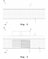
Furthermore, Fig. 2 illustrates an exemplary step of the inventive method in the context of producing a photovoltaic cell assembly. In accordance with said Fig. 2, a foil 1 is provided, for example unrolled, in a provision direction in a continuous manner. Fig. 2 shows the side view 10a of said foil 1 and the view of a surface of said foil 1, exemplarily a top view 10b of said foil 1, further referred to as the second surface of said foil 1.
-
It might be particularly advantageous if the foil 1 is made of a mono-layer thermoplastic material or a multi-layer material such as a three-layer material with a high-temperature melting point core layer such as a basic layer and outer layers (sandwich layers) with a lower melting point than the core layer or the basic layer, respectively. Additionally or alternatively, the provision of the foil 1 may preferably be performed with the aid of an inline conveyor or belt-process.
-
Moreover, according to Fig. 3, in another exemplary step, the foil 1 is cut in accordance with a cutting pattern 2 with the aid of a cutter wheel, laser cutter, or punch stamp 21. It is noted that it might be particularly advantageous if said cutting pattern 2 is configured to cut longitudinal slits extending along the provision direction through the foil 1, such as slits in the form of a finger outline, thereby forming foil-fingers or at least a kind thereof as schematically illustrated in Fig.3. Said cutting pattern 2 is preferably configured such that no parts of the foil 1 come off from the foil 1 as a result of the cutting step. In an example, the foil-fingers do especially not come off as a whole from the foil 1. In this context, said cutting pattern 2 may preferably lead to at least one slit, especially multiple slits, through the foil 1.
-
In another step, as it can be seen from Fig. 4, the multiple slits through the foil 1 are folded open with the aid of a camwheel 22 during unrolling of an electrically conductive wire or electrically conductive wires, respectively, 3 from a roller reel 23. The electrically conductive wires are provided near a surface of the foil 1, for example the first surface of the foil 1 (the first surface being the bottom surface opposite to the top surface 10b in the example of Fig. 4), along the provision direction and they are aligned with the slit pattern. In this context, the slits fold back after electrically conductive wire unrolling. Said electrically conductive wires 3 thereby switch (change position) from the first surface of the foil 1 or the bottom side of the foil 1, respectively, to the second surface of the foil 1 or the top side of the foil 1, respectively, in the region of the cutting pattern 2.
-
Now, with respect to Fig. 5, a further exemplary step is illustrated. In this context, the foil 1 is heated, for example melted, with the aid of hot rollers 24a, 24b at least in the region of the electrically conductive wires, to thereby attach the electrically conductive wires 3 to the foil 1. With respect to the electrically conductive wires 3, it is noted that it can be seen in side view 10a or in top view 10b, respectively, of Fig. 5 that, said electrically conductive wires 3 have switched from the first surface of the foil 1 or the bottom side of the foil 1, respectively, to the second surface of the foil 1 or the top side of the foil 1, in the region of the cutting pattern 2, as described above. As an alternative to or in addition to heating of the foil, the electrically conductive wires 3 may be heated to attach the electrically conductive wires 3 to the foil 1.
-
Said electrically conductive wires 3 on the bottom side of the foil 1, in regions outside the region of the cutting pattern 2, can be seen from Fig. 6 illustrating a view of the first surface of the foil 1 or a bottom view 10c of the foil 1, respectively.
-
In accordance with Fig. 7, in another step, the electrically conductive wires 3 are interrupted or punched or cut, respectively, with the aid of a punch stamp 25 in the region of an edge, especially a first edge region, of the cutting pattern 2 such that respective perforations or punch holes 4 are created through the electrically conductive wires 3 and through the foil 1.
-
In this context, in some embodiments, it might be particularly advantageous if the electrically conductive wires 3 are cut over a length between 0.5 and 4 millimeters, preferably between 2.5 and 3.5 millimeters, more preferably between 2.8 and 3.2 millimeters, most preferably 3 millimeters as illustrated by reference sign 92 in Fig. 8 with respect to the top view 10b and in Fig. 9 with respect to the bottom view 10c of the foil 1.
-
However, the present invention is not limited to these ranges. For example, the electrically conductive wires 3 may be cut over larger or smaller distances than the above-mentioned lengths. Other cutting dimensions may be used, for example depending on the cell design, the cell metallization design, the thickness of the electrically conductive wires, the foil thickness and/or the cutting technique used.
-
Furthermore, according to Fig. 10, in another exemplary step, photovoltaic cells 5a, 5b are placed on the foil 1, in particular on the first surface of the foil 1 in the example shown. A first photovoltaic cell 5a is arranged such that a first edge region of the first photovoltaic cell partly overlaps the perforations 4 formed at the first edge region of the cutting pattern 2, for example such that the corresponding first edge of the first photovoltaic cell extends between 0.5 and 1.5 millimeters, preferably between 0.7 and 1.3 millimeters, more preferably between 0.9 and 1.1 millimeters, most preferably 1 millimeters, beyond the electrically conductive wires 3 especially in the region of the punch holes 4 where the electrically conductive wires 3 are interrupted, as marked by reference sign 94. However, the present invention is not limited to these overlap ranges. In particular, the first photovoltaic cell 5a is arranged such that a second edge region opposite to the first edge region faces away from the region of the cutting pattern 2 such that it does not overlap with the cutting pattern 2. The second edge region of the first photovoltaic cell 5a may overlap an edge region of another cutting pattern, for example another cutting pattern formed earlier (located further in the provision direction), in particular an edge region without punch holes.
-
As it can further be seen from Fig. 10, a second photovoltaic cell 5b is arranged such that a second edge region of the second photovoltaic cell overlaps a second edge region of the cutting pattern 2, wherein the amount of overlap in the provision direction is for example between 0.5 and 1.5 millimeters, preferably between 0.7 and 1.3 millimeters, more preferably between 0.9 and 1.1 millimeters, most preferably 1 millimeters, especially in the region of an edge of the cutting pattern 2 without the punch holes 4 as marked by reference sign 93. However, the present invention is not limited to these overlap ranges. In particular, the second photovoltaic cell 5b is arranged such that a first edge region opposite to the second edge of the second photovoltaic cell 5b faces away from the region of the cutting pattern 2. The first edge region of the second photovoltaic cell 5b may overlap an edge region of another cutting pattern, for example another cutting pattern formed later in the provision direction, in particular an edge region with punch holes.
-
It is noted that it might be particularly advantageous if a major part or a major region of the cutting pattern 2 remains uncovered by any photovoltaic cell.
-
It is further noted that in the context of the above-mentioned first photovoltaic cell 5a and the second photovoltaic cell 5b, photovoltaic cells are basically marked with reference sign 5 in further embodiments as described below.
-
Additionally, reference sign 95 of Fig. 10 marks a distance between the respective cells in the provision direction, in particular a distance between a first edge (at the first edge region) of the first photovoltaic cell 5a and a second edge (at the second edge region) of the second photovoltaic cell 5b. In some embodiments, said distance preferably is equal to between 20 and 200 millimeters, preferably between 40 and 80 millimeters. However, the present invention is not limited thereto. More in general, said distance is preferably equal to the sum of the corresponding cell width and the corresponding intended cell spacing between the first photovoltaic cell 5a and the second photovoltaic cell 5b, if any, especially in the final photovoltaic cell assembly. It is noted that said distance can also be smaller than the cell width to create a small overlap between the first photovoltaic cell 5a and the second photovoltaic cell 5b in the final cell assembly, if desired.
-
With respect to the cell width, it is noted that said cell width may especially be the cell size in the provision direction. With respect to the cell spacing, it is noted that said cell spacing may especially be the distance between the first edge of the first photovoltaic cell 5a and a second edge of the second photovoltaic cell 5b in the provision direction.
-
With respect to Fig. 11, it is noted that said Fig. 11 shows the situation of Fig. 10 in the context of the respective bottom view 10c. Furthermore, especially in the context of Fig. 10 and Fig. 11, Fig. 12 illustrates a step of attaching the photovoltaic cells to the foil 1, in particular to the first surface of the foil 1 in the example shown, by heating the foil in heating areas 6. Accordingly, the foil 1 adheres to the respective full top side or top surface (front side or front surface)of the corresponding cell. Thereby also the electrically conductive wires 3 adhere to the front surface of the corresponding cell in the heating areas 6, such that an electrical front contact (electrical contact to the front side) may be provided thereto. It is noted that it might be particularly advantageous if the heating areas 6 or heated surfaces, respectively, are heated to a temperature between 100 and 120 degrees Celsius.
-
In this context, it might be particularly advantageous if the wires will be indeed physically in contact with the cell, but a final soldered or conductive adhesive cured (if applicable) electrical connection is provided potentially at a later stage, during lamination of the module, as the applied temperature might be higher in the module lamination step.
-
In another step according to Fig. 13, the respective photovoltaic cells 5 and the foil 1 are over-folded. In this context, at least a part of the foil 1 is preferably kept down and held in place by a vacuum 26, exemplarily a bottom-side belt vacuum, especially in regions of the cutting pattern 2 where the electrically conductive wires 3 are attached to the foil. As it can further be seen from Fig. 13, two respective folding lines 81 and 82 being exemplarily perpendicular to the provision direction of the foil 1 are illustrated. In this context, in the example shown, the folding line 81 especially halves the cutting pattern 2, whereas the folding line 82 runs through an edge of the cutting pattern 2, especially through the punch holes 4.
-
In accordance with Fig. 14, also in this context, as marked by reference sign 71, especially the respective foil-fingers with electrically conductive wires 3 are kept down by the vacuum 26, whereas, as marked by reference sign 72, the foil 1 in between the electrically conductive wires 3, especially laterally between the electrically conductive wires 3, preferably in a direction perpendicular to the provision direction, is lifted up. Additionally, as marked by reference sign 73 in Fig. 15, the foil 1 is double-folded between, especially at lateral sides of, the electrically conductive wires 3 at the respective backside of the first photovoltaic cell 5a after over-folding.
-
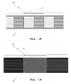
This situation is illustrated in more detail in Fig. 16 and Fig. 17 showing different corresponding sectional views, wherein sections A-A' and B-B' represent sections substantially orthogonal to the provision direction and wherein sections V-V' and W-W' represent sections substantially parallel to the provision direction. Section A-A' corresponds to a location in area 73 where the foil 1 is double-folded at lateral sides of the electrically conductive wires 3, whereas section B-B' corresponds to a location outside area 73. Section V-V' corresponds to locations laterally in between electrically conductive wires 3 and section W-W' corresponds to locations where electrically conductive wires 3 are present. As can be seen in these cross sections, after the folding step, the electrically insulating foil 1 is present between neighboring photovoltaic cells, especially between edges of neighboring photovoltaic cells, such that direct physical contact between neighboring cells is avoided, thereby also avoiding electrical contact between the cells. The foil thus provides electrical edge isolation between neighboring photovoltaic cells. Fig. 18 depicts a corresponding view of the first surface of the foil 1 or a bottom view 10c of the foil 1, as well as a side view 10a, which also emphasizes that the foil 1 is double-folded between the electrically conductive wires 3 as marked by reference sign 73, more in particular in a region at lateral sides of the electrically conductive wires 3.
-
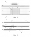
Furthermore, especially after said over-folding according to Fig. 13 to Fig. 18, as illustrated by Fig. 19 in the context of a bottom view 10c and by Fig. 20 in the context of a top view 10b, respectively, the first photovoltaic cell is attached to the foil 1 by heating the foil 1 in a heating area 74. In the example illustrated in Fig. 19 the heating area 74 covers the full area of the first photovoltaic cell such that the foil 1 adheres to the full respective bottom-side (also rear side or back side) cell area of the first photovoltaic cell. Thereby the electrically conductive wires 3 within the heating area 74 also adhere to the bottom side (back side, rear side) of the first photovoltaic cell, thus providing an electrical back contact to the first photovoltaic cell. As the electrically conductive wires 3 are also attached to the front side of the second photovoltaic cell and provide an electrical front contact thereto, in this way an electrical series connection is established between the first photovoltaic cell and the second photovoltaic cell. Fig. 20 shows a corresponding top view 10b and additionally shows corresponding sectional views for further explanation, wherein sections A-A' and B-B' represent sections substantially orthogonal to the provision direction and wherein section X-X' represents a section substantially parallel to the provision direction, more in particular at a location where electrically conductive wires 3 are present.
-
It is an advantage of a method for continuous photovoltaic cell stringing according to embodiments of the first aspect of the present invention that it allows making a practically "endless" string of photovoltaic cells, that can for example be rolled up into a roll from which later on customized strings can be cut, such as for example strings having a custom string length, depending on the envisaged application.
-
In embodiments of the invention, heating area 74 may be limited to only a part of the area of the first photovoltaic cell, such that the foil 1 does not adhere to the full bottom-side area of the first photovoltaic cell but only to a part of the bottom-side area. In an advantageous embodiment the heating area may for example be limited to an area outside the region where the foil 1 is double-folded at the back side of the first photovoltaic cell (i.e. outside the region marked by reference sign 73 in Fig. 15 and Fig. 18). As further explained in more detail, such partial heating offers the possibility of string cutting without loss of cells and without loss of cell active area.
-
String cutting may typically be done in the context of providing electrical connections, such as busbar connections, to a string, wherein electrical connections are to be made to the front side and/or the back side of the string. These electrical connections can for example be made to a photovoltaic cell that is positioned near the location where the string is cut (string cutting area). This requires accessibility to the electrically conductive wires 3 not only at the front side of the photovoltaic cell but also at the back side of the photovoltaic cell. In embodiments of the present invention such required accessibility can advantageously be realized by limiting heating of the foil 1 to an area outside the region where the foil 1 is double-folded at the back side of the first photovoltaic cell.
-
Fig. 21 illustrates details of cell-interconnection in the sense of the invention, wherein the embodiment illustrated in side view 11c is particularly advantageous in the context of string cutting especially avoiding cell loss at the string cutting area, to allow top- or bottom cell interconnection preferably for string bussing.
-
In accordance with said Fig. 21, a side view 11a of the inventive cell assembly or a sectional view along the provision direction of the foil, respectively, is shown, which illustrates the situation after over-folding as explained above. In this context, a corresponding edge isolation is marked by reference sign 61.
-
In addition to this, Fig. 21 depicts a further side view 11b after a heating step especially on the full respective cell as explained above or the situation after a lamination in a module stack, respectively. In this context, reference sign 62 marks the double-folded foil between the wires, whereas reference sign 63 marks the heating area which exemplarily fully heats the respective backside.
-
In further addition to this, Fig. 21 shows a further side view 11c after a heating step, wherein the heating area is limited to only a part, for example about half, of the area of the respective cell such as the first photovoltaic cell 5a according to Fig. 10. In the example shown, the heating area is more in particular limited to an area outside the region where the foil 1 is double-folded at the back side of the first photovoltaic cell, such that the foil and the electrically conductive wires adhere to the back surface of the first photovoltaic cell only in an area where the foil is not double-folded. In this context, reference sign 66 in Fig. 21 marks a non-heating region or non-heating area, wherein the foil and the electrically conductive wires are not laminated to or do not adhere to, respectively, the respective cell backside such as the backside of the first photovoltaic cell 5a of Fig. 10. This advantageously offers the possibility of cutting the string at a location in the non-heating area 66 where the foil and the electrically conductive wires do not adhere to the first photovoltaic cell, without thereby creating inactive cells and without loss of inactive cell area.
-
Reference sign 65 in view 11c of Fig. 21 marks a heating region or heating area, wherein the foil-fingers have been laminated with the electrically conductive wires (in other words: wherein the electrically conductive wires have been attached to the foil) at the backside of the first photovoltaic cell, and wherein a preliminary electrical contact has been established before between the electrically conductive wires and the back side of the first photovoltaic cell.
-
The heating step is followed by a string cutting step, wherein string cutting is preferably done at a location in the non-heating area 66 where the foil and the electrically conductive wires do not adhere to the first photovoltaic cell.
-
After string cutting, the string is separated into a first string 58a (comprising the second photovoltaic cell at an end of the first string) and a second string 58b (comprising the first photovoltaic cell at an end of the second string), as illustrated in Fig. 24. String cutting can for example be done along a direction substantially orthogonal to the provision direction and for example about in the middle of the non-heating region 66 of the first photovoltaic cell, as schematically indicated by the position of a cutter 56 in Fig. 24.
-
It is further shown in Fig. 24 that, after string cutting, the first string 58a further comprises an overhanging part comprising a stack of the foil 1 and at least one electrically conductive wire 3 attached thereto, the at least one electrically conductive wire 3 being electrically connected to the front side of the second photovoltaic cell. This advantageously enables access to the front side electrical contact of the second photovoltaic cell, for example for electrical connection of a busbar in the context of string bussing. String bussing comprises electrical connection of at least one busbar to a string, to thereby enable extraction and collection of an electric current generated by the string upon illumination and/or to further enable electrical connection between at least two strings, for example electrical series connection or electrical parallel connection of strings.
-
In embodiments of the present invention, busbars or busbar ribbons may advantageously be provided at the back side of the strings, such that they are invisible from the front side of the strings and such that they do not cause cell or string shadowing, especially in case of monofacial cells. Providing busbars or busbar ribbons at the back side of the strings further advantageously allows realizing a better cell-to-module surface ratio or aperture as compared to approaches wherein busbars are provided next to the cell strings, for example at an end of the strings. Fig. 25 illustrates an exemplary method for busbar connection, in particular in the context of a first string 58a comprising an overhanging part comprising a stack of the foil 1 and at least one electrically conductive wire 3 attached thereto and electrically connected to the front side of the end cell of the first string 58a. The method illustrated in Fig. 25 comprises attaching a busbar ribbon 8 to the at least one electrically conductive wire 3 in the overhanging part and establishing an electrical contact between the busbar ribbon 8 and the at least one electrically conductive wire 3 (and consequently establishing an electrical contact between the busbar ribbon 8 and the front side of the first string 58a), followed by flipping the overhanging part over the edge of the end cell towards the cell back side. The result after flipping over is illustrated in the bottom part of Fig. 25.
-
It is noted that sections C-C' and D-D' shown in Fig. 25 are sections substantially orthogonal to the provision direction at the location of busbar 8, wherein section C-C' illustrates the situation before flipping over and section D-D' illustrates the situation after flipping over.
-
As a further result of the flipping process, the edge 54 of the end cell of the first string 58a is electrically insulated, especially electrically insulated from the electrically conductive wire 3, by the foil 1. Additionally, in a region 55 where the busbar ribbon 8 is positioned after flipping over, a double electrical insulation (double foil 1) is present between the busbar ribbon 8 (front side electrical contact of the end cell) and the electrically conductive wire 3 at the rear side of the end cell (rear side electrical contact of the end cell). It is a particular advantage of having such a double electrical insulation there in between because of the opposite electrical polarities of both contacts.
-
With respect to the busbars, it is generally noted that busbars may especially be metal-based wires or ribbons or foils, as long as the cross-section is sufficient to avoid too many losses, especially resistive losses. Preferably, the busbars, for example ribbons, may be coated with a low-melting-temperature solder so that a metallurgic bonding of the electrically conductive wires and the busbar is created, for example during the module lamination step. However, a conductive adhesive can be used as well for busbar connection, such as a tape strip or paste. The busbar material can be copper-based or aluminum-based. In the context of CIGS (copper indium gallium (di)selenide) cells, nickel as busbar coating can be considered as well, for example, for direct contact with the cell backside.
-
With respect to establishing electrical contacts such as the above-mentioned establishing the electrical contact between the busbar ribbon 8 and the at least one electrically conductive wire 3, it is noted that this can exemplarily be done by soldering, preferably with the aid of low-melting-temperature solder, push contact, preferably with nickel coating, or conductive adhesive such as tape or paste.
-
Furthermore, Fig. 24 shows that, after string cutting, at the rear side of the end cell of the second string 58b, different regions 57a, 57b and 57c can be distinguished:
- in a first region 57a, at a first side of the cutting location, the rear side of the end cell is partially covered by the foil 1, without any electrically conductive wires;
- in a second region 57b, at another side of the cutting location, the rear side of the cell is covered by a structure comprising the foil 1 and electrically conductive wires 3 but without an electrical contact between the wires and the cell, as this second region 57b is part of non-heating region 66, outside heating region;
- in a third region 57c (corresponding to heating region 65), the rear side of the cell is partially covered by a structure comprising the foil 1 and electrically conductive wires 3, the wires being attached to the rear side of the cell and providing a rear side electrical contact thereto, as a result of the heating step in heating region 65.
-
This advantageously enables access to the back side electrical contact of the first photovoltaic cell, for example for electrical connection of a busbar in the context of string bussing.
-
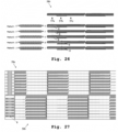
Fig. 26 illustrates exemplary methods for busbar connection, in particular in the context of a second string 58b.
- In a first exemplary method (method 1 in Fig. 26) a busbar 8 is electrically connected to the rear side of the first photovoltaic cell in first region 57a. This method comprises folding the foil 1 from region 57a away from the photovoltaic cell to thereby uncover and expose the rear side of the photovoltaic cell in the entire first region 57a, next providing a busbar 8 on the rear surface of the photovoltaic cell in first region 57a and afterwards folding back the foil 1 towards the rear side of the photovoltaic cell, over the busbar. It is noted that alternatively this method advantageously allows to pre-tack the busbar, in particular to attach the busbar to the part of the foil 1 folded away from region 57a as explained above before folding back the foil, preferably by means of the foil remainders, in a pre-lamination heating step.
- In a second exemplary method (method 2 in Fig. 26) a busbar 8 is electrically connected to the rear side of the first photovoltaic cell in first region 57a. This method comprises removing the foil 1 from region 57a, for example by cutting it away and thus removing it from the second string 58, to thereby uncover and expose the rear side of the photovoltaic cell in the entire first region 57a. Next a busbar 8 is provided on the rear surface of the photovoltaic cell in first region 57a and an electrical connection is established.
- In a third exemplary method (method 3 in Fig. 26) a busbar 8 is electrically connected to the rear side of the first photovoltaic cell in first region 57a. This method comprises providing the busbar 8 over the foil 1. As described above, in the first region 57a only a part of the photovoltaic cell rear side is covered by the foil and another part is uncovered (i.e. exposed). According to this third exemplary method, an electrical contact is established between the busbar and the rear side contact of the first photovoltaic cell in the uncovered (exposed) parts. Advantageously, the busbar can be pre-tacked to the cell backside, in particular attached to the cell backside before establishing an electrical contact thereto.
- In a fourth exemplary method (method 4 in Fig. 26) a busbar 8 is electrically connected to the rear side of the first photovoltaic cell in second region 57b. This method comprises folding the foil 1 and the wires 3 from the entire second region 57b away from the photovoltaic cell to thereby uncover and expose the rear side of the photovoltaic cell in the entire second region 57b, next providing a busbar 8 on the rear surface of the photovoltaic cell in second region 57b and afterwards folding back the foil 1 and the wires 3 towards the rear side of the photovoltaic cell, over the busbar. An electrical contact can then be established directly between the rear side of the photovoltaic cell and the ribbon 8 and/or between the folded-back wires 3 (rear side electrical contact of the photovoltaic cell) and the busbar 8. This method might be particularly advantageous if the ribbon coating (solder, metal coating or conductive adhesive) doesn't allow a good contact with the cell surface, or would create too much (thermal) stress on the interconnects between the busbar and the solar cell would be.
- In a fifth exemplary method (method 5 in Fig, 26) a busbar 8 is electrically connected to the rear side of the first photovoltaic cell in second region 57b. This method comprises folding the foil 1 and the wires 3 away from the second region 57b in regions where wires are present and leaving the regions in between the wires (i.e. at lateral sides of the wires, where the foil is double-folded) covered by a single layer of foil, i.e. folding away only one layer of foil in the regions where the foil is double-folded, such that part of the photovoltaic cell rear side remains covered by the foil and another part is uncovered. Next a busbar 8 is provided at the rear side of the photovoltaic cell (over the foil 1 partially covering the rear side. An electrical contact can then established between the busbar and the rear side contact of the first photovoltaic cell in the uncovered (exposed) parts and / or between the folded-back wires 3 and the busbar 8.
-
It is noted that it might be particularly advantageous if the method for continuous cell stringing enables access to the respective top- or bottom side cell contact of the photovoltaic cells near the cell string cutting area. This can especially be achieved with the aid of the above-mentioned partial lamination of the film at the back as explained in the context of the side view 11c of Fig. 21, allowing the string to be cut at the back of a cell and still have access to the cell contact at the bottom of that cell, and the cell contact at the top of the neighboring cell of the other part of the cut string. Advantageously, cell loss or creation of inactive cells, respectively, on the ends of the cut strings is avoided.
-
Now, with respect to Fig. 22, exemplary busbar contacting and finishing or busbar ribbon placement, respectively, is shown in the context of string cutting and bussing of strings in the sense of the invention. Said busbars or busbar ribbons may advantageously be provided at the respective backside of the cells (back side of the strings), such that they are invisible from the front side of the strings and such that they do not cause cell or string shadowing. According to said Fig. 22, part of a first string 59a is shown, in particular an end cell of a first string 59a, wherein a top cell contact of the end cell is connected to a string busbar. In this context, the respective string busbar especially for string bussing is marked with reference sign 8. Additionally, said first string 59a comprises in insulated cell edge 54 and a region 55 being double insulated especially with opposite polarities.
-
Furthermore, Fig. 22 further depicts a second string 59b comprising bottom cell contact to the string busbar 8 in the context of a case, wherein a foil cut was done as marked by reference sign 51, and in the context of a case, wherein a foil end was not laminated as explained in the context of view 11 c of Fig. 21,so can be folded back to add busbar ribbon as marked by reference sign 52. With respect to busbar contacting and finishing, it is generally noted that said contacting can be done at the respective backside of the foil. In this context, the respective cell backside between foil fingers can be contacted.
-
Among the exemplary methods described above in the context of Fig. 26, methods 1, 2 and 4 advantageously may lead to, for instance, a better contact between the busbar 8 and the rear side of the first photovoltaic cell as compared to methods 3 and 5. As a further alternative, all foil fingers can be cut away especially for direct access to the respective cell backside.
-
Now, with respect to Fig. 23, a further exemplary step in the context of the inventive method is shown, wherein the heating area 75 is configured such that the foil-fingers with the electrically conductive wires adhere to the respective cell backside only in a part of the cell area, for example about half of the area of the cell. Additionally, for further illustration, said Fig. 23 also depicts different corresponding sectional views.
-
Furthermore, Fig. 24 illustrates exemplary cutting of a cell string at a desired place, especially at the backside of the respective cell in a non-laminated area of the foil. In this context, especially for string cutting, the cutter 56 is used. It is noted that it might be particularly advantageous if the respective cutting line is in the middle of the corresponding non-laminated backside area. Advantageously, only the foil and electrically conductive wires are cut, not the cell. Additionally, reference sign 57c marks a region, wherein the foil-fingers with electrically conductive wires are laminated to the backside of the respective cell.
-
As it can further be seen form Fig. 24, the respective string parts can be separated into a first string 58a and a second string 58b.
-
In accordance with Fig. 25, within the scope of busbar contacting and finishing, foil flipping can be applied with respect to the first string 58a especially comprising top cell contact to the string busbar.
-
Moreover, Fig. 26 illustrates different methods in the context of foil flipping with respect to the second string 58b especially comprising backside cell contact to the string busbar.
-
As it can further be seen from Fig. 27 referring to an exemplary cell string interconnection via busbars 8, a backside view of the first string 58a and of the second string 58b in the context of method 1 of Fig. 26 is illustrated, wherein the front side contact of the string 58a is folded to the corresponding backside.
-
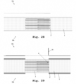
Furthermore, Fig. 28 illustrates a further exemplary step, especially before electrically conductive wire interruption, preferably in the context of diode implementation, in particular bypass diode implementation. In this context, it might be particularly advantageous if the cutting pattern is changed as marked by reference sign 2'. As it can be seen, said changed cutting pattern 2' is based on the above-mentioned cutting pattern 2, wherein the foil-fingers are especially not fully cut in the region of the corresponding fingertips.
-
In another exemplary step, in accordance with Fig. 29, with the aid of a punch cutter 28, punch holes 4 or perforations, respectively, are made through the electrically conductive wires 3 and through the foil 1, especially in the region of the fingertips of the foil-fingers cut into the foil 1, thereby preferably interrupting the electrically conductive wires 3.
-
According to Fig. 30, in another exemplary step within the scope of diode implementation, especially after the step of arranging the at least two photovoltaic cells on the foil, whereas the foil 1 may be kept down with the aid of a vacuum 26, especially a bottom-side belt vacuum, preferably in the region of the changed cutting pattern 2', a bypass diode strip 9, especially a thin-film diode strip with top and bottom contact, is placed preferably in the region of an edge of the changed cutting pattern 2' exemplarily without punch holes 4, i.e. in the second edge region of the cutting pattern.
-
Moreover, in a further exemplary step, especially after diode strip placing, over-folding may be performed in an analogous manner to the over-folding as already described above. During over-folding a part of the foil 1 is kept down and held in place with the aid of a vacuum 26, especially a bottom-side belt vacuum, preferably in the regions of the changed cutting pattern 2' where the wires 3 are attached to the foil 1. In this context, the corresponding folding lines are marked by reference sign 31 of Fig. 31.
-
In addition to this, reference sign 32 of Fig. 32 marks areas, wherein the foil with electrically conductive wires is kept down by the vacuum 26, whereas reference sign 33 of Fig. 32 marks areas, wherein the foil in between the electrically conductive wires is lifted up.
-
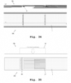
Furthermore, for further illustration, Fig. 33 or Fig. 34, respectively, show the situation especially after said over-folding exemplarily within the scope of simultaneously top contacting of the diode or diode strip. Additionally, Fig. 34 illustrates a sectional view comprising said diode strip 9 along the provision direction.
-
Now, with aid of Fig. 35 to Fig. 43, an additional option to create flexible and at least partially stretchable cell strings in the sense of the invention is illustrated. In this context, it is noted that said additional option might be particularly advantageous in the context of avoiding and compensating for undesired effects, such as stress effects, that may be caused, for example during and/or after manufacturing, by differences in coefficient of thermal expansion between different materials in a cell and/or a string and/or in a module.
-
In accordance with Fig. 35, an adapted cutting pattern 2" is applied to the foil 1 with the aid of a cutter wheel or punch stamp 35.
-
Said adapted cutting pattern 2'' comprises a region 99 being configured such that the resulting foil structure after stretching resembles that of an expanded sheet, exemplarily like an expanded metal sheet, as marked by reference sign 36 of Fig. 36. As it can also be seen from said Fig. 36, foil stretching is especially performed in and/or against the provision direction. Said foil stretching may preferably lead to local expanded foil areas.
-
In this context, it might be particularly advantageous if the foil in the expanded foil region is elastically (so not plastically) deformed during stretching, so that it can take its original shape after later releasing of the foil.
-
Moreover, according to Fig. 37, in another step, especially after said foil stretching, foil lifting and addition of electrically conductive wires 3 is performed in an analogous manner to one as already described above without stretching. In this context, a camwheel 37 is exemplarily used for folding open the foil at the location of the slits of adapted cutting pattern 2'', whereas a roller reel 38 is exemplarily used for electrically conductive wire unrolling.
-
In accordance with Fig. 38, in another step, the foil 1 is heated, for example melted on the electrically conductive wires 3, preferably not melted, but just heated to make it sticky such that the electrically conductive wires 3 are attached to the foil 1, with the aid of hot rollers 24a, 24b. In addition to this, reference sign 39 of said Fig. 38 marks areas, wherein the electrically conductive wires are laminated at the respective bottom side of the expanded foil region.
-
In another step according to Fig. 39, by analogy with Fig. 7, electrically conductive wire interruption and foil punching are performed with the aid of a punch stamp 25.
-
Furthermore, by analogy with Fig. 10, cell lamination can be performed in another step according to Fig. 40, especially after said wire interruption.
-
Moreover, especially by analogy with the over-folding as already described above, cell/foil over-folding can be performed preferably after said cell lamination of Fig. 40, the result of which is illustrated by Fig. 41.
-
Especially after over-folding, in accordance with Fig. 42, foil detensioning or foil release, respectively, is performed. In this context, reference sign 42 marks areas, wherein the electrically conductive wire section at the previously expanded foil section folds or straps together, respectively. Accordingly, the foil relaxes and returns to its original shape.
-
Furthermore, in addition to this, Fig. 43 illustrates a view of the first surface with respect to the foil 1 or a bottom view 10c, respectively.
-
Finally, especially with respect to the inventive method having been illustrated in the context of producing a photovoltaic cell assembly in accordance with Fig. 2 to Fig. 43, the major character of the inventive method is summarized in a nutshell in the following example. In this context, the method can especially be seen as a continuous process, for instance, with a vacuum conveyer. Firstly, the foil is unrolled on a belt. Said foil may be a foil with a high melting point and an adhesive layer with a low melting point on both sides. Then, the foil is perforated. For instance, a cutting wheel presses a cutting pattern into the foil. Advantageously, there is no interruption in the speed of the conveyor belt.
-
Furthermore, the respective slit is lifted by, for example, a cam wheel. Additionally, the at least one electrically conductive wire, especially multiple electrically conductive wires, are unrolled, preferably parallel to the progress of the conveyor belt, from the underside of the foil. As the foil progresses, the slit opening is folded back. Moreover, the electrically conductive wires adhere to the foil by running the conveyor with the foil and wires through a set of hot pressure rollers. Then, the electrically conductive wires in the foil are interrupted, for instance, with the aid of a punching stamp.
-
Furthermore, placement of the cells on one side and adhesion to the foil are performed, for instance, with the aid of a short heating step about 100 degrees Celsius to adhere the cells to the foil, preferably with one cell spacing and an additional spacing between cells, if needed. Moreover, folding or over-folding, respectively, of cell and foil is performed. In this context, the foil structure preferably keeps the electrically conductive wire flat on the conveyor belt during the folding process, and contactable from the top. The cell position may especially be secured by a short heating step to about 100 degrees Celsius.
-
Advantageously, as it can be seen, the invention combines foil, electrically conductive wires, and cells in one process, reducing alignment steps to an absolute minimum, in a continuous moving process on a conveyor belt. In addition, the invention allows the addition of diodes per cell or a series of cells, and solar cell edge protection to prevent short circuits or electrical shunts at the cell edge with the electrically conductive wires running from cell to cell.
-
With general respect to Fig. 2 to Fig. 43, it is noted that the figures especially show a process with cell placement on the bottom and electrically conductive wire placement on the top, but this process can be reversed if it is feasible/convenient.
-
The process also allows for the integration of bypass diodes between two adjacent cells. Important to note is the ability to protect the edges of the cells by the foil, which is determined by the cutting pattern during the embossing step. During over-folding, the alignment of the cell is advantageously determined by the cutting pattern, which is already correctly positioned relative to the cells during the cell placement step.
-
Furthermore, the figures also detail the possibility to cut the continuous cell string, with the ability to gain access to both polarities of the outer cells of the cut string and potential schemes for the placement of the busbars. Further advantageously, as already explained above, the invention also allows for the creation of stretchable cell strings.
-
While various embodiments of the present invention have been described above, it should be understood that they have been presented by way of example only, and not limitation. Numerous changes to the disclosed embodiments can be made in accordance with the disclosure herein without departing from the spirit or scope of the invention. Thus, the breadth and scope of the present invention should not be limited by any of the above described embodiments. Rather, the scope of the invention should be defined in accordance with the following claims and their equivalents.
-
Although the invention has been illustrated and described with respect to one or more implementations, equivalent alterations and modifications will occur to others skilled in the art upon the reading and understanding of this specification and the annexed drawings. In addition, while a particular feature of the invention may have been disclosed with respect to only one of several implementations, such feature may be combined with one or more other features of the other implementations as may be desired and advantageous for any given or particular application.