EP4325523A1 - Uv reaction apparatus for treating waste liquid caused by system decontamination in nuclear power plant - Google Patents
Uv reaction apparatus for treating waste liquid caused by system decontamination in nuclear power plant Download PDFInfo
- Publication number
- EP4325523A1 EP4325523A1 EP22788261.0A EP22788261A EP4325523A1 EP 4325523 A1 EP4325523 A1 EP 4325523A1 EP 22788261 A EP22788261 A EP 22788261A EP 4325523 A1 EP4325523 A1 EP 4325523A1
- Authority
- EP
- European Patent Office
- Prior art keywords
- unit
- waste liquid
- organic waste
- reaction apparatus
- input
- Prior art date
- Legal status (The legal status is an assumption and is not a legal conclusion. Google has not performed a legal analysis and makes no representation as to the accuracy of the status listed.)
- Pending
Links
- 239000007788 liquid Substances 0.000 title claims abstract description 90
- 238000006243 chemical reaction Methods 0.000 title claims abstract description 39
- 239000002699 waste material Substances 0.000 title claims abstract description 29
- 238000005202 decontamination Methods 0.000 title claims abstract description 17
- 230000003588 decontaminative effect Effects 0.000 title claims abstract description 17
- 239000010815 organic waste Substances 0.000 claims abstract description 61
- 238000009281 ultraviolet germicidal irradiation Methods 0.000 claims abstract description 29
- 230000001678 irradiating effect Effects 0.000 claims abstract description 6
- 238000005192 partition Methods 0.000 claims description 10
- OKTJSMMVPCPJKN-UHFFFAOYSA-N Carbon Chemical compound [C] OKTJSMMVPCPJKN-UHFFFAOYSA-N 0.000 claims description 4
- 229910052799 carbon Inorganic materials 0.000 claims description 4
- 238000000926 separation method Methods 0.000 claims description 2
- 238000000354 decomposition reaction Methods 0.000 description 15
- 238000000034 method Methods 0.000 description 9
- 238000010586 diagram Methods 0.000 description 6
- 238000004904 shortening Methods 0.000 description 4
- 230000008901 benefit Effects 0.000 description 2
- 150000007524 organic acids Chemical class 0.000 description 2
- 238000005086 pumping Methods 0.000 description 2
- 230000000694 effects Effects 0.000 description 1
- 238000001914 filtration Methods 0.000 description 1
- 238000005070 sampling Methods 0.000 description 1
- 239000013589 supplement Substances 0.000 description 1
- 230000001502 supplementing effect Effects 0.000 description 1
- 230000009885 systemic effect Effects 0.000 description 1
Images

Classifications
-
- C—CHEMISTRY; METALLURGY
- C02—TREATMENT OF WATER, WASTE WATER, SEWAGE, OR SLUDGE
- C02F—TREATMENT OF WATER, WASTE WATER, SEWAGE, OR SLUDGE
- C02F1/00—Treatment of water, waste water, or sewage
- C02F1/30—Treatment of water, waste water, or sewage by irradiation
- C02F1/32—Treatment of water, waste water, or sewage by irradiation with ultraviolet light
- C02F1/325—Irradiation devices or lamp constructions
-
- G—PHYSICS
- G21—NUCLEAR PHYSICS; NUCLEAR ENGINEERING
- G21F—PROTECTION AGAINST X-RADIATION, GAMMA RADIATION, CORPUSCULAR RADIATION OR PARTICLE BOMBARDMENT; TREATING RADIOACTIVELY CONTAMINATED MATERIAL; DECONTAMINATION ARRANGEMENTS THEREFOR
- G21F9/00—Treating radioactively contaminated material; Decontamination arrangements therefor
- G21F9/04—Treating liquids
- G21F9/06—Processing
-
- C—CHEMISTRY; METALLURGY
- C02—TREATMENT OF WATER, WASTE WATER, SEWAGE, OR SLUDGE
- C02F—TREATMENT OF WATER, WASTE WATER, SEWAGE, OR SLUDGE
- C02F1/00—Treatment of water, waste water, or sewage
- C02F1/001—Processes for the treatment of water whereby the filtration technique is of importance
- C02F1/004—Processes for the treatment of water whereby the filtration technique is of importance using large scale industrial sized filters
-
- C—CHEMISTRY; METALLURGY
- C02—TREATMENT OF WATER, WASTE WATER, SEWAGE, OR SLUDGE
- C02F—TREATMENT OF WATER, WASTE WATER, SEWAGE, OR SLUDGE
- C02F1/00—Treatment of water, waste water, or sewage
- C02F1/008—Control or steering systems not provided for elsewhere in subclass C02F
-
- C—CHEMISTRY; METALLURGY
- C02—TREATMENT OF WATER, WASTE WATER, SEWAGE, OR SLUDGE
- C02F—TREATMENT OF WATER, WASTE WATER, SEWAGE, OR SLUDGE
- C02F2101/00—Nature of the contaminant
- C02F2101/006—Radioactive compounds
-
- C—CHEMISTRY; METALLURGY
- C02—TREATMENT OF WATER, WASTE WATER, SEWAGE, OR SLUDGE
- C02F—TREATMENT OF WATER, WASTE WATER, SEWAGE, OR SLUDGE
- C02F2101/00—Nature of the contaminant
- C02F2101/30—Organic compounds
-
- C—CHEMISTRY; METALLURGY
- C02—TREATMENT OF WATER, WASTE WATER, SEWAGE, OR SLUDGE
- C02F—TREATMENT OF WATER, WASTE WATER, SEWAGE, OR SLUDGE
- C02F2103/00—Nature of the water, waste water, sewage or sludge to be treated
- C02F2103/34—Nature of the water, waste water, sewage or sludge to be treated from industrial activities not provided for in groups C02F2103/12 - C02F2103/32
-
- C—CHEMISTRY; METALLURGY
- C02—TREATMENT OF WATER, WASTE WATER, SEWAGE, OR SLUDGE
- C02F—TREATMENT OF WATER, WASTE WATER, SEWAGE, OR SLUDGE
- C02F2201/00—Apparatus for treatment of water, waste water or sewage
- C02F2201/32—Details relating to UV-irradiation devices
- C02F2201/322—Lamp arrangement
-
- C—CHEMISTRY; METALLURGY
- C02—TREATMENT OF WATER, WASTE WATER, SEWAGE, OR SLUDGE
- C02F—TREATMENT OF WATER, WASTE WATER, SEWAGE, OR SLUDGE
- C02F2201/00—Apparatus for treatment of water, waste water or sewage
- C02F2201/32—Details relating to UV-irradiation devices
- C02F2201/322—Lamp arrangement
- C02F2201/3227—Units with two or more lamps
-
- C—CHEMISTRY; METALLURGY
- C02—TREATMENT OF WATER, WASTE WATER, SEWAGE, OR SLUDGE
- C02F—TREATMENT OF WATER, WASTE WATER, SEWAGE, OR SLUDGE
- C02F2201/00—Apparatus for treatment of water, waste water or sewage
- C02F2201/32—Details relating to UV-irradiation devices
- C02F2201/328—Having flow diverters (baffles)
-
- C—CHEMISTRY; METALLURGY
- C02—TREATMENT OF WATER, WASTE WATER, SEWAGE, OR SLUDGE
- C02F—TREATMENT OF WATER, WASTE WATER, SEWAGE, OR SLUDGE
- C02F2209/00—Controlling or monitoring parameters in water treatment
- C02F2209/001—Upstream control, i.e. monitoring for predictive control
-
- C—CHEMISTRY; METALLURGY
- C02—TREATMENT OF WATER, WASTE WATER, SEWAGE, OR SLUDGE
- C02F—TREATMENT OF WATER, WASTE WATER, SEWAGE, OR SLUDGE
- C02F2209/00—Controlling or monitoring parameters in water treatment
- C02F2209/003—Downstream control, i.e. outlet monitoring, e.g. to check the treating agents, such as halogens or ozone, leaving the process
-
- C—CHEMISTRY; METALLURGY
- C02—TREATMENT OF WATER, WASTE WATER, SEWAGE, OR SLUDGE
- C02F—TREATMENT OF WATER, WASTE WATER, SEWAGE, OR SLUDGE
- C02F2209/00—Controlling or monitoring parameters in water treatment
- C02F2209/20—Total organic carbon [TOC]
-
- C—CHEMISTRY; METALLURGY
- C02—TREATMENT OF WATER, WASTE WATER, SEWAGE, OR SLUDGE
- C02F—TREATMENT OF WATER, WASTE WATER, SEWAGE, OR SLUDGE
- C02F2301/00—General aspects of water treatment
- C02F2301/04—Flow arrangements
- C02F2301/046—Recirculation with an external loop
Definitions
- the present invention relates to a UV reaction apparatus for treating waste liquid caused by system decontamination in a nuclear power plant.
- waste liquid generated after system decontamination in a nuclear power plant flows into the UV reaction apparatus, which is a waste liquid decomposition and treatment apparatus.
- the organic waste liquid passed through the filter passes through the UV reaction apparatus, and after passing through, moves to the buffer tank to remove CO 2 gas.
- TOC analysis is performed by sampling at the front and rear ends of the UV reaction apparatus.
- the problem to be solved by the present invention is that since the contact time is short as the organic waste liquid passes vertically or horizontally into the reaction apparatus, the total waste liquid decomposition time increases, and in order to solve this problem, it is to provide a UV reaction apparatus for treating waste liquid caused by system decontamination in a nuclear power plant.
- a UV reaction apparatus for treating waste liquid caused by system decontamination in a nuclear power plant capable of improving waste liquid decomposition performance by shortening the waste liquid decomposition time by increasing the UV lamp contact time.
- a UV reaction apparatus for treating waste liquid caused by system decontamination in a nuclear power plant for shortening the waste liquid decomposition process time through the process, in which, as the waste liquid decomposed by more than 90% by the circulation process between the buffer tank and the UV reaction apparatus flows into the system, the organic waste liquid of the system is diluted and the concentration is lowered.
- UV reaction apparatus for treating waste liquid caused by system decontamination in a nuclear power plant capable of improving the decomposition rate by increasing the contact time and the contact frequency to supplement the limitations of the existing organic acid decomposition process.
- a UV reaction apparatus for treating waste liquid caused by system decontamination in a nuclear power plant comprises a UV irradiation unit for irradiating UV light as a bar-shaped body; and a transit unit provided on the UV irradiation unit and for allowing filled organic waste liquid to be irradiated with the UV light, wherein the transit unit comprises, an input unit, into which the organic waste liquid is input, a discharge unit, through which the organic waste liquid is discharged, and an intermediate unit located between the input unit and the discharge unit and provided in a coil shape in a height direction of an outer circumferential surface of the UV irradiation unit.
- At least a length value of the intermediate unit has a larger value than a length value of the UV irradiation unit so that time, during which the organic waste liquid passing through the intermediate unit is exposed to the UV light, is extended.
- a UV reaction apparatus for treating waste liquid caused by system decontamination in a nuclear power plant comprises a UV irradiation unit for irradiating UV light as a bar-shaped body; and a transit unit accommodating the UV irradiation unit therein, and for passing organic waste liquid to be irradiated with the UV light, wherein the transit unit comprises, an input unit, into which the organic waste liquid is input, a discharge unit, through which the organic waste liquid is discharged, and an intermediate unit located between the input unit and the discharge unit, and in which the UV irradiation unit is located.
- the UV irradiation unit is provided in plural so as to be adjacent to each other, a plurality of piece-shaped partition wall units are provided on an inner circumferential surface of the intermediate unit, and the partition wall unit allows the organic waste liquid input on an inner circumferential surface of the intermediate unit to stagnate in the intermediate unit so that time, during which the organic waste liquid is exposed to the UV light, is extended.
- the UV reaction apparatus further comprises a buffer tank for performing circulation operation with the transit unit, wherein the buffer tank, into which the organic waste liquid irradiated with the UV light is input, and inputs the input organic waste liquid into the transit unit to increase frequency of exposure of the organic waste liquid to the UV light on the transit unit.
- the UV reaction apparatus further comprises an analysis unit for obtaining a total organic carbon (TOC) analysis value of the organic waste liquid on the transit unit, wherein the circulation operation is repeated until the analysis value reaches a preset value.
- TOC total organic carbon
- the UV reaction apparatus further comprises a first flow path, a second flow path connected at the first flow path and for supplying the organic waste liquid to a filter unit, a filter unit for filtering the organic waste liquid supplied through the second flow path, and supplying the filtered organic waste liquid to the transit unit, a third flow path for supplying the organic waste liquid from the filter unit to the transit unit, a fourth flow path for supplying the organic waste liquid from the transit unit to the buffer tank, a fifth flow path for supplying the organic waste liquid from the buffer tank to the transit unit, a sixth flow path for supplying the organic waste liquid from the buffer tank to the first flow path, and a pump for pumping the organic waste liquid supplied from the buffer tank to the transit unit.
- the present invention there is a problem that the total waste liquid decomposition time increases due to the short contact time as the organic waste liquid passes vertically or horizontally into the reaction apparatus, and it is possible to provide a UV reaction apparatus for treating waste liquid caused by system decontamination in a nuclear power plant in order to solve this problem.
- UV reaction apparatus for treating waste liquid caused by systemic decontamination in a nuclear power plant capable of improving the decomposition rate by supplementing the limitations of the existing organic acid decomposition process by increasing the contact time and the contact frequency.
- FIG. 1 is a diagram showing a UV reaction apparatus according to an embodiment of the present invention.
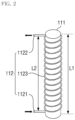
- FIG. 2 is a diagram showing the configuration according to FIG. 1 .
- a UV reaction apparatus for treating waste liquid caused by system decontamination in a nuclear power plant may comprise a UV reaction apparatus 110 and a buffer tank 120.
- the UV reaction apparatus 110 may include a UV irradiation unit 111, a transit unit 112, and the transit unit 112 may include an input unit 1121, a discharge unit 1122, and an intermediate unit 1123.
- the UV irradiation unit 111 may irradiate UV light as a bar-shaped body.
- the transit unit 112 may be provided on the UV irradiation unit 111.
- the transit unit is for irradiating the filled organic waste liquid with the UV light.
- the input unit 1121 of the transit unit 112 may allow the organic waste liquid to be input.
- the discharge unit 1122 of the transit unit 112 may allow the organic waste liquid to be discharged.
- the intermediate unit 1123 of the transit unit 112 may be located between the input unit 1121 and the discharge unit 1122.
- the intermediate unit 1123 may be provided in a coil shape in a height direction of an outer circumferential surface of the UV irradiation unit 111.
- the intermediate unit 1123 may have a length value greater than at least the length value of the UV irradiation unit 111. Through this, the exposure time of the organic waste liquid passing through the intermediate unit 1123 to the UV light can be extended.
- partition wall unit 1231 is designed so that the width of the arrangement becomes narrower from the input unit to the discharge unit, and this is to consider the pressure when the flow rate is introduced from the input unit.
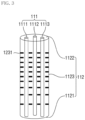
- FIG. 3 is a diagram showing another embodiment of the configuration according to FIG. 1 .
- description will be made based on the above-described embodiment, but focusing on technical features.
- a UV reaction apparatus may comprise a UV irradiation unit 111, a transit unit 112, and a buffer tank 120, similarly to the above embodiment.
- the transit unit 112 may comprise an input unit 1121, a discharge unit 1122, an intermediate unit 1123, a first flow path P1, a second flow path P2, a third flow path P3, a fourth flow path P4, a fifth flow path P5 and a sixth flow path P6.
- the transit unit 112 may accommodate the UV irradiation unit 111 therein.
- the transit unit 112 is to pass through the organic waste liquid to be irradiated with the UV light.
- the intermediate unit 1123 of the transit unit 112 may be located between the input unit 1121 and the discharge unit 1122.
- the UV irradiation unit 111 may be located in the intermediate unit 1123.
- the UV irradiation unit 111 may be provided in plural so as to be adjacent to each other.
- the intermediate unit 1123 may be provided with a plurality of piece-shaped partition wall units 1231 on the inner circumferential surface.
- the partition wall unit 1231 may allow the organic waste liquid input on the inner circumferential surface of the intermediate unit 1123 to stagnate in the intermediate unit 1123. Accordingly, the time, during which the organic waste liquid is exposed to the UV light, can be extended.
- the partition wall unit 1231 may be arranged so that the separation state of the partition wall unit 1231 gradually narrows from the input unit 1121 side toward the discharge unit 1122 side. This is to consider the pressure when the flow rate is introduced from the input unit.
- the buffer tank 120 may perform circulation operation with the transit unit 112.
- the buffer tank 120 may be input with the organic waste liquid irradiated with the UV light.
- the buffer tank 120 may increase the frequency of exposure of the organic waste liquid to the UV light on the transit unit 112 by inputting the input organic waste liquid into the transit unit 112.
- the analysis unit 115 may obtain a total organic carbon (TOC) analysis value of the organic waste liquid on the transit unit 112. Here, the circulation operation may be repeated until the analysis value reaches a preset value.
- TOC total organic carbon
- the total organic carbon (TOC) analysis through the analysis unit 115 is provided at the front and rear ends of the UV reactor 110, the UV irradiation unit 111, and the transit unit 112 to perform analysis, respectively.
- the analysis unit 115 may be provided on the input unit 1121 side and the discharge unit 1122 side, respectively, to perform analysis.
- the first flow path P1 may communicate with the filter unit 130 through the second flow path P2 and may communicate with the buffer tank 120.
- the filter unit 130 may filter the organic waste liquid supplied from the first flow path P1.
- the filter unit 130 may supply the filtered organic waste liquid to the transit unit 112.
- the third flow path P3 may supply the organic waste liquid from the filter unit 130 to the transit unit 112.
- the fourth flow path P4 may supply the organic waste liquid to the transit unit 112 and the buffer tank 120.
- the fifth flow path P5 may supply the organic waste liquid from the buffer tank 120 to the transit unit 112.
- the sixth flow path P6 may supply the organic waste liquid from the buffer tank 120 to the first flow path P1.
- the pump PM is for pumping the organic waste liquid supplied from the buffer tank 120 to the transit unit 112.
Landscapes
- Engineering & Computer Science (AREA)
- Water Supply & Treatment (AREA)
- Life Sciences & Earth Sciences (AREA)
- Hydrology & Water Resources (AREA)
- Toxicology (AREA)
- Environmental & Geological Engineering (AREA)
- Health & Medical Sciences (AREA)
- Chemical & Material Sciences (AREA)
- Organic Chemistry (AREA)
- Physics & Mathematics (AREA)
- General Engineering & Computer Science (AREA)
- High Energy & Nuclear Physics (AREA)
- Physical Water Treatments (AREA)
Abstract
Description
- This application claims the benefit of
Korean Patent Application No. 10-2021-0048956, filed on April 15, 2021 - The present invention relates to a UV reaction apparatus for treating waste liquid caused by system decontamination in a nuclear power plant.
- In the case of waste liquid generated after system decontamination in a nuclear power plant, it flows into the UV reaction apparatus, which is a waste liquid decomposition and treatment apparatus. The organic waste liquid passed through the filter passes through the UV reaction apparatus, and after passing through, moves to the buffer tank to remove CO2 gas. At this time, TOC analysis is performed by sampling at the front and rear ends of the UV reaction apparatus. In order to improve the decomposition of the organic waste liquid, it is necessary to increase the contact frequency or the contact time in the UV reaction apparatus of the waste liquid decomposition and treatment device.
- The problem to be solved by the present invention is that since the contact time is short as the organic waste liquid passes vertically or horizontally into the reaction apparatus, the total waste liquid decomposition time increases, and in order to solve this problem, it is to provide a UV reaction apparatus for treating waste liquid caused by system decontamination in a nuclear power plant.
- In addition, it is to provide a UV reaction apparatus for treating waste liquid caused by system decontamination in a nuclear power plant capable of improving waste liquid decomposition performance by shortening the waste liquid decomposition time by increasing the UV lamp contact time.
- In addition, it is to provide a UV reaction apparatus for treating waste liquid caused by system decontamination in a nuclear power plant for shortening the waste liquid decomposition process time through the process, in which, as the waste liquid decomposed by more than 90% by the circulation process between the buffer tank and the UV reaction apparatus flows into the system, the organic waste liquid of the system is diluted and the concentration is lowered.
- In addition, it is to provide a UV reaction apparatus for treating waste liquid caused by system decontamination in a nuclear power plant capable of improving the decomposition rate by increasing the contact time and the contact frequency to supplement the limitations of the existing organic acid decomposition process.
- In order to achieve the above object, a UV reaction apparatus for treating waste liquid caused by system decontamination in a nuclear power plant according to one aspect of the present invention comprises a UV irradiation unit for irradiating UV light as a bar-shaped body; and a transit unit provided on the UV irradiation unit and for allowing filled organic waste liquid to be irradiated with the UV light, wherein the transit unit comprises, an input unit, into which the organic waste liquid is input, a discharge unit, through which the organic waste liquid is discharged, and an intermediate unit located between the input unit and the discharge unit and provided in a coil shape in a height direction of an outer circumferential surface of the UV irradiation unit.
- In addition, at least a length value of the intermediate unit has a larger value than a length value of the UV irradiation unit so that time, during which the organic waste liquid passing through the intermediate unit is exposed to the UV light, is extended.
- In order to achieve the above object, a UV reaction apparatus for treating waste liquid caused by system decontamination in a nuclear power plant according to another aspect of the present invention comprises a UV irradiation unit for irradiating UV light as a bar-shaped body; and a transit unit accommodating the UV irradiation unit therein, and for passing organic waste liquid to be irradiated with the UV light, wherein the transit unit comprises, an input unit, into which the organic waste liquid is input, a discharge unit, through which the organic waste liquid is discharged, and an intermediate unit located between the input unit and the discharge unit, and in which the UV irradiation unit is located.
- In addition, the UV irradiation unit is provided in plural so as to be adjacent to each other, a plurality of piece-shaped partition wall units are provided on an inner circumferential surface of the intermediate unit, and the partition wall unit allows the organic waste liquid input on an inner circumferential surface of the intermediate unit to stagnate in the intermediate unit so that time, during which the organic waste liquid is exposed to the UV light, is extended.
- In addition, the UV reaction apparatus further comprises a buffer tank for performing circulation operation with the transit unit, wherein the buffer tank, into which the organic waste liquid irradiated with the UV light is input, and inputs the input organic waste liquid into the transit unit to increase frequency of exposure of the organic waste liquid to the UV light on the transit unit.
- In addition, the UV reaction apparatus further comprises an analysis unit for obtaining a total organic carbon (TOC) analysis value of the organic waste liquid on the transit unit, wherein the circulation operation is repeated until the analysis value reaches a preset value.
- In addition, the UV reaction apparatus further comprises a first flow path, a second flow path connected at the first flow path and for supplying the organic waste liquid to a filter unit, a filter unit for filtering the organic waste liquid supplied through the second flow path, and supplying the filtered organic waste liquid to the transit unit, a third flow path for supplying the organic waste liquid from the filter unit to the transit unit, a fourth flow path for supplying the organic waste liquid from the transit unit to the buffer tank, a fifth flow path for supplying the organic waste liquid from the buffer tank to the transit unit, a sixth flow path for supplying the organic waste liquid from the buffer tank to the first flow path, and a pump for pumping the organic waste liquid supplied from the buffer tank to the transit unit.
- According to the UV reaction apparatus of the present invention as described above, there are one or more of the following effects.
- According to the present invention, there is a problem that the total waste liquid decomposition time increases due to the short contact time as the organic waste liquid passes vertically or horizontally into the reaction apparatus, and it is possible to provide a UV reaction apparatus for treating waste liquid caused by system decontamination in a nuclear power plant in order to solve this problem.
- In addition, it is possible to provide a UV reaction apparatus for treating waste liquid caused by system decontamination in a nuclear power plant capable of improving waste liquid decomposition performance by shortening the waste liquid decomposition time by increasing the UV lamp contact time.
- In addition, it is possible to provide a UV reaction apparatus for treating waste liquid caused by system decontamination in a nuclear power plant for shortening the waste liquid decomposition process time through the process, in which as the waste liquid decomposed by more than 90% by the circulation process between the buffer tank and the UV reactor flows into the system, the organic waste liquid of the system is diluted and the concentration is lowered.
- In addition, it is possible to provide a UV reaction apparatus for treating waste liquid caused by systemic decontamination in a nuclear power plant capable of improving the decomposition rate by supplementing the limitations of the existing organic acid decomposition process by increasing the contact time and the contact frequency.
- These and/or other aspects will become apparent and more readily appreciated from the following description of the embodiments, taken in conjunction with the accompanying drawings in which:
-
FIG. 1 is a diagram showing a UV reaction apparatus according to an embodiment of the present invention; -
FIG. 2 is a diagram showing the configuration according toFIG. 1 ; and -
FIG. 3 is a diagram showing another embodiment of the configuration according toFIG. 1 . - Hereinafter, preferred embodiments of the present invention will be described in detail with reference to the accompanying drawings. Advantages and features of the present invention and methods of achieving them will become apparent with reference to the embodiments described below in detail in conjunction with the accompanying drawings. However, the present invention is not limited to the embodiments described below, but may be implemented in various different forms, and these embodiments are provided only for making the description of the present invention complete and fully informing those skilled in the art to which the present invention pertains on the scope of the invention, and the present invention is only defined by the scope of the claims. Like reference numerals refer to like elements throughout.
-
FIG. 1 is a diagram showing a UV reaction apparatus according to an embodiment of the present invention.FIG. 2 is a diagram showing the configuration according toFIG. 1 . - Referring to
FIGS. 1 and2 , a UV reaction apparatus for treating waste liquid caused by system decontamination in a nuclear power plant according to an embodiment of the present invention may comprise aUV reaction apparatus 110 and abuffer tank 120. Here, theUV reaction apparatus 110 may include aUV irradiation unit 111, atransit unit 112, and thetransit unit 112 may include aninput unit 1121, adischarge unit 1122, and anintermediate unit 1123. - Here, the
UV irradiation unit 111 may irradiate UV light as a bar-shaped body. Thetransit unit 112 may be provided on theUV irradiation unit 111. The transit unit is for irradiating the filled organic waste liquid with the UV light. - The
input unit 1121 of thetransit unit 112 may allow the organic waste liquid to be input. Thedischarge unit 1122 of thetransit unit 112 may allow the organic waste liquid to be discharged. - The
intermediate unit 1123 of thetransit unit 112 may be located between theinput unit 1121 and thedischarge unit 1122. Theintermediate unit 1123 may be provided in a coil shape in a height direction of an outer circumferential surface of theUV irradiation unit 111. - Here, the
intermediate unit 1123 may have a length value greater than at least the length value of theUV irradiation unit 111. Through this, the exposure time of the organic waste liquid passing through theintermediate unit 1123 to the UV light can be extended. - In addition, the
partition wall unit 1231 is designed so that the width of the arrangement becomes narrower from the input unit to the discharge unit, and this is to consider the pressure when the flow rate is introduced from the input unit. -
FIG. 3 is a diagram showing another embodiment of the configuration according toFIG. 1 . Hereinafter, description will be made based on the above-described embodiment, but focusing on technical features. - Referring to
FIGS. 1 and3 , a UV reaction apparatus according to another embodiment of the present invention may comprise aUV irradiation unit 111, atransit unit 112, and abuffer tank 120, similarly to the above embodiment. Thetransit unit 112 may comprise aninput unit 1121, adischarge unit 1122, anintermediate unit 1123, a first flow path P1, a second flow path P2, a third flow path P3, a fourth flow path P4, a fifth flow path P5 and a sixth flow path P6. - Here, the
transit unit 112 may accommodate theUV irradiation unit 111 therein. Thetransit unit 112 is to pass through the organic waste liquid to be irradiated with the UV light. - The
intermediate unit 1123 of thetransit unit 112 may be located between theinput unit 1121 and thedischarge unit 1122. TheUV irradiation unit 111 may be located in theintermediate unit 1123. - Meanwhile, the
UV irradiation unit 111 may be provided in plural so as to be adjacent to each other. Theintermediate unit 1123 may be provided with a plurality of piece-shapedpartition wall units 1231 on the inner circumferential surface. - The
partition wall unit 1231 may allow the organic waste liquid input on the inner circumferential surface of theintermediate unit 1123 to stagnate in theintermediate unit 1123. Accordingly, the time, during which the organic waste liquid is exposed to the UV light, can be extended. - As described above, the
partition wall unit 1231 may be arranged so that the separation state of thepartition wall unit 1231 gradually narrows from theinput unit 1121 side toward thedischarge unit 1122 side. This is to consider the pressure when the flow rate is introduced from the input unit. - The
buffer tank 120 may perform circulation operation with thetransit unit 112. Thebuffer tank 120 may be input with the organic waste liquid irradiated with the UV light. - The
buffer tank 120 may increase the frequency of exposure of the organic waste liquid to the UV light on thetransit unit 112 by inputting the input organic waste liquid into thetransit unit 112. - The
analysis unit 115 may obtain a total organic carbon (TOC) analysis value of the organic waste liquid on thetransit unit 112. Here, the circulation operation may be repeated until the analysis value reaches a preset value. - At this time, the total organic carbon (TOC) analysis through the
analysis unit 115 is provided at the front and rear ends of theUV reactor 110, theUV irradiation unit 111, and thetransit unit 112 to perform analysis, respectively. Specifically, theanalysis unit 115 may be provided on theinput unit 1121 side and thedischarge unit 1122 side, respectively, to perform analysis. - The first flow path P1 may communicate with the
filter unit 130 through the second flow path P2 and may communicate with thebuffer tank 120. Thefilter unit 130 may filter the organic waste liquid supplied from the first flow path P1. - In addition, the
filter unit 130 may supply the filtered organic waste liquid to thetransit unit 112. The third flow path P3 may supply the organic waste liquid from thefilter unit 130 to thetransit unit 112. - The fourth flow path P4 may supply the organic waste liquid to the
transit unit 112 and thebuffer tank 120. The fifth flow path P5 may supply the organic waste liquid from thebuffer tank 120 to thetransit unit 112. The sixth flow path P6 may supply the organic waste liquid from thebuffer tank 120 to the first flow path P1. - The pump PM is for pumping the organic waste liquid supplied from the
buffer tank 120 to thetransit unit 112. - Although the embodiments of the present invention have been described with reference to the above and the accompanying drawings, those skilled in the art, to which the present invention pertains, will understand that the present invention can be practiced in other specific forms without changing the technical spirit or essential features. Therefore, the embodiments described above should be understood as illustrative in all respects and not limiting.
Claims (8)
- A UV reaction apparatus for treating waste liquid caused by system decontamination in a nuclear power plant comprising:a UV irradiation unit for irradiating UV light as a bar-shaped body; anda transit unit provided on the UV irradiation unit and for allowing filled organic waste liquid to be irradiated with the UV light,wherein the transit unit comprises,an input unit, into which the organic waste liquid is input,a discharge unit, through which the organic waste liquid is discharged, andan intermediate unit located between the input unit and the discharge unit and provided in a coil shape in a height direction of an outer circumferential surface of the UV irradiation unit.
- The UV reaction apparatus of claim 1, wherein at least a length value of the intermediate unit has a larger value than a length value of the UV irradiation unit so that time, during which the organic waste liquid passing through the intermediate unit is exposed to the UV light, is extended.
- A UV reaction apparatus for treating waste liquid caused by system decontamination in a nuclear power plant comprising:a UV irradiation unit for irradiating UV light as a bar-shaped body; anda transit unit accommodating the UV irradiation unit therein, and for passing organic waste liquid to be irradiated with the UV light,wherein the transit unit comprises,an input unit, into which the organic waste liquid is input,a discharge unit, through which the organic waste liquid is discharged, andan intermediate unit located between the input unit and the discharge unit, and in which the UV irradiation unit is located.
- The UV reaction apparatus of claim 3, wherein the UV irradiation unit is provided in plural so as to be adjacent to each other,wherein a plurality of piece-shaped partition wall units are provided on an inner circumferential surface of the intermediate unit,wherein the partition wall unit allows the organic waste liquid input on an inner circumferential surface of the intermediate unit to stagnate in the intermediate unit so that time, during which the organic waste liquid is exposed to the UV light, is extended.
- The UV reaction apparatus of claim 4, wherein separation state of the partition wall unit is arranged so as to gradually narrow from the input unit side toward the discharge unit side.
- The UV reaction apparatus of claim 1 or 3 further comprises,a buffer tank for performing circulation operation with the transit unit,wherein the buffer tank, into which the organic waste liquid irradiated with the UV light is input, and inputs the input organic waste liquid into the transit unit to increase frequency of exposure of the organic waste liquid to the UV light on the transit unit.
- The UV reaction apparatus of claim 6 further comprises,an analysis unit for obtaining a total organic carbon (TOC) analysis value of the organic waste liquid on the transit unit,wherein the circulation operation is repeated until the analysis value reaches a preset value.
- The UV reaction apparatus of claim 7, wherein the analysis unit is provided on the input unit side and the discharge unit side, respectively, to perform analysis.
Applications Claiming Priority (2)
| Application Number | Priority Date | Filing Date | Title |
|---|---|---|---|
| KR1020210048956A KR102422846B1 (en) | 2021-04-15 | 2021-04-15 | Ultraviolet rays processing apparatus |
| PCT/KR2022/003096 WO2022220404A1 (en) | 2021-04-15 | 2022-03-04 | Uv reaction apparatus for treating waste liquid caused by system decontamination in nuclear power plant |
Publications (2)
| Publication Number | Publication Date |
|---|---|
| EP4325523A1 true EP4325523A1 (en) | 2024-02-21 |
| EP4325523A4 EP4325523A4 (en) | 2024-12-11 |
Family
ID=82607439
Family Applications (1)
| Application Number | Title | Priority Date | Filing Date |
|---|---|---|---|
| EP22788261.0A Pending EP4325523A4 (en) | 2021-04-15 | 2022-03-04 | Uv reaction apparatus for treating waste liquid caused by system decontamination in nuclear power plant |
Country Status (6)
| Country | Link |
|---|---|
| US (1) | US20240034646A1 (en) |
| EP (1) | EP4325523A4 (en) |
| JP (1) | JP7602647B2 (en) |
| KR (1) | KR102422846B1 (en) |
| CN (1) | CN116648431A (en) |
| WO (1) | WO2022220404A1 (en) |
Family Cites Families (31)
| Publication number | Priority date | Publication date | Assignee | Title |
|---|---|---|---|---|
| US5004541A (en) * | 1986-05-09 | 1991-04-02 | Electrolux Water Systems, Inc. | Fluid purification system |
| US4769131A (en) * | 1986-05-09 | 1988-09-06 | Pure Water Technologies | Ultraviolet radiation purification system |
| JPH04278444A (en) * | 1991-03-07 | 1992-10-05 | Toshiba Corp | Analysis of iodine in off-gas |
| JP2818375B2 (en) * | 1994-04-20 | 1998-10-30 | 株式会社東芝 | Radioactive waste liquid treatment equipment |
| US5785845A (en) * | 1995-11-09 | 1998-07-28 | Colaiano; Robert | Water purifying system |
| US5707594A (en) * | 1996-05-07 | 1998-01-13 | Austin; Terrance | Pathogen control system |
| JP3573933B2 (en) * | 1997-11-12 | 2004-10-06 | 株式会社ティ・アンド・シー・テクニカル | UV oxidation equipment |
| JP2000317444A (en) * | 1999-05-14 | 2000-11-21 | Kurita Water Ind Ltd | Decomposition device and decomposition method for trace organic matter |
| JP4218140B2 (en) * | 1999-07-29 | 2009-02-04 | 栗田工業株式会社 | TOC removal device |
| JP3099954B1 (en) * | 1999-09-20 | 2000-10-16 | 株式会社東芝 | Chemical cleaning equipment for reactor structural parts |
| JP2001212214A (en) * | 2000-02-07 | 2001-08-07 | Toshiba Corp | UV sterilizer |
| KR20030008073A (en) * | 2001-07-16 | 2003-01-24 | 현대중공업 주식회사 | Multi-tubular photo-oxidatic reactor |
| JP2003145146A (en) * | 2001-11-12 | 2003-05-20 | Hitachi Ltd | Ultrapure water production method and apparatus |
| HK1050811A2 (en) * | 2002-05-09 | 2003-06-13 | 爱环保有限公司 | A fluid purification and disinfection device |
| TW559616B (en) * | 2003-01-22 | 2003-11-01 | Senno Technology Inc | Ultraviolet-and-ozone disinfection apparatus having improvement on disinfection effect |
| JP2004325177A (en) * | 2003-04-23 | 2004-11-18 | Toshiba Plant Systems & Services Corp | Equipment for treating aqueous solutions containing organic acids |
| US7306716B2 (en) * | 2004-06-16 | 2007-12-11 | Access Business Group International Llc | Water treatment system |
| US8038938B2 (en) * | 2007-01-31 | 2011-10-18 | Universidad Católica de la Santisima Concepción | Photocatalytic reactor and process for treating wastewater |
| US7862728B2 (en) * | 2007-09-27 | 2011-01-04 | Water Of Life, Llc. | Ultraviolet water purification system |
| US20090145855A1 (en) * | 2007-12-06 | 2009-06-11 | Novapure Systems Inc. | Water Purifier System and Method |
| US20110318237A1 (en) * | 2010-06-26 | 2011-12-29 | Richard Woodling | Ultraviolet reactor baffle design for advanced oxidation process and ultraviolet disinfection |
| US8541758B1 (en) * | 2011-06-17 | 2013-09-24 | Aqua Treatment Services, Inc. | Ultraviolet reactor |
| WO2015046014A1 (en) * | 2013-09-24 | 2015-04-02 | 旭有機材工業株式会社 | Ultraviolet sterilization device |
| KR101584164B1 (en) | 2013-10-17 | 2016-01-11 | 아름다운 환경건설(주) | Apparatus for treating water using pulse UV |
| GB2570818B (en) * | 2016-03-16 | 2020-04-22 | Cathelco Ltd | UV reactor |
| SE540413C2 (en) * | 2016-05-25 | 2018-09-11 | Wallenius Water Innovation Ab | A UV light liquid treatment system |
| DE102017115122B4 (en) * | 2017-07-06 | 2019-03-07 | Framatome Gmbh | Method for decontaminating a metal surface in a nuclear power plant |
| KR101860002B1 (en) * | 2017-12-05 | 2018-05-21 | 한전케이피에스 주식회사 | Method of sequential chemical decontamination for removing radioactive contanminats |
| CN108793317A (en) * | 2018-08-16 | 2018-11-13 | 泰州逸群信息科技有限公司 | Sterilizing unit in a kind of water |
| KR101999845B1 (en) * | 2018-09-20 | 2019-07-12 | 한국수력원자력 주식회사 | System decontamination facilities |
| KR20210048956A (en) | 2019-10-24 | 2021-05-04 | 김영훈 | Circular sphere type saliva glucose monitoring system |
-
2021
- 2021-04-15 KR KR1020210048956A patent/KR102422846B1/en active Active
-
2022
- 2022-03-04 CN CN202280008253.6A patent/CN116648431A/en active Pending
- 2022-03-04 US US18/258,425 patent/US20240034646A1/en active Pending
- 2022-03-04 EP EP22788261.0A patent/EP4325523A4/en active Pending
- 2022-03-04 WO PCT/KR2022/003096 patent/WO2022220404A1/en not_active Ceased
- 2022-03-04 JP JP2023536855A patent/JP7602647B2/en active Active
Also Published As
| Publication number | Publication date |
|---|---|
| EP4325523A4 (en) | 2024-12-11 |
| JP7602647B2 (en) | 2024-12-18 |
| KR102422846B1 (en) | 2022-07-19 |
| JP2024503983A (en) | 2024-01-30 |
| WO2022220404A1 (en) | 2022-10-20 |
| US20240034646A1 (en) | 2024-02-01 |
| CN116648431A (en) | 2023-08-25 |
Similar Documents
| Publication | Publication Date | Title |
|---|---|---|
| JPH1199395A (en) | Treatment of organic matter containing water | |
| KR102781989B1 (en) | Washing water treatment method | |
| CA2337975A1 (en) | Wastewater treatment system | |
| CN113767071B (en) | Washing water treatment device for semiconductor manufacturing/liquid crystal manufacturing and electronic components and washing water treatment method for semiconductor manufacturing/liquid crystal manufacturing and electronic components | |
| US20240034646A1 (en) | Uv reaction apparatus for treating waste liquid caused by system decontamination in nuclear power plant | |
| JP2018038943A (en) | Non-regenerative ion exchange resin cleaning device and ultrapure water production system | |
| KR102330266B1 (en) | Circulating advanced ultraviolet treatment apparatus and method for treatment of persistent organic substances | |
| JP4287775B2 (en) | Industrial wastewater treatment method and apparatus | |
| KR101007295B1 (en) | Hermetic Ammonia Nitrogen Multistage Treatment System | |
| KR101668553B1 (en) | Apparatus and method for removing contaminants using tripolyphospates and under water plazma dischareg | |
| JP2000237774A (en) | Ozone / UV separation system | |
| KR102179276B1 (en) | Treatment method and apparatus of solution comprising hydrazine | |
| JP2001070958A (en) | Ozone / UV separation circulation oxidation treatment system | |
| KR20160093218A (en) | Apparatus and method for removing contaminants using hydrogen peroxide and under water plazma dischare | |
| CN116711027A (en) | Monitoring device for decomposition and treatment of waste liquid produced by nuclear power plant decontamination and its operation method | |
| JP7592237B1 (en) | Water purification system and water purification method | |
| JPH10277572A (en) | Removal of organic matter in water | |
| JP7588237B2 (en) | Waste liquid treatment equipment | |
| JP2000093953A (en) | Hardly decomposable organic matter decomposition apparatus and method for removing hardly decomposable organic matter using the same | |
| KR20250129186A (en) | Water Treatment Apparatus and Method | |
| KR101814871B1 (en) | A system for treating organic matter in rare earth compounds extracted waste water and a treating method using the same | |
| KR100338358B1 (en) | Method and system for laundary liquid radwaste treatment using reverse osmosis membrane and UV/peroxide photolysis oxidation processes | |
| KR20000003201A (en) | Method for treating decontamination waste water of atomic power plant by electronic ray and ion exchange resin treatment | |
| RU2558899C1 (en) | Method of removing radioactive 60co isotope from stillage residue of nuclear power plants and system therefor | |
| JP2024039042A (en) | Water treatment system and water treatment method |
Legal Events
| Date | Code | Title | Description |
|---|---|---|---|
| STAA | Information on the status of an ep patent application or granted ep patent |
Free format text: STATUS: THE INTERNATIONAL PUBLICATION HAS BEEN MADE |
|
| PUAI | Public reference made under article 153(3) epc to a published international application that has entered the european phase |
Free format text: ORIGINAL CODE: 0009012 |
|
| STAA | Information on the status of an ep patent application or granted ep patent |
Free format text: STATUS: REQUEST FOR EXAMINATION WAS MADE |
|
| 17P | Request for examination filed |
Effective date: 20230616 |
|
| AK | Designated contracting states |
Kind code of ref document: A1 Designated state(s): AL AT BE BG CH CY CZ DE DK EE ES FI FR GB GR HR HU IE IS IT LI LT LU LV MC MK MT NL NO PL PT RO RS SE SI SK SM TR |
|
| DAV | Request for validation of the european patent (deleted) | ||
| DAX | Request for extension of the european patent (deleted) | ||
| RIC1 | Information provided on ipc code assigned before grant |
Ipc: C02F 101/30 20060101ALN20240814BHEP Ipc: C02F 1/32 20230101ALI20240814BHEP Ipc: G21F 9/06 20060101AFI20240814BHEP |
|
| A4 | Supplementary search report drawn up and despatched |
Effective date: 20241107 |
|
| RIC1 | Information provided on ipc code assigned before grant |
Ipc: C02F 101/30 20060101ALN20241101BHEP Ipc: C02F 1/32 20230101ALI20241101BHEP Ipc: G21F 9/06 20060101AFI20241101BHEP |