EP4325034A1 - Combustion device and gas turbine system - Google Patents
Combustion device and gas turbine system Download PDFInfo
- Publication number
- EP4325034A1 EP4325034A1 EP22787928.5A EP22787928A EP4325034A1 EP 4325034 A1 EP4325034 A1 EP 4325034A1 EP 22787928 A EP22787928 A EP 22787928A EP 4325034 A1 EP4325034 A1 EP 4325034A1
- Authority
- EP
- European Patent Office
- Prior art keywords
- ammonia
- flow passage
- gas turbine
- turbine system
- combustor
- Prior art date
- Legal status (The legal status is an assumption and is not a legal conclusion. Google has not performed a legal analysis and makes no representation as to the accuracy of the status listed.)
- Pending
Links
Images






Classifications
-
- F—MECHANICAL ENGINEERING; LIGHTING; HEATING; WEAPONS; BLASTING
- F02—COMBUSTION ENGINES; HOT-GAS OR COMBUSTION-PRODUCT ENGINE PLANTS
- F02C—GAS-TURBINE PLANTS; AIR INTAKES FOR JET-PROPULSION PLANTS; CONTROLLING FUEL SUPPLY IN AIR-BREATHING JET-PROPULSION PLANTS
- F02C7/00—Features, components parts, details or accessories, not provided for in, or of interest apart form groups F02C1/00 - F02C6/00; Air intakes for jet-propulsion plants
- F02C7/22—Fuel supply systems
-
- F—MECHANICAL ENGINEERING; LIGHTING; HEATING; WEAPONS; BLASTING
- F02—COMBUSTION ENGINES; HOT-GAS OR COMBUSTION-PRODUCT ENGINE PLANTS
- F02C—GAS-TURBINE PLANTS; AIR INTAKES FOR JET-PROPULSION PLANTS; CONTROLLING FUEL SUPPLY IN AIR-BREATHING JET-PROPULSION PLANTS
- F02C3/00—Gas-turbine plants characterised by the use of combustion products as the working fluid
- F02C3/20—Gas-turbine plants characterised by the use of combustion products as the working fluid using a special fuel, oxidant, or dilution fluid to generate the combustion products
- F02C3/22—Gas-turbine plants characterised by the use of combustion products as the working fluid using a special fuel, oxidant, or dilution fluid to generate the combustion products the fuel or oxidant being gaseous at standard temperature and pressure
-
- F—MECHANICAL ENGINEERING; LIGHTING; HEATING; WEAPONS; BLASTING
- F02—COMBUSTION ENGINES; HOT-GAS OR COMBUSTION-PRODUCT ENGINE PLANTS
- F02C—GAS-TURBINE PLANTS; AIR INTAKES FOR JET-PROPULSION PLANTS; CONTROLLING FUEL SUPPLY IN AIR-BREATHING JET-PROPULSION PLANTS
- F02C3/00—Gas-turbine plants characterised by the use of combustion products as the working fluid
- F02C3/20—Gas-turbine plants characterised by the use of combustion products as the working fluid using a special fuel, oxidant, or dilution fluid to generate the combustion products
- F02C3/24—Gas-turbine plants characterised by the use of combustion products as the working fluid using a special fuel, oxidant, or dilution fluid to generate the combustion products the fuel or oxidant being liquid at standard temperature and pressure
-
- F—MECHANICAL ENGINEERING; LIGHTING; HEATING; WEAPONS; BLASTING
- F23—COMBUSTION APPARATUS; COMBUSTION PROCESSES
- F23R—GENERATING COMBUSTION PRODUCTS OF HIGH PRESSURE OR HIGH VELOCITY, e.g. GAS-TURBINE COMBUSTION CHAMBERS
- F23R3/00—Continuous combustion chambers using liquid or gaseous fuel
- F23R3/40—Continuous combustion chambers using liquid or gaseous fuel characterised by the use of catalytic means
-
- F—MECHANICAL ENGINEERING; LIGHTING; HEATING; WEAPONS; BLASTING
- F23—COMBUSTION APPARATUS; COMBUSTION PROCESSES
- F23R—GENERATING COMBUSTION PRODUCTS OF HIGH PRESSURE OR HIGH VELOCITY, e.g. GAS-TURBINE COMBUSTION CHAMBERS
- F23R3/00—Continuous combustion chambers using liquid or gaseous fuel
- F23R3/28—Continuous combustion chambers using liquid or gaseous fuel characterised by the fuel supply
- F23R3/286—Continuous combustion chambers using liquid or gaseous fuel characterised by the fuel supply having fuel-air premixing devices
Definitions
- the present disclosure relates to a combustion device and a gas turbine system.
- This application claims the benefit of priority to Japanese Patent Application No. 2021-068650 filed on April 14, 2021 , and contents thereof are incorporated herein.
- a gas turbine system that combusts fuel in a combustor to obtain power has been used.
- the gas turbine system for example, there exists a gas turbine system that uses ammonia as fuel, as disclosed in Patent Literature 1. Emission of carbon dioxide is suppressed by using ammonia as fuel.
- Patent Literature 1 JP 2016-191507 A
- Ammonia is less combustible than other fuels and has flame retardancy.
- ignition fails in some cases. Further, even when ignition is successfully performed, part of the fuel may be discharged without being combusted.
- An object of the present disclosure is to provide a combustion device and a gas turbine system which are capable of improving combustibility in a combustor in which ammonia is used as fuel.
- a combustion device including: an ammonia tank; a combustor connected to the ammonia tank; an air supply source; and an ammonia autothermal cracking device having inlets connected to the ammonia tank and the air supply source and an outlet connected to the combustor.
- the combustion device may further include: an intake flow passage and an exhaust flow passage, each being connected to the combustor; and an ammonia cracking catalyst, which is provided in the intake flow passage or the exhaust flow passage and is connected to the ammonia tank and the combustor.
- a mixer may be provided in a flow passage that connects the ammonia autothermal cracking device and the combustor, and the mixer may be connected to the ammonia tank.
- a first heat exchanger may be provided in a flow passage that connects the ammonia autothermal cracking device and the combustor to each other, and a flow passage that connects the ammonia tank and the ammonia autothermal cracking device to each other may include a first flow passage that passes through the first heat exchanger.
- the flow passage that connects the ammonia tank and the ammonia autothermal cracking device to each other may further include a second flow passage that bypasses the first heat exchanger.
- the first flow passage may branch into a first branch passage and a second branch passage on a side closer to the ammonia autothermal cracking device with respect to the first heat exchanger, and the first flow passage and the second branch passage may be connected to the inlets of the ammonia autothermal cracking device, respectively.
- the ammonia tank may be connected to the inlet of the ammonia autothermal cracking device through intermediation of the air supply source.
- a second heat exchanger may be provided in the air supply source, and a flow passage that connects the ammonia tank and the ammonia autothermal cracking device to each other may pass through the second heat exchanger.
- the air supply source may be connected to the inlet of the ammonia autothermal cracking device through intermediation of an air tank.
- a gas turbine system including the above-mentioned combustion device.
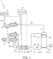
- FIG. 1 is a schematic view for illustrating a configuration of a gas turbine system 1 according to this embodiment.
- the gas turbine system 1 includes a turbocharger 11, a power generator 12, a combustor 13, an ammonia tank 14, a pump 15, an air supply source 16, an ammonia autothermal cracking device 17, and a controller 18.
- the combustor 13, the ammonia tank 14, the pump 15, the air supply source 16, the ammonia autothermal cracking device 17, and the controller 18 of the gas turbine system 1 are included in a combustion device 10.
- a first flow rate control valve 201, a second flow rate control valve 202, and an air flow rate control valve 301, which are described later, are also included in the combustion device 10.
- the turbocharger 11 includes a compressor 11a and a turbine 11b.
- the compressor 11a and the turbine 11b rotate integrally.
- the compressor 11a and the turbine 11b are coupled to each other through intermediation of a shaft.
- the compressor 11a is provided in an intake flow passage 101 connected to the combustor 13. Air to be supplied to the combustor 13 flows through the intake flow passage 101.
- An intake port (not shown) is formed at an upstream-side end portion of the intake flow passage 101. The intake port allows air to be introduced from an outside. The air introduced through the intake port passes through the compressor 11a and is sent to the combustor 13. The compressor 11a compresses the air and discharges the compressed air to a downstream side.
- the turbine 11b is provided in an exhaust flow passage 102 connected to the combustor 13.
- An exhaust gas discharged from the combustor 13 flows through the exhaust flow passage 102.
- An exhaust port (not shown) is formed at a downstream-side end portion of the exhaust flow passage 102. The exhaust port allows the exhaust gas to be discharged to the outside.
- the exhaust gas discharged from the combustor 13 passes through the turbine 11b and is sent to the exhaust port.
- the turbine 11b is rotated by the exhaust gas to generate rotational power.
- the power generator 12 is connected to the turbocharger 11.
- the power generator 12 generates electric power with use of the rotational power generated by the turbocharger 11.
- ammonia is mainly used as fuel to cause combustion.
- a cracked gas supplied from the ammonia autothermal cracking device 17 is also used as fuel.
- the combustor 13 includes a combustion chamber (not shown).
- the air compressed by the compressor 11a is supplied to the combustion chamber of the combustor 13 through the intake flow passage 101.
- Fuel is supplied to the combustion chamber of the combustor 13.
- liquid ammonia is supplied as fuel from the ammonia tank 14 and is sprayed into the combustion chamber of the combustor 13.
- An air-fuel mixture containing fuel and air is generated in the combustion chamber of the combustor 13.
- An exhaust gas generated as a result of combustion in the combustion chamber of the combustor 13 is discharged to the exhaust flow passage 102.
- the liquid ammonia is stored in the ammonia tank 14.
- the ammonia tank 14 is connected to each of the combustor 13 and the ammonia autothermal cracking device 17. In this manner, ammonia can be supplied from the ammonia tank 14 to each of the combustor 13 and the ammonia autothermal cracking device 17.
- a flow passage 103 is connected to the ammonia tank 14.
- a flow passage 104 and a flow passage 105 are connected to a downstream-side end portion of the flow passage 103.
- the flow passage 104 is connected to the combustor 13. That is, the ammonia tank 14 is connected to the combustor 13 through intermediation of the flow passage 103 and the flow passage 104.
- the liquid ammonia is supplied from the ammonia tank 14 to the combustion chamber of the combustor 13 via the flow passage 103 and the flow passage 104.
- the flow passage 105 is connected to the ammonia autothermal cracking device 17. That is, the ammonia tank 14 is connected to the ammonia autothermal cracking device 17 through intermediation of the flow passage 103 and the flow passage 105.
- the liquid ammonia is supplied from the ammonia tank 14 to the ammonia autothermal cracking device 17 via the flow passage 103 and the flow passage 105.
- the pump 15 is provided in the flow passage 103.
- the pump 15 feeds the ammonia supplied from the ammonia tank 14 to a downstream side.
- the ammonia fed by the pump 15 passes through the flow passage 103 and is sent to the flow passage 104 and the flow passage 105.
- the first flow rate control valve 201 is provided in the flow passage 104.
- the first flow rate control valve 201 controls a flow rate of ammonia flowing through the flow passage 104.
- the first flow rate control valve 201 adjusts a supply amount of ammonia from the ammonia tank 14 to the combustor 13.
- the supply amount of ammonia from the ammonia tank 14 to the combustor 13 is adjusted through adjustment of an opening degree of the first flow rate control valve 201.
- the second flow rate control valve 202 is provided in the flow passage 105.
- the second flow rate control valve 202 controls a flow rate of ammonia flowing through the flow passage 105.
- the second flow rate control valve 202 adjusts a supply amount of ammonia from the ammonia tank 14 to the ammonia autothermal cracking device 17.
- the supply amount of ammonia from the ammonia tank 14 to the ammonia autothermal cracking device 17 is adjusted through adjustment of an opening degree of the second flow rate control valve 202.
- the air supply source 16 is a supply source that supplies air.
- the air supply source 16 is, for example, a compressor that compresses and discharges outside air.
- the air supply source 16 is connected to the ammonia autothermal cracking device 17 through intermediation of a flow passage 106. Air is supplied from the air supply source 16 to the ammonia autothermal cracking device 17 via the flow passage 16.
- the air flow rate control valve 301 is provided in the flow passage 106.
- the air flow rate control valve 301 controls a flow rate of air flowing through the flow passage 106.
- the air flow rate control valve 301 adjusts a supply amount of air from the air supply source 16 to the ammonia autothermal cracking device 17.
- the supply amount of air from the air supply source 16 to the ammonia autothermal cracking device 17 is adjusted through adjustment of an opening degree of the air flow rate control valve 301.
- the ammonia autothermal cracking device 17 combusts part of ammonia and cracks the remaining ammonia with heat generated by the combustion.
- the ammonia autothermal cracking device 17 is also called "autothermal reactor".
- the ammonia autothermal cracking device 17 includes a heater 17a and a catalyst 17b.
- the heater 17a heats an inside of the ammonia autothermal cracking device 17.
- the catalyst 17b promotes the combustion and the cracking of ammonia.
- a temperature sensor 401 that detects a temperature of the catalyst 17b is provided in the ammonia autothermal cracking device 17.
- the ammonia tank 14 is connected to an inlet 17c1 of the ammonia autothermal cracking device 17 through intermediation of the flow passage 105.
- the air supply source 16 is connected to an inlet 17c2 of the ammonia autothermal cracking device 17 through intermediation of the flow passage 106.
- the combustor 13 is connected to an outlet 17d of the ammonia autothermal cracking device 17 through intermediation of a flow passage 107.
- Ammonia is supplied into the ammonia autothermal cracking device 17 via the inlet 17c1.
- a nozzle that sprays liquid ammonia is provided at the inlet 17c1.
- Ammonia is sprayed from the nozzle into the ammonia autothermal cracking device 17.
- Air is supplied into the ammonia autothermal cracking device 17 via the inlet 17c2.
- the ammonia and the air that are supplied into the ammonia autothermal cracking device 17 are heated by the heater 17a.
- the ammonia is vaporized.
- part of the ammonia is combusted in the catalyst 17b.
- the remaining ammonia is cracked into hydrogen and nitrogen by heat generated at this time.
- a cracked gas generated as a result of the cracking of ammonia contains hydrogen and nitrogen.
- the cracked gas generated in the ammonia autothermal cracking device 17 is discharged from the outlet 17d of the ammonia autothermal cracking device 17.
- the cracked gas discharged from the outlet 17d is sent to the combustion chamber of the combustor 13 through the flow passage 107.
- the cracked gas may contain not only hydrogen and nitrogen but also, for example, uncracked ammonia.
- the controller 18 includes, for example, a central processing unit (CPU), a ROM that stores, for example, a program, and a RAM serving as a work area.
- the controller 18 controls the whole gas turbine system 1.
- the controller 18 controls the pump 15, the heater 17a, the first flow rate control valve 201, the second flow rate control valve 202, and the air flow rate control valve 301. Further, the controller 18 acquires a detection result from the temperature sensor 401.
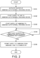
- FIG. 2 is a flowchart for illustrating one example of flow of processing associated with activation of the gas turbine system 1.
- the processing flow illustrated in FIG. 2 is performed by the controller 18.
- the processing flow illustrated in FIG. 2 is executed when an activation condition for the gas turbine system 1 is satisfied.
- the activation condition is that, for example, an input operation for activating the gas turbine system 1 is performed by a user.
- the controller 18 activates the heater 17a of the ammonia autothermal cracking device 17 in Step S101.
- Step S102 the controller 18 starts the supply of air to the ammonia autothermal cracking device 17.
- the controller 18 opens the air flow rate control valve 301 that is in a closed state.
- Step S103 the controller 18 starts the supply of ammonia to the ammonia autothermal cracking device 17.
- the controller 18 drives the pump 15 and opens the second flow rate control valve 202 that is in a closed state.
- the cracked gas is generated in the ammonia autothermal cracking device 17. Then, the generated cracked gas is sent to the combustor 13. Ignition is performed by an ignition device (not shown) in the combustor 13. As described above, at the time of activation of the gas turbine system 1, ignition is performed under a state in which the cracked gas is supplied to the combustor 13. Specifically, the cracked gas is used as fuel for ignition. Unlike ammonia, hydrogen contained in the cracked gas is combustible and thus is more likely to be ignited. Hence, a failure in ignition is suppressed, and reliability of ignition is improved.
- Step S104 the controller 18 determines whether or not an input heat quantity to the combustor 13 has exceeded a reference heat quantity.
- the input heat quantity to the combustor 13 is a heat quantity generated as a result of combustion of fuel input to the combustor 13.
- the controller 18 can estimate the input heat quantity to the combustor 13 based on, for example, a supply amount of fuel to the combustor 13.
- the reference heat quantity is set to a value around which combustibility in the combustor 13 is maintained to a predetermined level or higher even after the supply of ammonia to the combustor 13 is started.
- the predetermined level is a level around which occurrence of non-combustion of part of ammonia is suppressed.
- Step S104 When it is determined that the input heat quantity to the combustor 13 has exceeded the reference heat quantity (YES in Step S104), the controller 18 determines that the combustibility in the combustor 13 is maintained to the predetermined level or higher even after the supply of ammonia to the combustor 13 is started. Then, the processing proceeds to Step S105. Meanwhile, when it is determined that the input heat quantity to the combustor 13 has not exceeded the reference heat quantity (NO in Step S104), the controller 18 determines that the combustibility in the combustor 13 decreases to be below the predetermined level after the supply of ammonia to the combustor 13 is started. Then, the processing in Step S104 is repeated.
- Step S104 the controller 18 permits the supply of ammonia from the ammonia tank 14 to the combustor 13 in Step S105. Then, the processing flow illustrated in FIG. 2 ends.
- Step S105 specifically, when a required output for the gas turbine system 1 is equal to or larger than a reference output, the controller 18 starts the supply of ammonia from the ammonia tank 14 to the combustor 13. In this case, the controller 18 opens the first flow rate control valve 201 that is in a closed state. As a result, combustion using ammonia as fuel is started.
- the required output for the gas turbine system 1 is smaller than the reference output, the supply of ammonia from the ammonia tank 14 to the combustor 13 is not required.
- the combustion using ammonia as fuel is started under a state in which the cracked gas is supplied to the combustor 13 and the combustibility is maintained at the predetermined level or higher. Specifically, the cracked gas is used as fuel for combustion aid. As a result, occurrence of non-combustion of part of ammonia is suppressed.
- the controller 18 may continue or stop the supply of the cracked gas to the combustor 13. When the supply of the cracked gas to the combustor 13 is stopped, the controller 18 stops the heater 17a and stops the supply of air and ammonia to the ammonia autothermal cracking device 17.
- the controller 18 may stop the heater 17a.
- a reaction in which ammonia is cracked corresponds to the endothermic reaction.
- a reaction in which ammonia is combusted corresponds to the exothermic reaction.
- the controller 18 may determine that the state in the ammonia autothermal cracking device 17 has become close to a thermal equilibrium state and may stop the heater 17a.
- the inlets 17c1 and 17c2 of the ammonia autothermal cracking device 17 are connected to the ammonia tank 14 and the air supply source 16, respectively.
- the outlet 17d of the ammonia autothermal cracking device 17 is connected to the combustor 13.
- the cracked gas can be generated by using the ammonia autothermal cracking device 17.
- the gas turbine system 1 can be quickly activated.
- An example of another method includes, for example, as described later with reference to FIG. 3 or FIG. 5 , a method of generating a cracked gas by supplying ammonia to an ammonia cracking catalyst 19 provided in the intake flow passage 101 or the exhaust flow passage 102. If the cracked gas generated by the above-mentioned method is supplied to the combustor 13 at the time of activation of the gas turbine system 1, the ammonia cracking catalyst 19 is required to be heated to a temperature around which the cracking of ammonia actively occurs.
- the ammonia is cracked by using the heat generated as a result of the combustion of part of ammonia in the ammonia autothermal cracking device 17. Hence, time required to start the generation of the cracked gas can be reduced, and thus the gas turbine system 1 can be quickly activated.
- FIG. 3 is a schematic view for illustrating a configuration of a gas turbine system 1A according to a first modification example. As illustrated in FIG. 3 , the gas turbine system 1A according to the first modification example is different from the gas turbine system 1 described above in that an ammonia cracking catalyst 19 is further provided.
- a combustor 13, an ammonia tank 14, a pump 15, an air supply source 16, an ammonia autothermal cracking device 17, a controller 18, the ammonia cracking catalyst 19, a first flow rate control valve 201, a second flow rate control valve 202, and an air flow rate control valve 301 of the gas turbine system 1A are included in a combustion device 10A.
- the ammonia cracking catalyst 19 cracks ammonia and generates a cracked gas.
- the ammonia cracking catalyst 19 cracks ammonia into hydrogen and nitrogen.
- the cracked gas contains hydrogen and nitrogen.
- the cracked gas may contain uncracked ammonia in addition to hydrogen and nitrogen.
- the ammonia cracking catalyst 19 is connected to the ammonia tank 14 through intermediation of a flow passage 103 and a flow passage 108.
- the flow passage 108 is connected to a downstream-side end portion of the flow passage 103. Liquid ammonia is supplied from the ammonia tank 14 to the ammonia cracking catalyst 19 via the flow passage 103 and the flow passage 108.
- the third flow rate control valve 203 is provided in the flow passage 108.
- the third flow rate control valve 203 controls a flow rate of ammonia flowing through the flow passage 108.
- the third flow rate control valve 203 adjusts a supply amount of ammonia from the ammonia tank 14 to the ammonia cracking catalyst 19.
- the supply amount of ammonia from the ammonia tank 14 to the ammonia cracking catalyst 19 is adjusted through adjustment of an opening degree of the third flow rate control valve 203.
- the ammonia cracking catalyst 19 is connected to the combustor 13 through intermediation of a flow passage 109.
- a cracked gas generated from the ammonia cracking catalyst 19 is sent to a combustion chamber of the combustor 13 through the flow passage 109.
- the cracking of ammonia with the ammonia cracking catalyst 19 actively occurs when a temperature of the ammonia cracking catalyst 19 is equal to or higher than a reference temperature (for example, from about 400°C to about 500°C). Specifically, when the temperature of the ammonia cracking catalyst 19 becomes equal to or higher than the reference temperature, the cracking of ammonia can actively occur with the ammonia cracking catalyst 19.
- a reference temperature for example, from about 400°C to about 500°C.
- the ammonia cracking catalyst 19 is provided in an intake flow passage 101. More specifically, the ammonia cracking catalyst 19 is provided on a downstream side of a compressor 11a in the intake flow passage 101.
- the ammonia cracking catalyst 19 and air in the intake flow passage 101 can exchange heat under a state in which an internal space of the ammonia cracking catalyst 19 and the intake flow passage 101 are not in communication with each other. Air flowing on a downstream side of the compressor 11a in the intake flow passage 101 has been compressed by the compressor 11a, and thus has a high temperature (for example, 400°C or higher). Hence, the ammonia cracking catalyst 19 is heated with the air flowing through the intake flow passage 101 to a temperature around which the cracking of ammonia actively occurs during an operation of the gas turbine system 1A.
- a temperature sensor 402 is provided to the ammonia cracking catalyst 19.
- the temperature sensor 402 detects a temperature of the ammonia cracking catalyst 19.
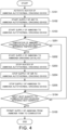
- FIG. 4 is a flowchart for illustrating one example of flow of processing associated with activation of the gas turbine system 1A.
- the processing flow illustrated in FIG. 4 is performed by the controller 18.
- the processing flow illustrated in FIG. 4 is executed when an activation condition for the gas turbine system 1A is satisfied.
- the processing flow illustrated in FIG. 4 is different from the processing flow illustrated in FIG. 2 in that Steps S201, S202, S203, S204, and S205 are added between Step S103 and Step S104.
- Step S201 the controller 18 determines whether or not a temperature of the ammonia cracking catalyst 19 has reached the reference temperature.
- the processing proceeds to Step S202.
- Steps S202, S203, S204, and S205 are skipped and the processing proceeds to Step S104.
- Step S201 the controller 18 starts the supply of ammonia to the ammonia cracking catalyst 19 in Step S202. Specifically, the controller 18 opens the third flow rate control valve 203 that is in a closed state. As a result, when ammonia is cracked with the ammonia cracking catalyst 19, the cracked gas is generated. Then, the thus generated cracked gas is sent to the combustor 13.
- Step S203 the controller 18 stops a heater 17a of the ammonia autothermal cracking device 17.
- Step S204 the controller 18 stops the supply of air to the ammonia autothermal cracking device 17. Specifically, the controller 18 closes the air flow rate control valve 301.
- Step S205 the controller 18 stops the supply of ammonia to the ammonia autothermal cracking device 17. Specifically, the controller 18 closes the second flow rate control valve 202.
- Step S104 the controller 18 determines whether or not an input heat quantity to the combustor 13 has exceeded a reference heat quantity.
- Step S105 the processing flow illustrated in FIG. 2 .
- the processing returns to Step S201.
- the gas turbine system 1A not only the ammonia autothermal cracking device 17 but also the ammonia cracking catalyst 19 is provided.
- a method of generating the cracked gas to be supplied to the combustor 13 can be switched from a method of using the ammonia autothermal cracking device 17 to a method of using the ammonia cracking catalyst 19.
- the cracked gas is generated by using the ammonia autothermal cracking device 17.
- the cracked gas is generated by using the ammonia cracking catalyst 19.
- the cracked gas can be generated by effectively using heat of the air flowing through the intake flow passage 101.
- energy consumed for the supply of air to the ammonia autothermal cracking device 17 and energy consumed for driving of the heater 17a can be reduced.
- FIG. 5 is a schematic view for illustrating a configuration of a gas turbine system 1B according to a second modification example. As illustrated in FIG. 2 , the gas turbine system 1B according to the second modification example is different from the gas turbine system 1A described above in arrangement of an ammonia cracking catalyst 19.
- a combustor 13, an ammonia tank 14, a pump 15, an air supply source 16, an ammonia autothermal cracking device 17, a controller 18, the ammonia cracking catalyst 19, a first flow rate control valve 201, a second flow rate control valve 202, a third flow rate control valve 203, and an air flow rate control valve 301 of the gas turbine system 1B are included in a combustion device 10B.
- the ammonia cracking catalyst 19 is connected to the ammonia tank 14 through intermediation of a flow passage 103 and a flow passage 108.
- the ammonia cracking catalyst 19 is connected to the combustor 13 through intermediation of a flow passage 109.
- the gas turbine system 1B is different from the gas turbine system 1A described above in that the ammonia cracking catalyst 19 is provided in an exhaust flow passage 102. Specifically, the ammonia cracking catalyst 19 is provided on a downstream side of a turbine 11b in the exhaust flow passage 102.
- the ammonia cracking catalyst 19 and an exhaust gas in the exhaust flow passage 102 can exchange heat under a state in which an internal space of the ammonia cracking catalyst 19 and the exhaust flow passage 102 are not in communication with each other.
- the exhaust gas flowing through the exhaust flow passage 102 has a high temperature (for example, 550°C or higher). Hence, the ammonia cracking catalyst 19 is heated with the exhaust gas flowing through the exhaust flow passage 102 to a temperature around which the cracking of ammonia actively occurs during an operation of the gas turbine system 1B.
- the gas turbine system 1B not only the ammonia autothermal cracking device 17 but also the ammonia cracking catalyst 19 is provided.
- a method of generating the cracked gas to be supplied to the combustor 13 can be switched from a method of using the ammonia autothermal cracking device 17 to a method of using the ammonia cracking catalyst 19.
- the cracked gas can be generated by effectively using heat of the exhaust gas flowing through the exhaust flow passage 102.
- energy consumed for the supply of air to the ammonia autothermal cracking device 17 and energy consumed for driving of the heater 17a can be reduced.
- Processing associated with activation of the gas turbine system 1B is similar to the processing associated with the above-mentioned activation of the gas turbine system 1A, and thus description thereof is omitted.
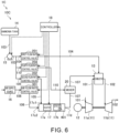
- FIG. 6 is a schematic view for illustrating a configuration of a gas turbine system 1C according to a third modification example. As illustrated in FIG. 6 , the gas turbine system 1C according to the third modification example is different from the gas turbine system 1 described above in that a mixer 20 is further provided.
- a combustor 13, an ammonia tank 14, a pump 15, an air supply source 16, an ammonia autothermal cracking device 17, a controller 18, the mixer 20, a first flow rate control valve 201, a second flow rate control valve 202, and an air flow rate control valve 301 of the gas turbine system 1C are included in a combustion device 10C.
- a fourth flow rate control valve 204, which is described later, is also included in the combustion device 10C.
- the mixer 20 is provided in a flow passage 107 that connects the ammonia autothermal cracking device 17 and the combustor 13 to each other.
- An internal space of the mixer 20 is in communication with the flow passage 107.
- the mixer 20 is connected to the ammonia tank 14 through intermediation of a flow passage 103 and a flow passage 110.
- the flow passage 110 is connected to a downstream-side end portion of the flow passage 103. Liquid ammonia is supplied from the ammonia tank 14 to the mixer 20 via the flow passage 103 and the flow passage 110.
- the fourth flow rate control valve 204 is provided in the flow passage 110.
- the fourth flow rate control valve 204 controls a flow rate of ammonia flowing through the flow passage 110. Specifically, the fourth flow rate control valve 204 adjusts a supply amount of ammonia from the ammonia tank 14 to the mixer 20. The supply amount of ammonia from the ammonia tank 14 to the mixer 20 is adjusted through adjustment of an opening degree of the fourth flow rate control valve 204.
- the ammonia sent from the ammonia tank 14 to the mixer 20 is sprayed into the mixer 20. Then, a cracked gas flowing through the flow passage 107 and the ammonia sprayed into the mixer 20 are mixed in the mixer 20.
- the cracked gas flowing through the flow passage 107 has a high temperature (for example, about 500°C). Hence, the ammonia sprayed into the mixer 20 is vaporized. The vaporized ammonia is sent together with the cracked gas to the combustor 13 through the flow passage 107.
- FIG. 7 is a flowchart for illustrating one example of flow of processing associated with activation of the gas turbine system 1C.
- the processing flow illustrated in FIG. 7 is performed by the controller 18.
- the processing flow illustrated in FIG. 7 is executed when an activation condition for the gas turbine system 1C is satisfied.
- the processing flow illustrated in FIG. 7 is different from the processing flow illustrated in FIG. 2 in that Steps S301 and S302 are added between Step S104 and Step S105.
- Step S301 the controller 18 permits the supply of ammonia from the ammonia tank 14 to the mixer 20.
- Step S301 when a required output for the gas turbine system 1 is equal to or larger than a reference output, the controller 18 starts the supply of ammonia from the ammonia tank 14 to the mixer 20.
- the controller 18 opens the fourth flow rate control valve 204 that is in a closed state.
- ammonia is sent together with the cracked gas from the mixer 20 to the combustor 13.
- combustion using ammonia as fuel is started.
- the required output for the gas turbine system 1 is smaller than the reference output, the supply of ammonia from the ammonia tank 14 to the mixer 20 is not required.
- the ammonia sent from the mixer 20 to the combustor 13 is heated with the cracked gas and is vaporized.
- evaporation of ammonia in the combustor 13, which may occur when liquid ammonia is directly supplied to the combustor 13, is suppressed, and thus a decrease in temperature, which may locally occur due to the evaporation of ammonia, is suppressed. Accordingly, discharge of non-combusted ammonia and nitrous oxide (N 2 O) is suppressed.
- Step S302 the controller 18 determines whether or not the input heat quantity to the combustor 13 has exceeded a heat-quantity threshold value.
- the heat-quantity threshold value is an index for determining that the input heat quantity is large enough to suppress the discharge of non-combusted ammonia and nitrous oxide (N 2 O) even after the supply of liquid ammonia to the combustor 13 is started.
- Step S302 When it is determined that the input heat quantity to the combustor 13 has exceeded the heat-quantity threshold value (YES in Step S302), the controller 18 determines that the input heat quantity is large enough to suppress the discharge of non-combusted ammonia and nitrous oxide (N 2 O) even after the supply of liquid ammonia to the combustor 13 is started. Then, the processing proceeds to Step S105. In Step S105, the controller 18 permits the supply of liquid ammonia from the ammonia tank 14 to the combustor 13. Then, the processing flow illustrated in FIG. 7 ends.
- Step S302 when it is determined that the input heat quantity to the combustor 13 has not exceeded the heat-quantity threshold value (NO in Step S302), the controller 18 determines that a certain amount of non-combusted ammonia and nitrous oxide (N 2 O) is generated after the supply of liquid ammonia to the combustor 13 is started. Then, Step S302 is repeated.
- the mixer 20 is provided in the flow passage 107 that connects the ammonia autothermal cracking device 17 and the combustor 13 to each other, and the mixer 20 is connected to the ammonia tank 14.
- liquid ammonia can be heated with the cracked gas and be vaporized in the mixer 20.
- the vaporized ammonia can be sent from the mixer 20 to the combustor 13 before the input heat quantity to the combustor 13 reaches the heat-quantity threshold value.
- the evaporation of ammonia in the combustor 13 is suppressed, and the discharge of non-combusted ammonia and nitrous oxide (N 2 O) is suppressed.
- FIG. 8 is a schematic view for illustrating a configuration of a gas turbine system 1D according to a fourth modification example. As illustrated in FIG. 8 , the gas turbine system 1D according to the fourth modification example is different from the gas turbine system 1 described above in that a first heat exchanger 21 is further provided.
- a combustor 13, an ammonia tank 14, a pump 15, an air supply source 16, an ammonia autothermal cracking device 17, a controller 18, the first heat exchanger 21, a first flow rate control valve 201, a second flow rate control valve 202, and an air flow rate control valve 301 of the gas turbine system 1D are included in a combustion device 10D.
- a fifth flow rate control valve 205, which is described later, is also included in the combustion device 10D.
- a flow passage 111 is provided in addition to a flow passage 105 as flow passages that connect the ammonia tank 14 and the ammonia autothermal cracking device 17 to each other.
- the flow passage 111 is connected to a downstream-side end portion of a flow passage 103.
- the flow passage 111 is connected to an inlet 17c3 of the ammonia autothermal cracking device 17.
- ammonia can be supplied from the ammonia tank 14 to the inlet 17c3 of the ammonia autothermal cracking device 17 via the flow passage 103 and the flow passage 111.
- the flow passage 111 is also referred to as "first flow passage 111".
- the flow passage 105 is also referred to as "second flow passage 105".
- the fifth flow rate control valve 205 is provided in the first flow passage 111.
- the fifth flow rate control valve 205 controls a flow rate of ammonia flowing through the flow passage 111.
- the fifth flow rate control valve 205 adjusts a supply amount of ammonia which is to be supplied from the ammonia tank 14 through the first flow passage 111 to the ammonia autothermal cracking device 17.
- an opening degree of the fifth flow rate control valve 205 is adjusted, the supply amount of ammonia to be supplied from the ammonia tank 14 through the first flow passage 111 to the ammonia autothermal cracking device 17 is adjusted.
- the first flow passage 111 passes through the first heat exchanger 21. Specifically, part of the first flow passage 111, which is located on a downstream side of the fifth flow rate control valve 205, passes through the first heat exchanger 21.
- the first heat exchanger 21 is provided in a flow passage 107 that connects the ammonia autothermal cracking device 17 and the combustor 13 to each other. That is, ammonia in the first flow passage 111 and a cracked gas in the flow passage 107 can exchange heat. Liquid ammonia flowing through the first flow passage 111 is heated with the cracked gas and is vaporized in the first heat exchanger 21.
- the vaporized ammonia is sent to the inlet 17c3 of the ammonia autothermal cracking device 17 through the first flow passage 111.
- a nozzle that sprays gaseous ammonia is provided at the inlet 17c3. Ammonia is sprayed from the nozzle into the ammonia autothermal cracking device 17.
- the second flow passage 105 bypasses the first heat exchanger 21. Specifically, the second flow passage 105 does not pass through the first heat exchanger 21. Hence, the liquid ammonia is sent to the inlet 17c1 of the ammonia autothermal cracking device 17 through the second flow passage 105. As described above, a nozzle that sprays liquid ammonia is provided at the inlet 17c1. Ammonia is sprayed from the nozzle into the ammonia autothermal cracking device 17.
- a temperature sensor 403 is provided on a downstream side of the first heat exchanger 21 in the flow passage 107.
- the temperature sensor 403 detects a temperature of the cracked gas on the downstream side of the first heat exchanger 21 in the flow passage 107.
- the temperature sensor 403 is arranged, for example, in the vicinity of the first heat exchanger 21.
- FIG. 9 is a flowchart for illustrating one example of flow of processing associated with activation of the gas turbine system 1D.
- the processing flow illustrated in FIG. 9 is performed by the controller 18.
- the processing flow illustrated in FIG. 9 is executed when an activation condition for the gas turbine system 1D is satisfied.
- Step S103 is omitted and Steps S401, S402, and S403 are added between Step S102 and Step S104.
- Step S401 subsequent to Step S102 the controller 18 starts the supply of ammonia to the ammonia autothermal cracking device 17 by using the second flow passage 105.
- the controller 18 drives the pump 15 and opens the second flow rate control valve 202 that is in a closed state.
- liquid ammonia is sent to the ammonia autothermal cracking device 17 through the second flow passage 105 and is supplied from the inlet 17c1 of the ammonia autothermal cracking device 17 into the ammonia autothermal cracking device 17.
- a cracked gas is generated in the ammonia autothermal cracking device 17.
- the thus generated cracked gas is sent to the combustor 13.
- Step S402 the controller 18 determines whether or not a temperature of the cracked gas passing through the first heat exchanger 21 has exceeded a temperature threshold value.
- the temperature threshold value is an index for determining that the temperature of the cracked gas is high enough to vaporize ammonia in the first heat exchanger 21.
- a result of detection performed by the temperature sensor 403 is used as the temperature of the cracked gas passing through the first heat exchanger 21.
- Step S402 When it is determined that the temperature of the cracked gas passing through the first heat exchanger 21 has exceeded the temperature threshold value (YES in Step S402), the controller 18 determines that the temperature of the cracked gas is high enough to vaporize ammonia in the first heat exchanger 21. Then, the processing proceeds to Step S403. Meanwhile, when it is determined that the temperature of the cracked gas passing through the first heat exchanger 21 has not exceeded the temperature threshold value (NO in Step S402), Step S403 is skipped and the processing proceeds to Step S104.
- Step S403 the controller 18 switches a supply passage for ammonia toward the ammonia autothermal cracking device 17 to the first flow passage 111. Specifically, the controller 18 closes the second flow rate control valve 202 and opens the fifth flow rate control valve 205 that is in a closed state. Thus, liquid ammonia is sent from the ammonia tank 14 to the first flow passage 111, and is heated with the cracked gas and vaporized in the first heat exchanger 21. Then, the vaporized ammonia is sent to the ammonia autothermal cracking device 17 through the first flow passage 111 and is supplied from the inlet 17c3 into the ammonia autothermal cracking device 17.
- Step S104 the controller 18 determines whether or not an input heat quantity to the combustor 13 has exceeded a reference heat quantity.
- Step S105 the processing flow illustrated in FIG. 2 .
- the processing returns to Step S402.
- the first heat exchanger 21 is provided in the flow passage 107 that connects the ammonia autothermal cracking device 17 and the combustor 13 to each other, and the first flow passage 111 passes through the first heat exchanger 21.
- liquid ammonia can be heated with the cracked gas and be vaporized in the first heat exchanger 21.
- the vaporized ammonia can be supplied to the ammonia autothermal cracking device 17 via the first flow passage 111.
- ammonia can be combusted and cracked in the ammonia autothermal cracking device 17 without being vaporized. Accordingly, energy efficiency is improved because heat of vaporization for ammonia is not required in the reactions occurring in the ammonia autothermal cracking device 17.
- the second flow passage 105 may be omitted from the configuration of the gas turbine system 1D. In this case, however, there arise two conditions in which liquid ammonia passes through the inlet 17c3 of the ammonia autothermal cracking device 17 and in which gaseous ammonia passes therethrough. Thus, regardless of whether a nozzle for spraying liquid is provided at the inlet 17c3 or a nozzle for spraying gas is provided at the inlet 17c3, a pressure loss in the first flow passage 111 increases. Meanwhile, the second flow passage 105 that bypasses the first heat exchanger 21 is further provided in the gas turbine system 1D.
- ammonia autothermal cracking device 17 when liquid ammonia is supplied to the ammonia autothermal cracking device 17, ammonia is supplied from the nozzle for spaying liquid provided at the inlet 17c1 into the ammonia autothermal cracking device 17.
- gaseous ammonia is supplied to the ammonia autothermal cracking device 17
- ammonia is supplied from the nozzle for spaying gas provided at the inlet 17c3 into the ammonia autothermal cracking device 17.
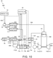
- FIG. 10 is a schematic view for illustrating a configuration of a gas turbine system 1E according to a fifth modification example. As illustrated in FIG. 10 , the gas turbine system 1E according to the fifth modification example is different from the gas turbine system 1D described above in that the second flow passage 105 is omitted and a first flow passage 111 has branches.
- a combustor 13, an ammonia tank 14, a pump 15, an air supply source 16, an ammonia autothermal cracking device 17, a controller 18, a first heat exchanger 21, a first flow rate control valve 201, a fifth flow rate control valve 205, and an air flow rate control valve 301 of the gas turbine system 1E are included in a combustion device 10E.
- the first flow passage 111 branches into a first branch passage 111a and a second branch passage 111b on a side closer to an ammonia autothermal cracking device 17 with respect to the first heat exchanger 21.
- the first branch passage 111a is connected to an inlet 17c1 of the ammonia autothermal cracking device 17.
- the second branch passage 111b is connected to an inlet 17c3 of the ammonia autothermal cracking device 17.
- Ammonia sent from the ammonia tank 14 to the first flow passage 111 is sent to the ammonia autothermal cracking device 17 through the first branch passage 111a or the second branch passage 111b.
- the switching valve 22 that switches a supply passage for ammonia between the first branch passage 111a and the second branch passage 111b is provided in the first flow passage 111.
- the switching valve 22 is provided at a branch portion between the first branch passage 111a and the second branch passage 111b.
- the switching valve 22 is controlled by the controller 18.
- a pressure sensor 404 is provided on an upstream side of the switching valve 22 in the first flow passage 111.
- the pressure sensor 404 detects a pressure on the upstream side of the switching valve 22 in the first flow passage 111.
- a pressure sensor 405 is provided in the ammonia autothermal cracking device 17. The pressure sensor 405 detects a pressure in the ammonia autothermal cracking device 17.
- FIG. 11 is a flowchart for illustrating one example of flow of processing associated with activation of the gas turbine system 1E.
- the processing flow illustrated in FIG. 11 is performed by the controller 18.
- the processing flow illustrated in FIG. 11 is executed when an activation condition for the gas turbine system 1E is satisfied.
- Step S103 is omitted and Steps S501, S502, and S503 are added between Step S102 and Step S104.
- Step S501 subsequent to Step S102 the controller 18 starts the supply of ammonia to the ammonia autothermal cracking device 17 by using the first branch passage 111a.
- the controller 18 controls the switching valve 22 so that ammonia sent to the first flow passage 111 passes through the first branch passage 111a.
- the controller 18 drives the pump 15 and opens the fifth flow rate control valve 205 that is in a closed state.
- liquid ammonia is sent to the first flow passage 111.
- ammonia is not cracked in the ammonia autothermal cracking device 17, and thus ammonia passing through the first flow passage 111 is not heated in the first heat exchanger 21.
- ammonia passing through the first flow passage 111 is not heated in the first heat exchanger 21 to such a degree that ammonia is vaporized.
- liquid ammonia is sent to the ammonia autothermal cracking device 17 through the first branch passage 111a and is supplied from the inlet 17c1 of the ammonia autothermal cracking device 17 into the ammonia autothermal cracking device 17.
- a cracked gas is generated in the ammonia autothermal cracking device 17.
- the thus generated cracked gas is sent to the combustor 13.
- Step S502 the controller 18 determines whether or not a pressure loss in the first flow passage 111 has exceeded a reference value.
- the controller 18 can estimate the pressure loss in the first flow passage 111 based on, for example, a difference between a pressure on an upstream side of the switching valve 22 in the first flow passage 111 and a pressure in the ammonia autothermal cracking device 17.
- a pressure in the combustor 13 may be used in place of the pressure in the ammonia autothermal cracking device 17.
- the reference value is an index for determining that a temperature of the cracked gas is high enough to vaporize ammonia in the first heat exchanger 21.
- a nozzle for spraying liquid is provided at the inlet 17c1 connected to the first branch passage 111a.
- the pressure loss in the first flow passage 111 increases.
- the controller 18 can determine that the temperature of the cracked gas is high enough to vaporize ammonia in the first heat exchanger 21.
- Step S502 When it is determined that the pressure loss in the first flow passage 111 has exceeded the reference value (YES in Step S502), the controller 18 determines that the temperature of the cracked gas is high enough to vaporize ammonia in the first heat exchanger 21. Then, the processing proceeds to Step S503. Meanwhile, when it is determined that the pressure loss in the first flow passage 111 has not exceeded the reference value (NO in Step S502), Step S503 is skipped and the processing proceeds to Step S104.
- Step S503 the controller 18 switches a supply passage for ammonia toward the ammonia autothermal cracking device 17 to the second branch passage 111b. Specifically, the controller 18 controls the switching valve 22 so that ammonia sent to the first flow passage 111 passes through the second branch passage 111b. At this time, the ammonia passing through the first flow passage 111 is heated with the cracked gas and is vaporized in the first heat exchanger 21. Then, the vaporized ammonia is sent to the ammonia autothermal cracking device 17 through the second branch passage 111b and is supplied from the inlet 17c3 into the ammonia autothermal cracking device 17.
- Step S104 the controller 18 determines whether or not an input heat quantity to the combustor 13 has exceeded a reference heat quantity.
- Step S105 the processing flow illustrated in FIG. 2 .
- the processing returns to Step S502.
- the first heat exchanger 21 is provided in the flow passage 107 that connects the ammonia autothermal cracking device 17 and the combustor 13 to each other, and the first flow passage 111 passes through the first heat exchanger 21.
- energy efficiency can be improved because heat of vaporization for ammonia is not required in the reactions occurring in the ammonia autothermal cracking device 17.
- the first flow passage 111 branches into the first branch passage 111a and the second branch passage 111b.
- the first branch passage 111a and the second branch passage 111b are connected to the inlets 17c1 and 17c3 of the ammonia autothermal cracking device 17, respectively.
- ammonia is supplied from the nozzle for spaying liquid provided at the inlet 17c1 into the ammonia autothermal cracking device 17.
- gaseous ammonia is supplied to the ammonia autothermal cracking device 17
- ammonia is supplied from the nozzle for spaying gas provided at the inlet 17c3 into the ammonia autothermal cracking device 17.
- the supply passage for ammonia through the first flow passage 111 may be switched by a mechanism other than the switching valve 22.
- an on-off valve capable of opening and closing a flow passage may be provided to each of the first branch passage 111a and the second branch passage 111b.
- the on-off valve for the first branch passage 111a is opened and the on-off valve for the second branch passage 111b is closed
- the supply passage for ammonia through the first flow passage 111 is switched to the first branch passage 111a.
- the on-off valve for the first branch passage 111a is closed and the on-off valve for the second branch passage 111b is opened, the supply passage for ammonia through the first flow passage 111 is switched to the second branch passage 111b.
- FIG. 12 is a schematic view for illustrating a configuration of a gas turbine system 1F according to a sixth modification example. As illustrated in FIG. 12 , the gas turbine system 1F according to the sixth modification example is different from the gas turbine system 1 described above in a connection relationship among an ammonia tank 14, an air supply source 16, and an ammonia autothermal cracking device 17.
- a combustor 13, an ammonia tank 14, a pump 15, an air supply source 16, an ammonia autothermal cracking device 17, a controller 18, a first flow rate control valve 201, and an air flow rate control valve 301 of the gas turbine system 1F are included in a combustion device 10F.
- the ammonia tank 14 is connected to an inlet 17c2 of the ammonia autothermal cracking device 17 through intermediation of the air supply source 16.
- the ammonia tank 14 is connected to the air supply source 16 through intermediation of a flow passage 103 and a flow passage 112.
- the flow passage 112 is connected to a downstream-side end portion of the flow passage 103.
- Liquid ammonia is supplied from the ammonia tank 14 to the air supply source 16 via the flow passage 103 and the flow passage 112.
- the ammonia supplied to the air supply source 16 is sent together with air to the ammonia autothermal cracking device 17 through a flow passage 106.
- the ammonia tank 14 is connected to the inlet 17c2 of the ammonia autothermal cracking device 17 through intermediation of the air supply source 16.
- the air supply source 16 is cooled with ammonia supplied from the ammonia tank 14.
- a plurality of compressors arranged in multiple stages are used as the air supply source 16 in some cases. In such cases, air flows in order through the plurality of compressors arranged in series.
- the multi-stage arrangement of the plurality of compressors can reduce compression power in each of the compressors.
- the compressor in an intermediate stage is cooled with the ammonia supplied from the ammonia tank 14.
- the ammonia sent to the ammonia autothermal cracking device 17 is heated by the air supply source 16, and thus a heater 17a is not required in some cases.
- Processing associated with activation of the gas turbine system 1F is substantially similar to the processing associated with the above-mentioned activation of the gas turbine system 1, and thus description thereof is omitted.
- the activation of the gas turbine system 1F is different from the activation of the gas turbine system 1 described above in that the supply of ammonia to the ammonia autothermal cracking device 17 is achieved by the air flow rate control valve 301.
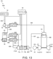
- FIG. 13 is a schematic view for illustrating a configuration of a gas turbine system 1G according to a seventh modification example. As illustrated in FIG. 13 , the gas turbine system 1G according to the seventh modification example is different from the gas turbine system 1 described above in that a second heat exchanger 23 is further provided.
- a combustor 13, an ammonia tank 14, a pump 15, an air supply source 16, an ammonia autothermal cracking device 17, a controller 18, the second heat exchanger 23, a first flow rate control valve 201, a second flow rate control valve 202, and an air flow rate control valve 301 of the gas turbine system 1G are included in a combustion device 10F.
- the second heat exchanger 23 is provided in the air supply source 16.
- a flow passage 105 that connects the ammonia tank 14 and the ammonia autothermal cracking device 17 to each other passes through the second heat exchanger 23.
- Ammonia in the flow passage 105 and the air supply source 16 can exchange heat under a state in which the flow passage 105 and an internal space of the air supply source 16 are not in communication with each other.
- the air supply source 16 is cooled with the ammonia flowing through the flow passage 105 in the second heat exchanger 23.
- the compressor in an intermediate stage is cooled in the second heat exchanger 23.
- the ammonia sent to the ammonia autothermal cracking device 17 is heated by the air supply source 16, and thus a heater 17a is not required in some cases.
- Processing associated with activation of the gas turbine system 1G is similar to the processing associated with the above-mentioned activation of the gas turbine system 1, and thus description thereof is omitted.
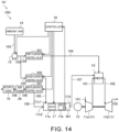
- FIG. 14 is a schematic view for illustrating a configuration of a gas turbine system 1H according to an eighth modification example. As illustrated in FIG. 14 , the gas turbine system 1H according to the eighth modification example is different from the gas turbine system 1 described above in that an air tank 24 is further provided.
- a combustor 13, an ammonia tank 14, a pump 15, an air supply source 16, an ammonia autothermal cracking device 17, a controller 18, the air tank 24, a first flow rate control valve 201, a second flow rate control valve 202, and an air flow rate control valve 301 of the gas turbine system 1H are included in a combustion device 10H.
- the air tank 24 stores air.
- the air tank 24 is provided on a downstream side of the air supply source 16 and an upstream side of the air flow rate control valve 301 in a flow passage 106.
- the air supply source 16 is connected to an inlet 17c2 of the ammonia autothermal cracking device 17 through intermediation of the air tank 24.
- Processing associated with activation of the gas turbine system 1H is similar to the processing associated with the above-mentioned activation of the gas turbine system 1, and thus description thereof is omitted.
- the rotational power generated by the turbocharger 11 is used as energy for driving the power generator 12 in the gas turbine systems 1, 1A, 1B, 1C, 1D, 1E, 1F, 1G, and 1H.
- the rotational power generated by the turbocharger 11 in the gas turbine systems 1, 1A, 1B, 1C, 1D, 1E, 1F, 1G, and 1H may be used for other purposes of use (for example, for the purpose of driving a mobile body such as a vessel).
- combustion devices 10, 10A, 10B, 10C, 10D, 10E, 10F, 10G, and 10H are used for a gas turbine system.
- the combustion devices 10, 10A, 10B, 10C, 10D, 10E, 10F, 10G, and 10H may be used for a device other than the gas turbine system (for example, an industrial furnace that uses energy recovered from exhaust heat or the like for combustion in a combustor).
- liquid ammonia is supplied to the combustor 13 and the ammonia autothermal cracking device 17 in the gas turbine systems 1, 1A, 1B, 1C, 1F, 1G, and 1H.
- gaseous ammonia may be supplied to the combustor 13 and the ammonia autothermal cracking device 17 in the gas turbine systems 1, 1A, 1B, 1C, 1F, 1G, and 1H.
- a vaporizer may be provided on a downstream side of the pump 15 so that ammonia is supplied to the combustor 13 or the ammonia autothermal cracking device 17 after being vaporized by the vaporizer.
- an accumulator may be provided on a downstream side of the vaporizer.
- the vaporizer and the accumulator may be provided in the flow passage 103 or in each of the flow passages connected to the downstream-side end portion of the flow passage 103.
- the gas turbine systems 1A and 1B each corresponding to the gas turbine system 1 in which the ammonia cracking catalyst 19 is additionally provided in the intake flow passage 101 or the exhaust flow passage 102.
- the ammonia cracking catalyst 19 may be additionally provided in the intake flow passage 101 or the exhaust flow passage 102 in the gas turbine systems 1C, 1D, 1E, 1F, 1G, and 1H.
- the gas turbine system 1C corresponding to the gas turbine system 1 in which the mixer 20 connected to the ammonia tank 14 is additionally provided.
- the mixer 20 connected to the ammonia tank 14 may be additionally provided in the gas turbine systems 1A, 1B, 1D, 1E, 1F, 1G, and 1H.
- the first heat exchanger 21 may be additionally provided and at least the first flow passage 111 may be provided as a flow passage that connects the ammonia tank 14 and the ammonia autothermal cracking device 17 to each other in the gas turbine systems 1A, 1B, 1C, 1F, 1G, and 1H.
- the gas turbine system 1F corresponding to the gas turbine system 1 in which the ammonia tank 14 is connected to the inlet 17c2 of the ammonia autothermal cracking device 17 through intermediation of the air supply source 16.
- the ammonia tank 14 may be connected to the inlet 17c2 of the ammonia autothermal cracking device 17 through intermediation of the air supply source 16 in the gas turbine systems 1A, 1B, 1C, 1D, 1E, and 1H.
- the gas turbine system 1G corresponding to the gas turbine system 1 in which the second heat exchanger 23 is additionally provided and the flow passage that connects the ammonia tank 14 and the ammonia autothermal cracking device 17 to each other passes through the second heat exchanger 23.
- the second heat exchanger 23 may be additionally provided and the flow passage that connects the ammonia tank 14 and the ammonia autothermal cracking device 17 to each other may pass through the second heat exchanger 23 in the gas turbine systems 1A, 1B, 1C, 1D, 1E, and 1H.
- the gas turbine system 1H corresponding to the gas turbine system 1 in which the air tank 24 is additionally provided.
- the air tank 24 may be additionally provided in the gas turbine systems 1A, 1B, 1C, 1D, 1E, 1F, and 1G.
Landscapes
- Engineering & Computer Science (AREA)
- Chemical & Material Sciences (AREA)
- Combustion & Propulsion (AREA)
- Mechanical Engineering (AREA)
- General Engineering & Computer Science (AREA)
- Chemical Kinetics & Catalysis (AREA)
- Incineration Of Waste (AREA)
- Engine Equipment That Uses Special Cycles (AREA)
Abstract
Description
- The present disclosure relates to a combustion device and a gas turbine system. This application claims the benefit of priority to
Japanese Patent Application No. 2021-068650 filed on April 14, 2021 - A gas turbine system that combusts fuel in a combustor to obtain power has been used. As the gas turbine system, for example, there exists a gas turbine system that uses ammonia as fuel, as disclosed in
Patent Literature 1. Emission of carbon dioxide is suppressed by using ammonia as fuel. - Patent Literature 1:
JP 2016-191507 A - Ammonia is less combustible than other fuels and has flame retardancy. Thus, in the combustor in which ammonia is used as fuel, ignition fails in some cases. Further, even when ignition is successfully performed, part of the fuel may be discharged without being combusted.
- An object of the present disclosure is to provide a combustion device and a gas turbine system which are capable of improving combustibility in a combustor in which ammonia is used as fuel.
- In order to solve the above-mentioned problem, according to the present disclosure, there is provided a combustion device including: an ammonia tank; a combustor connected to the ammonia tank; an air supply source; and an ammonia autothermal cracking device having inlets connected to the ammonia tank and the air supply source and an outlet connected to the combustor.
- The combustion device may further include: an intake flow passage and an exhaust flow passage, each being connected to the combustor; and an ammonia cracking catalyst, which is provided in the intake flow passage or the exhaust flow passage and is connected to the ammonia tank and the combustor.
- A mixer may be provided in a flow passage that connects the ammonia autothermal cracking device and the combustor, and the mixer may be connected to the ammonia tank.
- A first heat exchanger may be provided in a flow passage that connects the ammonia autothermal cracking device and the combustor to each other, and a flow passage that connects the ammonia tank and the ammonia autothermal cracking device to each other may include a first flow passage that passes through the first heat exchanger.
- The flow passage that connects the ammonia tank and the ammonia autothermal cracking device to each other may further include a second flow passage that bypasses the first heat exchanger.
- The first flow passage may branch into a first branch passage and a second branch passage on a side closer to the ammonia autothermal cracking device with respect to the first heat exchanger, and the first flow passage and the second branch passage may be connected to the inlets of the ammonia autothermal cracking device, respectively.
- The ammonia tank may be connected to the inlet of the ammonia autothermal cracking device through intermediation of the air supply source.
- A second heat exchanger may be provided in the air supply source, and a flow passage that connects the ammonia tank and the ammonia autothermal cracking device to each other may pass through the second heat exchanger.
- The air supply source may be connected to the inlet of the ammonia autothermal cracking device through intermediation of an air tank.
- In order to solve the above-mentioned problem, according to the present disclosure, there is provided a gas turbine system including the above-mentioned combustion device.
- According to the present disclosure, it is possible to improve combustibility in the combustor in which ammonia is used as fuel.
-
-
FIG. 1 is a schematic view for illustrating a configuration of a gas turbine system according to an embodiment of the present disclosure. -
FIG. 2 is a flowchart for illustrating one example of flow of processing associated with activation of the gas turbine system according to the embodiment of the present disclosure. -
FIG. 3 is a schematic view for illustrating a configuration of a gas turbine system according to a first modification example. -
FIG. 4 is a flowchart for illustrating one example of flow of processing associated with activation of the gas turbine system according to the first modification example. -
FIG. 5 is a schematic view for illustrating a configuration of a gas turbine system according to a second modification example. -
FIG. 6 is a schematic view for illustrating a configuration of a gas turbine system according to a third modification example. -
FIG. 7 is a flowchart for illustrating one example of flow of processing associated with activation of the gas turbine system according to the third modification example. -
FIG. 8 is a schematic view for illustrating a configuration of a gas turbine system according to a fourth modification example. -
FIG. 9 is a flowchart for illustrating one example of flow of processing associated with activation of the gas turbine system according to the fourth modification example. -
FIG. 10 is a schematic view for illustrating a configuration of a gas turbine system according to a fifth modification example. -
FIG. 11 is a flowchart for illustrating one example of flow of processing associated with activation of the gas turbine system according to the fifth modification example. -
FIG. 12 is a schematic view for illustrating a configuration of a gas turbine system according to a sixth modification example. -
FIG. 13 is a schematic view for illustrating a configuration of a gas turbine system according to a seventh modification example. -
FIG. 14 is a schematic view for illustrating a configuration of a gas turbine system according to an eighth modification example. - Now, with reference to the attached drawings, an embodiment of the present disclosure is described. The dimensions, materials, and other specific numerical values represented in the embodiment are merely examples used for facilitating the understanding of the disclosure, and do not limit the present disclosure otherwise particularly noted. Elements having substantially the same functions and configurations herein and in the drawings are denoted by the same reference symbols to omit redundant description thereof. Further, illustration of elements with no direct relationship to the present disclosure is omitted.
-
FIG. 1 is a schematic view for illustrating a configuration of agas turbine system 1 according to this embodiment. As illustrated inFIG. 1 , thegas turbine system 1 includes aturbocharger 11, apower generator 12, acombustor 13, anammonia tank 14, apump 15, anair supply source 16, an ammoniaautothermal cracking device 17, and acontroller 18. - The
combustor 13, theammonia tank 14, thepump 15, theair supply source 16, the ammoniaautothermal cracking device 17, and thecontroller 18 of thegas turbine system 1 are included in acombustion device 10. A first flowrate control valve 201, a second flowrate control valve 202, and an air flowrate control valve 301, which are described later, are also included in thecombustion device 10. - The
turbocharger 11 includes acompressor 11a and aturbine 11b. Thecompressor 11a and theturbine 11b rotate integrally. Thecompressor 11a and theturbine 11b are coupled to each other through intermediation of a shaft. - The
compressor 11a is provided in anintake flow passage 101 connected to thecombustor 13. Air to be supplied to thecombustor 13 flows through theintake flow passage 101. An intake port (not shown) is formed at an upstream-side end portion of theintake flow passage 101. The intake port allows air to be introduced from an outside. The air introduced through the intake port passes through thecompressor 11a and is sent to thecombustor 13. Thecompressor 11a compresses the air and discharges the compressed air to a downstream side. - The
turbine 11b is provided in anexhaust flow passage 102 connected to thecombustor 13. An exhaust gas discharged from thecombustor 13 flows through theexhaust flow passage 102. An exhaust port (not shown) is formed at a downstream-side end portion of theexhaust flow passage 102. The exhaust port allows the exhaust gas to be discharged to the outside. The exhaust gas discharged from thecombustor 13 passes through theturbine 11b and is sent to the exhaust port. Theturbine 11b is rotated by the exhaust gas to generate rotational power. - The
power generator 12 is connected to theturbocharger 11. Thepower generator 12 generates electric power with use of the rotational power generated by theturbocharger 11. - In the
combustor 13, ammonia is mainly used as fuel to cause combustion. As described later, for example, at the time of activation of thegas turbine system 1, a cracked gas supplied from the ammoniaautothermal cracking device 17 is also used as fuel. - The
combustor 13 includes a combustion chamber (not shown). The air compressed by thecompressor 11a is supplied to the combustion chamber of thecombustor 13 through theintake flow passage 101. Fuel is supplied to the combustion chamber of thecombustor 13. For example, liquid ammonia is supplied as fuel from theammonia tank 14 and is sprayed into the combustion chamber of thecombustor 13. An air-fuel mixture containing fuel and air is generated in the combustion chamber of thecombustor 13. An exhaust gas generated as a result of combustion in the combustion chamber of thecombustor 13 is discharged to theexhaust flow passage 102. - The liquid ammonia is stored in the
ammonia tank 14. Theammonia tank 14 is connected to each of thecombustor 13 and the ammoniaautothermal cracking device 17. In this manner, ammonia can be supplied from theammonia tank 14 to each of thecombustor 13 and the ammoniaautothermal cracking device 17. - A
flow passage 103 is connected to theammonia tank 14. Aflow passage 104 and aflow passage 105 are connected to a downstream-side end portion of theflow passage 103. Theflow passage 104 is connected to thecombustor 13. That is, theammonia tank 14 is connected to thecombustor 13 through intermediation of theflow passage 103 and theflow passage 104. The liquid ammonia is supplied from theammonia tank 14 to the combustion chamber of thecombustor 13 via theflow passage 103 and theflow passage 104. Theflow passage 105 is connected to the ammoniaautothermal cracking device 17. That is, theammonia tank 14 is connected to the ammoniaautothermal cracking device 17 through intermediation of theflow passage 103 and theflow passage 105. The liquid ammonia is supplied from theammonia tank 14 to the ammoniaautothermal cracking device 17 via theflow passage 103 and theflow passage 105. - The
pump 15 is provided in theflow passage 103. Thepump 15 feeds the ammonia supplied from theammonia tank 14 to a downstream side. The ammonia fed by thepump 15 passes through theflow passage 103 and is sent to theflow passage 104 and theflow passage 105. - The first flow
rate control valve 201 is provided in theflow passage 104. The first flowrate control valve 201 controls a flow rate of ammonia flowing through theflow passage 104. Specifically, the first flowrate control valve 201 adjusts a supply amount of ammonia from theammonia tank 14 to thecombustor 13. The supply amount of ammonia from theammonia tank 14 to thecombustor 13 is adjusted through adjustment of an opening degree of the first flowrate control valve 201. - The second flow
rate control valve 202 is provided in theflow passage 105. The second flowrate control valve 202 controls a flow rate of ammonia flowing through theflow passage 105. Specifically, the second flowrate control valve 202 adjusts a supply amount of ammonia from theammonia tank 14 to the ammoniaautothermal cracking device 17. The supply amount of ammonia from theammonia tank 14 to the ammoniaautothermal cracking device 17 is adjusted through adjustment of an opening degree of the second flowrate control valve 202. - The
air supply source 16 is a supply source that supplies air. Theair supply source 16 is, for example, a compressor that compresses and discharges outside air. Theair supply source 16 is connected to the ammoniaautothermal cracking device 17 through intermediation of aflow passage 106. Air is supplied from theair supply source 16 to the ammoniaautothermal cracking device 17 via theflow passage 16. - The air flow
rate control valve 301 is provided in theflow passage 106. The air flowrate control valve 301 controls a flow rate of air flowing through theflow passage 106. Specifically, the air flowrate control valve 301 adjusts a supply amount of air from theair supply source 16 to the ammoniaautothermal cracking device 17. The supply amount of air from theair supply source 16 to the ammoniaautothermal cracking device 17 is adjusted through adjustment of an opening degree of the air flowrate control valve 301. - The ammonia autothermal cracking
device 17 combusts part of ammonia and cracks the remaining ammonia with heat generated by the combustion. The ammonia autothermal crackingdevice 17 is also called "autothermal reactor". The ammonia autothermal crackingdevice 17 includes aheater 17a and acatalyst 17b. Theheater 17a heats an inside of the ammoniaautothermal cracking device 17. Thecatalyst 17b promotes the combustion and the cracking of ammonia. Atemperature sensor 401 that detects a temperature of thecatalyst 17b is provided in the ammoniaautothermal cracking device 17. Theammonia tank 14 is connected to an inlet 17c1 of the ammoniaautothermal cracking device 17 through intermediation of theflow passage 105. Theair supply source 16 is connected to an inlet 17c2 of the ammoniaautothermal cracking device 17 through intermediation of theflow passage 106. Thecombustor 13 is connected to anoutlet 17d of the ammoniaautothermal cracking device 17 through intermediation of aflow passage 107. - Ammonia is supplied into the ammonia
autothermal cracking device 17 via the inlet 17c1. A nozzle that sprays liquid ammonia is provided at the inlet 17c1. Ammonia is sprayed from the nozzle into the ammoniaautothermal cracking device 17. Air is supplied into the ammoniaautothermal cracking device 17 via the inlet 17c2. The ammonia and the air that are supplied into the ammoniaautothermal cracking device 17 are heated by theheater 17a. Thus, the ammonia is vaporized. Then, part of the ammonia is combusted in thecatalyst 17b. The remaining ammonia is cracked into hydrogen and nitrogen by heat generated at this time. - A cracked gas generated as a result of the cracking of ammonia contains hydrogen and nitrogen. The cracked gas generated in the ammonia
autothermal cracking device 17 is discharged from theoutlet 17d of the ammoniaautothermal cracking device 17. The cracked gas discharged from theoutlet 17d is sent to the combustion chamber of thecombustor 13 through theflow passage 107. The cracked gas may contain not only hydrogen and nitrogen but also, for example, uncracked ammonia. - The
controller 18 includes, for example, a central processing unit (CPU), a ROM that stores, for example, a program, and a RAM serving as a work area. Thecontroller 18 controls the wholegas turbine system 1. For example, thecontroller 18 controls thepump 15, theheater 17a, the first flowrate control valve 201, the second flowrate control valve 202, and the air flowrate control valve 301. Further, thecontroller 18 acquires a detection result from thetemperature sensor 401. -
FIG. 2 is a flowchart for illustrating one example of flow of processing associated with activation of thegas turbine system 1. The processing flow illustrated inFIG. 2 is performed by thecontroller 18. The processing flow illustrated inFIG. 2 is executed when an activation condition for thegas turbine system 1 is satisfied. The activation condition is that, for example, an input operation for activating thegas turbine system 1 is performed by a user. - When the processing flow illustrated in
FIG. 2 starts, thecontroller 18 activates theheater 17a of the ammoniaautothermal cracking device 17 in Step S101. Next, in Step S102, thecontroller 18 starts the supply of air to the ammoniaautothermal cracking device 17. Specifically, thecontroller 18 opens the air flowrate control valve 301 that is in a closed state. Next, in Step S103, thecontroller 18 starts the supply of ammonia to the ammoniaautothermal cracking device 17. Specifically, thecontroller 18 drives thepump 15 and opens the second flowrate control valve 202 that is in a closed state. - When ammonia and air are supplied to the ammonia
autothermal cracking device 17 as described above, the cracked gas is generated in the ammoniaautothermal cracking device 17. Then, the generated cracked gas is sent to thecombustor 13. Ignition is performed by an ignition device (not shown) in thecombustor 13. As described above, at the time of activation of thegas turbine system 1, ignition is performed under a state in which the cracked gas is supplied to thecombustor 13. Specifically, the cracked gas is used as fuel for ignition. Unlike ammonia, hydrogen contained in the cracked gas is combustible and thus is more likely to be ignited. Hence, a failure in ignition is suppressed, and reliability of ignition is improved. - Next, in Step S104, the
controller 18 determines whether or not an input heat quantity to thecombustor 13 has exceeded a reference heat quantity. The input heat quantity to thecombustor 13 is a heat quantity generated as a result of combustion of fuel input to thecombustor 13. Thecontroller 18 can estimate the input heat quantity to thecombustor 13 based on, for example, a supply amount of fuel to thecombustor 13. The reference heat quantity is set to a value around which combustibility in thecombustor 13 is maintained to a predetermined level or higher even after the supply of ammonia to thecombustor 13 is started. The predetermined level is a level around which occurrence of non-combustion of part of ammonia is suppressed. - When it is determined that the input heat quantity to the
combustor 13 has exceeded the reference heat quantity (YES in Step S104), thecontroller 18 determines that the combustibility in thecombustor 13 is maintained to the predetermined level or higher even after the supply of ammonia to thecombustor 13 is started. Then, the processing proceeds to Step S105. Meanwhile, when it is determined that the input heat quantity to thecombustor 13 has not exceeded the reference heat quantity (NO in Step S104), thecontroller 18 determines that the combustibility in thecombustor 13 decreases to be below the predetermined level after the supply of ammonia to thecombustor 13 is started. Then, the processing in Step S104 is repeated. - When it is determined as YES in Step S104, the
controller 18 permits the supply of ammonia from theammonia tank 14 to thecombustor 13 in Step S105. Then, the processing flow illustrated inFIG. 2 ends. In Step S105, specifically, when a required output for thegas turbine system 1 is equal to or larger than a reference output, thecontroller 18 starts the supply of ammonia from theammonia tank 14 to thecombustor 13. In this case, thecontroller 18 opens the first flowrate control valve 201 that is in a closed state. As a result, combustion using ammonia as fuel is started. When the required output for thegas turbine system 1 is smaller than the reference output, the supply of ammonia from theammonia tank 14 to thecombustor 13 is not required. - In the
gas turbine system 1, the combustion using ammonia as fuel is started under a state in which the cracked gas is supplied to thecombustor 13 and the combustibility is maintained at the predetermined level or higher. Specifically, the cracked gas is used as fuel for combustion aid. As a result, occurrence of non-combustion of part of ammonia is suppressed. After the supply of ammonia to thecombustor 13 is started, thecontroller 18 may continue or stop the supply of the cracked gas to thecombustor 13. When the supply of the cracked gas to thecombustor 13 is stopped, thecontroller 18 stops theheater 17a and stops the supply of air and ammonia to the ammoniaautothermal cracking device 17. - When a balance between an endothermic reaction and an exothermic reaction is achieved in the ammonia
autothermal cracking device 17 and a state in the ammoniaautothermal cracking device 17 has become close to a thermal equilibrium state, thecontroller 18 may stop theheater 17a. A reaction in which ammonia is cracked corresponds to the endothermic reaction. A reaction in which ammonia is combusted corresponds to the exothermic reaction. For example, when a temperature of thecatalyst 17b reaches a predetermined temperature, thecontroller 18 may determine that the state in the ammoniaautothermal cracking device 17 has become close to a thermal equilibrium state and may stop theheater 17a. - As described above, in the
gas turbine system 1, the inlets 17c1 and 17c2 of the ammoniaautothermal cracking device 17 are connected to theammonia tank 14 and theair supply source 16, respectively. Theoutlet 17d of the ammoniaautothermal cracking device 17 is connected to thecombustor 13. Thus, at the time of activation of thegas turbine system 1, ammonia and air are supplied to the ammoniaautothermal cracking device 17 to thereby allow the ammoniaautothermal cracking device 17 to generate a cracked gas. As a result, ignition can be performed by using the cracked gas in thecombustor 13. Hence, an ignition failure can be suppressed to thereby improve reliability of the ignition. Further, after the ignition is performed, the cracked gas can be used as fuel for combustion aid. Thus, combustibility in thecombustor 13 can be improved. - In particular, in the
gas turbine system 1, the cracked gas can be generated by using the ammoniaautothermal cracking device 17. Thus, in comparison to a case in which a cracked gas is generated by another method, thegas turbine system 1 can be quickly activated. An example of another method includes, for example, as described later with reference toFIG. 3 orFIG. 5 , a method of generating a cracked gas by supplying ammonia to anammonia cracking catalyst 19 provided in theintake flow passage 101 or theexhaust flow passage 102. If the cracked gas generated by the above-mentioned method is supplied to thecombustor 13 at the time of activation of thegas turbine system 1, theammonia cracking catalyst 19 is required to be heated to a temperature around which the cracking of ammonia actively occurs. Thus, long time is required to start the generation of the cracked gas. Meanwhile, in this embodiment, the ammonia is cracked by using the heat generated as a result of the combustion of part of ammonia in the ammoniaautothermal cracking device 17. Hence, time required to start the generation of the cracked gas can be reduced, and thus thegas turbine system 1 can be quickly activated. - Now, with reference to
FIG. 3 to FIG. 14 , gas turbine systems according to modification examples are described. -
FIG. 3 is a schematic view for illustrating a configuration of agas turbine system 1A according to a first modification example. As illustrated inFIG. 3 , thegas turbine system 1A according to the first modification example is different from thegas turbine system 1 described above in that anammonia cracking catalyst 19 is further provided. - In the first modification example, a
combustor 13, anammonia tank 14, apump 15, anair supply source 16, an ammoniaautothermal cracking device 17, acontroller 18, theammonia cracking catalyst 19, a first flowrate control valve 201, a second flowrate control valve 202, and an air flowrate control valve 301 of thegas turbine system 1A are included in acombustion device 10A. A third flowrate control valve 203, which is described later, is also included in thecombustion device 10A. - The
ammonia cracking catalyst 19 cracks ammonia and generates a cracked gas. Theammonia cracking catalyst 19 cracks ammonia into hydrogen and nitrogen. Specifically, the cracked gas contains hydrogen and nitrogen. The cracked gas may contain uncracked ammonia in addition to hydrogen and nitrogen. - The
ammonia cracking catalyst 19 is connected to theammonia tank 14 through intermediation of aflow passage 103 and aflow passage 108. Theflow passage 108 is connected to a downstream-side end portion of theflow passage 103. Liquid ammonia is supplied from theammonia tank 14 to theammonia cracking catalyst 19 via theflow passage 103 and theflow passage 108. - The third flow
rate control valve 203 is provided in theflow passage 108. The third flowrate control valve 203 controls a flow rate of ammonia flowing through theflow passage 108. Specifically, the third flowrate control valve 203 adjusts a supply amount of ammonia from theammonia tank 14 to theammonia cracking catalyst 19. The supply amount of ammonia from theammonia tank 14 to theammonia cracking catalyst 19 is adjusted through adjustment of an opening degree of the third flowrate control valve 203. - The
ammonia cracking catalyst 19 is connected to thecombustor 13 through intermediation of aflow passage 109. A cracked gas generated from theammonia cracking catalyst 19 is sent to a combustion chamber of thecombustor 13 through theflow passage 109. - The cracking of ammonia with the
ammonia cracking catalyst 19 actively occurs when a temperature of theammonia cracking catalyst 19 is equal to or higher than a reference temperature (for example, from about 400°C to about 500°C). Specifically, when the temperature of theammonia cracking catalyst 19 becomes equal to or higher than the reference temperature, the cracking of ammonia can actively occur with theammonia cracking catalyst 19. - The
ammonia cracking catalyst 19 is provided in anintake flow passage 101. More specifically, theammonia cracking catalyst 19 is provided on a downstream side of acompressor 11a in theintake flow passage 101. Theammonia cracking catalyst 19 and air in theintake flow passage 101 can exchange heat under a state in which an internal space of theammonia cracking catalyst 19 and theintake flow passage 101 are not in communication with each other. Air flowing on a downstream side of thecompressor 11a in theintake flow passage 101 has been compressed by thecompressor 11a, and thus has a high temperature (for example, 400°C or higher). Hence, theammonia cracking catalyst 19 is heated with the air flowing through theintake flow passage 101 to a temperature around which the cracking of ammonia actively occurs during an operation of thegas turbine system 1A. - A
temperature sensor 402 is provided to theammonia cracking catalyst 19. Thetemperature sensor 402 detects a temperature of theammonia cracking catalyst 19. -
FIG. 4 is a flowchart for illustrating one example of flow of processing associated with activation of thegas turbine system 1A. The processing flow illustrated inFIG. 4 is performed by thecontroller 18. As in the processing flow illustrated inFIG. 2 , the processing flow illustrated inFIG. 4 is executed when an activation condition for thegas turbine system 1A is satisfied. - The processing flow illustrated in
FIG. 4 is different from the processing flow illustrated inFIG. 2 in that Steps S201, S202, S203, S204, and S205 are added between Step S103 and Step S104. - In the processing flow illustrated in
FIG. 4 , in Step S201 subsequent to Step S103, thecontroller 18 determines whether or not a temperature of theammonia cracking catalyst 19 has reached the reference temperature. When it is determined that the temperature of theammonia cracking catalyst 19 has reached the reference temperature (YES in Step S201), the processing proceeds to Step S202. Meanwhile, when it is determined that the temperature of theammonia cracking catalyst 19 has not reached the reference temperature (NO in Step S201), Steps S202, S203, S204, and S205 are skipped and the processing proceeds to Step S104. - When it is determined as YES in Step S201, the
controller 18 starts the supply of ammonia to theammonia cracking catalyst 19 in Step S202. Specifically, thecontroller 18 opens the third flowrate control valve 203 that is in a closed state. As a result, when ammonia is cracked with theammonia cracking catalyst 19, the cracked gas is generated. Then, the thus generated cracked gas is sent to thecombustor 13. - Next, in Step S203, the
controller 18 stops aheater 17a of the ammoniaautothermal cracking device 17. Next, in Step S204, thecontroller 18 stops the supply of air to the ammoniaautothermal cracking device 17. Specifically, thecontroller 18 closes the air flowrate control valve 301. Then, in Step S205, thecontroller 18 stops the supply of ammonia to the ammoniaautothermal cracking device 17. Specifically, thecontroller 18 closes the second flowrate control valve 202. - Subsequently to Step S205 or when it is determined as NO in Step S201, the processing proceeds to Step S104 in which the
controller 18 determines whether or not an input heat quantity to thecombustor 13 has exceeded a reference heat quantity. When it is determined as YES in Step S104, the processing proceeds to Step S105 as in the processing flow illustrated inFIG. 2 . Meanwhile, when it is determined as NO in Step S104, the processing returns to Step S201. - As described above, in the
gas turbine system 1A, not only the ammoniaautothermal cracking device 17 but also theammonia cracking catalyst 19 is provided. As a result, at the time of activation of thegas turbine system 1A, a method of generating the cracked gas to be supplied to thecombustor 13 can be switched from a method of using the ammoniaautothermal cracking device 17 to a method of using theammonia cracking catalyst 19. Before the temperature of theammonia cracking catalyst 19 reaches the reference temperature, the cracked gas is generated by using the ammoniaautothermal cracking device 17. After the temperature of theammonia cracking catalyst 19 reaches the reference temperature, the cracked gas is generated by using theammonia cracking catalyst 19. Hence, after the temperature of theammonia cracking catalyst 19 reaches the reference temperature, the cracked gas can be generated by effectively using heat of the air flowing through theintake flow passage 101. Thus, energy consumed for the supply of air to the ammoniaautothermal cracking device 17 and energy consumed for driving of theheater 17a can be reduced. -
FIG. 5 is a schematic view for illustrating a configuration of agas turbine system 1B according to a second modification example. As illustrated inFIG. 2 , thegas turbine system 1B according to the second modification example is different from thegas turbine system 1A described above in arrangement of anammonia cracking catalyst 19. - In the second modification example, a
combustor 13, anammonia tank 14, apump 15, anair supply source 16, an ammoniaautothermal cracking device 17, acontroller 18, theammonia cracking catalyst 19, a first flowrate control valve 201, a second flowrate control valve 202, a third flowrate control valve 203, and an air flowrate control valve 301 of thegas turbine system 1B are included in acombustion device 10B. - As in the
gas turbine system 1A described above, theammonia cracking catalyst 19 is connected to theammonia tank 14 through intermediation of aflow passage 103 and aflow passage 108. Theammonia cracking catalyst 19 is connected to thecombustor 13 through intermediation of aflow passage 109. - The
gas turbine system 1B is different from thegas turbine system 1A described above in that theammonia cracking catalyst 19 is provided in anexhaust flow passage 102. Specifically, theammonia cracking catalyst 19 is provided on a downstream side of aturbine 11b in theexhaust flow passage 102. Theammonia cracking catalyst 19 and an exhaust gas in theexhaust flow passage 102 can exchange heat under a state in which an internal space of theammonia cracking catalyst 19 and theexhaust flow passage 102 are not in communication with each other. The exhaust gas flowing through theexhaust flow passage 102 has a high temperature (for example, 550°C or higher). Hence, theammonia cracking catalyst 19 is heated with the exhaust gas flowing through theexhaust flow passage 102 to a temperature around which the cracking of ammonia actively occurs during an operation of thegas turbine system 1B. - As described above, as in the
gas turbine system 1A described above, in thegas turbine system 1B, not only the ammoniaautothermal cracking device 17 but also theammonia cracking catalyst 19 is provided. As a result, at the time of activation of thegas turbine system 1B, a method of generating the cracked gas to be supplied to thecombustor 13 can be switched from a method of using the ammoniaautothermal cracking device 17 to a method of using theammonia cracking catalyst 19. Hence, after the temperature of theammonia cracking catalyst 19 reaches the reference temperature, the cracked gas can be generated by effectively using heat of the exhaust gas flowing through theexhaust flow passage 102. Thus, energy consumed for the supply of air to the ammoniaautothermal cracking device 17 and energy consumed for driving of theheater 17a can be reduced. - Processing associated with activation of the
gas turbine system 1B is similar to the processing associated with the above-mentioned activation of thegas turbine system 1A, and thus description thereof is omitted. -
FIG. 6 is a schematic view for illustrating a configuration of agas turbine system 1C according to a third modification example. As illustrated inFIG. 6 , thegas turbine system 1C according to the third modification example is different from thegas turbine system 1 described above in that amixer 20 is further provided. - In the third modification example, a
combustor 13, anammonia tank 14, apump 15, anair supply source 16, an ammoniaautothermal cracking device 17, acontroller 18, themixer 20, a first flowrate control valve 201, a second flowrate control valve 202, and an air flowrate control valve 301 of thegas turbine system 1C are included in a combustion device 10C. A fourth flowrate control valve 204, which is described later, is also included in the combustion device 10C. - Various kinds of fluids are mixed in the
mixer 20 as described later. Themixer 20 is provided in aflow passage 107 that connects the ammoniaautothermal cracking device 17 and thecombustor 13 to each other. An internal space of themixer 20 is in communication with theflow passage 107. Themixer 20 is connected to theammonia tank 14 through intermediation of aflow passage 103 and aflow passage 110. Theflow passage 110 is connected to a downstream-side end portion of theflow passage 103. Liquid ammonia is supplied from theammonia tank 14 to themixer 20 via theflow passage 103 and theflow passage 110. - The fourth flow
rate control valve 204 is provided in theflow passage 110. The fourth flowrate control valve 204 controls a flow rate of ammonia flowing through theflow passage 110. Specifically, the fourth flowrate control valve 204 adjusts a supply amount of ammonia from theammonia tank 14 to themixer 20. The supply amount of ammonia from theammonia tank 14 to themixer 20 is adjusted through adjustment of an opening degree of the fourth flowrate control valve 204. - The ammonia sent from the
ammonia tank 14 to themixer 20 is sprayed into themixer 20. Then, a cracked gas flowing through theflow passage 107 and the ammonia sprayed into themixer 20 are mixed in themixer 20. The cracked gas flowing through theflow passage 107 has a high temperature (for example, about 500°C). Hence, the ammonia sprayed into themixer 20 is vaporized. The vaporized ammonia is sent together with the cracked gas to thecombustor 13 through theflow passage 107. -
FIG. 7 is a flowchart for illustrating one example of flow of processing associated with activation of thegas turbine system 1C. The processing flow illustrated inFIG. 7 is performed by thecontroller 18. As in the processing flow illustrated inFIG. 2 , the processing flow illustrated inFIG. 7 is executed when an activation condition for thegas turbine system 1C is satisfied. - The processing flow illustrated in
FIG. 7 is different from the processing flow illustrated inFIG. 2 in that Steps S301 and S302 are added between Step S104 and Step S105. - In the processing flow illustrated in
FIG. 7 , when it is determined in Step S104 that an input heat quantity to thecombustor 13 has exceeded a reference heat quantity (YES in Step S104), the processing proceeds to Step S301. In Step S301, thecontroller 18 permits the supply of ammonia from theammonia tank 14 to themixer 20. Specifically, in Step S301, when a required output for thegas turbine system 1 is equal to or larger than a reference output, thecontroller 18 starts the supply of ammonia from theammonia tank 14 to themixer 20. In this case, thecontroller 18 opens the fourth flowrate control valve 204 that is in a closed state. As a result, ammonia is sent together with the cracked gas from themixer 20 to thecombustor 13. Hence, combustion using ammonia as fuel is started. When the required output for thegas turbine system 1 is smaller than the reference output, the supply of ammonia from theammonia tank 14 to themixer 20 is not required. - As described above, the ammonia sent from the
mixer 20 to thecombustor 13 is heated with the cracked gas and is vaporized. Hence, evaporation of ammonia in thecombustor 13, which may occur when liquid ammonia is directly supplied to thecombustor 13, is suppressed, and thus a decrease in temperature, which may locally occur due to the evaporation of ammonia, is suppressed. Accordingly, discharge of non-combusted ammonia and nitrous oxide (N2O) is suppressed. - Next, in Step S302, the
controller 18 determines whether or not the input heat quantity to thecombustor 13 has exceeded a heat-quantity threshold value. The heat-quantity threshold value is an index for determining that the input heat quantity is large enough to suppress the discharge of non-combusted ammonia and nitrous oxide (N2O) even after the supply of liquid ammonia to thecombustor 13 is started. - When it is determined that the input heat quantity to the
combustor 13 has exceeded the heat-quantity threshold value (YES in Step S302), thecontroller 18 determines that the input heat quantity is large enough to suppress the discharge of non-combusted ammonia and nitrous oxide (N2O) even after the supply of liquid ammonia to thecombustor 13 is started. Then, the processing proceeds to Step S105. In Step S105, thecontroller 18 permits the supply of liquid ammonia from theammonia tank 14 to thecombustor 13. Then, the processing flow illustrated inFIG. 7 ends. Meanwhile, when it is determined that the input heat quantity to thecombustor 13 has not exceeded the heat-quantity threshold value (NO in Step S302), thecontroller 18 determines that a certain amount of non-combusted ammonia and nitrous oxide (N2O) is generated after the supply of liquid ammonia to thecombustor 13 is started. Then, Step S302 is repeated. - As described above, in the
gas turbine system 1C, themixer 20 is provided in theflow passage 107 that connects the ammoniaautothermal cracking device 17 and thecombustor 13 to each other, and themixer 20 is connected to theammonia tank 14. Thus, liquid ammonia can be heated with the cracked gas and be vaporized in themixer 20. Hence, the vaporized ammonia can be sent from themixer 20 to thecombustor 13 before the input heat quantity to thecombustor 13 reaches the heat-quantity threshold value. Thus, the evaporation of ammonia in thecombustor 13 is suppressed, and the discharge of non-combusted ammonia and nitrous oxide (N2O) is suppressed. -
FIG. 8 is a schematic view for illustrating a configuration of agas turbine system 1D according to a fourth modification example. As illustrated inFIG. 8 , thegas turbine system 1D according to the fourth modification example is different from thegas turbine system 1 described above in that afirst heat exchanger 21 is further provided. - In the fourth modification example, a
combustor 13, anammonia tank 14, apump 15, anair supply source 16, an ammoniaautothermal cracking device 17, acontroller 18, thefirst heat exchanger 21, a first flowrate control valve 201, a second flowrate control valve 202, and an air flowrate control valve 301 of thegas turbine system 1D are included in acombustion device 10D. A fifth flowrate control valve 205, which is described later, is also included in thecombustion device 10D. - In the
gas turbine system 1D, aflow passage 111 is provided in addition to aflow passage 105 as flow passages that connect theammonia tank 14 and the ammoniaautothermal cracking device 17 to each other. Specifically, theflow passage 111 is connected to a downstream-side end portion of aflow passage 103. Theflow passage 111 is connected to an inlet 17c3 of the ammoniaautothermal cracking device 17. Hence, ammonia can be supplied from theammonia tank 14 to the inlet 17c3 of the ammoniaautothermal cracking device 17 via theflow passage 103 and theflow passage 111. Hereinafter, theflow passage 111 is also referred to as "first flow passage 111". Theflow passage 105 is also referred to as "second flow passage 105". - The fifth flow
rate control valve 205 is provided in thefirst flow passage 111. The fifth flowrate control valve 205 controls a flow rate of ammonia flowing through theflow passage 111. Specifically, the fifth flowrate control valve 205 adjusts a supply amount of ammonia which is to be supplied from theammonia tank 14 through thefirst flow passage 111 to the ammoniaautothermal cracking device 17. When an opening degree of the fifth flowrate control valve 205 is adjusted, the supply amount of ammonia to be supplied from theammonia tank 14 through thefirst flow passage 111 to the ammoniaautothermal cracking device 17 is adjusted. - The
first flow passage 111 passes through thefirst heat exchanger 21. Specifically, part of thefirst flow passage 111, which is located on a downstream side of the fifth flowrate control valve 205, passes through thefirst heat exchanger 21. Thefirst heat exchanger 21 is provided in aflow passage 107 that connects the ammoniaautothermal cracking device 17 and thecombustor 13 to each other. That is, ammonia in thefirst flow passage 111 and a cracked gas in theflow passage 107 can exchange heat. Liquid ammonia flowing through thefirst flow passage 111 is heated with the cracked gas and is vaporized in thefirst heat exchanger 21. Then, the vaporized ammonia is sent to the inlet 17c3 of the ammoniaautothermal cracking device 17 through thefirst flow passage 111. A nozzle that sprays gaseous ammonia is provided at the inlet 17c3. Ammonia is sprayed from the nozzle into the ammoniaautothermal cracking device 17. - Meanwhile, the
second flow passage 105 bypasses thefirst heat exchanger 21. Specifically, thesecond flow passage 105 does not pass through thefirst heat exchanger 21. Hence, the liquid ammonia is sent to the inlet 17c1 of the ammoniaautothermal cracking device 17 through thesecond flow passage 105. As described above, a nozzle that sprays liquid ammonia is provided at the inlet 17c1. Ammonia is sprayed from the nozzle into the ammoniaautothermal cracking device 17. - A
temperature sensor 403 is provided on a downstream side of thefirst heat exchanger 21 in theflow passage 107. Thetemperature sensor 403 detects a temperature of the cracked gas on the downstream side of thefirst heat exchanger 21 in theflow passage 107. Thetemperature sensor 403 is arranged, for example, in the vicinity of thefirst heat exchanger 21. -
FIG. 9 is a flowchart for illustrating one example of flow of processing associated with activation of thegas turbine system 1D. The processing flow illustrated inFIG. 9 is performed by thecontroller 18. As in the processing flow illustrated inFIG. 2 , the processing flow illustrated inFIG. 9 is executed when an activation condition for thegas turbine system 1D is satisfied. - The processing flow illustrated in
FIG. 9 is different from the processing flow illustrated inFIG. 2 in that Step S103 is omitted and Steps S401, S402, and S403 are added between Step S102 and Step S104. - In the processing flow illustrated in
FIG. 9 , in Step S401 subsequent to Step S102, thecontroller 18 starts the supply of ammonia to the ammoniaautothermal cracking device 17 by using thesecond flow passage 105. Specifically, thecontroller 18 drives thepump 15 and opens the second flowrate control valve 202 that is in a closed state. As a result, liquid ammonia is sent to the ammoniaautothermal cracking device 17 through thesecond flow passage 105 and is supplied from the inlet 17c1 of the ammoniaautothermal cracking device 17 into the ammoniaautothermal cracking device 17. Hence, a cracked gas is generated in the ammoniaautothermal cracking device 17. Then, the thus generated cracked gas is sent to thecombustor 13. - Next, in Step S402, the
controller 18 determines whether or not a temperature of the cracked gas passing through thefirst heat exchanger 21 has exceeded a temperature threshold value. The temperature threshold value is an index for determining that the temperature of the cracked gas is high enough to vaporize ammonia in thefirst heat exchanger 21. For example, a result of detection performed by thetemperature sensor 403 is used as the temperature of the cracked gas passing through thefirst heat exchanger 21. - When it is determined that the temperature of the cracked gas passing through the
first heat exchanger 21 has exceeded the temperature threshold value (YES in Step S402), thecontroller 18 determines that the temperature of the cracked gas is high enough to vaporize ammonia in thefirst heat exchanger 21. Then, the processing proceeds to Step S403. Meanwhile, when it is determined that the temperature of the cracked gas passing through thefirst heat exchanger 21 has not exceeded the temperature threshold value (NO in Step S402), Step S403 is skipped and the processing proceeds to Step S104. - When it is determined as YES in Step S402, in Step S403, the
controller 18 switches a supply passage for ammonia toward the ammoniaautothermal cracking device 17 to thefirst flow passage 111. Specifically, thecontroller 18 closes the second flowrate control valve 202 and opens the fifth flowrate control valve 205 that is in a closed state. Thus, liquid ammonia is sent from theammonia tank 14 to thefirst flow passage 111, and is heated with the cracked gas and vaporized in thefirst heat exchanger 21. Then, the vaporized ammonia is sent to the ammoniaautothermal cracking device 17 through thefirst flow passage 111 and is supplied from the inlet 17c3 into the ammoniaautothermal cracking device 17. - Subsequently to Step S403 or when it is determined as NO in Step S402, the processing proceeds to Step S104 in which the
controller 18 determines whether or not an input heat quantity to thecombustor 13 has exceeded a reference heat quantity. When it is determined as YES in Step S104, the processing proceeds to Step S105 as in the processing flow illustrated inFIG. 2 . Meanwhile, when it is determined as NO in Step S104, the processing returns to Step S402. - As described above, in the
gas turbine system 1D, thefirst heat exchanger 21 is provided in theflow passage 107 that connects the ammoniaautothermal cracking device 17 and thecombustor 13 to each other, and thefirst flow passage 111 passes through thefirst heat exchanger 21. Thus, liquid ammonia can be heated with the cracked gas and be vaporized in thefirst heat exchanger 21. Hence, after the temperature of the cracked gas passing through thefirst heat exchanger 21 exceeds the temperature threshold value, the vaporized ammonia can be supplied to the ammoniaautothermal cracking device 17 via thefirst flow passage 111. Thus, ammonia can be combusted and cracked in the ammoniaautothermal cracking device 17 without being vaporized. Accordingly, energy efficiency is improved because heat of vaporization for ammonia is not required in the reactions occurring in the ammoniaautothermal cracking device 17. - The
second flow passage 105 may be omitted from the configuration of thegas turbine system 1D. In this case, however, there arise two conditions in which liquid ammonia passes through the inlet 17c3 of the ammoniaautothermal cracking device 17 and in which gaseous ammonia passes therethrough. Thus, regardless of whether a nozzle for spraying liquid is provided at the inlet 17c3 or a nozzle for spraying gas is provided at the inlet 17c3, a pressure loss in thefirst flow passage 111 increases. Meanwhile, thesecond flow passage 105 that bypasses thefirst heat exchanger 21 is further provided in thegas turbine system 1D. Hence, when liquid ammonia is supplied to the ammoniaautothermal cracking device 17, ammonia is supplied from the nozzle for spaying liquid provided at the inlet 17c1 into the ammoniaautothermal cracking device 17. When gaseous ammonia is supplied to the ammoniaautothermal cracking device 17, ammonia is supplied from the nozzle for spaying gas provided at the inlet 17c3 into the ammoniaautothermal cracking device 17. Thus, an increase in pressure loss in thefirst flow passage 111 is suppressed. -
FIG. 10 is a schematic view for illustrating a configuration of agas turbine system 1E according to a fifth modification example. As illustrated inFIG. 10 , thegas turbine system 1E according to the fifth modification example is different from thegas turbine system 1D described above in that thesecond flow passage 105 is omitted and afirst flow passage 111 has branches. - In the first modification example, a
combustor 13, anammonia tank 14, apump 15, anair supply source 16, an ammoniaautothermal cracking device 17, acontroller 18, afirst heat exchanger 21, a first flowrate control valve 201, a fifth flowrate control valve 205, and an air flowrate control valve 301 of thegas turbine system 1E are included in acombustion device 10E. A switchingvalve 22, which is described later, is also included in thecombustion device 10E. - In the
gas turbine system 1E, thefirst flow passage 111 branches into afirst branch passage 111a and asecond branch passage 111b on a side closer to an ammoniaautothermal cracking device 17 with respect to thefirst heat exchanger 21. Thefirst branch passage 111a is connected to an inlet 17c1 of the ammoniaautothermal cracking device 17. Thesecond branch passage 111b is connected to an inlet 17c3 of the ammoniaautothermal cracking device 17. Ammonia sent from theammonia tank 14 to thefirst flow passage 111 is sent to the ammoniaautothermal cracking device 17 through thefirst branch passage 111a or thesecond branch passage 111b. - The switching
valve 22 that switches a supply passage for ammonia between thefirst branch passage 111a and thesecond branch passage 111b is provided in thefirst flow passage 111. The switchingvalve 22 is provided at a branch portion between thefirst branch passage 111a and thesecond branch passage 111b. The switchingvalve 22 is controlled by thecontroller 18. - A
pressure sensor 404 is provided on an upstream side of the switchingvalve 22 in thefirst flow passage 111. Thepressure sensor 404 detects a pressure on the upstream side of the switchingvalve 22 in thefirst flow passage 111. Apressure sensor 405 is provided in the ammoniaautothermal cracking device 17. Thepressure sensor 405 detects a pressure in the ammoniaautothermal cracking device 17. -
FIG. 11 is a flowchart for illustrating one example of flow of processing associated with activation of thegas turbine system 1E. The processing flow illustrated inFIG. 11 is performed by thecontroller 18. As in the processing flow illustrated inFIG. 2 , the processing flow illustrated inFIG. 11 is executed when an activation condition for thegas turbine system 1E is satisfied. - The processing flow illustrated in
FIG. 11 is different from the processing flow illustrated inFIG. 2 in that Step S103 is omitted and Steps S501, S502, and S503 are added between Step S102 and Step S104. - In the processing flow illustrated in
FIG. 11 , in Step S501 subsequent to Step S102, thecontroller 18 starts the supply of ammonia to the ammoniaautothermal cracking device 17 by using thefirst branch passage 111a. Specifically, thecontroller 18 controls the switchingvalve 22 so that ammonia sent to thefirst flow passage 111 passes through thefirst branch passage 111a. Thecontroller 18 drives thepump 15 and opens the fifth flowrate control valve 205 that is in a closed state. Thus, liquid ammonia is sent to thefirst flow passage 111. At this time, ammonia is not cracked in the ammoniaautothermal cracking device 17, and thus ammonia passing through thefirst flow passage 111 is not heated in thefirst heat exchanger 21. In a certain time period after the cracking of ammonia is started in the ammoniaautothermal cracking device 17, ammonia passing through thefirst flow passage 111 is not heated in thefirst heat exchanger 21 to such a degree that ammonia is vaporized. - Then, liquid ammonia is sent to the ammonia
autothermal cracking device 17 through thefirst branch passage 111a and is supplied from the inlet 17c1 of the ammoniaautothermal cracking device 17 into the ammoniaautothermal cracking device 17. Hence, a cracked gas is generated in the ammoniaautothermal cracking device 17. Then, the thus generated cracked gas is sent to thecombustor 13. - Next, in Step S502, the
controller 18 determines whether or not a pressure loss in thefirst flow passage 111 has exceeded a reference value. Thecontroller 18 can estimate the pressure loss in thefirst flow passage 111 based on, for example, a difference between a pressure on an upstream side of the switchingvalve 22 in thefirst flow passage 111 and a pressure in the ammoniaautothermal cracking device 17. For the estimation of the pressure loss in thefirst flow passage 111, for example, a pressure in thecombustor 13 may be used in place of the pressure in the ammoniaautothermal cracking device 17. The reference value is an index for determining that a temperature of the cracked gas is high enough to vaporize ammonia in thefirst heat exchanger 21. A nozzle for spraying liquid is provided at the inlet 17c1 connected to thefirst branch passage 111a. Thus, after ammonia is heated with the cracked gas and is vaporized in thefirst heat exchanger 21, the pressure loss in thefirst flow passage 111 increases. Hence, when the pressure loss in thefirst flow passage 111 exceeds the reference value, thecontroller 18 can determine that the temperature of the cracked gas is high enough to vaporize ammonia in thefirst heat exchanger 21. - When it is determined that the pressure loss in the
first flow passage 111 has exceeded the reference value (YES in Step S502), thecontroller 18 determines that the temperature of the cracked gas is high enough to vaporize ammonia in thefirst heat exchanger 21. Then, the processing proceeds to Step S503. Meanwhile, when it is determined that the pressure loss in thefirst flow passage 111 has not exceeded the reference value (NO in Step S502), Step S503 is skipped and the processing proceeds to Step S104. - When it is determined as YES in Step S502, in Step S503, the
controller 18 switches a supply passage for ammonia toward the ammoniaautothermal cracking device 17 to thesecond branch passage 111b. Specifically, thecontroller 18 controls the switchingvalve 22 so that ammonia sent to thefirst flow passage 111 passes through thesecond branch passage 111b. At this time, the ammonia passing through thefirst flow passage 111 is heated with the cracked gas and is vaporized in thefirst heat exchanger 21. Then, the vaporized ammonia is sent to the ammoniaautothermal cracking device 17 through thesecond branch passage 111b and is supplied from the inlet 17c3 into the ammoniaautothermal cracking device 17. - Subsequently to Step S503 or when it is determined as NO in Step S502, the processing proceeds to Step S104 in which the
controller 18 determines whether or not an input heat quantity to thecombustor 13 has exceeded a reference heat quantity. When it is determined as YES in Step S104, the processing proceeds to Step S105 as in the processing flow illustrated inFIG. 2 . Meanwhile, when it is determined as NO in Step S104, the processing returns to Step S502. - As described above, in the
gas turbine system 1E, thefirst heat exchanger 21 is provided in theflow passage 107 that connects the ammoniaautothermal cracking device 17 and thecombustor 13 to each other, and thefirst flow passage 111 passes through thefirst heat exchanger 21.
Thus, as in thegas turbine system 1D described above, when the vaporized ammonia is supplied to the ammoniaautothermal cracking device 17 via thefirst flow passage 111, energy efficiency can be improved because heat of vaporization for ammonia is not required in the reactions occurring in the ammoniaautothermal cracking device 17. - In particular, in the
gas turbine system 1E, thefirst flow passage 111 branches into thefirst branch passage 111a and thesecond branch passage 111b. Thefirst branch passage 111a and thesecond branch passage 111b are connected to the inlets 17c1 and 17c3 of the ammoniaautothermal cracking device 17, respectively. Hence, when liquid ammonia is supplied to the ammoniaautothermal cracking device 17, ammonia is supplied from the nozzle for spaying liquid provided at the inlet 17c1 into the ammoniaautothermal cracking device 17. When gaseous ammonia is supplied to the ammoniaautothermal cracking device 17, ammonia is supplied from the nozzle for spaying gas provided at the inlet 17c3 into the ammoniaautothermal cracking device 17. Thus, an increase in pressure loss in thefirst flow passage 111 is suppressed. - There has been described above an example in which the supply passage for ammonia through the
first flow passage 111 is switched by the switchingvalve 22. However, the supply passage for ammonia through thefirst flow passage 111 may be switched by a mechanism other than the switchingvalve 22. For example, an on-off valve capable of opening and closing a flow passage may be provided to each of thefirst branch passage 111a and thesecond branch passage 111b. In this case, when the on-off valve for thefirst branch passage 111a is opened and the on-off valve for thesecond branch passage 111b is closed, the supply passage for ammonia through thefirst flow passage 111 is switched to thefirst branch passage 111a. When the on-off valve for thefirst branch passage 111a is closed and the on-off valve for thesecond branch passage 111b is opened, the supply passage for ammonia through thefirst flow passage 111 is switched to thesecond branch passage 111b. -
FIG. 12 is a schematic view for illustrating a configuration of agas turbine system 1F according to a sixth modification example. As illustrated inFIG. 12 , thegas turbine system 1F according to the sixth modification example is different from thegas turbine system 1 described above in a connection relationship among anammonia tank 14, anair supply source 16, and an ammoniaautothermal cracking device 17. - In the sixth modification example, a
combustor 13, anammonia tank 14, apump 15, anair supply source 16, an ammoniaautothermal cracking device 17, acontroller 18, a first flowrate control valve 201, and an air flowrate control valve 301 of thegas turbine system 1F are included in acombustion device 10F. - In the
gas turbine system 1F, theammonia tank 14 is connected to an inlet 17c2 of the ammoniaautothermal cracking device 17 through intermediation of theair supply source 16. Specifically, theammonia tank 14 is connected to theair supply source 16 through intermediation of aflow passage 103 and aflow passage 112. Theflow passage 112 is connected to a downstream-side end portion of theflow passage 103. Liquid ammonia is supplied from theammonia tank 14 to theair supply source 16 via theflow passage 103 and theflow passage 112. The ammonia supplied to theair supply source 16 is sent together with air to the ammoniaautothermal cracking device 17 through aflow passage 106. - As described above, in the
gas turbine system 1F, theammonia tank 14 is connected to the inlet 17c2 of the ammoniaautothermal cracking device 17 through intermediation of theair supply source 16. Thus, theair supply source 16 is cooled with ammonia supplied from theammonia tank 14. For example, a plurality of compressors arranged in multiple stages are used as theair supply source 16 in some cases. In such cases, air flows in order through the plurality of compressors arranged in series. The multi-stage arrangement of the plurality of compressors can reduce compression power in each of the compressors. For example, the compressor in an intermediate stage is cooled with the ammonia supplied from theammonia tank 14. The ammonia sent to the ammoniaautothermal cracking device 17 is heated by theair supply source 16, and thus aheater 17a is not required in some cases. - Processing associated with activation of the
gas turbine system 1F is substantially similar to the processing associated with the above-mentioned activation of thegas turbine system 1, and thus description thereof is omitted. However, the activation of thegas turbine system 1F is different from the activation of thegas turbine system 1 described above in that the supply of ammonia to the ammoniaautothermal cracking device 17 is achieved by the air flowrate control valve 301. -
FIG. 13 is a schematic view for illustrating a configuration of agas turbine system 1G according to a seventh modification example. As illustrated inFIG. 13 , thegas turbine system 1G according to the seventh modification example is different from thegas turbine system 1 described above in that asecond heat exchanger 23 is further provided. - In the seventh modification example, a
combustor 13, anammonia tank 14, apump 15, anair supply source 16, an ammoniaautothermal cracking device 17, acontroller 18, thesecond heat exchanger 23, a first flowrate control valve 201, a second flowrate control valve 202, and an air flowrate control valve 301 of thegas turbine system 1G are included in acombustion device 10F. - The
second heat exchanger 23 is provided in theair supply source 16. Aflow passage 105 that connects theammonia tank 14 and the ammoniaautothermal cracking device 17 to each other passes through thesecond heat exchanger 23. Ammonia in theflow passage 105 and theair supply source 16 can exchange heat under a state in which theflow passage 105 and an internal space of theair supply source 16 are not in communication with each other. Thus, in thegas turbine system 1G, theair supply source 16 is cooled with the ammonia flowing through theflow passage 105 in thesecond heat exchanger 23. As in thegas turbine system 1F described above, when a plurality of compressors arranged in multiple stages are used as theair supply source 16, for example, the compressor in an intermediate stage is cooled in thesecond heat exchanger 23. The ammonia sent to the ammoniaautothermal cracking device 17 is heated by theair supply source 16, and thus aheater 17a is not required in some cases. - Processing associated with activation of the
gas turbine system 1G is similar to the processing associated with the above-mentioned activation of thegas turbine system 1, and thus description thereof is omitted. -
FIG. 14 is a schematic view for illustrating a configuration of agas turbine system 1H according to an eighth modification example. As illustrated inFIG. 14 , thegas turbine system 1H according to the eighth modification example is different from thegas turbine system 1 described above in that anair tank 24 is further provided. - In the eighth modification example, a
combustor 13, anammonia tank 14, apump 15, anair supply source 16, an ammoniaautothermal cracking device 17, acontroller 18, theair tank 24, a first flowrate control valve 201, a second flowrate control valve 202, and an air flowrate control valve 301 of thegas turbine system 1H are included in acombustion device 10H. - The
air tank 24 stores air. Theair tank 24 is provided on a downstream side of theair supply source 16 and an upstream side of the air flowrate control valve 301 in aflow passage 106. Specifically, theair supply source 16 is connected to an inlet 17c2 of the ammoniaautothermal cracking device 17 through intermediation of theair tank 24. Thus, when theair supply source 16 is driven during an operation of thegas turbine system 1H, air can be stored in theair tank 24 in thegas turbine system 1H. Thus, for activation of thegas turbine system 1H, even when electric power for driving theair supply source 16 is insufficient due to, for example, a power failure, thegas turbine system 1H can be activated by using the air stored in theair tank 24. - Processing associated with activation of the
gas turbine system 1H is similar to the processing associated with the above-mentioned activation of thegas turbine system 1, and thus description thereof is omitted. - The embodiment of the present disclosure has been described above with reference to the attached drawings, but, needless to say, the present disclosure is not limited to the above-mentioned embodiment. It is apparent that those skilled in the art may arrive at various alternations and modifications within the scope of claims, and those examples are construed as naturally falling within the technical scope of the present disclosure.
- There have been described above examples in which the rotational power generated by the
turbocharger 11 is used as energy for driving thepower generator 12 in thegas turbine systems turbocharger 11 in thegas turbine systems - There have been described above examples in which the
combustion devices combustion devices - There have been described above examples in which liquid ammonia is supplied to the
combustor 13 and the ammoniaautothermal cracking device 17 in thegas turbine systems combustor 13 and the ammoniaautothermal cracking device 17 in thegas turbine systems pump 15 so that ammonia is supplied to thecombustor 13 or the ammoniaautothermal cracking device 17 after being vaporized by the vaporizer. In this case, an accumulator may be provided on a downstream side of the vaporizer. The vaporizer and the accumulator may be provided in theflow passage 103 or in each of the flow passages connected to the downstream-side end portion of theflow passage 103. - There have been described above the
gas turbine systems gas turbine system 1 in which theammonia cracking catalyst 19 is additionally provided in theintake flow passage 101 or theexhaust flow passage 102. However, theammonia cracking catalyst 19 may be additionally provided in theintake flow passage 101 or theexhaust flow passage 102 in thegas turbine systems - There has been described above the
gas turbine system 1C corresponding to thegas turbine system 1 in which themixer 20 connected to theammonia tank 14 is additionally provided. However, themixer 20 connected to theammonia tank 14 may be additionally provided in thegas turbine systems - There have been described above the
gas turbine systems gas turbine system 1 in which thefirst heat exchanger 21 is additionally provided and at least thefirst flow passage 111 is provided as a flow passage that connects theammonia tank 14 and the ammoniaautothermal cracking device 17 to each other. However, thefirst heat exchanger 21 may be additionally provided and at least thefirst flow passage 111 may be provided as a flow passage that connects theammonia tank 14 and the ammoniaautothermal cracking device 17 to each other in thegas turbine systems - There has been described above the
gas turbine system 1F corresponding to thegas turbine system 1 in which theammonia tank 14 is connected to the inlet 17c2 of the ammoniaautothermal cracking device 17 through intermediation of theair supply source 16. However, theammonia tank 14 may be connected to the inlet 17c2 of the ammoniaautothermal cracking device 17 through intermediation of theair supply source 16 in thegas turbine systems - There has been described above the
gas turbine system 1G corresponding to thegas turbine system 1 in which thesecond heat exchanger 23 is additionally provided and the flow passage that connects theammonia tank 14 and the ammoniaautothermal cracking device 17 to each other passes through thesecond heat exchanger 23. However, thesecond heat exchanger 23 may be additionally provided and the flow passage that connects theammonia tank 14 and the ammoniaautothermal cracking device 17 to each other may pass through thesecond heat exchanger 23 in thegas turbine systems - There has been described above the
gas turbine system 1H corresponding to thegas turbine system 1 in which theair tank 24 is additionally provided. However, theair tank 24 may be additionally provided in thegas turbine systems - 1: gas turbine system, 1A: gas turbine system, 1B: gas turbine system, 1C: gas turbine system, 1D: gas turbine system, 1E: gas turbine system, 1F: gas turbine system, 1G: gas turbine system, 1H: gas turbine system, 10: combustion device, 10A: combustion device, 10B: combustion device, 10C: combustion device, 10D: combustion device, 10E: combustion device, 10F: combustion device, 10G: combustion device, 10H: combustion device, 13: combustor, 14: ammonia tank, 16: air supply source, 17: ammonia autothermal cracking device, 17c1: inlet, 17c2: inlet, 17c3: inlet, 17d: outlet, 19: ammonia cracking catalyst, 20: mixer, 21: first heat exchanger, 23: second heat exchanger, 24: air tank, 101: intake flow passage, 102: exhaust flow passage, 105: second flow passage, 106: flow passage, 107: flow passage, 111: first flow passage, 111a: first branch passage, 111b: second branch passage
Claims (10)
- A combustion device, comprising:an ammonia tank;a combustor connected to the ammonia tank;an air supply source; andan ammonia autothermal cracking device having inlets connected to the ammonia tank and the air supply source and an outlet connected to the combustor.
- The combustion device according to claim 1, further comprising:an intake flow passage and an exhaust flow passage, each being connected to the combustor; andan ammonia cracking catalyst, which is provided in the intake flow passage or the exhaust flow passage and is connected to the ammonia tank and the combustor.
- The combustion device according to claim 1 or 2,wherein a mixer is provided in a flow passage that connects the ammonia autothermal cracking device and the combustor to each other, andwherein the mixer is connected to the ammonia tank.
- The combustion device according to any one of claims 1 to 3,wherein a first heat exchanger is provided in a flow passage that connects the ammonia autothermal cracking device and the combustor to each other, andwherein a flow passage that connects the ammonia tank and the ammonia autothermal cracking device to each other includes a first flow passage that passes through the first heat exchanger.
- The combustion device according to claim 4,
wherein the flow passage that connects the ammonia tank and the ammonia autothermal cracking device to each other further includes a second flow passage that bypasses the first heat exchanger. - The combustion device according to claim 4,wherein the first flow passage branches into a first branch passage and a second branch passage on a side closer to the ammonia autothermal cracking device with respect to the first heat exchanger, andwherein the first branch passage and the second branch passage are connected to the inlets of the ammonia autothermal cracking device, respectively.
- The combustion device according to any one of claims 1 to 6, wherein the ammonia tank is connected to the inlet of the ammonia autothermal cracking device through intermediation of the air supply source.
- The combustion device according to any one of claims 1 to 6,wherein a second heat exchanger is provided in the air supply source, andwherein a flow passage that connects the ammonia tank and the ammonia autothermal cracking device to each other passes through the second heat exchanger.
- The combustion device according to any one of claims 1 to 8, wherein the air supply source is connected to the inlet of the ammonia autothermal cracking device through intermediation of an air tank.
- A gas turbine system, comprising the combustion device of any one of claims 1 to 9.
Applications Claiming Priority (2)
| Application Number | Priority Date | Filing Date | Title |
|---|---|---|---|
| JP2021068650 | 2021-04-14 | ||
| PCT/JP2022/011895 WO2022220002A1 (en) | 2021-04-14 | 2022-03-16 | Combustion device and gas turbine system |
Publications (2)
| Publication Number | Publication Date |
|---|---|
| EP4325034A1 true EP4325034A1 (en) | 2024-02-21 |
| EP4325034A4 EP4325034A4 (en) | 2025-04-09 |
Family
ID=83640556
Family Applications (1)
| Application Number | Title | Priority Date | Filing Date |
|---|---|---|---|
| EP22787928.5A Pending EP4325034A4 (en) | 2021-04-14 | 2022-03-16 | COMBUSTION DEVICE AND GAS TURBINE SYSTEM |
Country Status (8)
| Country | Link |
|---|---|
| US (1) | US12234990B2 (en) |
| EP (1) | EP4325034A4 (en) |
| JP (1) | JP7609261B2 (en) |
| KR (1) | KR102658027B1 (en) |
| CN (1) | CN117120710A (en) |
| AU (1) | AU2022257414B2 (en) |
| MY (1) | MY206643A (en) |
| WO (1) | WO2022220002A1 (en) |
Families Citing this family (4)
| Publication number | Priority date | Publication date | Assignee | Title |
|---|---|---|---|---|
| GB2608643B (en) * | 2021-07-09 | 2025-01-08 | Reaction Engines Ltd | Thermally integrated ammonia fuelled engine |
| JP2025539656A (en) * | 2022-12-23 | 2025-12-05 | ヌオーヴォ・ピニォーネ・テクノロジー・ソチエタ・レスポンサビリタ・リミタータ | Gas turbine auxiliary system for NH3 conditioning |
| IT202300017664A1 (en) * | 2023-08-28 | 2025-02-28 | Nuovo Pignone Tecnologie Srl | AUXILIARY GAS TURBINE SYSTEM FOR NH3 CONDITIONING |
| IT202200026685A1 (en) * | 2022-12-23 | 2024-06-23 | Nuovo Pignone Tecnologie Srl | Gas turbine auxiliary system for NH3 conditioning |
Family Cites Families (20)
| Publication number | Priority date | Publication date | Assignee | Title |
|---|---|---|---|---|
| JP2948351B2 (en) * | 1991-05-17 | 1999-09-13 | 三菱重工業株式会社 | Turbine plant |
| JP5049947B2 (en) * | 2008-11-19 | 2012-10-17 | 日立造船株式会社 | Ammonia engine system |
| JP5024460B2 (en) * | 2009-01-14 | 2012-09-12 | トヨタ自動車株式会社 | engine |
| US8961923B2 (en) * | 2010-05-27 | 2015-02-24 | Shawn Grannell | Autothermal ammonia cracker |
| JP2012255420A (en) * | 2011-06-10 | 2012-12-27 | Nippon Shokubai Co Ltd | Gas turbine system |
| JP6520309B2 (en) | 2015-03-31 | 2019-05-29 | 株式会社Ihi | Combustion device, gas turbine and power generation device |
| JP6518539B2 (en) * | 2015-07-17 | 2019-05-22 | 好朗 岩井 | Combustion system |
| GB2544552A (en) * | 2015-11-20 | 2017-05-24 | Siemens Ag | A gas turbine system |
| JP6707013B2 (en) * | 2016-11-08 | 2020-06-10 | 三菱日立パワーシステムズ株式会社 | Gas turbine plant and operating method thereof |
| JP2018076214A (en) | 2016-11-11 | 2018-05-17 | 株式会社豊田自動織機 | Hydrogen generator |
| JP6769856B2 (en) | 2016-12-13 | 2020-10-14 | 三菱パワー株式会社 | How to modify hydrogen-containing fuel supply system, thermal power plant, combustion unit and combustion unit |
| CN107100736B (en) * | 2017-06-09 | 2019-08-27 | 厦门大学 | Combined Gas Turbine System |
| JP6720244B2 (en) | 2018-04-18 | 2020-07-08 | 三菱重工エンジニアリング株式会社 | Ammonia decomposition system and ammonia decomposition method |
| JP2020147478A (en) * | 2019-03-15 | 2020-09-17 | 三菱日立パワーシステムズ株式会社 | Ammonia decomposition equipment, gas turbine plant equipped with this, ammonia decomposition method |
| JP2021032229A (en) * | 2019-08-29 | 2021-03-01 | 株式会社豊田自動織機 | Gas turbine system |
| JP7364421B2 (en) | 2019-10-25 | 2023-10-18 | 株式会社ニトリホールディングス | AC adapter device |
| US12006865B2 (en) * | 2020-11-20 | 2024-06-11 | Rtx Corporation | Cracking and separation of ammonia fuel |
| JP7619824B2 (en) * | 2021-02-15 | 2025-01-22 | 三菱重工業株式会社 | Gas turbine plant and fuel supply method therefor |
| WO2022209563A1 (en) * | 2021-03-30 | 2022-10-06 | 株式会社Ihi | Gas turbine system |
| US20220364505A1 (en) * | 2021-05-14 | 2022-11-17 | Amogy Inc. | Renewable fuel power systems for vehicular applications |
-
2022
- 2022-03-16 KR KR1020237034726A patent/KR102658027B1/en active Active
- 2022-03-16 AU AU2022257414A patent/AU2022257414B2/en active Active
- 2022-03-16 EP EP22787928.5A patent/EP4325034A4/en active Pending
- 2022-03-16 CN CN202280028352.0A patent/CN117120710A/en active Pending
- 2022-03-16 WO PCT/JP2022/011895 patent/WO2022220002A1/en not_active Ceased
- 2022-03-16 MY MYPI2023006084A patent/MY206643A/en unknown
- 2022-03-16 JP JP2023514530A patent/JP7609261B2/en active Active
-
2023
- 2023-10-03 US US18/479,992 patent/US12234990B2/en active Active
Also Published As
| Publication number | Publication date |
|---|---|
| EP4325034A4 (en) | 2025-04-09 |
| KR102658027B1 (en) | 2024-04-15 |
| CN117120710A (en) | 2023-11-24 |
| US12234990B2 (en) | 2025-02-25 |
| WO2022220002A1 (en) | 2022-10-20 |
| AU2022257414B2 (en) | 2024-08-15 |
| MY206643A (en) | 2024-12-30 |
| US20240026814A1 (en) | 2024-01-25 |
| JP7609261B2 (en) | 2025-01-07 |
| AU2022257414A1 (en) | 2023-10-26 |
| KR20230149323A (en) | 2023-10-26 |
| JPWO2022220002A1 (en) | 2022-10-20 |
Similar Documents
| Publication | Publication Date | Title |
|---|---|---|
| EP4317666A1 (en) | Gas turbine system | |
| AU2022257414B2 (en) | Combustion device and gas turbine system | |
| AU2022252441B2 (en) | Gas turbine system | |
| US12378911B2 (en) | Gas turbine system | |
| US8124289B2 (en) | Multistage combustor and method for starting a fuel cell system | |
| EP2098785B1 (en) | Gas turbine combustor and gaseous fuel supply method for gas turbine combustor | |
| US20180138526A1 (en) | Fuel cell system | |
| AU2022448510A1 (en) | Combustion system | |
| CN118494768A (en) | Adjusting system for an aircraft, aircraft and method for adjusting fuel | |
| CN120265870A (en) | Gas turbine auxiliary systems for NH3 regulation |
Legal Events
| Date | Code | Title | Description |
|---|---|---|---|
| STAA | Information on the status of an ep patent application or granted ep patent |
Free format text: STATUS: THE INTERNATIONAL PUBLICATION HAS BEEN MADE |
|
| PUAI | Public reference made under article 153(3) epc to a published international application that has entered the european phase |
Free format text: ORIGINAL CODE: 0009012 |
|
| STAA | Information on the status of an ep patent application or granted ep patent |
Free format text: STATUS: REQUEST FOR EXAMINATION WAS MADE |
|
| 17P | Request for examination filed |
Effective date: 20231010 |
|
| AK | Designated contracting states |
Kind code of ref document: A1 Designated state(s): AL AT BE BG CH CY CZ DE DK EE ES FI FR GB GR HR HU IE IS IT LI LT LU LV MC MK MT NL NO PL PT RO RS SE SI SK SM TR |
|
| DAV | Request for validation of the european patent (deleted) | ||
| DAX | Request for extension of the european patent (deleted) | ||
| A4 | Supplementary search report drawn up and despatched |
Effective date: 20250312 |
|
| RIC1 | Information provided on ipc code assigned before grant |
Ipc: F02C 3/22 20060101ALI20250306BHEP Ipc: F23R 3/40 20060101ALI20250306BHEP Ipc: F23R 3/28 20060101ALI20250306BHEP Ipc: F02C 7/22 20060101ALI20250306BHEP Ipc: F02C 3/24 20060101AFI20250306BHEP |
|
| STAA | Information on the status of an ep patent application or granted ep patent |
Free format text: STATUS: EXAMINATION IS IN PROGRESS |
|
| 17Q | First examination report despatched |
Effective date: 20260102 |