EP2098785B1 - Gas turbine combustor and gaseous fuel supply method for gas turbine combustor - Google Patents
Gas turbine combustor and gaseous fuel supply method for gas turbine combustor Download PDFInfo
- Publication number
- EP2098785B1 EP2098785B1 EP09002188.2A EP09002188A EP2098785B1 EP 2098785 B1 EP2098785 B1 EP 2098785B1 EP 09002188 A EP09002188 A EP 09002188A EP 2098785 B1 EP2098785 B1 EP 2098785B1
- Authority
- EP
- European Patent Office
- Prior art keywords
- gas
- gaseous fuel
- fuel
- gaseous
- fuel supply
- Prior art date
- Legal status (The legal status is an assumption and is not a legal conclusion. Google has not performed a legal analysis and makes no representation as to the accuracy of the status listed.)
- Active
Links
Images


Classifications
-
- F—MECHANICAL ENGINEERING; LIGHTING; HEATING; WEAPONS; BLASTING
- F23—COMBUSTION APPARATUS; COMBUSTION PROCESSES
- F23R—GENERATING COMBUSTION PRODUCTS OF HIGH PRESSURE OR HIGH VELOCITY, e.g. GAS-TURBINE COMBUSTION CHAMBERS
- F23R3/00—Continuous combustion chambers using liquid or gaseous fuel
- F23R3/28—Continuous combustion chambers using liquid or gaseous fuel characterised by the fuel supply
- F23R3/36—Supply of different fuels
-
- F—MECHANICAL ENGINEERING; LIGHTING; HEATING; WEAPONS; BLASTING
- F02—COMBUSTION ENGINES; HOT-GAS OR COMBUSTION-PRODUCT ENGINE PLANTS
- F02C—GAS-TURBINE PLANTS; AIR INTAKES FOR JET-PROPULSION PLANTS; CONTROLLING FUEL SUPPLY IN AIR-BREATHING JET-PROPULSION PLANTS
- F02C3/00—Gas-turbine plants characterised by the use of combustion products as the working fluid
- F02C3/20—Gas-turbine plants characterised by the use of combustion products as the working fluid using a special fuel, oxidant, or dilution fluid to generate the combustion products
- F02C3/22—Gas-turbine plants characterised by the use of combustion products as the working fluid using a special fuel, oxidant, or dilution fluid to generate the combustion products the fuel or oxidant being gaseous at standard temperature and pressure
-
- F—MECHANICAL ENGINEERING; LIGHTING; HEATING; WEAPONS; BLASTING
- F02—COMBUSTION ENGINES; HOT-GAS OR COMBUSTION-PRODUCT ENGINE PLANTS
- F02C—GAS-TURBINE PLANTS; AIR INTAKES FOR JET-PROPULSION PLANTS; CONTROLLING FUEL SUPPLY IN AIR-BREATHING JET-PROPULSION PLANTS
- F02C7/00—Features, components parts, details or accessories, not provided for in, or of interest apart form groups F02C1/00 - F02C6/00; Air intakes for jet-propulsion plants
- F02C7/22—Fuel supply systems
- F02C7/222—Fuel flow conduits, e.g. manifolds
-
- F—MECHANICAL ENGINEERING; LIGHTING; HEATING; WEAPONS; BLASTING
- F02—COMBUSTION ENGINES; HOT-GAS OR COMBUSTION-PRODUCT ENGINE PLANTS
- F02C—GAS-TURBINE PLANTS; AIR INTAKES FOR JET-PROPULSION PLANTS; CONTROLLING FUEL SUPPLY IN AIR-BREATHING JET-PROPULSION PLANTS
- F02C7/00—Features, components parts, details or accessories, not provided for in, or of interest apart form groups F02C1/00 - F02C6/00; Air intakes for jet-propulsion plants
- F02C7/22—Fuel supply systems
- F02C7/232—Fuel valves; Draining valves or systems
-
- F—MECHANICAL ENGINEERING; LIGHTING; HEATING; WEAPONS; BLASTING
- F05—INDEXING SCHEMES RELATING TO ENGINES OR PUMPS IN VARIOUS SUBCLASSES OF CLASSES F01-F04
- F05D—INDEXING SCHEME FOR ASPECTS RELATING TO NON-POSITIVE-DISPLACEMENT MACHINES OR ENGINES, GAS-TURBINES OR JET-PROPULSION PLANTS
- F05D2220/00—Application
- F05D2220/70—Application in combination with
- F05D2220/75—Application in combination with equipment using fuel having a low calorific value, e.g. low BTU fuel, waste end, syngas, biomass fuel or flare gas
-
- F—MECHANICAL ENGINEERING; LIGHTING; HEATING; WEAPONS; BLASTING
- F23—COMBUSTION APPARATUS; COMBUSTION PROCESSES
- F23R—GENERATING COMBUSTION PRODUCTS OF HIGH PRESSURE OR HIGH VELOCITY, e.g. GAS-TURBINE COMBUSTION CHAMBERS
- F23R2900/00—Special features of, or arrangements for continuous combustion chambers; Combustion processes therefor
- F23R2900/00002—Gas turbine combustors adapted for fuels having low heating value [LHV]
Definitions
- the present invention relates to a gas turbine combustor and a gaseous fuel supply method for the gas turbine combustor.
- JP-A-2006-161603 discloses a gas turbine apparatus having a compact structure capable of utilizing flammable gas at low cost by stably burning low Btu gas. JP-A-2006-161603 does not, however, disclose a relationship between a three-way fuel transfer valve that allows high Btu gas to merge with low Btu gas and a burner disposed downstream of the three-way fuel transfer valve.
- a gas turbine combustor in US 2006/119202 A1 a gas turbine combustor is disclosed.
- This combustor includes a fuel supply system having a first fuel supply device for supplying a fuel having a large heating value to the combustor, a second fuel supply device for supplying a gas having a small heating value to the combustor, and a switching device operable to switch the first fuel supply device and the second fuel supply device based on a temperature of the air compressed by the air compressor or the exhaust gas discharged from the turbine.
- a gas-turbine combustor with a low responsive premix burner is described.
- the combustor is provided with a plurality of premix burners and a diffusion burner capable of varying the number of the operating premix burners according to the variation of load.
- a method of operating a fuel system includes removing fuel from at least a portion of the fuel system using a gravity drain process. Further, the method includes removing air and nitrogen from at least a portion of the fuel system during a fuel refilling process using a venting process.
- JP H07 224688 A a fuel supply method for a gas-turbine is described. When the fuel flow is small, the fuel is supported from a system A and when the fuel flow is increased, the fuel supply is switched from the system A to a system B having much fuel flow.
- JP-A-2006-161603 if there is a single fuel supply system between the three-way fuel transfer valve and the burner, supplying a fuel nozzle based on the LNG with the low Btu gas results in an increased fuel flow rate, which results in an increased pressure loss of the fuel nozzle.
- This calls for changes in specifications of the gas compressor pressure, the control valve or other parts, or gaseous fuel piping, leading to a significant increase in cost. If the specifications (gas fuel hole area) of the fuel nozzle are established based on maximum flow rate conditions of the low Btu gas, on the other hand, the fuel nozzle undergoes an extremely low pressure loss under the condition of a small flow rate of LNG. This produces deviation in the fuel flow, inducing unstable combustion or other problem.
- an aspect of the present invention provides a combustor according to claim 1 and a method according to claim 4.
- use of the two types of gaseous fuels prevents a significant increase in cost and unstable combustion.
- mixed gas fuel containing multiple components such as hydrogen and carbon monoxide (for example, off gas generated in refineries and coke oven gas generated during steel production processes) as the main fuel for the gas turbine, in addition to the liquefied natural gas (LNG) that is the main fuel of the gas turbine.
- LNG liquefied natural gas
- the mixed gas fuel is a by-product fuel and thus costs low, offering an advantage of reduced running cost of fuel if the fuel can be used for the gas turbine fuel.
- the mixed gas fuel contains hydrogen and, as a result, contains a low carbon content. This could lead to an effect of reduced CO2 in exhaust gases as compared with the LNG.
- Flame temperature resulting from the hydrogen and carbon monoxide contained in such a by-product fuel is, however, higher than that of the LNG.
- the hydrogen in particular, has a wide flammability range, a fast burning velocity (easily flammable), and a stronger possibility of explosion. If the hydrogen is to be used as the gas turbine fuel, therefore, common practice is to use an auxiliary fuel for start-up.
- JP-A-2006-161603 does not, however, disclose the relationship between the three-way fuel transfer valve that allows high Btu gas to merge with low Btu gas and the burner disposed downstream of the three-way fuel transfer valve. The art disclosed in JP-A-2006-161603 is therefore unable to respond to the increase in the fuel flow rate using bi-gaseous fuel system.
- FIG. 1 is a schematic system diagram of a gas turbine power plant according to a first example not part of the present invention.
- a gas turbine 1 typically includes an air compressor 2, a combustor 3, a turbine 4, a generator 6, and a start-up motor 8 for driving the gas turbine.
- a plurality of burners 51 for injecting and mixing fuel and air and performing low NOx combustion is disposed at the head portion of the combustor 3.
- Combustion air 102 supplied to the combustor 3 is compressor discharge air compressed by the air compressor 2.
- the combustion air 102 flows through a space defined by a cylindrical liner 3a that forms a combustion chamber and an outer casing 10 that forms a pressure vessel.
- the combustion air 102 thereby cools the surface of the liner 3a and is distributed into cooling air for the liner 3a and combustion air for the burners 51.
- the combustor 3 includes upstream parts of fuel supply system 11 supplying LNG 201 and off gas 202 which contains hydrogen and has a lower heating value than the LNG 201.
- the LNG 201 is the high Btu gas and the off gas 202 is the low Btu gas.
- a three-way transfer valve (selector valve) 203 is disposed downstream of the two upstream parts of fuel supply system 11.
- the three-way transfer valve 203 permits selection between the LNG 201 and the off gas 202 containing hydrogen. Either one of the gaseous fuel can be supplied by varying the valve stroke of the three-way transfer valve 203.
- the upstream parts of fuel supply system 11 include check valves 201a, 202a, respectively.
- the check valves 201a, 202a prevent gas of a different type from flowing back into the corresponding one of the upstream parts of fuel supply system 11.
- a single fuel system is disposed downstream of the three-way transfer valve 203.
- the fuel system includes a single gaseous fuel pressure regulation valve 204 disposed therein.
- the gaseous fuel pressure regulation valve 204 regulates the pressure on the upstream side of the gaseous fuel flow control valves 211.
- the opening of the gaseous fuel pressure regulation valve 204 is adjusted to an appropriate value in accordance with a change in the gaseous fuel flow rate.
- the arrangement, in which the three-way transfer valve 203 is disposed upstream of the gaseous fuel pressure regulation valve 204 allows the single gaseous fuel pressure regulation valve 204 to be adapted to both types of gaseous fuel.
- the fuel system in which the gaseous fuel pressure regulation valve 204 is disposed is branched on the downstream side thereof into gaseous fuel supply subsystems 210, each corresponding to a corresponding one of the burners 51.
- the fuel flow rate supplied to the burners 51 can be adjusted with the gaseous fuel flow control valves 211 disposed in the gaseous fuel supply subsystems 210.
- the gas turbine power plant system shown in Fig. 1 includes five subsystems of gaseous fuel supply subsystems 210a to 210e supplying fuel to respective ones of the burners 51.
- Each of the gaseous fuel supply subsystems 210a to 210e includes a corresponding one of gaseous fuel flow control valves 211a to 211e and a corresponding one of purge subsystems 212a to 212e.
- the gas turbine 1 is driven by the start-up motor 8 or other external power drive.
- the combustion air 102 of the air compressor 2 and the LNG 201 as start-up gaseous fuel are used and the LNG 201 supplied from the gaseous fuel supply subsystem 210a for a pilot burner to the burner 51 is ignited.
- Combustion gas 110 is thereafter supplied to the turbine 4 and the turbine 4 accelerates as the flow rate of the LNG 201 increases.
- the gas turbine 1 enters an autonomous operation mode to reach a no-load full speed when the start-up motor 8 is disconnected.
- the generator 6 is put into parallel operation; further, as the fuel flow rate in the gaseous fuel supply subsystem 210a leading to the pilot burner increases, the inlet gas temperature of the turbine 4 increases, and the load increases. Thereafter, the fuel flow rates from gaseous fuel supply subsystems 210b to 210e are sequentially varied to predetermined flow rate conditions using the gaseous fuel flow control valves 211b to 211e. This forms flame in each of all burners 51, enabling continuous load operation in an operable load range through combustion of all burners 51.
- the change of fuel between the LNG 201 and the off gas 202 containing hydrogen, and load operations of the off gas 202 according to the first example will be described below. It is herein assumed that the gaseous fuels are changed at a point near 50% load of the gas turbine 1. It is further assumed that the off gas 202 is the coke oven gas generated at refineries, having a heating value per unit mass lower by about 30% than that of the LNG 201.
- the combustor 3 is ignited and started by supplying the burners 51 with the LNG 201.
- the turbine 4 accelerates and the no-load full speed of the gas turbine 1 is reached.
- the fuel flow rate is sequentially adjusted using the gaseous fuel flow control valves 211a, 211b, 211c disposed in the gaseous fuel supply subsystems 210a, 210b, 210c. This results in a partial load condition of the gas turbine 1 being reached.
- the current valve stroke in the three-way transfer valve 203 (fully opened LNG system and fully closed off gas system) is gradually varied so as to achieve the valve stroke in the reverse way.
- the off gas can be supplied to the gaseous fuel supply subsystems 210a to 210c.
- the LNG 201 flows through the gaseous fuel supply subsystems 210a to 210c; even if the fuel type is changed to the off gas 202, the off gas 202 does not coexist with oxygen in the fuel piping, requiring no purge using, for example, nitrogen.
- the piping downstream of the gaseous fuel flow control valves 211d, 211e is, however, filled with air.
- the change of fuel type is completed by supplying the gaseous fuel supply subsystem 210d with the off gas 202 after the purging by the purge subsystem 212d.
- the off gas 202 is supplied to the gaseous fuel supply subsystem 210e.
- purging with, for example, nitrogen is necessary in the same manner as with the gaseous fuel supply subsystem 210d.
- Figs. 2A and 2B show changes in the flow rate of each fuel under changing gas turbine loads.
- Fig. 2A shows changes in the fuel flow rate in each subsystem from 0% load to full load using only the LNG.
- the abscissa represents gas turbine load and the ordinate represents fuel flow rate.
- the gas turbine load increases as the total fuel flow rate increases and the fuel flow rate reaches its maximum under the full load condition.
- the fuel flow rate of each subsystem in the gaseous fuel supply subsystems 210a to 210e is varied according to the load condition so as to change the number of burners to be burned (loads A to D in Fig. 2A ). This enables operations from the no-load full speed to full load.
- Low NOx combustion under high load conditions is enabled by all burner combustion, in which fuel is supplied to all gaseous fuel supply subsystems 210a to 210e.
- Fig. 2B shows changes in the fuel flow rate when the gas turbine is operated with the LNG from ignition and start-up to the partial load condition and the fuel type is thereafter changed from the LNG to the off gas using the three-way transfer valve.
- Conditions of gas turbine loads A and C are operated with the LNG and the fuel type is changed from the LNG to the off gas under the condition of gas turbine load C.
- the off gas has a lower heating value than the LNG.
- To gain the gas turbine output with the off gas equivalent to that achieved by the LNG it is necessary to increase the supply fuel flow rate to compensate for the reduced heating value.
- the fuel type is changed from the LNG to the off gas, there is an increase in the fuel flow rate as compared with the LNG even under the same load condition.
- the pressure loss of the fuel nozzle exceeds a permissible value as a result of the increased fuel flow rate, it becomes difficult to supply a required flow rate of the off gas with the same pressure as that applied to the LNG, thus necessitating an increase in the supply pressure.
- the increased supply pressure calls for changes in specifications of the gas compressor pressure, the control valve or other parts, or fuel piping, leading to a significant increase in cost, as compared with the LNG.
- the specifications (gas fuel hole area) of the fuel nozzle of the burner are made to comply with the flow rate of the off gas, the pressure loss of the fuel nozzle becomes excessively small under a small flow rate condition for supplying the LNG. Unstable combustion is likely to occur due to deviation of the flow rate.
- the pressure loss of the fuel nozzle [fuel pressure ratio: (fuel nozzle inlet gas pressure) / (combustor pressure)] should therefore be made to fall within an appropriate range.
- the difference in heating value between two types of fuel is 30% or less, low NOx combustion is possible with the fuels of both the LNG and the off gas under load conditions higher than the condition of gas turbine load C.
- the following method is possible.
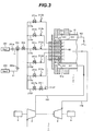
- Fig. 3 is a schematic system diagram of a gas turbine power plant according to the present invention.
- a gaseous fuel supply subsystem 210a and an off gas-exclusive subsystem 210f are employed to form a gaseous fuel supply subsystem for a pilot burner.
- the off gas-exclusive subsystem 210f is dedicated only to the off gas and leads to a burner 51a that is dedicated to the off gas and disposed in a combustor.
- the off gas-exclusive subsystem 210f includes a gaseous fuel flow control valve 211f and an on-off valve 211fa disposed therein.
- the on-off valve 211fa disposed upstream of the gaseous fuel flow control valve 211f prevents fuel leak.
- the gaseous fuel flow control valve 211f and the on-off valve 211fa are connected downstream to a gaseous fuel pressure regulation valve 204 to be shared therebetween.
- a purge subsystem 212f for supplying the fuel piping with purging nitrogen is connected downstream of the gaseous fuel flow control valve 211f.
- operations of up to full load can be performed by adjusting the fuel flow rate of gaseous fuel supply subsystems 210a to 210e according to load.
- Operations involved in changing the fuel type from an LNG 201 to an off gas 202 are basically the same as those in the first example.
- the off gas 202 is supplied to the gaseous fuel supply subsystems 210a, 210b, 210c by adjusting the valve stroke of a three-way transfer valve 203 at a point near 50% load of a gas turbine 1, as will be described later with reference to Fig. 4B .
- the fuel piping downstream of gaseous fuel flow control valves of the gaseous fuel supply subsystems 210d, 210e and the off gas-exclusive subsystem 210f is filled with air.
- purging the piping with a purge subsystem is necessary before the off gas 202 containing nitrogen is to be supplied.
- the off gas-exclusive subsystem 210f the off gas is supplied at point near 50% load of the gas turbine.
- the on-off valve 211fa of the off gas-exclusive subsystem 210f is opened and the gaseous fuel flow control valve 211f is gradually opened, so that the off gas can now be supplied.
- Arranging the off gas-exclusive subsystem 210f in parallel with the five gaseous fuel supply subsystems 210a to 210e permits operations without involving an increased pressure loss of the fuel nozzle when the off gas is supplied.
- the off gas-exclusive subsystem 210f is not to be used. This permits operations without involving the increased pressure loss of the fuel nozzle.
- the on-off valve 211fa of the off gas-exclusive subsystem 210f prevents the LNG from leaking to the off gas-exclusive subsystem 210f during the single fuel combustion of the LNG.
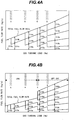
- Figs. 4A and 4B show changes in the fuel flow rate according to the present invention.
- Fig. 4A shows changes in the fuel flow rate when the gas turbine is operated from ignition to full load only with the LNG.
- the off gas-exclusive subsystem 210f is not used and the fuel flow rate follows the same pattern of changes as in Fig. 2A . Details will therefore be omitted.
- Fig. 4B shows a relationship (load operation using the off gas) between the gas turbine load and the fuel flow rate in the present invention.
- the gas turbine is operated with the LNG until the condition of gas turbine load C is reached and the gaseous fuel supply subsystems 210a, 210b, 210c are used to adjust the fuel flow rate according to load.
- the three-way transfer valve is operated to supply the gaseous fuel supply subsystems 210a to 210c with the off gas and the gaseous fuel supply subsystem 210d and the off gas-exclusive subsystem 210f are purged with nitrogen.
- the flow rate of the off gas supplied to the gaseous fuel supply subsystem 210d and the off gas-exclusive subsystem 210f is increased to complete the change of fuel type.
- Fuel is thereafter supplied through the gaseous fuel supply subsystem 210e under the condition of gas turbine load D, so that the combustor can perform high load operations with low NOx combustion through all burner combustion. Understandably, purging must be performed before supplying the gaseous fuel supply subsystem 210e with fuel.
- the off gas-exclusive subsystem 210f included in the gas turbine according to the second embodiment of the present invention eliminates the likelihood of a significant increase in the pressure loss of the fuel nozzle in the gaseous fuel supply subsystem 210a in particular, that is, a subsystem that is shared by the LNG except the off gas-exclusive subsystem 210f.
- Fig. 5 is a schematic system diagram of a gas turbine power plant according to a second example not part of the present invention.
- the second example differs from the first example in that a fuel subsystem leading to a pilot burner is formed by having a gaseous fuel supply subsystem 210a branching into two smaller subsystems.
- the gaseous fuel supply subsystem 210a is branched into a first branch 410a and a second branch 310a at a point downstream thereof.
- the second branch 310a includes a gas shutoff valve 311a disposed therein.
- the gas shutoff valve 311a opens or closes according to the type of fuel and the gas turbine load.
- a pilot burner according to the second example has a larger gas hole area than the pilot burner in the embodiment of the present invention. It is thereby assumed that the gas hole area of the fuel nozzle is adjusted such that the fuel pressure ratio of the fuel nozzle fall within the appropriate value range when the off gas is supplied.
- Figs. 6A and 6B show a relationship between the gas turbine load and the fuel flow rate according to the second example.
- Fig. 6A shows changes in the fuel flow rate under changing loads from 0% load to 100% load in LNG operation.
- the gaseous fuel supply subsystem 210a is branched into the first branch 410a and the second branch 310a and the gas turbine is operated with the gas shutoff valve 311a open under conditions of gas turbine loads A and B.
- the fuel flow rate of the gaseous fuel supply subsystem 210a becomes small after a condition of gas turbine load C is reached.
- the gas turbine is therefore operated by supplying gaseous fuel supply subsystems 210b to 210d with fuel and closing the gas shutoff valve 311a.
- the foregoing operation allows a predetermined fuel pressure ratio of the fuel nozzle to be obtained even under a low flow rate condition of the gaseous fuel supply subsystem 210a as in a condition of gas turbine load C or D.
- the gas hole area of the fuel nozzle communicating with the gaseous fuel supply subsystem 210a is made larger than in the first example and than in the embodiment of the present invention.
- the same fuel flow rate control method as that described earlier applies under high load conditions higher than gas turbine load C.
- Fig. 6B shows changes in the fuel flow rate when the off gas is supplied.
- the gas shutoff valve 311a for the gaseous fuel is closed in a range of gas turbine load C to 100% load, in which the fuel flow rate in the gaseous fuel supply subsystem 210a becomes small.
- the fuel flow rate becomes greater as compared with the LNG and a predetermined fuel pressure ratio in the fuel nozzle can be obtained even in operations with the gas shutoff valve 311a opened.
- the gas turbine is operated with the gas shutoff valve 311a closed only in the range of the gas turbine load C to 100% load in the single fuel combustion of the LNG.
- the gas turbine is operated with the gas shutoff valve 311a open.
Description
- The present invention relates to a gas turbine combustor and a gaseous fuel supply method for the gas turbine combustor.
-
JP-A-2006-161603 JP-A-2006-161603 - In
US 2006/119202 A1 a gas turbine combustor is disclosed. This combustor includes a fuel supply system having a first fuel supply device for supplying a fuel having a large heating value to the combustor, a second fuel supply device for supplying a gas having a small heating value to the combustor, and a switching device operable to switch the first fuel supply device and the second fuel supply device based on a temperature of the air compressed by the air compressor or the exhaust gas discharged from the turbine. - In
US 6 145 297 A , a gas-turbine combustor with a low responsive premix burner is described. The combustor is provided with a plurality of premix burners and a diffusion burner capable of varying the number of the operating premix burners according to the variation of load. - In
US 2007/101720 A1 , a method of operating a fuel system is described. The method includes removing fuel from at least a portion of the fuel system using a gravity drain process. Further, the method includes removing air and nitrogen from at least a portion of the fuel system during a fuel refilling process using a venting process. InJP H07 224688 A - To supply a combustor with the low Btu gas having a lower heating value than LNG, it is necessary to increase the fuel flow rate in proportion to the reduced heating value.
- In
JP-A-2006-161603 - It is an object of the present invention to inhibit a significant increase in cost and unstable combustion resulting due to use of two different types of fuel.
- To achieve the foregoing object, an aspect of the present invention provides a combustor according to
claim 1 and a method according toclaim 4. - In accordance with the aspect of the present invention, use of the two types of gaseous fuels prevents a significant increase in cost and unstable combustion.
- The present invention will be described hereinafter with reference to the accompanying drawings.
-
Fig. 1 is a schematic system diagram of a power plant according to a first example not part of the present invention. -
Figs. 2A and 2B show changes in the flow rate of LNG and off gas under changing gas turbine loads according to the first example. -
Fig. 3 is a schematic system diagram of a power plant according the present invention. -
Figs. 4A and 4B show changes in the flow rate of LNG and off gas under changing gas turbine loads according to the present invention. -
Fig. 5 is a schematic system diagram of a power plant according to a second example not part of the present invention. -
Figs. 6A and 6B show changes in the flow rate of LNG and off gas under changing gas turbine loads according to the second example. - Studies are lately underway on possible use of a large variety of fuel for gas turbines. One study examines the possible use of mixed gas fuel containing multiple components such as hydrogen and carbon monoxide (for example, off gas generated in refineries and coke oven gas generated during steel production processes) as the main fuel for the gas turbine, in addition to the liquefied natural gas (LNG) that is the main fuel of the gas turbine. The mixed gas fuel is a by-product fuel and thus costs low, offering an advantage of reduced running cost of fuel if the fuel can be used for the gas turbine fuel. Moreover, the mixed gas fuel contains hydrogen and, as a result, contains a low carbon content. This could lead to an effect of reduced CO2 in exhaust gases as compared with the LNG.
- Flame temperature resulting from the hydrogen and carbon monoxide contained in such a by-product fuel is, however, higher than that of the LNG. The hydrogen, in particular, has a wide flammability range, a fast burning velocity (easily flammable), and a stronger possibility of explosion. If the hydrogen is to be used as the gas turbine fuel, therefore, common practice is to use an auxiliary fuel for start-up.
- To supply the gas turbine with the high Btu gas (LNG) and the low Btu gas (gas having a lower heating value than the LNG), it is necessary to increase the fuel flow rate in proportion to the reduction in the heating value.
JP-A-2006-161603 JP-A-2006-161603 -
Fig. 1 is a schematic system diagram of a gas turbine power plant according to a first example not part of the present invention. Agas turbine 1 typically includes anair compressor 2, acombustor 3, aturbine 4, agenerator 6, and a start-up motor 8 for driving the gas turbine. - A plurality of
burners 51 for injecting and mixing fuel and air and performing low NOx combustion is disposed at the head portion of thecombustor 3.Combustion air 102 supplied to thecombustor 3 is compressor discharge air compressed by theair compressor 2. Thecombustion air 102 flows through a space defined by a cylindrical liner 3a that forms a combustion chamber and anouter casing 10 that forms a pressure vessel. Thecombustion air 102 thereby cools the surface of the liner 3a and is distributed into cooling air for the liner 3a and combustion air for theburners 51. - The
combustor 3 includes upstream parts offuel supply system 11 supplyingLNG 201 and offgas 202 which contains hydrogen and has a lower heating value than theLNG 201. In the first example, theLNG 201 is the high Btu gas and the offgas 202 is the low Btu gas. A three-way transfer valve (selector valve) 203 is disposed downstream of the two upstream parts offuel supply system 11. The three-way transfer valve 203 permits selection between theLNG 201 and the offgas 202 containing hydrogen. Either one of the gaseous fuel can be supplied by varying the valve stroke of the three-way transfer valve 203. The upstream parts offuel supply system 11 includecheck valves check valves fuel supply system 11. - A single fuel system is disposed downstream of the three-
way transfer valve 203. The fuel system includes a single gaseous fuelpressure regulation valve 204 disposed therein. The gaseous fuelpressure regulation valve 204 regulates the pressure on the upstream side of the gaseous fuel flow control valves 211. The opening of the gaseous fuelpressure regulation valve 204 is adjusted to an appropriate value in accordance with a change in the gaseous fuel flow rate. The arrangement, in which the three-way transfer valve 203 is disposed upstream of the gaseous fuelpressure regulation valve 204, allows the single gaseous fuelpressure regulation valve 204 to be adapted to both types of gaseous fuel. - The fuel system in which the gaseous fuel
pressure regulation valve 204 is disposed is branched on the downstream side thereof into gaseous fuel supply subsystems 210, each corresponding to a corresponding one of theburners 51. The fuel flow rate supplied to theburners 51 can be adjusted with the gaseous fuel flow control valves 211 disposed in the gaseous fuel supply subsystems 210. The gas turbine power plant system shown inFig. 1 includes five subsystems of gaseousfuel supply subsystems 210a to 210e supplying fuel to respective ones of theburners 51. Each of the gaseousfuel supply subsystems 210a to 210e includes a corresponding one of gaseous fuelflow control valves 211a to 211e and a corresponding one ofpurge subsystems 212a to 212e. - Operations of the gas turbine power plant according to the first example will be described below. At start-up, the
gas turbine 1 is driven by the start-upmotor 8 or other external power drive. In thecombustor 3, thecombustion air 102 of theair compressor 2 and theLNG 201 as start-up gaseous fuel are used and theLNG 201 supplied from the gaseousfuel supply subsystem 210a for a pilot burner to theburner 51 is ignited.Combustion gas 110 is thereafter supplied to theturbine 4 and theturbine 4 accelerates as the flow rate of theLNG 201 increases. Thegas turbine 1 enters an autonomous operation mode to reach a no-load full speed when the start-upmotor 8 is disconnected. After thegas turbine 1 has reached the no-load rated speed, thegenerator 6 is put into parallel operation; further, as the fuel flow rate in the gaseousfuel supply subsystem 210a leading to the pilot burner increases, the inlet gas temperature of theturbine 4 increases, and the load increases. Thereafter, the fuel flow rates from gaseousfuel supply subsystems 210b to 210e are sequentially varied to predetermined flow rate conditions using the gaseous fuelflow control valves 211b to 211e. This forms flame in each of allburners 51, enabling continuous load operation in an operable load range through combustion of allburners 51. - The change of fuel between the
LNG 201 and theoff gas 202 containing hydrogen, and load operations of theoff gas 202 according to the first example will be described below. It is herein assumed that the gaseous fuels are changed at a point near 50% load of thegas turbine 1. It is further assumed that theoff gas 202 is the coke oven gas generated at refineries, having a heating value per unit mass lower by about 30% than that of theLNG 201. - The
combustor 3 is ignited and started by supplying theburners 51 with theLNG 201. As the fuel flow rate thereafter increases, theturbine 4 accelerates and the no-load full speed of thegas turbine 1 is reached. After the no-load full speed is reached, the fuel flow rate is sequentially adjusted using the gaseous fuelflow control valves fuel supply subsystems gas turbine 1 being reached. After the partial load condition is reached, the current valve stroke in the three-way transfer valve 203 (fully opened LNG system and fully closed off gas system) is gradually varied so as to achieve the valve stroke in the reverse way. This allows the off gas to be supplied to the gaseousfuel supply subsystems 210a to 210c. Note herein that theLNG 201 flows through the gaseousfuel supply subsystems 210a to 210c; even if the fuel type is changed to theoff gas 202, theoff gas 202 does not coexist with oxygen in the fuel piping, requiring no purge using, for example, nitrogen. The piping downstream of the gaseous fuelflow control valves way transfer valve 203 is completed and the fuel type is changed from theLNG 201 to theoff gas 202, therefore, it becomes necessary to supply nitrogen from thepurge subsystem 212d to purge the piping in order to supply the gaseousfuel supply subsystem 210d with fuel. The change of fuel type is completed by supplying the gaseousfuel supply subsystem 210d with theoff gas 202 after the purging by thepurge subsystem 212d. In addition, if load increases with the increased fuel flow rate, theoff gas 202 is supplied to the gaseousfuel supply subsystem 210e. In this case, too, purging with, for example, nitrogen is necessary in the same manner as with the gaseousfuel supply subsystem 210d. By supplying the gaseousfuel supply subsystem 210e with fuel, flames are formed in allburners 51 disposed in thecombustor 3, enabling continuous load operation with theoff gas 202 through all burner combustion. -
Figs. 2A and 2B show changes in the flow rate of each fuel under changing gas turbine loads.Fig. 2A shows changes in the fuel flow rate in each subsystem from 0% load to full load using only the LNG. InFig. 2A , the abscissa represents gas turbine load and the ordinate represents fuel flow rate. The gas turbine load increases as the total fuel flow rate increases and the fuel flow rate reaches its maximum under the full load condition. The fuel flow rate of each subsystem in the gaseousfuel supply subsystems 210a to 210e is varied according to the load condition so as to change the number of burners to be burned (loads A to D inFig. 2A ). This enables operations from the no-load full speed to full load. Low NOx combustion under high load conditions is enabled by all burner combustion, in which fuel is supplied to all gaseousfuel supply subsystems 210a to 210e. -
Fig. 2B shows changes in the fuel flow rate when the gas turbine is operated with the LNG from ignition and start-up to the partial load condition and the fuel type is thereafter changed from the LNG to the off gas using the three-way transfer valve. Conditions of gas turbine loads A and C are operated with the LNG and the fuel type is changed from the LNG to the off gas under the condition of gas turbine load C. - The off gas has a lower heating value than the LNG. To gain the gas turbine output with the off gas equivalent to that achieved by the LNG, it is necessary to increase the supply fuel flow rate to compensate for the reduced heating value. Specifically, after the fuel type is changed from the LNG to the off gas, there is an increase in the fuel flow rate as compared with the LNG even under the same load condition. When the pressure loss of the fuel nozzle exceeds a permissible value as a result of the increased fuel flow rate, it becomes difficult to supply a required flow rate of the off gas with the same pressure as that applied to the LNG, thus necessitating an increase in the supply pressure. The increased supply pressure calls for changes in specifications of the gas compressor pressure, the control valve or other parts, or fuel piping, leading to a significant increase in cost, as compared with the LNG. Conversely, if the specifications (gas fuel hole area) of the fuel nozzle of the burner are made to comply with the flow rate of the off gas, the pressure loss of the fuel nozzle becomes excessively small under a small flow rate condition for supplying the LNG. Unstable combustion is likely to occur due to deviation of the flow rate. The pressure loss of the fuel nozzle [fuel pressure ratio: (fuel nozzle inlet gas pressure) / (combustor pressure)] should therefore be made to fall within an appropriate range. Special care should be used, in particular, to the gaseous
fuel supply subsystem 210a (pilot burner subsystem) that is operated for the period from ignition of the gas turbine to the full load, because the gaseousfuel supply subsystem 210a has a wide range of fuel flow rate changes. In accordance with the first example, therefore, the change of fuel type between the LNG and the off gas is made under the condition of gas turbine load C. - As described above, if the difference in heating value between two types of fuel is 30% or less, low NOx combustion is possible with the fuels of both the LNG and the off gas under load conditions higher than the condition of gas turbine load C. For a greater difference in the heating value or to reduce the current fuel pressure ratio of the fuel nozzle, the following method is possible.
-
Fig. 3 is a schematic system diagram of a gas turbine power plant according to the present invention. In the present invention, a gaseousfuel supply subsystem 210a and an off gas-exclusive subsystem 210f are employed to form a gaseous fuel supply subsystem for a pilot burner. The off gas-exclusive subsystem 210f is dedicated only to the off gas and leads to aburner 51a that is dedicated to the off gas and disposed in a combustor. The off gas-exclusive subsystem 210f includes a gaseous fuelflow control valve 211f and an on-off valve 211fa disposed therein. The on-off valve 211fa disposed upstream of the gaseous fuelflow control valve 211f prevents fuel leak. The gaseous fuelflow control valve 211f and the on-off valve 211fa are connected downstream to a gaseous fuelpressure regulation valve 204 to be shared therebetween. In addition, apurge subsystem 212f for supplying the fuel piping with purging nitrogen is connected downstream of the gaseous fuelflow control valve 211f. - In single fuel combustion of LNG, operations of up to full load can be performed by adjusting the fuel flow rate of gaseous
fuel supply subsystems 210a to 210e according to load. Operations involved in changing the fuel type from anLNG 201 to an offgas 202 are basically the same as those in the first example. In the present invention, theoff gas 202 is supplied to the gaseousfuel supply subsystems way transfer valve 203 at a point near 50% load of agas turbine 1, as will be described later with reference toFig. 4B . At this time, the fuel piping downstream of gaseous fuel flow control valves of the gaseousfuel supply subsystems exclusive subsystem 210f is filled with air. As a result, purging the piping with a purge subsystem is necessary before theoff gas 202 containing nitrogen is to be supplied. In the off gas-exclusive subsystem 210f, the off gas is supplied at point near 50% load of the gas turbine. After the purging of the piping is completed, the on-off valve 211fa of the off gas-exclusive subsystem 210f is opened and the gaseous fuelflow control valve 211f is gradually opened, so that the off gas can now be supplied. Arranging the off gas-exclusive subsystem 210f in parallel with the five gaseousfuel supply subsystems 210a to 210e permits operations without involving an increased pressure loss of the fuel nozzle when the off gas is supplied. In addition, during the single fuel combustion of the LNG, the off gas-exclusive subsystem 210f is not to be used. This permits operations without involving the increased pressure loss of the fuel nozzle. Note that the on-off valve 211fa of the off gas-exclusive subsystem 210f prevents the LNG from leaking to the off gas-exclusive subsystem 210f during the single fuel combustion of the LNG. -
Figs. 4A and 4B show changes in the fuel flow rate according to the present invention.Fig. 4A shows changes in the fuel flow rate when the gas turbine is operated from ignition to full load only with the LNG. When the LNG only is used, the off gas-exclusive subsystem 210f is not used and the fuel flow rate follows the same pattern of changes as inFig. 2A . Details will therefore be omitted. -
Fig. 4B shows a relationship (load operation using the off gas) between the gas turbine load and the fuel flow rate in the present invention. The gas turbine is operated with the LNG until the condition of gas turbine load C is reached and the gaseousfuel supply subsystems fuel supply subsystems 210a to 210c with the off gas and the gaseousfuel supply subsystem 210d and the off gas-exclusive subsystem 210f are purged with nitrogen. After the purging, the flow rate of the off gas supplied to the gaseousfuel supply subsystem 210d and the off gas-exclusive subsystem 210f is increased to complete the change of fuel type. Fuel is thereafter supplied through the gaseousfuel supply subsystem 210e under the condition of gas turbine load D, so that the combustor can perform high load operations with low NOx combustion through all burner combustion. Understandably, purging must be performed before supplying the gaseousfuel supply subsystem 210e with fuel. The off gas-exclusive subsystem 210f included in the gas turbine according to the second embodiment of the present invention eliminates the likelihood of a significant increase in the pressure loss of the fuel nozzle in the gaseousfuel supply subsystem 210a in particular, that is, a subsystem that is shared by the LNG except the off gas-exclusive subsystem 210f. -
Fig. 5 is a schematic system diagram of a gas turbine power plant according to a second example not part of the present invention. The second example differs from the first example in that a fuel subsystem leading to a pilot burner is formed by having a gaseousfuel supply subsystem 210a branching into two smaller subsystems. Specifically, the gaseousfuel supply subsystem 210a is branched into a first branch 410a and asecond branch 310a at a point downstream thereof. Thesecond branch 310a includes agas shutoff valve 311a disposed therein. Thegas shutoff valve 311a opens or closes according to the type of fuel and the gas turbine load. A pilot burner according to the second example has a larger gas hole area than the pilot burner in the embodiment of the present invention. It is thereby assumed that the gas hole area of the fuel nozzle is adjusted such that the fuel pressure ratio of the fuel nozzle fall within the appropriate value range when the off gas is supplied. -
Figs. 6A and 6B show a relationship between the gas turbine load and the fuel flow rate according to the second example.Fig. 6A shows changes in the fuel flow rate under changing loads from 0% load to 100% load in LNG operation. The gaseousfuel supply subsystem 210a is branched into the first branch 410a and thesecond branch 310a and the gas turbine is operated with thegas shutoff valve 311a open under conditions of gas turbine loads A and B. The fuel flow rate of the gaseousfuel supply subsystem 210a becomes small after a condition of gas turbine load C is reached. The gas turbine is therefore operated by supplying gaseousfuel supply subsystems 210b to 210d with fuel and closing thegas shutoff valve 311a. The foregoing operation allows a predetermined fuel pressure ratio of the fuel nozzle to be obtained even under a low flow rate condition of the gaseousfuel supply subsystem 210a as in a condition of gas turbine load C or D. In this case, the gas hole area of the fuel nozzle communicating with the gaseousfuel supply subsystem 210a is made larger than in the first example and than in the embodiment of the present invention. The same fuel flow rate control method as that described earlier applies under high load conditions higher than gas turbine load C. -
Fig. 6B shows changes in the fuel flow rate when the off gas is supplied. In single fuel combustion of the LNG, thegas shutoff valve 311a for the gaseous fuel is closed in a range of gas turbine load C to 100% load, in which the fuel flow rate in the gaseousfuel supply subsystem 210a becomes small. With the off gas, the fuel flow rate becomes greater as compared with the LNG and a predetermined fuel pressure ratio in the fuel nozzle can be obtained even in operations with thegas shutoff valve 311a opened. Specifically, the gas turbine is operated with thegas shutoff valve 311a closed only in the range of the gas turbine load C to 100% load in the single fuel combustion of the LNG. In any other gas turbine load and fuel type conditions, the gas turbine is operated with thegas shutoff valve 311a open. Through the foregoing operations, an appropriate pressure for the fuel nozzle can be achieved for either type of the gaseous fuel, enabling low NOx operations.
Claims (4)
- A combustor (3), comprising:two upstream parts (201, 201a; 202, 202a) of a fuel supply system (11) for supplying gaseous fuels of two types (201; 202) having different heating values from each other;a three-way fuel transfer valve (203) for merging the two upstream parts (201, 201a; 202, 202a) of the fuel supply system (11) with each other;a plurality of gaseous fuel supply subsystems (210) for supplying a combustion chamber with the gaseous fuels supplied through the three-way fuel transfer valve (203);a plurality of burners (51) for injecting, corresponding to each of the gaseous fuel supply subsystems (210a-210e), the gaseous fuel supplied from the gaseous fuel supply subsystem (210) into the combustion chamber;characterized in thata low Btu gas-exclusive subsystem (210f) disposed in parallel with the gaseous fuel supply subsystems (210a-210e); anda burner (51a) for injecting the low Btu gas supplied from the low Btu gas-exclusive subsystem (210f) into the combustion chamber, wherein:the low Btu gas-exclusive subsystem (210f) includes:a gaseous fuel flow control valve (211f) for adjusting the flow rate of the low Btu gas;a gas shutoff valve (211fa), disposed upstream of the gaseous fuel flow control valve (211f), for preventing a high Btu gas from leaking to the low Btu gas-exclusive subsystem (210f) during the single fuel combustion of the high Btu gas; anda purge subsystem (212f) disposed downstream of the gaseous fuel flow control valve (211f).
- The combustor (3) according to claim 1, comprising:a gaseous fuel pressure regulation valve (204) for regulating the pressure of the gaseous fuels supplied through the three-way fuel transfer valve (203); anda gaseous fuel flow control valve (211a-211e) disposed in each of the gaseous fuel supply subsystems (210a-210e), the gaseous fuel flow control valve (211a-211e) being adapted to adjust the gaseous fuel flow rate; whereinthe plurality of gaseous fuel supply subsystems (210) supply the combustion chamber with the gaseous fuels supplied through the gaseous fuel pressure regulation valve (204).
- The combustor according to claim 1 or 2, wherein:one of the gaseous fuels is liquefied natural gas (LNG) (201) and the other of the gaseous fuels is off gas (202) generated, for example, in refineries, the off gas having a lower heating value than the LNG, or coke oven gas generated during steel production processes, or other mixed gas containing hydrogen or carbon monoxide.
- A method for operating a combustor (3), the combustor (3) comprising:two upstream parts (201, 201a; 202, 202a) of a fuel supply system (11) for supplying gaseous fuels of two types (201; 202) having different heating values from each other;a three-way fuel transfer valve (203) for merging the two upstream parts (201, 201a; 202, 202a) of the fuel supply system (11) with each other;a plurality of gaseous fuel supply subsystems (210) for supplying a combustion chamber with the gaseous fuels supplied through the three-way fuel transfer valve (203) and branched;a plurality of burners (51) for injecting, corresponding to each of the gaseous fuel supply subsystems (210a-210e), the gaseous fuel supplied from the gaseous fuel supply subsystem (210) into the combustion chamber;a low Btu gas-exclusive subsystem (210f) disposed in parallel with the gaseous fuel supply subsystems (210a-210e); anda burner (51a) for injecting the low Btu gas supplied from the low Btu gas-exclusive subsystem (210f) into the combustion chamber, wherein:the low Btu gas-exclusive subsystem (210f) includes:a gaseous fuel flow control valve (211f) for adjusting the flow rate of the low Btu gas;a gas shutoff valve (211fa), disposed upstream of the gaseous fuel flow control valve (211f), for preventing a high Btu gas from leaking to the low Btu gas-exclusive subsystem (210f) during the single fuel combustion of the high Btu gas; anda purge subsystem (212f) disposed downstream of the gaseous fuel flow control valve (211f),the method comprising the steps of:operating with, of the gaseous fuels of two types (201; 202), a gaseous fuel having a higher heating value for a period from ignition and start-up, andthereafter changing the position of the three-way transfer valve (203) so as to operate with a gaseous fuel having a lower heating value and increasing the number of burners (51) supplied with the gaseous fuel.
Applications Claiming Priority (1)
| Application Number | Priority Date | Filing Date | Title |
|---|---|---|---|
| JP2008054230A JP4979615B2 (en) | 2008-03-05 | 2008-03-05 | Combustor and fuel supply method for combustor |
Publications (3)
| Publication Number | Publication Date |
|---|---|
| EP2098785A2 EP2098785A2 (en) | 2009-09-09 |
| EP2098785A3 EP2098785A3 (en) | 2016-05-11 |
| EP2098785B1 true EP2098785B1 (en) | 2018-11-28 |
Family
ID=40740080
Family Applications (1)
| Application Number | Title | Priority Date | Filing Date |
|---|---|---|---|
| EP09002188.2A Active EP2098785B1 (en) | 2008-03-05 | 2009-02-17 | Gas turbine combustor and gaseous fuel supply method for gas turbine combustor |
Country Status (5)
| Country | Link |
|---|---|
| US (1) | US8261529B2 (en) |
| EP (1) | EP2098785B1 (en) |
| JP (1) | JP4979615B2 (en) |
| CN (1) | CN101526217B (en) |
| HK (1) | HK1136025A1 (en) |
Families Citing this family (34)
| Publication number | Priority date | Publication date | Assignee | Title |
|---|---|---|---|---|
| US20110036092A1 (en) * | 2009-08-12 | 2011-02-17 | General Electric Company | Methods and Systems for Dry Low NOx Combustion Systems |
| JP5159741B2 (en) * | 2009-09-30 | 2013-03-13 | 株式会社日立製作所 | Control device for gas turbine combustor and control method for gas turbine combustor |
| JP5075900B2 (en) * | 2009-09-30 | 2012-11-21 | 株式会社日立製作所 | Hydrogen-containing fuel compatible combustor and its low NOx operation method |
| JP5084847B2 (en) * | 2010-01-13 | 2012-11-28 | 株式会社日立製作所 | Gas turbine combustor |
| MY156099A (en) * | 2010-07-02 | 2016-01-15 | Exxonmobil Upstream Res Co | Systems and methods for controlling combustion of a fuel |
| JP5529676B2 (en) * | 2010-08-20 | 2014-06-25 | 三菱重工業株式会社 | Fuel supply system for gas turbine combustor and fuel supply method for gas turbine combustor |
| US9360219B2 (en) * | 2010-12-30 | 2016-06-07 | Rolls-Royce North American Technologies, Inc. | Supercritical or mixed phase multi-port fuel injector |
| CN102221209A (en) * | 2011-04-15 | 2011-10-19 | 上海宝钢工业检测公司 | Single-control multi-jet spray composite jet flow flame regulating burner for expanding temperature field |
| JP5458121B2 (en) * | 2012-01-27 | 2014-04-02 | 株式会社日立製作所 | Gas turbine combustor and method of operating gas turbine combustor |
| JP5889754B2 (en) * | 2012-09-05 | 2016-03-22 | 三菱日立パワーシステムズ株式会社 | Gas turbine combustor |
| US20150184858A1 (en) * | 2012-10-01 | 2015-07-02 | Peter John Stuttford | Method of operating a multi-stage flamesheet combustor |
| US9353691B2 (en) * | 2012-12-18 | 2016-05-31 | General Electric Company | Fuel routing system of a gas turbine engine and method of routing fuel |
| US20150337730A1 (en) * | 2012-12-28 | 2015-11-26 | General Electric Company | Turbine engine assemblies |
| US9377202B2 (en) | 2013-03-15 | 2016-06-28 | General Electric Company | System and method for fuel blending and control in gas turbines |
| US9382850B2 (en) | 2013-03-21 | 2016-07-05 | General Electric Company | System and method for controlled fuel blending in gas turbines |
| JP6021705B2 (en) * | 2013-03-22 | 2016-11-09 | 三菱重工業株式会社 | Combustor and gas turbine |
| US9903588B2 (en) * | 2013-07-30 | 2018-02-27 | General Electric Company | System and method for barrier in passage of combustor of gas turbine engine with exhaust gas recirculation |
| JP6190670B2 (en) * | 2013-08-30 | 2017-08-30 | 三菱日立パワーシステムズ株式会社 | Gas turbine combustion system |
| CN103715061B (en) * | 2013-12-31 | 2016-01-27 | 詹云翔 | A kind of sintering mouth of bulb sealing machine |
| US20160326905A1 (en) * | 2014-01-09 | 2016-11-10 | General Electric Company | Vibration damping assembly for a piping unit |
| FR3018561B1 (en) * | 2014-03-12 | 2017-05-26 | Ge Energy Products France Snc | METHOD FOR MONITORING THE OPERATION OF VALVES OF A GAS TURBINE GAS SUPPLY DEVICE |
| CN106170617A (en) * | 2014-03-31 | 2016-11-30 | 西门子公司 | Pressure-regulating device for the air supply system of gas-turbine plant |
| JP6343504B2 (en) * | 2014-07-03 | 2018-06-13 | 三菱日立パワーシステムズ株式会社 | 2-shaft gas turbine |
| WO2017005694A1 (en) | 2015-07-06 | 2017-01-12 | Siemens Aktiengesellschaft | Burner for a gas turbine and method for operating the burner |
| JP6651389B2 (en) * | 2016-03-08 | 2020-02-19 | 三菱日立パワーシステムズ株式会社 | Fuel control device, combustor, gas turbine, fuel control method and program |
| US10634358B2 (en) * | 2017-06-16 | 2020-04-28 | General Electric Company | System and method for igniting liquid fuel in a gas turbine combustor |
| CN110735718A (en) * | 2019-08-20 | 2020-01-31 | 南京理工大学 | Fuel supply gear adjusting device of liquid ramjet engine |
| US20210207541A1 (en) * | 2020-01-08 | 2021-07-08 | United Technologies Corporation | Method of using a primary fuel to pilot liquid fueled combustors |
| US11326521B2 (en) | 2020-06-30 | 2022-05-10 | General Electric Company | Methods of igniting liquid fuel in a turbomachine |
| US11346281B2 (en) * | 2020-08-21 | 2022-05-31 | Woodward, Inc. | Dual schedule flow divider valve, system, and method for use therein |
| JP2022141048A (en) * | 2021-03-15 | 2022-09-29 | 本田技研工業株式会社 | Fuel feed system |
| US11808219B2 (en) | 2021-04-12 | 2023-11-07 | Pratt & Whitney Canada Corp. | Fuel systems and methods for purging |
| US20230036266A1 (en) * | 2021-07-27 | 2023-02-02 | Pratt & Whitney Canada Corp. | Controlling gaseous fuel flow |
| WO2023140183A1 (en) * | 2022-01-20 | 2023-07-27 | 三菱重工業株式会社 | Control method for gas turbine combustor and control device for gas turbine combustor |
Family Cites Families (32)
| Publication number | Priority date | Publication date | Assignee | Title |
|---|---|---|---|---|
| US4039804A (en) * | 1972-03-14 | 1977-08-02 | Westinghouse Electric Corporation | System and method for monitoring industrial gas turbine operating parameters and for providing gas turbine power plant control system inputs representative thereof |
| US4025282A (en) * | 1975-05-21 | 1977-05-24 | John Zink Company | Apparatus to burn liquid fuels in a gaseous fuel burner |
| US4369803A (en) * | 1981-01-28 | 1983-01-25 | Phillips Petroleum Company | Control of fuel gas blending |
| JPS6057131A (en) * | 1983-09-08 | 1985-04-02 | Hitachi Ltd | Fuel feeding process for gas turbine combustor |
| JPS61241425A (en) * | 1985-04-17 | 1986-10-27 | Hitachi Ltd | Fuel gas controlling method of gas turbine and controller |
| JPH063148B2 (en) * | 1986-03-19 | 1994-01-12 | 株式会社日立製作所 | Dual gas fuel fired gas turbine fuel control system |
| JPS62180217U (en) * | 1986-04-30 | 1987-11-16 | ||
| US4761948A (en) | 1987-04-09 | 1988-08-09 | Solar Turbines Incorporated | Wide range gaseous fuel combustion system for gas turbine engines |
| JP2856860B2 (en) | 1990-07-31 | 1999-02-10 | 株式会社東芝 | Gas turbine equipment |
| JPH07224688A (en) * | 1994-02-09 | 1995-08-22 | Mitsubishi Heavy Ind Ltd | Fuel supply method for gas turbine |
| JP3188140B2 (en) | 1995-05-12 | 2001-07-16 | 三菱重工業株式会社 | Multi-nozzle combustor for gas turbine and control method therefor |
| US6092362A (en) * | 1996-11-27 | 2000-07-25 | Hitachi, Ltd. | Gas-turbine combustor with load-responsive premix burners |
| EP0915242B1 (en) | 1997-11-04 | 2003-09-03 | Hitachi, Ltd. | Gas turbine |
| JP3788071B2 (en) * | 1997-11-04 | 2006-06-21 | 株式会社日立製作所 | gas turbine |
| EP0952317A3 (en) * | 1998-04-21 | 2002-04-17 | Mitsubishi Heavy Industries, Ltd. | Purging system for a gas turbine fuel supply |
| EP1199453A3 (en) * | 1998-05-08 | 2003-01-22 | Mitsubishi Heavy Industries, Ltd. | Gas turbine fuel nozzle wash system |
| WO2000014451A1 (en) * | 1998-09-10 | 2000-03-16 | Siemens Aktiengesellschaft | Method for operating a burner and burner arrangement |
| US6385960B1 (en) * | 1999-10-14 | 2002-05-14 | General Electric Company | Methods and apparatus for operation of gas turbines |
| EP1277920A1 (en) * | 2001-07-19 | 2003-01-22 | Siemens Aktiengesellschaft | Procedure for operating a combuster of a gas-turbine and power plant |
| JP3960166B2 (en) | 2001-08-29 | 2007-08-15 | 株式会社日立製作所 | Gas turbine combustor and operation method of gas turbine combustor |
| US6640548B2 (en) * | 2001-09-26 | 2003-11-04 | Siemens Westinghouse Power Corporation | Apparatus and method for combusting low quality fuel |
| JP2003328779A (en) * | 2002-05-10 | 2003-11-19 | Mitsubishi Heavy Ind Ltd | Fuel supply system and air-fuel ratio adjusting method for gas turbine and gas turbine |
| UA78460C2 (en) * | 2003-06-13 | 2007-03-15 | Kawasaki Heavy Ind Ltd | Electric power supply system |
| JP2006161603A (en) * | 2004-12-03 | 2006-06-22 | Ebara Corp | Gas turbine device and gas turbine power generation system |
| US7464555B2 (en) * | 2005-05-05 | 2008-12-16 | Siemens Energy, Inc. | Catalytic combustor for integrated gasification combined cycle power plant |
| JP4486549B2 (en) | 2005-06-06 | 2010-06-23 | 三菱重工業株式会社 | Gas turbine combustor |
| JP2007046843A (en) * | 2005-08-10 | 2007-02-22 | Hitachi Ltd | Gas turbine combustor and method for remodeling gas turbine combustor |
| JP4119908B2 (en) * | 2005-09-14 | 2008-07-16 | 三菱重工業株式会社 | Combustion control device for gas turbine |
| US7721521B2 (en) * | 2005-11-07 | 2010-05-25 | General Electric Company | Methods and apparatus for a combustion turbine fuel recirculation system and nitrogen purge system |
| US7549293B2 (en) * | 2006-02-15 | 2009-06-23 | General Electric Company | Pressure control method to reduce gas turbine fuel supply pressure requirements |
| US7644574B2 (en) * | 2006-08-15 | 2010-01-12 | General Electric Company | Methods and systems for gas turbine engine control |
| US7921651B2 (en) * | 2008-05-05 | 2011-04-12 | General Electric Company | Operation of dual gas turbine fuel system |
-
2008
- 2008-03-05 JP JP2008054230A patent/JP4979615B2/en active Active
-
2009
- 2009-02-12 US US12/370,236 patent/US8261529B2/en active Active
- 2009-02-17 EP EP09002188.2A patent/EP2098785B1/en active Active
- 2009-02-18 CN CN2009100042643A patent/CN101526217B/en active Active
-
2010
- 2010-01-15 HK HK10100485.0A patent/HK1136025A1/en unknown
Non-Patent Citations (1)
| Title |
|---|
| None * |
Also Published As
| Publication number | Publication date |
|---|---|
| US20090223226A1 (en) | 2009-09-10 |
| CN101526217B (en) | 2011-06-01 |
| JP4979615B2 (en) | 2012-07-18 |
| JP2009210200A (en) | 2009-09-17 |
| CN101526217A (en) | 2009-09-09 |
| EP2098785A3 (en) | 2016-05-11 |
| US8261529B2 (en) | 2012-09-11 |
| HK1136025A1 (en) | 2010-06-18 |
| EP2098785A2 (en) | 2009-09-09 |
Similar Documents
| Publication | Publication Date | Title |
|---|---|---|
| EP2098785B1 (en) | Gas turbine combustor and gaseous fuel supply method for gas turbine combustor | |
| KR101888790B1 (en) | Gas turbine combustor | |
| US9052115B2 (en) | System and method for supplying a working fluid to a combustor | |
| JP6190670B2 (en) | Gas turbine combustion system | |
| JP4728176B2 (en) | Burner, gas turbine combustor and burner cooling method | |
| JP5075900B2 (en) | Hydrogen-containing fuel compatible combustor and its low NOx operation method | |
| KR101586216B1 (en) | Gas turbine with improved part load emissions behavior | |
| US8499541B2 (en) | Method for starting premixed combustion in combustor for two-shaft gas turbine | |
| US9631559B2 (en) | Fuel control method and fuel control apparatus for gas turbine and gas turbine | |
| US9739488B2 (en) | Gas turbine combustor with two kinds of gas fuel supply systems | |
| JP5063538B2 (en) | Gas turbine fuel supply method | |
| JP6253066B2 (en) | Method of partial load CO reduction operation and gas turbine for a two-stage combustion gas turbine | |
| JP2010276021A (en) | Gas turbine combustion system with in-line fuel reforming and method for use thereof | |
| KR20150039107A (en) | Gas turbine with sequential combustion arrangement | |
| WO2015102882A1 (en) | Systems and methods to maintain stability of fuel flow in gas turbine engines | |
| EP2620621A2 (en) | Gas turbine engine system and method for controlling a temperature of a conduit in a gas turbine engine system | |
| JP5843578B2 (en) | Gas mixture supply system | |
| US20240026814A1 (en) | Combustion device and gas turbine system | |
| JP2002201966A (en) | Premixing combustor for gas turbine and its fuel supply control method | |
| JP2012122421A (en) | Gas turbine system and humidification control method | |
| WO2023179911A1 (en) | Firing apparatus and firing method for high reactive fuel gases | |
| KR20220123232A (en) | Control unit for steam generator | |
| JPH039032A (en) | Fuel feeding control device for gas turbine |
Legal Events
| Date | Code | Title | Description |
|---|---|---|---|
| PUAI | Public reference made under article 153(3) epc to a published international application that has entered the european phase |
Free format text: ORIGINAL CODE: 0009012 |
|
| 17P | Request for examination filed |
Effective date: 20090710 |
|
| AK | Designated contracting states |
Kind code of ref document: A2 Designated state(s): AT BE BG CH CY CZ DE DK EE ES FI FR GB GR HR HU IE IS IT LI LT LU LV MC MK MT NL NO PL PT RO SE SI SK TR |
|
| AX | Request for extension of the european patent |
Extension state: AL BA RS |
|
| RAP1 | Party data changed (applicant data changed or rights of an application transferred) |
Owner name: MITSUBISHI HITACHI POWER SYSTEMS, LTD. |
|
| RAP1 | Party data changed (applicant data changed or rights of an application transferred) |
Owner name: MITSUBISHI HITACHI POWER SYSTEMS, LTD. |
|
| PUAL | Search report despatched |
Free format text: ORIGINAL CODE: 0009013 |
|
| AK | Designated contracting states |
Kind code of ref document: A3 Designated state(s): AT BE BG CH CY CZ DE DK EE ES FI FR GB GR HR HU IE IS IT LI LT LU LV MC MK MT NL NO PL PT RO SE SI SK TR |
|
| AX | Request for extension of the european patent |
Extension state: AL BA RS |
|
| RIC1 | Information provided on ipc code assigned before grant |
Ipc: F23R 3/36 20060101AFI20160401BHEP |
|
| AKX | Designation fees paid |
Designated state(s): DE FR GB SE |
|
| AXX | Extension fees paid |
Extension state: BA Extension state: RS Extension state: AL |
|
| 17Q | First examination report despatched |
Effective date: 20180216 |
|
| REG | Reference to a national code |
Ref country code: DE Ref legal event code: R079 Ref document number: 602009055866 Country of ref document: DE Free format text: PREVIOUS MAIN CLASS: F23R0003360000 Ipc: F02C0003220000 |
|
| GRAP | Despatch of communication of intention to grant a patent |
Free format text: ORIGINAL CODE: EPIDOSNIGR1 |
|
| RIC1 | Information provided on ipc code assigned before grant |
Ipc: F02C 7/22 20060101ALI20180604BHEP Ipc: F02C 3/22 20060101AFI20180604BHEP Ipc: F23R 3/36 20060101ALI20180604BHEP Ipc: F02C 7/232 20060101ALI20180604BHEP |
|
| INTG | Intention to grant announced |
Effective date: 20180628 |
|
| GRAS | Grant fee paid |
Free format text: ORIGINAL CODE: EPIDOSNIGR3 |
|
| GRAA | (expected) grant |
Free format text: ORIGINAL CODE: 0009210 |
|
| AK | Designated contracting states |
Kind code of ref document: B1 Designated state(s): DE FR GB SE |
|
| REG | Reference to a national code |
Ref country code: GB Ref legal event code: FG4D |
|
| RIN1 | Information on inventor provided before grant (corrected) |
Inventor name: NISHIJAMA, TSUNEMASA Inventor name: MURATA, HIDETARO Inventor name: KOIZUMI, HIROMI Inventor name: ASAI, TOMOHIRO Inventor name: INOUE, HIROSHI |
|
| REG | Reference to a national code |
Ref country code: DE Ref legal event code: R096 Ref document number: 602009055866 Country of ref document: DE |
|
| PG25 | Lapsed in a contracting state [announced via postgrant information from national office to epo] |
Ref country code: SE Free format text: LAPSE BECAUSE OF FAILURE TO SUBMIT A TRANSLATION OF THE DESCRIPTION OR TO PAY THE FEE WITHIN THE PRESCRIBED TIME-LIMIT Effective date: 20181128 |
|
| REG | Reference to a national code |
Ref country code: DE Ref legal event code: R097 Ref document number: 602009055866 Country of ref document: DE |
|
| PLBE | No opposition filed within time limit |
Free format text: ORIGINAL CODE: 0009261 |
|
| STAA | Information on the status of an ep patent application or granted ep patent |
Free format text: STATUS: NO OPPOSITION FILED WITHIN TIME LIMIT |
|
| 26N | No opposition filed |
Effective date: 20190829 |
|
| REG | Reference to a national code |
Ref country code: DE Ref legal event code: R082 Ref document number: 602009055866 Country of ref document: DE Representative=s name: MERH-IP MATIAS ERNY REICHL HOFFMANN PATENTANWA, DE Ref country code: DE Ref legal event code: R081 Ref document number: 602009055866 Country of ref document: DE Owner name: MITSUBISHI POWER, LTD., JP Free format text: FORMER OWNER: MITSUBISHI HITACHI POWER SYSTEMS, LTD., YOKOHAMA, JP |
|
| PGFP | Annual fee paid to national office [announced via postgrant information from national office to epo] |
Ref country code: FR Payment date: 20220118 Year of fee payment: 14 |
|
| PGFP | Annual fee paid to national office [announced via postgrant information from national office to epo] |
Ref country code: GB Payment date: 20221230 Year of fee payment: 15 |
|
| PGFP | Annual fee paid to national office [announced via postgrant information from national office to epo] |
Ref country code: DE Payment date: 20221229 Year of fee payment: 15 |