EP4324758A1 - A packed roof window product and a method for packing a roof window product - Google Patents
A packed roof window product and a method for packing a roof window product Download PDFInfo
- Publication number
- EP4324758A1 EP4324758A1 EP23192098.4A EP23192098A EP4324758A1 EP 4324758 A1 EP4324758 A1 EP 4324758A1 EP 23192098 A EP23192098 A EP 23192098A EP 4324758 A1 EP4324758 A1 EP 4324758A1
- Authority
- EP
- European Patent Office
- Prior art keywords
- box
- internal
- component
- roof window
- components
- Prior art date
- Legal status (The legal status is an assumption and is not a legal conclusion. Google has not performed a legal analysis and makes no representation as to the accuracy of the status listed.)
- Pending
Links
Images



Classifications
-
- B—PERFORMING OPERATIONS; TRANSPORTING
- B65—CONVEYING; PACKING; STORING; HANDLING THIN OR FILAMENTARY MATERIAL
- B65D—CONTAINERS FOR STORAGE OR TRANSPORT OF ARTICLES OR MATERIALS, e.g. BAGS, BARRELS, BOTTLES, BOXES, CANS, CARTONS, CRATES, DRUMS, JARS, TANKS, HOPPERS, FORWARDING CONTAINERS; ACCESSORIES, CLOSURES, OR FITTINGS THEREFOR; PACKAGING ELEMENTS; PACKAGES
- B65D85/00—Containers, packaging elements or packages, specially adapted for particular articles or materials
- B65D85/30—Containers, packaging elements or packages, specially adapted for particular articles or materials for articles particularly sensitive to damage by shock or pressure
- B65D85/46—Containers, packaging elements or packages, specially adapted for particular articles or materials for articles particularly sensitive to damage by shock or pressure for bricks, tiles or building blocks
-
- B—PERFORMING OPERATIONS; TRANSPORTING
- B65—CONVEYING; PACKING; STORING; HANDLING THIN OR FILAMENTARY MATERIAL
- B65D—CONTAINERS FOR STORAGE OR TRANSPORT OF ARTICLES OR MATERIALS, e.g. BAGS, BARRELS, BOTTLES, BOXES, CANS, CARTONS, CRATES, DRUMS, JARS, TANKS, HOPPERS, FORWARDING CONTAINERS; ACCESSORIES, CLOSURES, OR FITTINGS THEREFOR; PACKAGING ELEMENTS; PACKAGES
- B65D25/00—Details of other kinds or types of rigid or semi-rigid containers
- B65D25/02—Internal fittings
- B65D25/10—Devices to locate articles in containers
-
- B—PERFORMING OPERATIONS; TRANSPORTING
- B65—CONVEYING; PACKING; STORING; HANDLING THIN OR FILAMENTARY MATERIAL
- B65D—CONTAINERS FOR STORAGE OR TRANSPORT OF ARTICLES OR MATERIALS, e.g. BAGS, BARRELS, BOTTLES, BOXES, CANS, CARTONS, CRATES, DRUMS, JARS, TANKS, HOPPERS, FORWARDING CONTAINERS; ACCESSORIES, CLOSURES, OR FITTINGS THEREFOR; PACKAGING ELEMENTS; PACKAGES
- B65D51/00—Closures not otherwise provided for
- B65D51/24—Closures not otherwise provided for combined or co-operating with auxiliary devices for non-closing purposes
- B65D51/26—Closures not otherwise provided for combined or co-operating with auxiliary devices for non-closing purposes with means for keeping contents in position, e.g. resilient means
-
- B—PERFORMING OPERATIONS; TRANSPORTING
- B65—CONVEYING; PACKING; STORING; HANDLING THIN OR FILAMENTARY MATERIAL
- B65D—CONTAINERS FOR STORAGE OR TRANSPORT OF ARTICLES OR MATERIALS, e.g. BAGS, BARRELS, BOTTLES, BOXES, CANS, CARTONS, CRATES, DRUMS, JARS, TANKS, HOPPERS, FORWARDING CONTAINERS; ACCESSORIES, CLOSURES, OR FITTINGS THEREFOR; PACKAGING ELEMENTS; PACKAGES
- B65D77/00—Packages formed by enclosing articles or materials in preformed containers, e.g. boxes, cartons, sacks or bags
- B65D77/22—Details
- B65D77/24—Inserts or accessories added or incorporated during filling of containers
- B65D77/26—Elements or devices for locating or protecting articles
-
- B—PERFORMING OPERATIONS; TRANSPORTING
- B65—CONVEYING; PACKING; STORING; HANDLING THIN OR FILAMENTARY MATERIAL
- B65D—CONTAINERS FOR STORAGE OR TRANSPORT OF ARTICLES OR MATERIALS, e.g. BAGS, BARRELS, BOTTLES, BOXES, CANS, CARTONS, CRATES, DRUMS, JARS, TANKS, HOPPERS, FORWARDING CONTAINERS; ACCESSORIES, CLOSURES, OR FITTINGS THEREFOR; PACKAGING ELEMENTS; PACKAGES
- B65D2313/00—Connecting or fastening means
- B65D2313/08—Double sided adhesive tape, e.g. for suspension of the container
-
- B—PERFORMING OPERATIONS; TRANSPORTING
- B65—CONVEYING; PACKING; STORING; HANDLING THIN OR FILAMENTARY MATERIAL
- B65D—CONTAINERS FOR STORAGE OR TRANSPORT OF ARTICLES OR MATERIALS, e.g. BAGS, BARRELS, BOTTLES, BOXES, CANS, CARTONS, CRATES, DRUMS, JARS, TANKS, HOPPERS, FORWARDING CONTAINERS; ACCESSORIES, CLOSURES, OR FITTINGS THEREFOR; PACKAGING ELEMENTS; PACKAGES
- B65D2313/00—Connecting or fastening means
- B65D2313/10—Adhesive or cohesive means for holding the contents attached to the container
Definitions
- the present invention relates to a packed roof window product comprising a plurality of differently sized roof window related components accommodated in a box, wherein the box has a bottom side and a top side, which are spaced apart along a height axis, and side walls, which extend between the bottom side and top side of the box along the height axis, and where the bottom side, top side and side walls delimit an internal space of the box, which internal space accommodates the components, where the bottom side has an internal bottom surface, the top side has an internal top surface, and each side wall has an internal side surface, which internal bottom, top and side surfaces each face the internal space of the box, and where a first of said components is supported by the internal bottom surface.
- roof window products such as the roof window itself or a flashing assembly for a roof window
- the components are typically arranged in the box in an intended order of use and small components, such as screws, are kept in plastic bags.
- packaging material components such as blocks of expanded polystyrene or similar shock absorbing material are used for protecting the product and/or for keeping the components in the intended position within the box.
- An example of a packed roof window, where these principles are used, is known from EP2748071B1
- an example of a packed flashing assembly for a roof window is known from EP1710163B1 .
- small components have been attached to the box or to larger components, for example by means of an adhesive, to prevent them from becoming lost, either inside the box or when removed from the box, and/or they have been wrapped in plastic, thereby also preventing them from scratching or otherwise damaging other components.
- a packed roof window product of the kind mentioned in the introduction which is furthermore characterised in that a second of said components is attached to an internal surface of the box, which internal surface is selected from the internal top surface and the internal side surfaces.
- Packed roof window related components will include differently sized components or collections of components, and one or more of these will determine the minimum dimensions of the box, for example a minimum height. Other components do not extend the full height of the box and there will be left-over space in the box. In some cases, it may be possible to attach a one component to another component to make use of the left-over space, but this may require the provision of further packaging material in between them to protect the components or to provide a surface for adhesive in case direct adhesion to the components is unacceptable. Attaching components to each other may also have the disadvantage of grouping unrelated components, which are not used in the same installation step, making the unpacking and installation process more tedious for the installer and increases the risk of installation errors.
- the second component By attaching the second component to an internal side surface or to the internal top surface, the second component can be elevated above the internal bottom surface and the internal space of the box can thereby be utilized more efficiently, potentially allowing for reducing the dimension of the box, and thereby provide a smaller climate footprint.
- the second component upon opening the box, the second component is clearly visible and easily accessible to the installer.
- the clearly visible and easily accessible position of the second component can advantageously be used for components to be used first or early in the installation of the roof window product.
- the second component With the second component attached to the internal top surface or internal side surface the second component will be separate from other components, potentially eliminating or reducing the need for packaging material. This in turn may improve recyclability as there are fewer components to be collected for recycling, increasing the likelihood that the packaging material will be recycled.
- Attaching the second component prevents it from moving around in the box during transport, reducing the risk of it damaging other components, and thereby reducing waste as fewer products must be discarded and replaced with new products.
- a further advantage of attaching components to the internal top or side surfaces is an increase in the surface area of the box which can be used to arrange components in a logical manner, e.g. following the order of an installation process.
- the invention may provide reduced climate footprint and allow for a ordered placement of components in the box, contributing to reducing the risk of errors during the installation process.
- a further advantage of the invention is increased flexibility during the packing process, which will be described in greater detail below.
- the packed roof window is generally described herein with reference to the bottom side, top side and side walls of the box.
- the top and bottom side will typically constitute the major sides of the box, having a comparatively larger surface area than the side wall, which are then the minor sides of the box.
- the terminology refers to the intended orientation of the box in relation to gravity during packing or when opening the box, i.e. the bottom side below the top side in relation to gravity such that the height axis is parallel with gravity.
- the top side is the side, which is considered the lid of the box, i.e. the portion of the box which is moved when closing or opening box.
- the term roof window product as used herein may refer to a roof window or to an auxiliary product associated with a roof window, such as a flashing assembly or an insulation assembly.
- the term packed roof window product refers to a supply condition of the box, with the components accommodated, i.e. contained, in the closed box, i.e. the condition in which it is supplied to the installer. By components being accommodated in the box is understood that they are contained therein.
- the packaging in which the roof window product is packed i.e. the box and possible additional packaging material components, such as spacers, inserts, wrappings etc., is single-use packaging, meaning that once the roof window product is unpacked, it is not replaced in the box, but collected for recycling, preferably.
- packing condition refers to a state of the box where it is open, possibly in an unfolded, partly folded or folded state, before and while components are packed into the box.
- the first component is supported by the internal bottom surface in the sense that it rests thereon and/or is retained in relation thereto.
- the second component may be attached to and in contact with the internal surface of the box.
- the second component may be arranged in a sub-packaging, such as paper bag, paper wrap, cardboard retainer or cardboard box, which sub-packaging is attached to and in contact with the internal surface of the box.
- sub-packaging refers to a packaging material component used to pack one or more of the window related components, and which sub-packaging is packed in the box accommodating the roof window related product.
- the second component is attached to the internal top surface. Attaching the second component to the internal top surface may be particularly advantageous during the packing process as the bottom side and top side, may be accessible from different positions alongside a production assembly line. This allows one operator, which may be human or robot, to pack components onto the bottom side while a second operator attaches the second component to the top side, the operators either reaching out in different lengths from their positions side by side or reaching out from their positions on different sides of the assembly line. By comparison, the side walls are typically attached to the bottom side, and thus less accessible for the second operator.
- both top side and bottom side may face upwards in the packing condition of the box, allowing two operators to pack simultaneously from either side of the box on an assembly line. Accordingly, the number of packing operations per unit length of assembly line can be increased, potentially reducing the length of the assembly line.
- Attaching components to the internal top surface also weighs down the top side of the box, which may be useful for some box types serving to keep it in an open state after the installer has opened the box.
- Attaching components to the internal top surface may reduce the number of components supported on the internal bottom surface. This may allow for the plurality of components to be laid out in convenient manner, where the installer has a good view of the individual components on the internal top and bottom surfaces upon opening the box.
- the internal surfaces of the box may be provided with information, e.g. printed thereon, concerning the components.
- the information is the order of installation, which could be indicated by printed numbers adjacent to the components. This possibility may arise due to better utilization of the available surface area for component distribution and fewer components on top of each other.
- the second component is attached by an adhesive.
- an adhesive such as a glue or tape
- box is preferably made from a cardboard material and reprocessing value cardboard is dependent on the amount of non-paper material, hence minor amounts of glue will typically not or only to a small amount reduce reprocessing value.
- the adhesive may also be a paper-tape (having adhesive on at least one side), which is sorted as the same waste fraction as the cardboard box. Similarly, a double-sided adhesive paper tape can also be used.
- a cardboard retainer is attached to the internal top surface or internal side surface and the second component is retained by the cardboard retainer.
- a cardboard retainer may be attached by an adhesive in the manner described in the preceding paragraph.
- second components may however be attached to the internal surface using a structure formed in the internal surface, which structure retains the second component.
- Said structure may be a slit, slot or flap formed from the top side or side wall comprising the internal surface to which the second component is attached.
- One or more flaps may for example protrude into the second component, thereby supporting the second component and thus attaching it to the internal surface.
- One or more slits or slots may allow a part of the second component to extend through the internal surface which thereby supports the second component and attaches it to the internal surface.
- the second component is a gutter-shaped component which is retained by flaps formed in the internal surface. Gutter shaped components are described in greater detail below.
- hook-and-loop fasteners may provide the advantages of the invention associated with the position of the second component, but which may not less advantageous in terms of climate foot-print and recyclability than the aforementioned adhesives or structures used for attaching the second component.
- an intermediate space extends along the height axis between the internal top surface and the first component and at least part of the second component is positioned in the intermediate space.
- the intermediate space is left-over space which arises due to the different sizes of the components, and the intermediate space is utilized by having the second component attached to one of the internal side surfaces or the internal top surface.
- the entirety of the second component may extend in such an intermediate space.
- the first component is retained in relation to the internal bottom surface, preferably by being attached thereto, such as by an adhesive.
- the component is kept in place, preventing it from moving in relation thereto.
- the second component engages another component of the plurality of components or a packaging material component, which component or packaging material component is supported by the internal bottom surface.
- the packaging material component is a piece of packaging included in the box for packing purposes, which is not a roof window related component, such as spacers, blocks of shock absorbing material or retainers/inserts for keeping roof window related components in place.
- Such packaging materials are preferably made from a paper material, such as cardboard or moulded paper pulp.
- the second component is a gutter-shaped component of a covering assembly or a flashing assembly for a roof window.
- Gutter-shaped components are typically used to drain off water, for example along the top of a roof window installed in an inclined roof, where a gutter element drains water out onto one or more side flashing members extending along the side(s) of the roof window.
- Another gutter-shaped component which may suitably be attached to the internal top or side surfaces, is a cover member of a covering assembly.
- the gutter-element and cover element are also examples of components which are relatively long and stiff, which can may also serve to strengthen and/or brace the box.
- components which may serve as the second component are insulating frame members, stabilizing rails, underroof collars, vapour barriers, instruction manuals, and paper bags or cardboard boxes containing small components, such as fasteners or brackets for use during the installation process.
- the box is made from a paper-based material, preferably cardboard, more preferably corrugated cardboard. These materials are readily recyclable.
- the box is a five-panel fold type box or a telescopic type box.
- a five-panel fold type box (sometimes referred to as five-panel-folder) is a standard box type, where the top side is hinged to one of the side walls and additional panels are provided to overlap with the side walls in the closed state of the box.
- Telescopic boxes are also a standard box type, wherein the box comprises two separate pieces, a top side piece and bottom side piece, which can be fitted to each other such that side walls of one piece is overlapped at least partly by the side walls of the other piece. Both of these box types allow for the bottom and top side to be packed simultaneously as they are separately accessible in the packing condition.
- the respective sides of the box i.e. top side, bottom side and side walls, may in some embodiments comprise a plurality of panels arranged to make up the respective side. This will typically be the case for one or more of the sides in a folded cardboard box, where two or more panels overlap in the folded state.
- the respective internal surfaces are considered to be the sum of the surfaces of the panels making up a side, which surfaces delimit the internal space of the box and are exposed toward the internal space of box in the closed state.
- a majority of the plurality of components are supported by the internal bottom surface. Said majority may be retained in relation to the bottom side.
- the bottom side is thus the primary surface on which the components are packed and attaching the second component serves to utilize left-over space in the box.
- at least 50 %, at least 60 %, at least 70 %, at least 80 % or at least 90 % by area of the internal bottom surface is occupied by components supported thereon.
- the second component does not contact the internal bottom surface. Having the second component freely suspended in this way, may reduce the need for e.g. protective wrappings as the second component will not scratch other components.
- an internal box height extends between the internal top surface and internal bottom surface of the box, which internal box height substantially corresponds to the height of at least one of the components accommodated in the box.
- further components of the plurality of components are attached to internal top surface and/or to the internal side surface, respectively.
- a method for packing a roof window product into a box which roof window product comprises a plurality of differently sized roof window related components, wherein the method comprises the steps of:
- the open state of the box includes the unfolded state, a partly folded state and the folded state.
- Attaching the second component to the internal surface in a unfolded state of the box may be advantageous.
- the top side or side wall to which the second is to be attached is horizontal and hence when the second component is attached using an adhesive, there is no need to support the second component while the adhesive cures/dries.
- the top side and side walls may also be more accessible for the operator (human or robot) packing the roof window product, facilitating the packing operation.
- the first component may be positioned on the internal bottom surface prior to or after attaching the second component to the internal surface.
- the box may be folded in between positioning and attaching the first component and second components respectively.
- the second component may be attached to the internal surface in an unfolded state of the box, whereafter the box is folded to provide a folded or partly folded, but still open, state of the box, whereafter the first component is positioned on the internal bottom surface, whereafter the box is closed.
- the second component is attached to the internal top surface.
- the first component is retained in relation to the internal bottom surface after the step of positioning the first component.
- the internal top surface and the internal bottom surface face in substantially the same direction in the packing condition.
- the method may comprise additional features corresponding to the embodiments of the packed roof window product described above, as will be readily apparent to the skilled practitioner.
- the method may comprise applying an adhesive to the second component and/or to the internal top or side surface to attach the second component by means of the adhesive.
- the method may also or alternatively, involve a step of positioning the second component on the internal top or an internal side surface, such that it will extend at least partly in the intermediate space above the first component, or such that it engages another component of the plurality of components or a packaging material component.
- the box provided in the method may be a cardboard box and the components may be the specific components previously described.
- FIG. 1 shows a perspective view from above of a box 10 of the five-panel fold type in a folded and open state.
- the box is also in a packing condition where it is ready for roof window related components (not shown) to be packed therein.
- the box 10 has a top side 11 forming the lid of the box 10 and a bottom side 12, which top and bottom side are the major sides of the box 10.
- the box has side walls 13, 14, 15, 16 which in this folded state extend along a height axis H.
- the side walls 13-16 are attached to bottom side 12 and the free edges of the side walls 13-16 engage the top side when the box 10 is closed and when the packed roof window product is in its supply condition.
- the top side 11 is provided with overlap panels 111, 112 which in the closed state of the box overlap with the side walls 13, 15, 16 on an external side thereof.
- the side walls 13-16 may be denoted as the internal side walls and their respective internal side surfaces 130 (not visible in Fig. 1 ), 140, 150, 160 along with an internal bottom surface 120 and an internal top surface 110 delimit an internal space 100 of the box, in the supply condition.
- the overlap panels 111, 112 in Fig. 1 could be adapted to overlap on the internal side of what is denoted side walls 13, 14, 16 in Fig.
- the box 10 is folded, and thus side wall 16, is formed by three panels: One which is attached to the bottom side 12 and two comparatively smaller panels which are attached to side wall 13 and 16 respectively.
- the internal surface 160 of side wall 16 is made up of the internally facing and exposed surfaces of the three panels.
- side walls 13 and 14 are each a single panel and the internal side surfaces 130 (not visible) and 140 are continuous.
- Fig. 2 shows a box 10 similar to the one in Fig. 1 but in an unfolded state, which may also be referred to as a blank.
- the box 10 is made from cardboard which has cuts or weakened portions allowing it to be folded.
- the panels forming the side wall 13, bottom side 12, side wall 14, top side 11 and overlap panel 111 are arranged sequentially with weakened lines for folding in between (shown as dash-dot lines), giving rise to the "five-panel fold" name.
- a number of glue strips 123, 113, 115 provided.
- the glue strip 115 on the overlap panel 111 is for attachment to the external surface of side wall 13 (not shown) in the closed state of the box.
- Glue strips 123 on the internal bottom surface 120 is provided for attaching a roof window product related component (not shown) to the box.
- glue strip 113 on the internal top surface 110 is for attaching another roof window product related component (not shown) to the internal top surface 110.
- the component to be attached to the internal top surface 110 is a relative long component.
- a glue strip (not shown) could be provided on the internal side surface 150 or 160 for attaching a component thereto.
- the glue strips 123, 113 are examples of an adhesive being used to attach components.
- Alternative adhesives include paper tape (not shown).
- a pull-and-tear strip 114 for opening the box here embodied as a weakened portion of the top side 11.
- the unfolded state of the box shown in Fig. 2 can also be used as the packing condition, as components may be arranged on the internal surfaces of the box.
- Figs. 3 and 4 show different collections of roof window product related components 2 being packed in a folded box 10.
- the box 10 is in the packing condition and in Fig. 3 the internal top surface 110 and internal bottom surface 120 face substantially in the same direction, i.e. upwards in relation the height axis.
- the packing process is typically performed on a packing line where the box moves on a conveyor belt.
- the direction of movement is typically longitudinal, i.e. the direction perpendicular to the height direction and in which side wall 13 extends.
- packing operators are positioned at side wall 13 to arrange components on the bottom side 12 of the box.
- another second operator can be positioned at the side of the overlap panel 111, which may along with the top side 11 be moved to extend substantially horizontally i.e. parallel with the bottom side 12, which second operator can then attach components to the internal top surface.
- the bottom side 12 is not accessible to said second operator due to the size of boxes for roof window products, hence having said second operator at the overlap panel 111 is made possible by a method of packing comprising attaching second components to the internal top surface 110.
- the roof window product is a number of installation assemblies used when installing a roof window, and it comprises a plurality of components with different sizes arranged on the internal bottom surface 120.
- One component is an insulation frame assembly 24 the length and height of which is seen to almost extend the full length and height of the box.
- another component 21 here a pair of stabilizing rails which are retained in packaging material components in the form of cardboard retainers 210, are shorter in height, leaving an intermediate space 101 above them. All of the components 2 shown in Fig. 3 are supported by the internal bottom surface and may be considered as the first component in the context of the invention.
- the stabilizing rails 21 are also attached to the internal bottom surface 120 by adhesive on the retainers 210.
- Glue strip 113 is provided on the internal top surface 110 allowing a second component (not shown) to be attached to the internal top surface 110.
- the glue strip 113 is positioned such that the second component (not shown) will extend at least partly in the intermediate space 101 above the stabilizing rails 21.
- the glue strip 113 is here adapted for attaching a gutter element (see Fig. 7 ), which is a metal component which should be kept in place to keep it from damaging other components.
- the gutter element is installed at later stage than the stabilizing rails 21, and simply attaching the gutter element to the stabilizing rails 21, would group unrelated components.
- the installer would have to take out the gutter element and set it aside, then retrieve the stabilizing rails and then at later stage take out the gutter element, which could be misplaced in the meantime, potentially making the unpacking and installation less efficient.
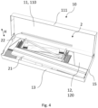
- Fig. 4 shows another collection of roof window product related components 2, where the second component 22, in the form a gutter-element, is attached to the internal top surface 110.
- the view shown in Fig. 4 corresponds largely to the display which the installer meets when opening the box, with a majority of the components supported on the bottom surface. The installer is thus afforded a good view of both the internal bottom and top surface 120, 110, and attaching components to the internal top surface maximizes the area of the box which can be used for logical arrangement of the components, i.e., in order of use. This advantage is more pronounced if more than one component is attached to the internal top surface 110.
- Figs. 5 and 6 show cross-sectional views of two boxes 10 which are in the process of being closed to provide the supply condition of the box/packed roof window product.
- the cross-sectional view corresponds to line I shown in Fig. 1 .
- the box is a five-panel fold type where the top side 11 is hinged to side wall 14, whereas in Fig. 6 the box is telescopic as the top side 11 and bottom side 12 are provided as separate pieces, the bottom side piece having side walls 13, 14, 15 which overlap with the overlap panels 111, 112 of the top side piece in the closed state of the box.
- the side walls of the telescopic box are configured to overlap fully, but telescopic boxes with partial overlap may also be used.
- Fig. 5 the box is a five-panel fold type where the top side 11 is hinged to side wall 14
- Fig. 6 the box is telescopic as the top side 11 and bottom side 12 are provided as separate pieces, the bottom side piece having side walls 13, 14, 15 which overlap with the overlap panels 111,
- each box contains a number of components 21, 23, 24, shown schematically, supported by the internal bottom surface 120, each of which can be considered the first component according to the invention.
- One of the components 24 determine the minimum height of the box 10, leaving room above some of the other components.
- An intermediate space 101 extends above component 21 seen along the height axis H. In the closed state of the box, and thus in the supply condition, the intermediate space 101 is delimited by component 21 and by the internal top surface 110.
- a further component, in the form of gutter element 22 is attached to the internal side surface 130, and extends in another intermediate space 101' above component 23.
- Gutter element 22 in Fig. 5 also engages component 23, which may contribute to keeping component 23 in place in the box, but still allowing component 23 and 22 to be retrieved separately from the box when unpacking.
- Cover element 22' on the other hand does not engage other components and is freely suspended from the internal top surface 110.
- FIG. 1 An embodiment of the method for packing a roof window product according to the invention is illustrated by Figs. 1 , 3 , 4 and 5 , even though they do not show the same roof window products.
- the box 10 is provided and arranged in a packing condition
- the first component e.g. in the form of stabilizing rails 21
- the second component in the form of gutter element 22
- the box 10 is in the process of being closed to provide the supply condition and thereby the packed roof window product.
- a figure showing the packed roof window product is not provided, but would show a closed box 10.
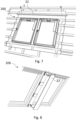
- FIGs. 7 and 8 show a gutter element 22 and a cover plate 22' being installed with a pair of roof windows 200.
Landscapes
- Engineering & Computer Science (AREA)
- Mechanical Engineering (AREA)
- Civil Engineering (AREA)
- Structural Engineering (AREA)
- Cartons (AREA)
Abstract
Description
- The present invention relates to a packed roof window product comprising a plurality of differently sized roof window related components accommodated in a box, wherein the box has a bottom side and a top side, which are spaced apart along a height axis, and side walls, which extend between the bottom side and top side of the box along the height axis, and where the bottom side, top side and side walls delimit an internal space of the box, which internal space accommodates the components, where the bottom side has an internal bottom surface, the top side has an internal top surface, and each side wall has an internal side surface, which internal bottom, top and side surfaces each face the internal space of the box, and where a first of said components is supported by the internal bottom surface.
- When installing a window in a roof it is vital to ensure that the roof window itself is securely attached to the roof structure and that the joint between the roof window and the roof structure is properly weather proofed. It is therefore important that all components of roof window products, such as the roof window itself or a flashing assembly for a roof window, are used and are used in the right way. To facilitate this, the components are typically arranged in the box in an intended order of use and small components, such as screws, are kept in plastic bags. Furthermore, packaging material components, such as blocks of expanded polystyrene or similar shock absorbing material are used for protecting the product and/or for keeping the components in the intended position within the box. An example of a packed roof window, where these principles are used, is known from
EP2748071B1 , and an example of a packed flashing assembly for a roof window is known fromEP1710163B1 . Traditionally small components have been attached to the box or to larger components, for example by means of an adhesive, to prevent them from becoming lost, either inside the box or when removed from the box, and/or they have been wrapped in plastic, thereby also preventing them from scratching or otherwise damaging other components. Larger components have traditionally been kept in place in the box by being attached to the box by means of an adhesive or by being fixated between blocks of expanded polystyrene (EPS), the blocks either filling out the space between the bottom and top sides and side walls or being attached thereto by an adhesive, and some have been covered by a protective plastic film to prevent them from being scratched. - However, with an ever-increasing awareness of environmental considerations and the wish to reduce or even eliminate the climate footprint of products and their packaging, there is a need for delivering packed roof window products that are more environmentally friendly.
- With this background, it is an object of the invention to provide a packed roof window product, which has a smaller climate footprint and/or with improved recyclability, without increasing the risk of errors in the installation of the product and maintaining a good protection of the components of the product during handling and transportation.
- These and further objects are achieved with a packed roof window product of the kind mentioned in the introduction, which is furthermore characterised in that a second of said components is attached to an internal surface of the box, which internal surface is selected from the internal top surface and the internal side surfaces.
- Packed roof window related components will include differently sized components or collections of components, and one or more of these will determine the minimum dimensions of the box, for example a minimum height. Other components do not extend the full height of the box and there will be left-over space in the box. In some cases, it may be possible to attach a one component to another component to make use of the left-over space, but this may require the provision of further packaging material in between them to protect the components or to provide a surface for adhesive in case direct adhesion to the components is unacceptable. Attaching components to each other may also have the disadvantage of grouping unrelated components, which are not used in the same installation step, making the unpacking and installation process more tedious for the installer and increases the risk of installation errors.
- By attaching the second component to an internal side surface or to the internal top surface, the second component can be elevated above the internal bottom surface and the internal space of the box can thereby be utilized more efficiently, potentially allowing for reducing the dimension of the box, and thereby provide a smaller climate footprint. At the same time, upon opening the box, the second component is clearly visible and easily accessible to the installer. The clearly visible and easily accessible position of the second component can advantageously be used for components to be used first or early in the installation of the roof window product. With the second component attached to the internal top surface or internal side surface the second component will be separate from other components, potentially eliminating or reducing the need for packaging material. This in turn may improve recyclability as there are fewer components to be collected for recycling, increasing the likelihood that the packaging material will be recycled. Attaching the second component prevents it from moving around in the box during transport, reducing the risk of it damaging other components, and thereby reducing waste as fewer products must be discarded and replaced with new products. A further advantage of attaching components to the internal top or side surfaces is an increase in the surface area of the box which can be used to arrange components in a logical manner, e.g. following the order of an installation process. Hence, the invention may provide reduced climate footprint and allow for a ordered placement of components in the box, contributing to reducing the risk of errors during the installation process. A further advantage of the invention is increased flexibility during the packing process, which will be described in greater detail below.
- The packed roof window is generally described herein with reference to the bottom side, top side and side walls of the box. The top and bottom side will typically constitute the major sides of the box, having a comparatively larger surface area than the side wall, which are then the minor sides of the box. The terminology refers to the intended orientation of the box in relation to gravity during packing or when opening the box, i.e. the bottom side below the top side in relation to gravity such that the height axis is parallel with gravity. The top side is the side, which is considered the lid of the box, i.e. the portion of the box which is moved when closing or opening box. The term roof window product as used herein may refer to a roof window or to an auxiliary product associated with a roof window, such as a flashing assembly or an insulation assembly. The term packed roof window product refers to a supply condition of the box, with the components accommodated, i.e. contained, in the closed box, i.e. the condition in which it is supplied to the installer. By components being accommodated in the box is understood that they are contained therein. The packaging in which the roof window product is packed, i.e. the box and possible additional packaging material components, such as spacers, inserts, wrappings etc., is single-use packaging, meaning that once the roof window product is unpacked, it is not replaced in the box, but collected for recycling, preferably. The term packing condition refers to a state of the box where it is open, possibly in an unfolded, partly folded or folded state, before and while components are packed into the box. The first component is supported by the internal bottom surface in the sense that it rests thereon and/or is retained in relation thereto. The second component may be attached to and in contact with the internal surface of the box. Alternatively, the second component may be arranged in a sub-packaging, such as paper bag, paper wrap, cardboard retainer or cardboard box, which sub-packaging is attached to and in contact with the internal surface of the box. The term sub-packaging refers to a packaging material component used to pack one or more of the window related components, and which sub-packaging is packed in the box accommodating the roof window related product.
- In an embodiment, the second component is attached to the internal top surface. Attaching the second component to the internal top surface may be particularly advantageous during the packing process as the bottom side and top side, may be accessible from different positions alongside a production assembly line. This allows one operator, which may be human or robot, to pack components onto the bottom side while a second operator attaches the second component to the top side, the operators either reaching out in different lengths from their positions side by side or reaching out from their positions on different sides of the assembly line. By comparison, the side walls are typically attached to the bottom side, and thus less accessible for the second operator. For example, in a five-panel fold type box, wherein the top side is hinged to a sidewall, both top side and bottom side may face upwards in the packing condition of the box, allowing two operators to pack simultaneously from either side of the box on an assembly line. Accordingly, the number of packing operations per unit length of assembly line can be increased, potentially reducing the length of the assembly line. Attaching components to the internal top surface also weighs down the top side of the box, which may be useful for some box types serving to keep it in an open state after the installer has opened the box.
- Attaching components to the internal top surface may reduce the number of components supported on the internal bottom surface. This may allow for the plurality of components to be laid out in convenient manner, where the installer has a good view of the individual components on the internal top and bottom surfaces upon opening the box. In some embodiments, the internal surfaces of the box may be provided with information, e.g. printed thereon, concerning the components. In an embodiment, the information is the order of installation, which could be indicated by printed numbers adjacent to the components. This possibility may arise due to better utilization of the available surface area for component distribution and fewer components on top of each other.
- In an embodiment, the second component is attached by an adhesive. Using an adhesive, such as a glue or tape, is advantageous in terms of recyclability or reprocessing as a relatively minor amount of adhesive is required compared to the material forming the box. For example, box is preferably made from a cardboard material and reprocessing value cardboard is dependent on the amount of non-paper material, hence minor amounts of glue will typically not or only to a small amount reduce reprocessing value. The adhesive may also be a paper-tape (having adhesive on at least one side), which is sorted as the same waste fraction as the cardboard box. Similarly, a double-sided adhesive paper tape can also be used.
- In some embodiments, a cardboard retainer is attached to the internal top surface or internal side surface and the second component is retained by the cardboard retainer. Such a cardboard retainer may be attached by an adhesive in the manner described in the preceding paragraph.
- Using an adhesive to attach the second component provides a means of attachment which uses a small amount of non-paper material which is not, or only to a small degree, detrimental to reprocessing value. Some types of second components may however be attached to the internal surface using a structure formed in the internal surface, which structure retains the second component. Said structure may be a slit, slot or flap formed from the top side or side wall comprising the internal surface to which the second component is attached. One or more flaps may for example protrude into the second component, thereby supporting the second component and thus attaching it to the internal surface. One or more slits or slots may allow a part of the second component to extend through the internal surface which thereby supports the second component and attaches it to the internal surface. In one exemplary embodiment, the second component is a gutter-shaped component which is retained by flaps formed in the internal surface. Gutter shaped components are described in greater detail below.
- Other means of attaching the second component to the internal surface are possible, such as hook-and-loop fasteners, which may provide the advantages of the invention associated with the position of the second component, but which may not less advantageous in terms of climate foot-print and recyclability than the aforementioned adhesives or structures used for attaching the second component.
- In an embodiment, an intermediate space extends along the height axis between the internal top surface and the first component and at least part of the second component is positioned in the intermediate space. The intermediate space is left-over space which arises due to the different sizes of the components, and the intermediate space is utilized by having the second component attached to one of the internal side surfaces or the internal top surface. The entirety of the second component may extend in such an intermediate space.
- In an embodiment, the first component is retained in relation to the internal bottom surface, preferably by being attached thereto, such as by an adhesive. When a component is retained in relation to something, the component is kept in place, preventing it from moving in relation thereto. By attaching the first component the risk of it damaging other components or itself being damaged is reduced.
- In an embodiment, the second component engages another component of the plurality of components or a packaging material component, which component or packaging material component is supported by the internal bottom surface. The packaging material component is a piece of packaging included in the box for packing purposes, which is not a roof window related component, such as spacers, blocks of shock absorbing material or retainers/inserts for keeping roof window related components in place. Such packaging materials are preferably made from a paper material, such as cardboard or moulded paper pulp. By having the second component engage another component or packaging material component, the latter can be kept in place, preventing it from moving around in the box. This may reduce the need for e.g., adhesives to keep such other components or packaging material components in place. In an embodiment, the second component is a gutter-shaped component of a covering assembly or a flashing assembly for a roof window. Gutter-shaped components are typically used to drain off water, for example along the top of a roof window installed in an inclined roof, where a gutter element drains water out onto one or more side flashing members extending along the side(s) of the roof window. Another gutter-shaped component, which may suitably be attached to the internal top or side surfaces, is a cover member of a covering assembly. The gutter-element and cover element are also examples of components which are relatively long and stiff, which can may also serve to strengthen and/or brace the box. Still further examples of components which may serve as the second component, are insulating frame members, stabilizing rails, underroof collars, vapour barriers, instruction manuals, and paper bags or cardboard boxes containing small components, such as fasteners or brackets for use during the installation process.
- In an embodiment, the box is made from a paper-based material, preferably cardboard, more preferably corrugated cardboard. These materials are readily recyclable.
- In an embodiment, the box is a five-panel fold type box or a telescopic type box. A five-panel fold type box (sometimes referred to as five-panel-folder) is a standard box type, where the top side is hinged to one of the side walls and additional panels are provided to overlap with the side walls in the closed state of the box. Telescopic boxes are also a standard box type, wherein the box comprises two separate pieces, a top side piece and bottom side piece, which can be fitted to each other such that side walls of one piece is overlapped at least partly by the side walls of the other piece. Both of these box types allow for the bottom and top side to be packed simultaneously as they are separately accessible in the packing condition.
- The respective sides of the box, i.e. top side, bottom side and side walls, may in some embodiments comprise a plurality of panels arranged to make up the respective side. This will typically be the case for one or more of the sides in a folded cardboard box, where two or more panels overlap in the folded state. In such embodiments, the respective internal surfaces are considered to be the sum of the surfaces of the panels making up a side, which surfaces delimit the internal space of the box and are exposed toward the internal space of box in the closed state.
- In an embodiment, a majority of the plurality of components are supported by the internal bottom surface. Said majority may be retained in relation to the bottom side. The bottom side is thus the primary surface on which the components are packed and attaching the second component serves to utilize left-over space in the box. In other words, at least 50 %, at least 60 %, at least 70 %, at least 80 % or at least 90 % by area of the internal bottom surface is occupied by components supported thereon.
- In an embodiment, the second component does not contact the internal bottom surface. Having the second component freely suspended in this way, may reduce the need for e.g. protective wrappings as the second component will not scratch other components.
- In an embodiment, an internal box height extends between the internal top surface and internal bottom surface of the box, which internal box height substantially corresponds to the height of at least one of the components accommodated in the box.
- In an embodiment, further components of the plurality of components are attached to internal top surface and/or to the internal side surface, respectively.
- In a further aspect of the invention, there is provided a method for packing a roof window product into a box, which roof window product comprises a plurality of differently sized roof window related components, wherein the method comprises the steps of:
- providing a box having a bottom side, a top side and side walls, the box having a supply condition in which the bottom side and top side are spaced apart along a height axis, the side walls of the box extend between the bottom side and top side of the box along the height axis, the bottom side, top side and side walls delimit an internal space of the box, which internal space accommodates the components, and the bottom side has an internal bottom surface, the top side has an internal top surface, and each side wall has an internal side surface, which internal bottom, top and side surfaces each face the internal space of the box,
- arranging the box in a packing condition in which the box is open,
- positioning a first of said components on the internal bottom surface,
- attaching a second of said components to an internal surface of the box, which internal surface is selected from the internal top surface and the internal side surfaces,
- closing the box to provide the supply condition of the box and thereby a packed roof window product.
- For a cardboard box, the open state of the box includes the unfolded state, a partly folded state and the folded state.
- Attaching the second component to the internal surface in a unfolded state of the box may be advantageous. In the unfolded state, the top side or side wall to which the second is to be attached is horizontal and hence when the second component is attached using an adhesive, there is no need to support the second component while the adhesive cures/dries. In the unfolded-state the top side and side walls may also be more accessible for the operator (human or robot) packing the roof window product, facilitating the packing operation.
- The first component may be positioned on the internal bottom surface prior to or after attaching the second component to the internal surface. The box may be folded in between positioning and attaching the first component and second components respectively. For example, the second component may be attached to the internal surface in an unfolded state of the box, whereafter the box is folded to provide a folded or partly folded, but still open, state of the box, whereafter the first component is positioned on the internal bottom surface, whereafter the box is closed.
- In some embodiments of the method the second component is attached to the internal top surface.
- In some embodiments of the method, the first component is retained in relation to the internal bottom surface after the step of positioning the first component.
- In some embodiments, the internal top surface and the internal bottom surface face in substantially the same direction in the packing condition.
- The method may comprise additional features corresponding to the embodiments of the packed roof window product described above, as will be readily apparent to the skilled practitioner. For example, the method may comprise applying an adhesive to the second component and/or to the internal top or side surface to attach the second component by means of the adhesive. The method may also or alternatively, involve a step of positioning the second component on the internal top or an internal side surface, such that it will extend at least partly in the intermediate space above the first component, or such that it engages another component of the plurality of components or a packaging material component. Similarly, the box provided in the method may be a cardboard box and the components may be the specific components previously described.
- Other embodiments and further advantages will be apparent from the subsequent detailed description and drawings.
- In the following, embodiments of the invention will be described with reference to the schematic drawings in which
-
Fig. 1 is a perspective view of a box in a packing condition with an open top side, -
Fig. 2 shows a box in an unfolded packing condition, -
Fig. 3 and4 show boxes in the process of being packed, -
Fig. 5 and 6 are cross-sectional views of two different box types in the process of being closed, and -
Fig. 7 and 8 shows the installation of a gutter element and a cover plate, respectively, at a pair of roof windows. - Referring initially to
Fig. 1 which shows a perspective view from above of abox 10 of the five-panel fold type in a folded and open state. The box is also in a packing condition where it is ready for roof window related components (not shown) to be packed therein. Thebox 10 has atop side 11 forming the lid of thebox 10 and abottom side 12, which top and bottom side are the major sides of thebox 10. The box hasside walls bottom side 12 and the free edges of the side walls 13-16 engage the top side when thebox 10 is closed and when the packed roof window product is in its supply condition. Thetop side 11 is provided withoverlap panels side walls Fig. 1 ), 140, 150, 160 along with aninternal bottom surface 120 and an internaltop surface 110 delimit aninternal space 100 of the box, in the supply condition. In an alternative embodiment, what is denoted theoverlap panels Fig. 1 could be adapted to overlap on the internal side of what is denotedside walls Fig. 1 , in which case theoverlap panels side wall 14 would delimit theinternal space 100 in the supply condition, and thus be "side walls" of the box in the context of the invention. Returning to the embodiment shown inFig. 1 , thebox 10 is folded, and thusside wall 16, is formed by three panels: One which is attached to thebottom side 12 and two comparatively smaller panels which are attached toside wall internal surface 160 ofside wall 16 is made up of the internally facing and exposed surfaces of the three panels. In comparison,side walls -
Fig. 2 shows abox 10 similar to the one inFig. 1 but in an unfolded state, which may also be referred to as a blank. Thebox 10 is made from cardboard which has cuts or weakened portions allowing it to be folded. As can be seen, the panels forming theside wall 13,bottom side 12,side wall 14,top side 11 andoverlap panel 111 are arranged sequentially with weakened lines for folding in between (shown as dash-dot lines), giving rise to the "five-panel fold" name. A number of glue strips 123, 113, 115 provided. Theglue strip 115 on theoverlap panel 111 is for attachment to the external surface of side wall 13 (not shown) in the closed state of the box. Glue strips 123 on the internalbottom surface 120 is provided for attaching a roof window product related component (not shown) to the box. Similarly,glue strip 113 on the internaltop surface 110 is for attaching another roof window product related component (not shown) to the internaltop surface 110. In this case, the component to be attached to the internaltop surface 110 is a relative long component. Additionally or alternatively, a glue strip (not shown) could be provided on theinternal side surface box 10 ofFig. 2 is further provided with a pull-and-tear strip 114 for opening the box, here embodied as a weakened portion of thetop side 11. The unfolded state of the box shown inFig. 2 can also be used as the packing condition, as components may be arranged on the internal surfaces of the box. - Referring now to
Figs. 3 and4 which show different collections of roof window product relatedcomponents 2 being packed in a foldedbox 10. Thebox 10 is in the packing condition and inFig. 3 the internaltop surface 110 and internalbottom surface 120 face substantially in the same direction, i.e. upwards in relation the height axis. The packing process is typically performed on a packing line where the box moves on a conveyor belt. The direction of movement is typically longitudinal, i.e. the direction perpendicular to the height direction and in whichside wall 13 extends. Traditionally packing operators are positioned atside wall 13 to arrange components on thebottom side 12 of the box. However, by attaching some of the components to the internaltop surface 110, another second operator can be positioned at the side of theoverlap panel 111, which may along with thetop side 11 be moved to extend substantially horizontally i.e. parallel with thebottom side 12, which second operator can then attach components to the internal top surface. Thus the number of packing operations per unit length of packing line is increased thereby potentially reducing the length of the packing line. Thebottom side 12 is not accessible to said second operator due to the size of boxes for roof window products, hence having said second operator at theoverlap panel 111 is made possible by a method of packing comprising attaching second components to the internaltop surface 110. - In
Fig. 3 the roof window product is a number of installation assemblies used when installing a roof window, and it comprises a plurality of components with different sizes arranged on the internalbottom surface 120. One component is aninsulation frame assembly 24 the length and height of which is seen to almost extend the full length and height of the box. By comparison anothercomponent 21, here a pair of stabilizing rails which are retained in packaging material components in the form ofcardboard retainers 210, are shorter in height, leaving anintermediate space 101 above them. All of thecomponents 2 shown inFig. 3 are supported by the internal bottom surface and may be considered as the first component in the context of the invention. The stabilizing rails 21 are also attached to the internalbottom surface 120 by adhesive on theretainers 210.Glue strip 113 is provided on the internaltop surface 110 allowing a second component (not shown) to be attached to the internaltop surface 110. Theglue strip 113 is positioned such that the second component (not shown) will extend at least partly in theintermediate space 101 above the stabilizing rails 21. Theglue strip 113 is here adapted for attaching a gutter element (seeFig. 7 ), which is a metal component which should be kept in place to keep it from damaging other components. However, the gutter element is installed at later stage than the stabilizingrails 21, and simply attaching the gutter element to the stabilizingrails 21, would group unrelated components. Hence, the installer would have to take out the gutter element and set it aside, then retrieve the stabilizing rails and then at later stage take out the gutter element, which could be misplaced in the meantime, potentially making the unpacking and installation less efficient. By attaching the gutter element to the top internaltop surface 110, it is kept in place separately allowing the installer to take it out separately at the appropriate time, potentially making the installation more efficient. - Turning to
Fig. 4 which shows another collection of roof window product relatedcomponents 2, where thesecond component 22, in the form a gutter-element, is attached to the internaltop surface 110. While thebox 10 is here in the process of being packed, the view shown inFig. 4 corresponds largely to the display which the installer meets when opening the box, with a majority of the components supported on the bottom surface. The installer is thus afforded a good view of both the internal bottom andtop surface top surface 110. - Referring now to
Figs. 5 and 6 which show cross-sectional views of twoboxes 10 which are in the process of being closed to provide the supply condition of the box/packed roof window product. The cross-sectional view corresponds to line I shown inFig. 1 . InFig. 5 the box is a five-panel fold type where thetop side 11 is hinged toside wall 14, whereas inFig. 6 the box is telescopic as thetop side 11 andbottom side 12 are provided as separate pieces, the bottom side piece havingside walls overlap panels Fig. 5 and 6 theside walls bottom side 12 and delimit theinternal space 100 of the box. Each box contains a number ofcomponents bottom surface 120, each of which can be considered the first component according to the invention. One of thecomponents 24 determine the minimum height of thebox 10, leaving room above some of the other components. Anintermediate space 101 extends abovecomponent 21 seen along the height axis H. In the closed state of the box, and thus in the supply condition, theintermediate space 101 is delimited bycomponent 21 and by the internaltop surface 110. InFigs. 5 and 6 a second component in the form of cover element 22' andgutter element 22, respectively, extends at least partly in theintermediate space 101. InFig. 5 a further component, in the form ofgutter element 22 is attached to theinternal side surface 130, and extends in another intermediate space 101' abovecomponent 23.Gutter element 22 inFig. 5 also engagescomponent 23, which may contribute to keepingcomponent 23 in place in the box, but still allowingcomponent top surface 110. - An embodiment of the method for packing a roof window product according to the invention is illustrated by
Figs. 1 ,3 ,4 and5 , even though they do not show the same roof window products. InFig. 1 thebox 10 is provided and arranged in a packing condition, inFig. 3 the first component, e.g. in the form of stabilizingrails 21, is arranged on the internalbottom surface 120, inFig. 4 the second component, in the form ofgutter element 22 is attached to the internaltop surface 110, and inFig. 5 thebox 10 is in the process of being closed to provide the supply condition and thereby the packed roof window product. A figure showing the packed roof window product is not provided, but would show aclosed box 10. - Referring now to
Figs. 7 and 8 which show agutter element 22 and a cover plate 22' being installed with a pair ofroof windows 200. -
- 2
- Window product related components
- 21
- First component
- 22, 22'
- Second component
- 23, 24
- Other component
- 10
- Box, Cardboard box
- 100
- Internal space
- 101, 101'
- Intermediate space
- 11
- Top side
- 110
- Internal top surface
- 111
- Overlap panel
- 112
- Overlap panel
- 113
- Adhesive
- 114
- Pull-and-tear strip
- 115
- Adhesive
- 12
- Bottom side
- 120
- Internal bottom surface
- 123
- Adhesive
- 13
- Side wall
- 130
- Internal side surface
- 14
- Side wall
- 140
- Internal side surface
- 15
- Side wall
- 150
- Internal side surface
- 16
- Side wall
- 160
- Internal side surface
- 200
- Pair of roof windows
- H
- Height axis
Claims (14)
- A packed roof window product comprising a plurality of differently sized roof window related components (2) accommodated in a box (10), whereinthe box has a bottom side (12) and a top side (11), which are spaced apart along a height axis (H), and side walls (13, 14, 15, 16), which extend between the bottom side and top side of the box along the height axis, and where the bottom side, top side and side walls delimit an internal space (100) of the box, which internal space accommodates the components (2),the bottom side has an internal bottom surface (120), the top side has an internal top surface (110), each side wall has an internal side surface (130, 140, 150, 160), which internal bottom, top and side surfaces each face the internal space of the box, anda first of said components (21) is supported by the internal bottom surface (120),characterised in thata second of said components (22) is attached an internal surface of the box, which internal surface is selected from the internal top surface (110) and the internal side surfaces (130, 140, 150, 160).
- A packed roof window product according to claim 1, wherein the second component (22) is attached to the internal top surface (110).
- A packed roof window product according to claim 1 or 2, wherein the second component is attached by an adhesive (113).
- A packed roof window product according to any one of the preceding claims, wherein an intermediate space (101) extends along the height axis between the internal top surface (110) and the first component (21) and wherein at least part of the second component (22) is positioned in the intermediate space (101).
- A packed roof window product according to any one of the preceding claims, wherein the first component (21) is retained in relation to the internal bottom surface (120), preferably by being attached thereto, such as by an adhesive (123).
- A packed roof window product according to any one of the preceding claims, wherein the second component (22) engages another component of the plurality of components or a packaging material component, which component or packaging material component is supported by the internal bottom surface (120).
- A packed roof window product according to any one of the preceding claims, wherein the second component (22) is a gutter-shaped component of a covering assembly or a flashing assembly for a roof window, such as a cover plate or gutter element respectively.
- A packed roof window product according to any one of the preceding claims, wherein the box (10) is made from a paper-based material, preferably cardboard, more preferably corrugated cardboard.
- A packed roof window product according to any one of the preceding claims, wherein the box is a five-panel fold type box or a telescopic type box.
- A packed roof window product according to any one of the preceding claims, wherein a majority of the plurality of components (2) are supported by the internal bottom surface (120).
- A packed roof window product according to any one of the preceding claims, wherein the second component (22) does not contact the internal bottom surface (120).
- A method for packing a roof window product into a box (10), which roof window product comprises a plurality of differently sized roof window related components (2), wherein the method comprises the steps of:- providing a box (10) having a bottom side (12), a top side (13), and side walls (13, 14, 15, 16), the box having a supply condition in which the bottom side and top side are spaced apart along a height axis (H), the side walls of the box extend between the bottom side and top side of the box along the height axis, the bottom side, top side and side walls delimit an internal space (100) of the box, which internal space accommodates the components, and the bottom side has an internal bottom surface (120), the top side has an internal top surface (110), and each side wall has an internal side surface (130, 140, 150, 160), which internal bottom, top and side surfaces each face the internal space of the box,- arranging the box in a packing condition in which the box (10) is open, optionally in an unfolded state of the box,- positioning a first of said components (21) on the internal bottom surface (120),- attaching a second of said components (22) to an internal surface of the box, which internal surface is selected from the internal top surface (110) and the internal side surfaces (130, 140, 150, 160),- closing the box to provide the supply condition of the box and thereby a packed roof window product.
- A method for packing a roof window product according to claim 11, wherein the second component (22) is attached to the internal top surface (110).
- A method for packing a roof window product according to claim 12 or 13, wherein, after the step of positioning the first component (21), the first component is retained in relation to the internal bottom surface (120).
AWA Denmark A/S
Applications Claiming Priority (1)
| Application Number | Priority Date | Filing Date | Title |
|---|---|---|---|
| DKPA202270411A DK181716B1 (en) | 2022-08-19 | 2022-08-19 | A packed roof window product and a method for packing a roof window product |
Publications (1)
| Publication Number | Publication Date |
|---|---|
| EP4324758A1 true EP4324758A1 (en) | 2024-02-21 |
Family
ID=87760243
Family Applications (1)
| Application Number | Title | Priority Date | Filing Date |
|---|---|---|---|
| EP23192098.4A Pending EP4324758A1 (en) | 2022-08-19 | 2023-08-18 | A packed roof window product and a method for packing a roof window product |
Country Status (2)
| Country | Link |
|---|---|
| EP (1) | EP4324758A1 (en) |
| DK (1) | DK181716B1 (en) |
Cited By (1)
| Publication number | Priority date | Publication date | Assignee | Title |
|---|---|---|---|---|
| DK182276B1 (en) * | 2024-07-31 | 2026-02-03 | Vkr Holding As | A packaging for components of a roof window product |
Citations (6)
| Publication number | Priority date | Publication date | Assignee | Title |
|---|---|---|---|---|
| GB454281A (en) * | 1935-04-24 | 1936-09-28 | Hugo Kenneth Paffard | Improvements in and relating to display boxes |
| US5240109A (en) * | 1991-04-26 | 1993-08-31 | Highland Supply Corporation | Shipping carton for floral grouping assemblies |
| JP2002173178A (en) * | 2000-12-01 | 2002-06-18 | Tostem Corp | Package for water-dripping member for skylight window |
| US6575299B1 (en) * | 2000-09-06 | 2003-06-10 | Kraft Foods Holdings, Inc. | Meal kit packaging system |
| EP1710163A1 (en) * | 2005-04-08 | 2006-10-11 | VKR Holding A/S | Process, package and protecting elements for the packaging of a product having multiple components |
| EP2748071B1 (en) | 2011-10-04 | 2016-11-23 | VKR Holding A/S | A packaging for a window and a method for packing |
Family Cites Families (1)
| Publication number | Priority date | Publication date | Assignee | Title |
|---|---|---|---|---|
| DK202070161A1 (en) * | 2020-03-10 | 2021-10-29 | Vkr Holding As | A packaging for installation elements for a roof window, a packed kit of installation elements, and method of providing a packaging for roof window installation elements |
-
2022
- 2022-08-19 DK DKPA202270411A patent/DK181716B1/en active IP Right Grant
-
2023
- 2023-08-18 EP EP23192098.4A patent/EP4324758A1/en active Pending
Patent Citations (7)
| Publication number | Priority date | Publication date | Assignee | Title |
|---|---|---|---|---|
| GB454281A (en) * | 1935-04-24 | 1936-09-28 | Hugo Kenneth Paffard | Improvements in and relating to display boxes |
| US5240109A (en) * | 1991-04-26 | 1993-08-31 | Highland Supply Corporation | Shipping carton for floral grouping assemblies |
| US6575299B1 (en) * | 2000-09-06 | 2003-06-10 | Kraft Foods Holdings, Inc. | Meal kit packaging system |
| JP2002173178A (en) * | 2000-12-01 | 2002-06-18 | Tostem Corp | Package for water-dripping member for skylight window |
| EP1710163A1 (en) * | 2005-04-08 | 2006-10-11 | VKR Holding A/S | Process, package and protecting elements for the packaging of a product having multiple components |
| EP1710163B1 (en) | 2005-04-08 | 2009-06-03 | VKR Holding A/S | Process, package and protecting elements for the packaging of a product having multiple components |
| EP2748071B1 (en) | 2011-10-04 | 2016-11-23 | VKR Holding A/S | A packaging for a window and a method for packing |
Cited By (3)
| Publication number | Priority date | Publication date | Assignee | Title |
|---|---|---|---|---|
| DK182276B1 (en) * | 2024-07-31 | 2026-02-03 | Vkr Holding As | A packaging for components of a roof window product |
| DK202470204A1 (en) * | 2024-07-31 | 2026-02-03 | Vkr Holding As | A packaging for components of a roof window product |
| EP4686663A1 (en) * | 2024-07-31 | 2026-02-04 | VKR Holding A/S | A packaging for components of a roof window product |
Also Published As
| Publication number | Publication date |
|---|---|
| DK181716B1 (en) | 2024-10-31 |
| DK202270411A1 (en) | 2024-02-20 |
Similar Documents
| Publication | Publication Date | Title |
|---|---|---|
| US3669337A (en) | Packaging sleeve with heat-shrinkable protection sling and blank for producing same | |
| CN109641676B (en) | Display case with retaining device | |
| DK181304B1 (en) | A packed roof window | |
| US12428193B2 (en) | Packed roof window products | |
| US20140238879A1 (en) | Packaging for a window and a method for packing | |
| CN115243979A (en) | Package for dormer window mounting element and method of providing such package | |
| DK181716B1 (en) | A packed roof window product and a method for packing a roof window product | |
| EP4412922B1 (en) | Packed roof window product, a method for packing a packed roof window product, and a method of unpacking a packed roof window product | |
| EP4091959B1 (en) | A packed roof window comprising a ventilation flap retainer | |
| EP4412913B1 (en) | Packed roof window product | |
| US5871101A (en) | Reusable slotted suspension bulk package | |
| EP4089022A2 (en) | Packed roof window product | |
| EP4089026B1 (en) | Packed roof window products | |
| EP1292515B1 (en) | Package for rod-shaped articles along with accessories comprising inspection windows | |
| EP4089024A2 (en) | Packed roof window products and a method for installation of a roof window product | |
| DK182276B1 (en) | A packaging for components of a roof window product | |
| CN2841520Y (en) | Packing box | |
| WO1993014004A1 (en) | Improved packaging element |
Legal Events
| Date | Code | Title | Description |
|---|---|---|---|
| PUAI | Public reference made under article 153(3) epc to a published international application that has entered the european phase |
Free format text: ORIGINAL CODE: 0009012 |
|
| STAA | Information on the status of an ep patent application or granted ep patent |
Free format text: STATUS: THE APPLICATION HAS BEEN PUBLISHED |
|
| AK | Designated contracting states |
Kind code of ref document: A1 Designated state(s): AL AT BE BG CH CY CZ DE DK EE ES FI FR GB GR HR HU IE IS IT LI LT LU LV MC ME MK MT NL NO PL PT RO RS SE SI SK SM TR |
|
| STAA | Information on the status of an ep patent application or granted ep patent |
Free format text: STATUS: REQUEST FOR EXAMINATION WAS MADE |
|
| 17P | Request for examination filed |
Effective date: 20240819 |
|
| RBV | Designated contracting states (corrected) |
Designated state(s): AL AT BE BG CH CY CZ DE DK EE ES FI FR GB GR HR HU IE IS IT LI LT LU LV MC ME MK MT NL NO PL PT RO RS SE SI SK SM TR |
|
| STAA | Information on the status of an ep patent application or granted ep patent |
Free format text: STATUS: EXAMINATION IS IN PROGRESS |
|
| 17Q | First examination report despatched |
Effective date: 20251017 |