EP4324583A2 - Compact multi-material cut-off tool - Google Patents
Compact multi-material cut-off tool Download PDFInfo
- Publication number
- EP4324583A2 EP4324583A2 EP24150632.8A EP24150632A EP4324583A2 EP 4324583 A2 EP4324583 A2 EP 4324583A2 EP 24150632 A EP24150632 A EP 24150632A EP 4324583 A2 EP4324583 A2 EP 4324583A2
- Authority
- EP
- European Patent Office
- Prior art keywords
- tool
- cut
- blade guard
- arbor
- housing
- Prior art date
- Legal status (The legal status is an assumption and is not a legal conclusion. Google has not performed a legal analysis and makes no representation as to the accuracy of the status listed.)
- Pending
Links
- 239000000463 material Substances 0.000 title description 5
- 238000005520 cutting process Methods 0.000 claims abstract description 65
- 230000002401 inhibitory effect Effects 0.000 claims description 3
- 239000012780 transparent material Substances 0.000 claims description 2
- 230000004913 activation Effects 0.000 description 3
- 210000003811 finger Anatomy 0.000 description 3
- 230000003213 activating effect Effects 0.000 description 1
- 239000003086 colorant Substances 0.000 description 1
- 230000006835 compression Effects 0.000 description 1
- 238000007906 compression Methods 0.000 description 1
- 238000010276 construction Methods 0.000 description 1
- 230000000881 depressing effect Effects 0.000 description 1
- 210000003813 thumb Anatomy 0.000 description 1
Images




Classifications
-
- B—PERFORMING OPERATIONS; TRANSPORTING
- B23—MACHINE TOOLS; METAL-WORKING NOT OTHERWISE PROVIDED FOR
- B23D—PLANING; SLOTTING; SHEARING; BROACHING; SAWING; FILING; SCRAPING; LIKE OPERATIONS FOR WORKING METAL BY REMOVING MATERIAL, NOT OTHERWISE PROVIDED FOR
- B23D47/00—Sawing machines or sawing devices working with circular saw blades, characterised only by constructional features of particular parts
- B23D47/12—Sawing machines or sawing devices working with circular saw blades, characterised only by constructional features of particular parts of drives for circular saw blades
-
- B—PERFORMING OPERATIONS; TRANSPORTING
- B25—HAND TOOLS; PORTABLE POWER-DRIVEN TOOLS; MANIPULATORS
- B25F—COMBINATION OR MULTI-PURPOSE TOOLS NOT OTHERWISE PROVIDED FOR; DETAILS OR COMPONENTS OF PORTABLE POWER-DRIVEN TOOLS NOT PARTICULARLY RELATED TO THE OPERATIONS PERFORMED AND NOT OTHERWISE PROVIDED FOR
- B25F5/00—Details or components of portable power-driven tools not particularly related to the operations performed and not otherwise provided for
-
- B—PERFORMING OPERATIONS; TRANSPORTING
- B27—WORKING OR PRESERVING WOOD OR SIMILAR MATERIAL; NAILING OR STAPLING MACHINES IN GENERAL
- B27B—SAWS FOR WOOD OR SIMILAR MATERIAL; COMPONENTS OR ACCESSORIES THEREFOR
- B27B9/00—Portable power-driven circular saws for manual operation
-
- B—PERFORMING OPERATIONS; TRANSPORTING
- B27—WORKING OR PRESERVING WOOD OR SIMILAR MATERIAL; NAILING OR STAPLING MACHINES IN GENERAL
- B27B—SAWS FOR WOOD OR SIMILAR MATERIAL; COMPONENTS OR ACCESSORIES THEREFOR
- B27B9/00—Portable power-driven circular saws for manual operation
- B27B9/02—Arrangements for adjusting the cutting depth or the amount of tilting
-
- B—PERFORMING OPERATIONS; TRANSPORTING
- B27—WORKING OR PRESERVING WOOD OR SIMILAR MATERIAL; NAILING OR STAPLING MACHINES IN GENERAL
- B27G—ACCESSORY MACHINES OR APPARATUS FOR WORKING WOOD OR SIMILAR MATERIALS; TOOLS FOR WORKING WOOD OR SIMILAR MATERIALS; SAFETY DEVICES FOR WOOD WORKING MACHINES OR TOOLS
- B27G19/00—Safety guards or devices specially adapted for wood saws; Auxiliary devices facilitating proper operation of wood saws
- B27G19/02—Safety guards or devices specially adapted for wood saws; Auxiliary devices facilitating proper operation of wood saws for circular saws
- B27G19/04—Safety guards or devices specially adapted for wood saws; Auxiliary devices facilitating proper operation of wood saws for circular saws for manually-operated power-driven circular saws
Definitions
- the present invention relates to power tools, and more specifically to cut-off tools.
- Cut-off tools such as multi-material cut-off tools, typically include a blade guard at least partially surrounding a cutting disk of the cut-off tool.
- the present invention provides, in one aspect, a compact multi-material cut-off tool.
- the present invention provides, in another aspect, a cut-off tool including a housing, an arbor supported by the housing for relative movement therewith, and a cutting disk attachable to the arbor.
- the cut-off tool further includes a motor coupled to the arbor to provide torque thereto, and a battery pack removably coupled to the housing.
- the battery pack is for providing power to the motor.
- the cut-off tool further includes a switch operable to adjust rotation of the motor between a first rotational direction and an opposite, second direction for selectively rotating the cutting disk in the first rotational direction or second rotational direction, respectively.
- the present invention provides, in another aspect, a cut-off tool a housing, an arbor supported by the housing for relative movement therewith, and a cutting disk attachable to the arbor.
- the cut-off tool further includes a blade guard surrounding an upper portion of the cutting disk, a retaining clip securing the blade guard to the housing, and a detent mechanism between the blade guard and the retaining clip.
- the detent mechanism is for selectively holding the blade guard in one of a plurality of positions relative to the housing.
- the present invention provides, in another aspect, a cut-off tool including a housing, an arbor supported by the housing for relative movement therewith, and a flange coupled for co-rotation with the arbor against which a cutting disk is clamped.
- the cut-off tool further includes an adapter ring coupled for co-rotation with the flange.
- An outer diameter of the adapter ring is nominally less than an inner diameter of an aperture in the cutting disk for aligning the cutting disk with the arbor.
- FIGS. 1-14 illustrate all or portions of a cut-off tool, such as a compact multi-material cut off tool 10.
- the cut-off tool 10 includes a housing 14, a motor 16 ( FIG. 3 ) positioned within a motor housing portion 18 of the housing 14, and an arbor 22 driven by the motor 16 to which a small diameter (e.g., 3 inch) cutting or grinding disk (hereinafter, "cutting disk 24") is attachable.
- the housing 14 also includes a handle portion 26 extending transversely from the motor housing portion 18 and terminating in a receptacle 30 in which a battery pack (not shown) is received.
- the cut-off tool 10 also includes a trigger 34 ( FIGS.
- the cut-off tool 10 further includes a forward/reverse selector shuttle 38 ( FIG. 6 ) located adjacent the front of the handle portion 26 and forward of the trigger 34, permitting the user to select either a forward or reverse rotational direction of the motor 16 with their thumb, for example, while maintaining their grasp on the handle portion 26 with their index finger on the trigger 34.
- the forward/reverse selector shuttle 38 includes an indicator portion 156 that is movable within the handle portion 26 of the housing 14, which includes a forward/reverse blade direction display window 172 ( FIGS. 1 and 3 ).
- the display window 172 is defined by first, second, and third slots 176A, 176B, 176C ( FIG. 1 ).
- the first and second slots 176A, 176B are located proximate laterally opposite sides of the handle portion 26, and the third slot 176C is between the first and second slots 176A, 176B.
- the indicator portion 156 of the forward/reverse selector shuttle 38 includes a surface 180 in facing relationship with the first, second, and third slots 176A, 176B, 176C ( FIGS. 13 and 14 ).
- the surface 180 includes first, second, and third sections 184A, 184B, 184C which include different colors (i.e., white) than the base color of the surface 180 (i.e., gray; FIG. 14 ).
- the first, second, and third sections 184A, 184B, 184C are spaced from each other on the surface 180.
- the third section 184C is between the first and second sections 184A, 184B.
- the display window 172 includes symbols to indicate to the user the rotational direction of the motor 16.
- the illustrated display window 172 includes the letter “F” positioned adjacent the first slot 176A, the letter “R” positioned adjacent the second slot 176B, and a padlock icon positioned adjacent the third slot 176C, and between the letter “F” and the letter “R” ( FIG. 1 ).
- the letter “F” corresponds to a forward direction of the motor 16
- the letter “R” corresponds to a reverse direction of the motor 16
- the padlock icon corresponds to a lockout position of the trigger 34 in which the motor 16 cannot be operated.
- movement of the forward/reverse selector shuttle 38 adjusts the color scheme of the display window 172 to indicate the direction of the motor 16. Specifically, movement of the forward/reverse selector shuttle 38 positions the first, second, and third sections 184A, 184B, 184C relative to the first, second, and third slots 176A, 176B, 176C. For example, movement of the forward/reverse selector shuttle 38 to the right from the frame of reference of FIG.
- the display window 172 indicates to the user that the trigger 34 cannot be operated, or in other words, that the cut-off tool 10 is "locked out".
- the user must adjust the forward/reverse selector shuttle 38 to one of the positions indicating forward or reverse direction of the motor 16 before the trigger 34 can be operated.
- the cut-off tool 10 further includes a removable debris collection and shoe assembly 60, which includes a shroud 62 surrounding an upper blade guard 42 ( FIG. 6 ), and an adjustable shoe 66 for sliding the cut-off tool 10 along a workpiece ( FIGS. 4 and 5 ).
- the shoe 66 is pivotably attached to the shroud 62, permitting adjustment of a cutting depth D ( FIG. 2 ) of the cutting disk 24.
- the shroud 62 includes an exhaust port 70 from which debris created during a workpiece cutting operation is discharged that is attachable to a vacuum source (not shown).
- the shroud 62 includes a forward/reverse blade direction indicator 64.
- the indicator 64 corresponds to the direction the motor 16 is driving the blade 24 that is determined by the forward/reverse selector switch 38. Furthermore, debris may be expelled from the exhaust port 70 and/or a vacuum attachment (as further discussed below) when the blade 24 is driven in a forward direction by the motor 16 and a reverse direction by the motor 16.
- the assembly 60 also includes an interior flange 74 ( FIG. 5 ) at the front of the shroud 62 engageable with a front edge of the upper blade guard 42, and a latch 78 at the rear of the shroud 62, which collectively retain the assembly 60 to the upper blade guard 42.
- the latch 78 is pivotably attached to the shroud 62, and includes a finger 82 ( FIG. 4 ) that protrudes into a corresponding aperture 86 in the upper blade guard 42 when the latch 78 is moved to its biased position by a compression spring 90. Therefore, to remove the assembly 60 from the upper blade guard 42, the user needs only to pivot the latch 78 against the bias of the spring 90 to remove the finger 82 from the aperture 86. Thereafter, the user may lift the assembly 60 away from the upper blade guard 42.
- the tool 10 includes a retaining clip 54 axially securing the upper blade guard 42 to the housing 14 and a detent mechanism between the upper blade guard 42 and the retaining clip 54 for selectively holding the upper blade guard 42 in one of a plurality of positions relative to the housing 14.
- the orientation of the upper blade guard 42 is adjustable relative to the motor housing portion 18 about a rotational axis 46 of the arbor 22 ( FIG. 7 ).
- the detent mechanism includes an array of detent recesses 50 ( FIG. 6 ) defined in the upper blade guard 42 and a protrusion or spherical detent 58 formed on the retaining clip 54 ( FIG. 7 ).
- the spherical detent 58 is receivable in any of the detent recesses 50 to maintain the upper blade guard 42 in the desired position.
- the detent 58 may be formed on the upper blade guard 42 the recesses 50 may be defined in the retaining clip 54.
- the retaining clip 54 further includes a stop 102 ( FIG. 8 ) extending from a side of the retaining clip 54 and positioned between edges 106 of the upper blade guard 42.
- the stop 102 engages the edges 106 for inhibiting rotation of the upper blade guard 42 about the rotational axis 46 beyond the edges 106.
- the upper blade guard 42 is pivotable by 90 degrees about the rotational axis 46 to facilitate different cutting/grinding operations by the user.
- the retaining clip 54 of the detent mechanism 52 secures the upper blade guard 42 to the motor housing portion 18 ( FIG. 6 ).
- the cut-off tool 10 also includes inner and outer flanges 110, 114 coupled for co-rotation with the arbor 22 between which the cutting disk 24 is clamped. A back side of the cutting disk 24 is positioned against the inner flange 110.
- the cutting disk 24 includes an aperture having an inner diameter nominally less than an outer diameter of the arbor 22.
- FIG. 9 illustrates the arbor 22 having a 3/8 inch outer diameter for receiving cutting disks of a first size.
- the inner flange 110 further includes an adapter ring 118 integrally formed therewith.
- the adapter ring 118 has a 7/16 inch outer diameter for receiving cutting disks of a second size with a nominally larger inner diameter. Therefore, the adapter ring 118 may center a cutting disk 24 having a 7/16 inch nominal inner diameter on the flange 110 itself, rather than using the arbor 22 to center a cutting disk 24 having a 3/8 inch nominal inner diameter ( FIG. 7 ). In some embodiments, the inner flange 110 does not include the adapter ring 118.
- the cut-off tool 10 also includes a vacuum attachment 124 rotatably coupled to the exhaust port 70.
- the vacuum attachment 124 is axially secured to the exhaust port 70 by a retaining clip 126, yet is capable of rotating relative to the exhaust port 70 by at least 180 degrees.
- the vacuum attachment 124 is in a first position.
- the vacuum attachment 124 is in a second position in which the vacuum attachment 124 is rotated 180 degrees with respect to the vacuum attachment 124 of FIG. 10 .
- the cut-off tool 10 further includes a transparent shield or cover 130 attached to the shroud 62 to cover an opening in the shroud 62 and upper blade guard 42 through which the cutting disk 24 and the arbor 22 are visible.
- the rotational axis 46 of the motor 16 and the arbor 22 is generally perpendicular (i.e., plus or minus about 10 degrees) to a direction of rotation of the cutting blade 24.
- the rotational axis 46 of the motor 16 and the arbor 22 is generally perpendicular (i.e., plus or minus about 10 degrees) to a longitudinal axis 48 ( FIG. 2 ) of the handle portion 26.
- the cutting disk 24 may have an outer diameter of about 2 inches to about 4 inches. In the illustrated embodiment, the cutting disk 24 has an outer diameter of 3 inches.
- the shoe 66 is pivotably attached to the shroud 62 such that the cutting depth D of the cutting disk 24 is adjustable. For example, in one embodiment of the cut-off tool 10, the cutting depth D may be adjusted to about 0.6 inches or less. In another embodiment of the cut-off tool 10, the cutting depth D may be adjusted to about 0.65 inches or less.
Landscapes
- Engineering & Computer Science (AREA)
- Mechanical Engineering (AREA)
- Life Sciences & Earth Sciences (AREA)
- Wood Science & Technology (AREA)
- Forests & Forestry (AREA)
- Sawing (AREA)
- Milling Processes (AREA)
- Automatic Tool Replacement In Machine Tools (AREA)
Abstract
Description
- This application claims priority to
U.S. Provisional Patent Application No. 62/675,236 filed on May 23, 2018 U.S. Provisional Patent Application No. 62/663,403 filed on April 27, 2018 - The present invention relates to power tools, and more specifically to cut-off tools.
- Cut-off tools, such as multi-material cut-off tools, typically include a blade guard at least partially surrounding a cutting disk of the cut-off tool.
- The present invention provides, in one aspect, a compact multi-material cut-off tool.
- The present invention provides, in another aspect, a cut-off tool including a housing, an arbor supported by the housing for relative movement therewith, and a cutting disk attachable to the arbor. The cut-off tool further includes a motor coupled to the arbor to provide torque thereto, and a battery pack removably coupled to the housing. The battery pack is for providing power to the motor. The cut-off tool further includes a switch operable to adjust rotation of the motor between a first rotational direction and an opposite, second direction for selectively rotating the cutting disk in the first rotational direction or second rotational direction, respectively.
- The present invention provides, in another aspect, a cut-off tool a housing, an arbor supported by the housing for relative movement therewith, and a cutting disk attachable to the arbor. The cut-off tool further includes a blade guard surrounding an upper portion of the cutting disk, a retaining clip securing the blade guard to the housing, and a detent mechanism between the blade guard and the retaining clip. The detent mechanism is for selectively holding the blade guard in one of a plurality of positions relative to the housing.
- The present invention provides, in another aspect, a cut-off tool including a housing, an arbor supported by the housing for relative movement therewith, and a flange coupled for co-rotation with the arbor against which a cutting disk is clamped. The cut-off tool further includes an adapter ring coupled for co-rotation with the flange. An outer diameter of the adapter ring is nominally less than an inner diameter of an aperture in the cutting disk for aligning the cutting disk with the arbor.
- Other features and aspects of the invention will become apparent by consideration of the detailed description and accompanying drawings.
-
-
FIG. 1 is a perspective view of a compact multi-material cut-off tool in accordance with an embodiment of the invention. -
FIG. 2 is a side view of the cut-off tool ofFIG. 1 . -
FIG. 3 is a cross-sectional view of the cut-off tool ofFIG. 1 , viewed along line 3-3 shown inFIG. 1 . -
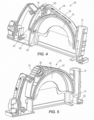
FIG. 4 is a perspective view of a shroud of the cut-off tool ofFIG. 1 . -
FIG. 5 is another perspective view of the shroud ofFIG. 5 . -
FIG. 6 is a side view of the cut-off tool ofFIG. 1 with the shroud ofFIGS. 4 and 5 removed. -
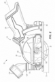
FIG. 7 is an enlarged cross-sectional view of the cut-off tool ofFIG. 1 viewed along lines 3-3 inFIG. 1 , illustrating an upper blade guard. -
FIG. 8 is an exploded view of the upper blade guard ofFIG. 7 and a detent mechanism. -
FIG. 9 is a perspective view of an arbor of the cut-off tool ofFIG. 1 . -
FIG. 10 is another perspective view of the cut-off tool ofFIG. 1 , including a vacuum attachment coupled to an exhaust port of the shroud ofFIG. 4 , the vacuum attachment illustrated in a first position. -
FIG. 11 is another perspective view of the cut-off tool ofFIG. 10 , illustrating the vacuum attachment in a second position. -
FIG. 12 is a cross-sectional view of a portion of the cut-off tool ofFIG. 1 , viewed along line 12-12 shown inFIG. 1 . -
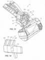
FIG. 13 is a cutaway perspective view of the cut-off tool ofFIG. 1 , illustrating a forward/reverse selector shuttle. -
FIG. 14 is a perspective view of the forward/reverse selector shuttle ofFIG. 13 . - Before any embodiments of the invention are explained in detail, it is to be understood that the invention is not limited in its application to the details of construction and the arrangement of components set forth in the following description or illustrated in the following drawings. The invention is capable of other embodiments and of being practiced or of being carried out in various ways. Also, it is to be understood that the phraseology and terminology used herein is for the purpose of description and should not be regarded as limiting.
-
FIGS. 1-14 illustrate all or portions of a cut-off tool, such as a compact multi-material cut offtool 10. The cut-offtool 10 includes ahousing 14, a motor 16 (FIG. 3 ) positioned within amotor housing portion 18 of thehousing 14, and anarbor 22 driven by themotor 16 to which a small diameter (e.g., 3 inch) cutting or grinding disk (hereinafter, "cutting disk 24") is attachable. Thehousing 14 also includes ahandle portion 26 extending transversely from themotor housing portion 18 and terminating in areceptacle 30 in which a battery pack (not shown) is received. The cut-offtool 10 also includes a trigger 34 (FIGS. 1 and6 ) protruding from thehandle portion 26 of thehousing 14, permitting a user to grasp thehandle portion 26 for maneuvering the cut-off tool 10 (without an auxiliary handle) while depressing thetrigger 34 to activate themotor 16. The cut-offtool 10 further includes a forward/reverse selector shuttle 38 (FIG. 6 ) located adjacent the front of thehandle portion 26 and forward of thetrigger 34, permitting the user to select either a forward or reverse rotational direction of themotor 16 with their thumb, for example, while maintaining their grasp on thehandle portion 26 with their index finger on thetrigger 34. - With reference to
FIGS. 1 and12-14 , thetrigger 34 and the forward/reverse selector shuttle 38 are connected to a combined motor activation/forward-reverse switch 140. The forward/reverse selector shuttle 38 includes anindicator portion 156 that is movable within thehandle portion 26 of thehousing 14, which includes a forward/reverse blade direction display window 172 (FIGS. 1 and3 ). Specifically, thedisplay window 172 is defined by first, second, andthird slots FIG. 1 ). The first andsecond slots handle portion 26, and the third slot 176C is between the first andsecond slots indicator portion 156 of the forward/reverse selector shuttle 38 includes asurface 180 in facing relationship with the first, second, andthird slots FIGS. 13 and 14 ). Thesurface 180 includes first, second, andthird sections FIG. 14 ). The first, second, andthird sections surface 180. Thethird section 184C is between the first andsecond sections display window 172 includes symbols to indicate to the user the rotational direction of themotor 16. The illustrateddisplay window 172 includes the letter "F" positioned adjacent thefirst slot 176A, the letter "R" positioned adjacent thesecond slot 176B, and a padlock icon positioned adjacent the third slot 176C, and between the letter "F" and the letter "R" (FIG. 1 ). The letter "F" corresponds to a forward direction of themotor 16, the letter "R" corresponds to a reverse direction of themotor 16, and the padlock icon corresponds to a lockout position of thetrigger 34 in which themotor 16 cannot be operated. - With continued reference to
FIGS. 1 and12-14 , movement of the forward/reverse selector shuttle 38 adjusts the color scheme of thedisplay window 172 to indicate the direction of themotor 16. Specifically, movement of the forward/reverse selector shuttle 38 positions the first, second, andthird sections third slots reverse selector shuttle 38 to the right from the frame of reference ofFIG. 13 aligns thesecond section 184B with theslot 176B, misaligns thefirst section 184A with theslot 176A, and misaligns thethird section 184C with the third slot 176C, thereby indicating to the user that the rotational direction of themotor 16 is in a reverse direction. Likewise, movement of the forward/reverse selector shuttle 38 to the left from the frame of reference ofFIG. 13 aligns thefirst section 184A with thefirst slot 176A, misaligns thesecond section 184B with thesecond slot 176B, and misaligns thethird section 184C with the third slot 176C, thereby indicating to the user that the rotational direction of themotor 16 is in a forward direction. When the forward/reverse selector shuttle 38 is in a middle position (i.e., when thethird section 184C is aligned with the third slot 176C, and the first andsecond sections second sections display window 172 indicates to the user that thetrigger 34 cannot be operated, or in other words, that the cut-offtool 10 is "locked out". The user must adjust the forward/reverse selector shuttle 38 to one of the positions indicating forward or reverse direction of themotor 16 before thetrigger 34 can be operated. - With reference to
FIGS. 4 and 5 , the cut-offtool 10 further includes a removable debris collection andshoe assembly 60, which includes ashroud 62 surrounding an upper blade guard 42 (FIG. 6 ), and anadjustable shoe 66 for sliding the cut-offtool 10 along a workpiece (FIGS. 4 and 5 ). Theshoe 66 is pivotably attached to theshroud 62, permitting adjustment of a cutting depth D (FIG. 2 ) of thecutting disk 24. Theshroud 62 includes anexhaust port 70 from which debris created during a workpiece cutting operation is discharged that is attachable to a vacuum source (not shown). - With reference to
FIG. 4 , theshroud 62 includes a forward/reverseblade direction indicator 64. Theindicator 64 corresponds to the direction themotor 16 is driving theblade 24 that is determined by the forward/reverse selector switch 38. Furthermore, debris may be expelled from theexhaust port 70 and/or a vacuum attachment (as further discussed below) when theblade 24 is driven in a forward direction by themotor 16 and a reverse direction by themotor 16. - With continued reference to
FIGS. 4 and 5 , theassembly 60 also includes an interior flange 74 (FIG. 5 ) at the front of theshroud 62 engageable with a front edge of theupper blade guard 42, and alatch 78 at the rear of theshroud 62, which collectively retain theassembly 60 to theupper blade guard 42. Thelatch 78 is pivotably attached to theshroud 62, and includes a finger 82 (FIG. 4 ) that protrudes into a correspondingaperture 86 in theupper blade guard 42 when thelatch 78 is moved to its biased position by acompression spring 90. Therefore, to remove theassembly 60 from theupper blade guard 42, the user needs only to pivot thelatch 78 against the bias of thespring 90 to remove thefinger 82 from theaperture 86. Thereafter, the user may lift theassembly 60 away from theupper blade guard 42. - With reference to
FIGS. 6-8 , thetool 10 includes a retainingclip 54 axially securing theupper blade guard 42 to thehousing 14 and a detent mechanism between theupper blade guard 42 and the retainingclip 54 for selectively holding theupper blade guard 42 in one of a plurality of positions relative to thehousing 14. Particularly, the orientation of theupper blade guard 42 is adjustable relative to themotor housing portion 18 about arotational axis 46 of the arbor 22 (FIG. 7 ). In the illustrated embodiment of thetool 10, the detent mechanism includes an array of detent recesses 50 (FIG. 6 ) defined in theupper blade guard 42 and a protrusion orspherical detent 58 formed on the retaining clip 54 (FIG. 7 ). Thespherical detent 58 is receivable in any of the detent recesses 50 to maintain theupper blade guard 42 in the desired position. In other embodiments, thedetent 58 may be formed on theupper blade guard 42 therecesses 50 may be defined in the retainingclip 54. - With continued reference to
FIGS. 6-8 , the retainingclip 54 further includes a stop 102 (FIG. 8 ) extending from a side of the retainingclip 54 and positioned betweenedges 106 of theupper blade guard 42. Thestop 102 engages theedges 106 for inhibiting rotation of theupper blade guard 42 about therotational axis 46 beyond theedges 106. Accordingly, theupper blade guard 42 is pivotable by 90 degrees about therotational axis 46 to facilitate different cutting/grinding operations by the user. In addition, the retainingclip 54 of thedetent mechanism 52 secures theupper blade guard 42 to the motor housing portion 18 (FIG. 6 ). - With reference to
FIG. 9 , the cut-offtool 10 also includes inner andouter flanges arbor 22 between which thecutting disk 24 is clamped. A back side of thecutting disk 24 is positioned against theinner flange 110. Thecutting disk 24 includes an aperture having an inner diameter nominally less than an outer diameter of thearbor 22. For example,FIG. 9 illustrates thearbor 22 having a 3/8 inch outer diameter for receiving cutting disks of a first size. - With continued reference to
FIG. 9 , theinner flange 110 further includes anadapter ring 118 integrally formed therewith. Theadapter ring 118 has a 7/16 inch outer diameter for receiving cutting disks of a second size with a nominally larger inner diameter. Therefore, theadapter ring 118 may center acutting disk 24 having a 7/16 inch nominal inner diameter on theflange 110 itself, rather than using thearbor 22 to center acutting disk 24 having a 3/8 inch nominal inner diameter (FIG. 7 ). In some embodiments, theinner flange 110 does not include theadapter ring 118. - With reference to
FIGS. 1 ,10, and 11 , the cut-offtool 10 also includes avacuum attachment 124 rotatably coupled to theexhaust port 70. Thevacuum attachment 124 is axially secured to theexhaust port 70 by a retainingclip 126, yet is capable of rotating relative to theexhaust port 70 by at least 180 degrees. For example, as shown inFIG. 10 , thevacuum attachment 124 is in a first position. As shown inFIG. 11 , thevacuum attachment 124 is in a second position in which thevacuum attachment 124 is rotated 180 degrees with respect to thevacuum attachment 124 ofFIG. 10 . - With continued reference to
FIGS. 1 ,10, and 11 , the cut-offtool 10 further includes a transparent shield or cover 130 attached to theshroud 62 to cover an opening in theshroud 62 andupper blade guard 42 through which thecutting disk 24 and thearbor 22 are visible. - With reference to
FIG. 3 , therotational axis 46 of themotor 16 and thearbor 22 is generally perpendicular (i.e., plus or minus about 10 degrees) to a direction of rotation of thecutting blade 24. In addition, therotational axis 46 of themotor 16 and thearbor 22 is generally perpendicular (i.e., plus or minus about 10 degrees) to a longitudinal axis 48 (FIG. 2 ) of thehandle portion 26. - With reference to
FIGS. 1 and2 , thecutting disk 24 may have an outer diameter of about 2 inches to about 4 inches. In the illustrated embodiment, thecutting disk 24 has an outer diameter of 3 inches. As described above, theshoe 66 is pivotably attached to theshroud 62 such that the cutting depth D of thecutting disk 24 is adjustable. For example, in one embodiment of the cut-offtool 10, the cutting depth D may be adjusted to about 0.6 inches or less. In another embodiment of the cut-offtool 10, the cutting depth D may be adjusted to about 0.65 inches or less. - Various features of the invention are set forth in the following numbered clauses.
- Clause 1. A cut-off tool comprising:
- a housing;
- an arbor supported by the housing for relative movement therewith;
- a cutting disk attachable to the arbor;
- a motor coupled to the arbor to provide torque thereto;
- a battery pack removably coupled to the housing for providing power to the motor; and
- a switch operable to adjust rotation of the motor between a first rotational direction and an opposite, second direction for selectively rotating the cutting disk in the first rotational direction or second rotational direction, respectively.
- Clause 2. The cut-off tool of clause 1, wherein the housing includes a handle portion, and wherein the switch is positioned adjacent the handle portion.
-
Clause 3. The cut-off tool of clause 1, further comprising:- a trigger for actuating the switch and selectively activating the motor; and
- a shuttle proximate the trigger for actuating the switch between a first state, in which the motor and cutting disk are driven in the first rotational direction in response to motor activation by the trigger, and a second state, in which the motor and cutting disk are driven in the second rotational direction in response to motor activation by the trigger.
- Clause 4. The cut-off tool of
clause 3, wherein the shuttle is movable between a plurality of positions relative to the housing, wherein a first position of the shuttle corresponds to the first rotational direction of the motor and cutting disk, and wherein a second position of the shuttle corresponds to the second rotational direction of the motor and cutting disk. - Clause 5. The cut-off tool of clause 4, wherein the shuttle is movable to a third position intermediate the first position and the second position, and wherein the third position corresponds to a lockout position of the switch in which the motor remains deactivated in response to the trigger actuating the switch.
- Clause 6. The cut-off tool of clause 4, wherein the housing includes a display window, wherein the shuttle includes an indicator portion adjustably positioned within the display window, and wherein a position of the indicator portion relative to the display window indicates the rotational direction of the motor and cutting disk.
- Clause 7. The cut-off tool of clause 6, wherein the display window is defined by a plurality of slots, wherein the indicator portion includes a plurality of sections positionable relative to the slots by adjustment of the shuttle, wherein one of the sections is aligned with one of the slots to indicate the first rotational direction of the motor and cutting disk, and wherein another one of the sections is aligned with another one of the slots to indicate the second rotational direction of the motor and cutting disk.
- Clause 8. A cut-off tool comprising:
- a housing;
- an arbor supported by the housing for relative movement therewith;
- a cutting disk attachable to the arbor;
- a blade guard surrounding an upper portion of the cutting disk;
- a retaining clip securing the blade guard to the housing; and
- a detent mechanism between the blade guard and the retaining clip for selectively holding the blade guard in one of a plurality of positions relative to the housing.
- Clause 9. The cut-off tool of clause 8, wherein the detent mechanism includes a protrusion defined on one of the retaining clip or the blade guard, and a plurality of recesses defined in the other of the retaining clip or the blade guard in which the protrusion is receivable to hold the blade guard in one of the plurality of positions relative to the housing.
-
Clause 10. The cut-off tool of clause 9, wherein the arbor defines a rotational axis, wherein the recesses are arranged about the rotational axis, and wherein each of the recesses corresponds to a position of the blade guard relative to the housing. - Clause 11. The cut-off tool of clause 9, wherein the retaining clip includes the protrusion, and wherein the blade guard includes the recesses.
-
Clause 12. The cut-off tool of clause 8, wherein the retaining clip includes a stop positioned between two edges on the blade guard, and wherein the stop is configured to engage the edges for inhibiting rotation of the blade guard about a rotational axis of the arbor. - Clause 13. The cut-off tool of clause 8, further comprising a shroud removably coupled to the blade guard, wherein the shroud includes an exhaust port through which debris created during a cutting operation is discharged.
-
Clause 14. The cut-off tool of clause 13, further comprising a vacuum attachment rotatably coupled to the exhaust port between a plurality of different rotational positions relative to the shroud. - Clause 15. The cut-off tool of clause 8, further comprising a shroud removably coupled to the blade guard, wherein the shroud includes
- a latch movable between a first position in which the shroud is secured to the blade guard, and a second position in which the shroud is removable from the blade guard, and
- a biasing member for biasing the latch toward the first position.
-
Clause 16. The cut-off tool of clause 15, further comprising a shoe pivotably coupled to the shroud for adjusting a cutting depth of the cutting disk. - Clause 17. The cut-off tool of clause 15, further comprising a cover closing an opening in the shroud and blade guard through which the cutting disk and the arbor are visible, wherein the cover is formed from a transparent material.
-
Clause 18. A cut-off tool comprising:- a housing;
- an arbor supported by the housing for relative movement therewith;
- a flange coupled for co-rotation with the arbor against which a cutting disk is clamped; and
- an adapter ring coupled for co-rotation with the flange,
- wherein an outer diameter of the adapter ring is nominally less than an inner diameter of an aperture in the cutting disk for aligning the cutting disk with the arbor.
- Clause 19. The cut-off tool of
clause 18, wherein the adapter ring is integrally formed with the flange as a single piece. - Clause 20. The cut-off tool of
clause 18, wherein the flange is a first flange, wherein the arbor further includes a second flange spaced from the first flange along a rotational axis of the arbor, and wherein the cutting disk is clamped between the first flange and the second flange. - Clause 21. The cut-off tool of
clause 18, wherein the outer diameter of the adapter ring is a first outer diameter, wherein the arbor has a second outer diameter that is less than the first outer diameter, and wherein the first outer diameter corresponds to a cutting disk having the inner diameter of a first size, and the second outer diameter corresponds to a cutting disk having the inner diameter of a second size.
Claims (14)
- A cut-off tool comprising:a housing;an arbor supported by the housing for relative movement therewith;a cutting disk attachable to the arbor;a blade guard surrounding an upper portion of the cutting disk;a retaining clip securing the blade guard to the housing; anda detent mechanism between the blade guard and the retaining clip for selectively holding the blade guard in one of a plurality of positions relative to the housing.
- The cut-off tool of claim 1, wherein the detent mechanism includes a protrusion defined on one of the retaining clip or the blade guard, and a plurality of recesses defined in the other of the retaining clip or the blade guard in which the protrusion is receivable to hold the blade guard in one of the plurality of positions relative to the housing.
- The cut-off tool of claim 2, wherein the arbor defines a rotational axis, wherein the recesses are arranged about the rotational axis, and wherein each of the recesses corresponds to a position of the blade guard relative to the housing.
- The cut-off tool of claim 2, wherein the retaining clip includes the protrusion, and wherein the blade guard includes the recesses.
- The cut-off tool of claim 1, wherein the retaining clip includes a stop positioned between two edges on the blade guard, and wherein the stop is configured to engage the edges for inhibiting rotation of the blade guard about a rotational axis of the arbor.
- The cut-off tool of claim 1, further comprising a shroud removably coupled to the blade guard, wherein the shroud includes an exhaust port through which debris created during a cutting operation is discharged.
- The cut-off tool of claim 6, further comprising a vacuum attachment rotatably coupled to the exhaust port between a plurality of different rotational positions relative to the shroud.
- The cut-off tool of claim 1, further comprising a shroud removably coupled to the blade guard, wherein the shroud includesa latch movable between a first position in which the shroud is secured to the blade guard, and a second position in which the shroud is removable from the blade guard, anda biasing member for biasing the latch toward the first position.
- The cut-off tool of claim 8, further comprising a shoe pivotably coupled to the shroud for adjusting a cutting depth of the cutting disk.
- The cut-off tool of claim 8, further comprising a cover closing an opening in the shroud and blade guard through which the cutting disk and the arbor are visible, wherein the cover is formed from a transparent material.
- A cut-off tool comprising:a housing;an arbor supported by the housing for relative movement therewith;a flange coupled for co-rotation with the arbor against which a cutting disk is clamped; andan adapter ring coupled for co-rotation with the flange,wherein an outer diameter of the adapter ring is nominally less than an inner diameter of an aperture in the cutting disk for aligning the cutting disk with the arbor.
- The cut-off tool of claim 11, wherein the adapter ring is integrally formed with the flange as a single piece.
- The cut-off tool of claim 11, wherein the flange is a first flange, wherein the arbor further includes a second flange spaced from the first flange along a rotational axis of the arbor, and wherein the cutting disk is clamped between the first flange and the second flange.
- The cut-off tool of claim 11, wherein the outer diameter of the adapter ring is a first outer diameter, wherein the arbor has a second outer diameter that is less than the first outer diameter, and wherein the first outer diameter corresponds to a cutting disk having the inner diameter of a first size, and the second outer diameter corresponds to a cutting disk having the inner diameter of a second size.
Applications Claiming Priority (4)
| Application Number | Priority Date | Filing Date | Title |
|---|---|---|---|
| US201862663403P | 2018-04-27 | 2018-04-27 | |
| US201862675236P | 2018-05-23 | 2018-05-23 | |
| EP19793663.6A EP3784429B1 (en) | 2018-04-27 | 2019-04-22 | Compact multi-material cut-off tool |
| PCT/US2019/028484 WO2019209699A1 (en) | 2018-04-27 | 2019-04-22 | Compact multi-material cut-off tool |
Related Parent Applications (1)
| Application Number | Title | Priority Date | Filing Date |
|---|---|---|---|
| EP19793663.6A Division EP3784429B1 (en) | 2018-04-27 | 2019-04-22 | Compact multi-material cut-off tool |
Publications (2)
| Publication Number | Publication Date |
|---|---|
| EP4324583A2 true EP4324583A2 (en) | 2024-02-21 |
| EP4324583A3 EP4324583A3 (en) | 2024-07-10 |
Family
ID=68290818
Family Applications (2)
| Application Number | Title | Priority Date | Filing Date |
|---|---|---|---|
| EP24150632.8A Pending EP4324583A3 (en) | 2018-04-27 | 2019-04-22 | Compact multi-material cut-off tool |
| EP19793663.6A Active EP3784429B1 (en) | 2018-04-27 | 2019-04-22 | Compact multi-material cut-off tool |
Family Applications After (1)
| Application Number | Title | Priority Date | Filing Date |
|---|---|---|---|
| EP19793663.6A Active EP3784429B1 (en) | 2018-04-27 | 2019-04-22 | Compact multi-material cut-off tool |
Country Status (4)
| Country | Link |
|---|---|
| US (2) | US20190329337A1 (en) |
| EP (2) | EP4324583A3 (en) |
| CN (1) | CN214443508U (en) |
| WO (1) | WO2019209699A1 (en) |
Families Citing this family (13)
| Publication number | Priority date | Publication date | Assignee | Title |
|---|---|---|---|---|
| US11772224B2 (en) | 2020-04-27 | 2023-10-03 | Techtronic Cordless Gp | Compact multi-material cut-off tool |
| US11027392B1 (en) * | 2020-04-27 | 2021-06-08 | Techtronic Cordless Gp | Compact multi-material cut-off tool |
| US12263615B2 (en) | 2020-11-23 | 2025-04-01 | Milwaukee Electric Tool Corporation | Circular saw |
| US12330225B2 (en) * | 2021-06-28 | 2025-06-17 | Milwaukee Electric Tool Corporation | Cut-off saw including forward and reverse blade rotation |
| WO2023010537A1 (en) * | 2021-08-06 | 2023-02-09 | Black & Decker Inc. | Circular saw with a shroud |
| WO2023010528A1 (en) | 2021-08-06 | 2023-02-09 | Black & Decker Inc. | Circular saw with a shroud |
| WO2023065028A1 (en) | 2021-10-22 | 2023-04-27 | Ring Rescue Inc. | Ring cutter for safely transecting a ring trapped on an appendage |
| US12465982B2 (en) * | 2022-02-24 | 2025-11-11 | Techtronic Cordless Gp | Track saw including plunge lockout mechanism |
| CN223264879U (en) | 2022-03-18 | 2025-08-26 | 米沃奇电动工具公司 | Circular saw and orbital saw assembly configured to cut in a workpiece |
| US12083613B2 (en) | 2022-10-18 | 2024-09-10 | Techtronic Cordless Gp | Track saw including plunge lockout mechanism |
| WO2024104060A1 (en) * | 2022-11-16 | 2024-05-23 | 南京泉峰科技有限公司 | Cutting tool |
| DE102023201268A1 (en) | 2023-02-15 | 2024-08-22 | Robert Bosch Gesellschaft mit beschränkter Haftung | Extraction amplifier and system with a hand-held circular saw and an extraction amplifier |
| USD1089340S1 (en) | 2023-06-22 | 2025-08-19 | Ring Rescue Inc. | Ring cutter |
Family Cites Families (52)
| Publication number | Priority date | Publication date | Assignee | Title |
|---|---|---|---|---|
| US3339597A (en) * | 1965-10-22 | 1967-09-05 | Black & Decker Mfg Co | Dust-collecting system for saw machine |
| US3616556A (en) * | 1969-09-04 | 1971-11-02 | Heller & Co Walter E | Movable display |
| US4112271A (en) * | 1976-12-20 | 1978-09-05 | Sperry Rand Corporation | Counter device associated with switch actuator of electrical shaver to determine battery recharging and use |
| US4454901A (en) * | 1979-04-02 | 1984-06-19 | Wilfred Thorsness | Multi-directional rotary saw |
| BR7903150A (en) * | 1979-05-21 | 1980-11-25 | Rockwell Brasil Ind Com | TABLE SAW |
| US5014793A (en) * | 1989-04-10 | 1991-05-14 | Measurement Specialties, Inc. | Variable speed DC motor controller apparatus particularly adapted for control of portable-power tools |
| US5084972A (en) * | 1991-01-25 | 1992-02-04 | Waugh Ricky L | Device for collecting dust from a portable circular saw |
| US5203761A (en) * | 1991-06-17 | 1993-04-20 | Sealed Air Corporation | Apparatus for fabricating dunnage material from continuous web material |
| US6736037B2 (en) * | 1999-03-22 | 2004-05-18 | Ethan Dean | Coping saw |
| CN2420088Y (en) * | 2000-05-15 | 2001-02-21 | 铨宝工业股份有限公司 | An electric drill seat shell structure with a cladding chuck |
| US6536371B2 (en) * | 2001-08-01 | 2003-03-25 | One World Technologies, Inc. | Rotary direction indicator |
| US7282818B2 (en) * | 2002-04-10 | 2007-10-16 | Credo Technology Corporation | Power hand tool having a proximity detector |
| GB0226523D0 (en) * | 2002-11-14 | 2002-12-18 | Black & Decker Inc | Electric motor driven hand-held tool |
| US6925917B2 (en) * | 2002-12-03 | 2005-08-09 | Robert J. Tilley | Tool provided with irrigation for transection of a band, ring or the like and method of use |
| JP4646016B2 (en) * | 2004-01-30 | 2011-03-09 | セイコーインスツル株式会社 | A watch with a calendar mechanism including the 1st day wheel and the 2nd day wheel |
| US7231858B2 (en) * | 2004-04-13 | 2007-06-19 | Robert Bosch Gmbh | Table saw having a measurement and display system |
| US7059947B2 (en) * | 2004-05-12 | 2006-06-13 | The Stanley Works | Portable rail cutting apparatus |
| DE102004038788A1 (en) * | 2004-08-09 | 2006-02-23 | Robert Bosch Gmbh | Cordless hand tool |
| US20060169111A1 (en) * | 2005-02-02 | 2006-08-03 | Kozlowski Kevin M | Saw blade for drywall, saw apparatus utilizing saw blade and method |
| US7465328B2 (en) * | 2005-07-22 | 2008-12-16 | Black & Decker Inc. | Dust collector for a power tool |
| WO2009070357A1 (en) * | 2007-11-28 | 2009-06-04 | Milwaukee Electric Tool Corporation | Pipe cutter |
| DE102008023324A1 (en) * | 2008-05-13 | 2009-11-19 | Aeg Electric Tools Gmbh | Protective hood for a power tool, in particular an angle grinder and power tool with such a protective hood |
| US20100071921A1 (en) * | 2008-09-24 | 2010-03-25 | Icc Innovative Concepts Corporation | Environmentally advantageous electric drill with efficiency promoting charge state indicator |
| JP2011073087A (en) * | 2009-09-29 | 2011-04-14 | Hitachi Koki Co Ltd | Fastening machine tool |
| EP2388107B1 (en) * | 2009-12-18 | 2019-09-04 | Techtronic Power Tools Technology Limited | Multi-function tool system |
| DE102010038676A1 (en) * | 2010-07-30 | 2012-02-02 | Hilti Aktiengesellschaft | circular saw |
| JP5918237B2 (en) * | 2010-08-18 | 2016-05-18 | カズデイ、ジェイコブ | Replaceable zero-gap circular saw |
| US9339938B2 (en) * | 2010-10-08 | 2016-05-17 | Milwaukee Electric Tool Corporation | Powered cutting tool |
| US20130008677A1 (en) * | 2011-07-08 | 2013-01-10 | Chen Huifu | Multi-head power tool |
| US20130047812A1 (en) * | 2011-08-26 | 2013-02-28 | WaneShear Technologies LLC | Locking Taper Saw Blade Mounting Assembly and Method |
| US10512246B2 (en) * | 2012-02-02 | 2019-12-24 | Doskocil Manufacturing Company, Inc. | Nail or claw trimmer for use with pets |
| US8622166B1 (en) * | 2012-08-30 | 2014-01-07 | University Of Puerto Rico | Switch-actuated joystick for power wheelchairs |
| JP6283161B2 (en) * | 2012-12-19 | 2018-02-21 | 株式会社マキタ | Work machine with operation rod |
| DE102013020427B4 (en) * | 2013-01-31 | 2018-04-05 | Makita Corporation | Working machine with operating staff |
| US9355511B2 (en) * | 2013-02-07 | 2016-05-31 | Schlage Lock Company Llc | Apparatuses and methods for displaying feedback indicators via a keypad |
| US9156148B2 (en) * | 2013-05-10 | 2015-10-13 | Snap-On Incorporated | Preset electronic torque tool |
| JP2015080896A (en) | 2013-10-22 | 2015-04-27 | 日立工機株式会社 | Electric power tool |
| JP6174451B2 (en) * | 2013-10-22 | 2017-08-02 | 日東工器株式会社 | Electric screwdriver |
| CN103676282A (en) * | 2013-12-23 | 2014-03-26 | 合肥京东方光电科技有限公司 | Touch screen and display screen separation device and method |
| DE102014107494A1 (en) * | 2014-05-27 | 2015-12-03 | C. & E. Fein Gmbh | Power tool, in particular screwdriver, with direction switch |
| US9475172B2 (en) * | 2014-07-15 | 2016-10-25 | Milwaukee Electric Tool Corporation | Adjustable guard for power tool |
| EP3653139B1 (en) * | 2014-10-30 | 2024-07-03 | Stryker Corporation | Surgical tool with an aseptic power module that enters a specific operating state based on the type of handpiece to which the module is attached |
| US20160348893A1 (en) * | 2015-06-01 | 2016-12-01 | I-Sin Peng | Ventilation device |
| JP6297521B2 (en) * | 2015-06-03 | 2018-03-20 | 株式会社東海理化電機製作所 | Switch device |
| EP3269323B1 (en) * | 2015-08-12 | 2019-03-20 | medineering GmbH | Medical holding arm with annular led display means |
| JP2017106753A (en) * | 2015-12-07 | 2017-06-15 | セイコーエプソン株式会社 | Electronic clock and display control method of electronic clock |
| DE102015226087A1 (en) * | 2015-12-18 | 2017-06-22 | Robert Bosch Gmbh | Hand tool with adjustable direction of rotation |
| JP2017124462A (en) * | 2016-01-13 | 2017-07-20 | 株式会社マキタ | Cutting machine |
| JP6814032B2 (en) * | 2016-11-24 | 2021-01-13 | 株式会社マキタ | Electric work machine |
| US20180290322A1 (en) * | 2017-04-10 | 2018-10-11 | Nanjing Chervon Industry Co., Ltd. | Hand-held cutting tool |
| US11896285B2 (en) * | 2018-03-14 | 2024-02-13 | Gyrus Acmi, Inc. | Device with movable buttons or switches and visual indicator |
| IT201800004792A1 (en) * | 2018-04-23 | 2019-10-23 | Drill for drilling railway sleepers |
-
2019
- 2019-04-22 EP EP24150632.8A patent/EP4324583A3/en active Pending
- 2019-04-22 US US16/390,483 patent/US20190329337A1/en active Pending
- 2019-04-22 WO PCT/US2019/028484 patent/WO2019209699A1/en not_active Ceased
- 2019-04-22 EP EP19793663.6A patent/EP3784429B1/en active Active
- 2019-04-22 CN CN201990000659.3U patent/CN214443508U/en active Active
-
2025
- 2025-01-16 US US19/024,928 patent/US20250153256A1/en active Pending
Also Published As
| Publication number | Publication date |
|---|---|
| WO2019209699A1 (en) | 2019-10-31 |
| EP3784429A4 (en) | 2022-04-06 |
| EP3784429B1 (en) | 2024-01-24 |
| US20190329337A1 (en) | 2019-10-31 |
| EP3784429A1 (en) | 2021-03-03 |
| EP4324583A3 (en) | 2024-07-10 |
| US20250153256A1 (en) | 2025-05-15 |
| CN214443508U (en) | 2021-10-22 |
Similar Documents
| Publication | Publication Date | Title |
|---|---|---|
| US20250153256A1 (en) | Compact multi-material cut-off tool | |
| US7526867B2 (en) | Tool with clamping apparatus and an improved scrolling mechanism | |
| CA2790967C (en) | Saw assembly with floating bearing for worm drive and motor shaft | |
| CA2790966C (en) | Spring biased base with offset pivot point | |
| US10173345B2 (en) | Dust collection cover for cutting devices | |
| EP3845350A1 (en) | Circular saw and method of manufacturing a circular saw | |
| EP3903977B1 (en) | Compact multi-material cut-off tool | |
| EP2666592A1 (en) | Hand-held electric cutting machine | |
| CA2790968C (en) | Circular saw guard system | |
| US20040060178A1 (en) | Circular saw | |
| EP3388177A2 (en) | Hand-held cutting tool | |
| CA2790976C (en) | Lockout forward flip lever for power saw | |
| CA2790992C (en) | Base lever with release stop and lock stop | |
| EP2535154A1 (en) | Covering device for cutting machine and cutting machine having the same | |
| CA3190069A1 (en) | Track saw including plunge lockout mechanism | |
| CA2791316C (en) | Base with beveled lateral side surface | |
| CA2790990C (en) | Power saw crown molding cutting guide | |
| CA2790965C (en) | Power saw miter cutting guide | |
| US20050144792A1 (en) | In-line sanding paddle with multiple extensions having certain tensile strengths | |
| AU2003248455A1 (en) | Clamping apparatus for a tool component and an improved scrolling mechanism | |
| GB2416328A (en) | Circular saw with removable blade cover | |
| EP1767299A1 (en) | Observation window for portable circular saws |
Legal Events
| Date | Code | Title | Description |
|---|---|---|---|
| PUAI | Public reference made under article 153(3) epc to a published international application that has entered the european phase |
Free format text: ORIGINAL CODE: 0009012 |
|
| STAA | Information on the status of an ep patent application or granted ep patent |
Free format text: STATUS: THE APPLICATION HAS BEEN PUBLISHED |
|
| AC | Divisional application: reference to earlier application |
Ref document number: 3784429 Country of ref document: EP Kind code of ref document: P |
|
| AK | Designated contracting states |
Kind code of ref document: A2 Designated state(s): AL AT BE BG CH CY CZ DE DK EE ES FI FR GB GR HR HU IE IS IT LI LT LU LV MC MK MT NL NO PL PT RO RS SE SI SK SM TR |
|
| REG | Reference to a national code |
Ref country code: DE Ref legal event code: R079 Free format text: PREVIOUS MAIN CLASS: B23D0045160000 Ipc: B23D0047120000 |
|
| RIC1 | Information provided on ipc code assigned before grant |
Ipc: B25F 5/00 20060101ALI20240306BHEP Ipc: B27G 19/04 20060101ALI20240306BHEP Ipc: B27B 9/02 20060101ALI20240306BHEP Ipc: B23D 47/12 20060101AFI20240306BHEP |
|
| PUAL | Search report despatched |
Free format text: ORIGINAL CODE: 0009013 |
|
| AK | Designated contracting states |
Kind code of ref document: A3 Designated state(s): AL AT BE BG CH CY CZ DE DK EE ES FI FR GB GR HR HU IE IS IT LI LT LU LV MC MK MT NL NO PL PT RO RS SE SI SK SM TR |
|
| RIC1 | Information provided on ipc code assigned before grant |
Ipc: B25F 5/00 20060101ALI20240531BHEP Ipc: B27G 19/04 20060101ALI20240531BHEP Ipc: B27B 9/02 20060101ALI20240531BHEP Ipc: B23D 47/12 20060101AFI20240531BHEP |
|
| STAA | Information on the status of an ep patent application or granted ep patent |
Free format text: STATUS: REQUEST FOR EXAMINATION WAS MADE |
|
| 17P | Request for examination filed |
Effective date: 20250109 |