EP4322707A1 - Ceramic heater, and method for manufacturing ceramic heater - Google Patents
Ceramic heater, and method for manufacturing ceramic heater Download PDFInfo
- Publication number
- EP4322707A1 EP4322707A1 EP22784659.9A EP22784659A EP4322707A1 EP 4322707 A1 EP4322707 A1 EP 4322707A1 EP 22784659 A EP22784659 A EP 22784659A EP 4322707 A1 EP4322707 A1 EP 4322707A1
- Authority
- EP
- European Patent Office
- Prior art keywords
- ceramic
- heat
- resistor body
- generation resistor
- metal component
- Prior art date
- Legal status (The legal status is an assumption and is not a legal conclusion. Google has not performed a legal analysis and makes no representation as to the accuracy of the status listed.)
- Pending
Links
- 239000000919 ceramic Substances 0.000 title claims abstract description 121
- 238000004519 manufacturing process Methods 0.000 title claims description 7
- 238000000034 method Methods 0.000 title description 4
- 230000020169 heat generation Effects 0.000 claims abstract description 53
- 229910052751 metal Inorganic materials 0.000 claims abstract description 53
- 239000002184 metal Substances 0.000 claims abstract description 53
- 238000005259 measurement Methods 0.000 claims abstract description 45
- 239000002245 particle Substances 0.000 claims description 46
- 239000002923 metal particle Substances 0.000 claims description 24
- 239000000976 ink Substances 0.000 description 14
- XLYOFNOQVPJJNP-UHFFFAOYSA-N water Substances O XLYOFNOQVPJJNP-UHFFFAOYSA-N 0.000 description 9
- PNEYBMLMFCGWSK-UHFFFAOYSA-N aluminium oxide Inorganic materials [O-2].[O-2].[O-2].[Al+3].[Al+3] PNEYBMLMFCGWSK-UHFFFAOYSA-N 0.000 description 7
- 230000000052 comparative effect Effects 0.000 description 5
- 238000005406 washing Methods 0.000 description 5
- 239000000843 powder Substances 0.000 description 4
- 239000002002 slurry Substances 0.000 description 3
- WFKWXMTUELFFGS-UHFFFAOYSA-N tungsten Chemical compound [W] WFKWXMTUELFFGS-UHFFFAOYSA-N 0.000 description 3
- XEEYBQQBJWHFJM-UHFFFAOYSA-N Iron Chemical compound [Fe] XEEYBQQBJWHFJM-UHFFFAOYSA-N 0.000 description 2
- ZOKXTWBITQBERF-UHFFFAOYSA-N Molybdenum Chemical compound [Mo] ZOKXTWBITQBERF-UHFFFAOYSA-N 0.000 description 2
- 230000015572 biosynthetic process Effects 0.000 description 2
- 239000004020 conductor Substances 0.000 description 2
- 239000011521 glass Substances 0.000 description 2
- 238000005304 joining Methods 0.000 description 2
- 239000000203 mixture Substances 0.000 description 2
- 239000011347 resin Substances 0.000 description 2
- 229920005989 resin Polymers 0.000 description 2
- 238000005245 sintering Methods 0.000 description 2
- 239000002904 solvent Substances 0.000 description 2
- 238000010792 warming Methods 0.000 description 2
- 239000011230 binding agent Substances 0.000 description 1
- 239000006185 dispersion Substances 0.000 description 1
- 238000009826 distribution Methods 0.000 description 1
- 230000000694 effects Effects 0.000 description 1
- 230000001747 exhibiting effect Effects 0.000 description 1
- 239000011810 insulating material Substances 0.000 description 1
- 229910052742 iron Inorganic materials 0.000 description 1
- 239000000463 material Substances 0.000 description 1
- 238000002844 melting Methods 0.000 description 1
- 230000008018 melting Effects 0.000 description 1
- 238000012986 modification Methods 0.000 description 1
- 230000004048 modification Effects 0.000 description 1
- 229910052573 porcelain Inorganic materials 0.000 description 1
- 238000005476 soldering Methods 0.000 description 1
- 239000007787 solid Substances 0.000 description 1
- 229910052721 tungsten Inorganic materials 0.000 description 1
- 239000010937 tungsten Substances 0.000 description 1
Images




Classifications
-
- H—ELECTRICITY
- H05—ELECTRIC TECHNIQUES NOT OTHERWISE PROVIDED FOR
- H05B—ELECTRIC HEATING; ELECTRIC LIGHT SOURCES NOT OTHERWISE PROVIDED FOR; CIRCUIT ARRANGEMENTS FOR ELECTRIC LIGHT SOURCES, IN GENERAL
- H05B3/00—Ohmic-resistance heating
- H05B3/40—Heating elements having the shape of rods or tubes
- H05B3/42—Heating elements having the shape of rods or tubes non-flexible
- H05B3/48—Heating elements having the shape of rods or tubes non-flexible heating conductor embedded in insulating material
-
- H—ELECTRICITY
- H05—ELECTRIC TECHNIQUES NOT OTHERWISE PROVIDED FOR
- H05B—ELECTRIC HEATING; ELECTRIC LIGHT SOURCES NOT OTHERWISE PROVIDED FOR; CIRCUIT ARRANGEMENTS FOR ELECTRIC LIGHT SOURCES, IN GENERAL
- H05B3/00—Ohmic-resistance heating
- H05B3/10—Heating elements characterised by the composition or nature of the materials or by the arrangement of the conductor
- H05B3/12—Heating elements characterised by the composition or nature of the materials or by the arrangement of the conductor characterised by the composition or nature of the conductive material
- H05B3/14—Heating elements characterised by the composition or nature of the materials or by the arrangement of the conductor characterised by the composition or nature of the conductive material the material being non-metallic
- H05B3/141—Conductive ceramics, e.g. metal oxides, metal carbides, barium titanate, ferrites, zirconia, vitrous compounds
-
- H—ELECTRICITY
- H05—ELECTRIC TECHNIQUES NOT OTHERWISE PROVIDED FOR
- H05B—ELECTRIC HEATING; ELECTRIC LIGHT SOURCES NOT OTHERWISE PROVIDED FOR; CIRCUIT ARRANGEMENTS FOR ELECTRIC LIGHT SOURCES, IN GENERAL
- H05B2203/00—Aspects relating to Ohmic resistive heating covered by group H05B3/00
- H05B2203/002—Heaters using a particular layout for the resistive material or resistive elements
- H05B2203/003—Heaters using a particular layout for the resistive material or resistive elements using serpentine layout
-
- H—ELECTRICITY
- H05—ELECTRIC TECHNIQUES NOT OTHERWISE PROVIDED FOR
- H05B—ELECTRIC HEATING; ELECTRIC LIGHT SOURCES NOT OTHERWISE PROVIDED FOR; CIRCUIT ARRANGEMENTS FOR ELECTRIC LIGHT SOURCES, IN GENERAL
- H05B2203/00—Aspects relating to Ohmic resistive heating covered by group H05B3/00
- H05B2203/013—Heaters using resistive films or coatings
Definitions
- the present invention relates to a ceramic heater used for, for example, a warm water washing toilet seat, a fan heater, an electric water heater, a 24-hour bath system, a soldering iron, a hair straightener, and the like, and a production method for the ceramic heater.
- a heat exchange unit having a container (heat exchanger) made of resin is used, and in the heat exchange unit, a ceramic heater having an elongated pipe shape is provided for warming washing water contained in a heat exchanger.
- a ceramic sheet printed with a heater wiring circuit serving as a heat-generation resistor body is wrapped around a cylindrical porcelain tube made of ceramic, and these are sintered to obtain a ceramic heater (see Patent Document 1).
- Patent Document 1 Japanese Patent Application Laid-Open (kokai) No. H09-7739
- the ceramic heater is downsized, the area of a part where heater wiring can be formed, of the ceramic sheet, is reduced. Therefore, in order to obtain the same amount of heat as in the conventional ceramic heater by one circuit, it is necessary to increase the wiring resistance, or ensure a wiring length equivalent to the conventional wiring length by reducing the wire-line width and increasing the number of times of folding.
- the wiring circuit of the heater is formed by printing an ink paste containing metal particles. Therefore, in consideration of blur in printing, there is a limitation in narrowing the wire-line width (e.g., about 0.3 mm). Thus, it is necessary to increase the wiring resistance, and for this purpose, ceramic particles such as alumina are added to the ink paste.
- an object of the present invention is to provide a ceramic heater in which the resistance of a heat-generation resistor body is increased while disconnection is suppressed, and a production method for the ceramic heater.
- a ceramic heater of the present invention is a ceramic heater comprising a heat-generation resistor body embedded in a base, wherein the heat-generation resistor body includes a metal component and a ceramic component, and when ten different measurement parts of 10 um squares in a transverse cross-section of the heat-generation resistor body are measured, an average content of the metal component is not less than 35% by area but less than 50% by area, and a minimum content of the metal component is not less than 30% by area.
- the "minimum content of the metal component" is set to such a level that the content of the ceramic component does not vary in each measurement part, occurrence of disconnection due to local formation of such an area where there is an excessively large amount of ceramic component can be suppressed.
- the metal component aggregates and forms connection over the entirety in the heat-generation resistor body, thus stably exhibiting high conductivity.
- a maximum content of the metal component may be not greater than 80% by area.
- an electric resistivity of the heat-generation resistor body per area of 100 ⁇ m 2 at 25°C when a thickness thereof is 25 um mae be not less than 0.02 ⁇ .
- the electric resistance of the heat-generation resistor body can be assuredly increased.
- a production method for a ceramic heater of the present invention is a production method for a ceramic heater, comprising: a ceramic base producing step of producing a ceramic base; and an application step of applying or printing an ink to be a heat-generation resistor body, around the ceramic base, wherein the ink contains metal particles and ceramic particles, an average particle size of the metal particles is 0.5 to 2.0 um, and an average particle size of the ceramic particles is 0.2 to 2.0 um.
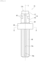
- FIG. 1 is a front view showing a ceramic heater 11 according to the embodiment of the present invention.
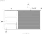
- FIG. 2 is a development view showing a ceramic sheet 19 of the ceramic heater 11.
- FIG. 3 is a development view schematically showing heater wiring circuits 40a, 40b included in FIG. 2 .
- the ceramic heater 11 according to the embodiment of the present invention can be used for warming washing water in a heat exchanger of a heat exchange unit of a warm water washing toilet seat, for example.
- the ceramic heater 11 includes a tubular base (ceramic base) 13 having a heat-generation resistor body 40 embedded therein, and a flange 30 which is joined to the outer circumference of the ceramic base 13 via a joining member 20 and which is made of ceramic and has a ring shape, or a ring shape with ends.
- the ceramic base 13 includes a cylindrical support body 17 made of ceramic, and a ceramic sheet 19 wrapped around the outer circumference of the support body 17.
- the support body 17 has a through hole 17h in an axial-line-O direction thereof. Then, in the heat exchanger, water flowing inside the through hole 17h is heated by the ceramic heater 11 and water in the gap between the inner wall of the heat exchanger and the outer circumference of the ceramic heater is also heated by the ceramic heater 11.
- the support body 17 and the ceramic sheet 19 can be formed from alumina, for example.
- the ceramic sheet 19 does not completely cover the outer circumference of the support body 17, and a slit 13s extending along the axial-line-O direction of the support body 17 is formed at a wrap-meeting part 19a of the ceramic sheet 19.
- a heat-generation resistor body 40 composed of a plurality of heater wiring circuits 40a, 40b having meandering pattern shapes is formed by printing or the like.
- Each heater wiring circuit 40a, 40b of the heat-generation resistor body 40 is formed such that folded portions 40m at both ends of a plurality of wiring portions 40L (see upper drawing in FIG. 3 ) mutually extending along the axial-line-O direction extend in the width direction and are connected to ends of the adjacent wiring portions 40L.
- the wiring portions at both ends of each heater wiring circuit 40a, 40b are connected integrally to the respective ones of three pad-shaped connection terminals 41, 42a, 42b at one end in the axial-line-O direction.
- wiring portions 40L1, 40L2 at both ends of the heater wiring circuit 40a are respectively connected to the connection terminal 41 serving as a shared ground and the connection terminal 42a on the plus side.
- wiring portions 40L3, 40L4 at both ends of the heater wiring circuit 40b are respectively connected to the connection terminal 41 and the connection terminal 42b on the plus side.
- connection terminals 41, 42a, 42b are electrically connected respectively to three external terminals 43 (only two are shown in FIG. 1 ) formed at the outer circumferential surface (back surface in FIG. 2 ) of the ceramic sheet 19, through via-conductors or the like (not shown).
- the heat-generation resistor body 40 and the connection terminals 41, 42a, 42b can be formed using tungsten as a main component, for example.
- FIG. 4 is a schematic view showing measurement parts A1, A2 of the heat-generation resistor body according to the embodiment of the present invention, and conduction paths in the measurement parts A1, A2.
- FIG. 5 is a schematic view showing measurement parts A10, A20 of a heat-generation resistor body not corresponding to the present invention, and conduction paths in the measurement parts A10, A20.
- the heat-generation resistor body 40 contains a metal component and a ceramic component. When ten different measurement parts of 10 um squares in a transverse cross-section of the heat-generation resistor body 40 are measured, the average content of the metal component is not less than 35% by area but less than 50% by area, and the minimum content of the metal component is not less than 30% by area.
- the measurement parts A1, A2 are 10-um-square areas in the transverse cross-section of the heat-generation resistor body 40 (in FIG. 4 , representing one wiring portion 40L of the heater wiring circuit 40a shown in FIG. 3 ). Then, for each measurement part A1, A2, ..., by an electron microscope (SEM), a secondary electron image (composition image) is binarized, and the area ratio (% by area) of a bright part corresponding to the metal component is calculated as the content of the metal component.
- SEM electron microscope
- the "average content of the metal component” is the average value of the contents of the metal component in the ten measurement parts.
- the “minimum content of the metal component” is the smallest value of the contents of the metal component in the measurement parts.
- a “maximum content of the metal component” described later is the highest value of the contents of the metal component in the measurement parts.
- the heat-generation resistor body 40 is formed by printing an ink paste containing metal particles and ceramic particles.
- the ceramic particles such as alumina increases the wiring resistance, but if many ceramic particles are contained, the ceramic particles are interposed between the metal particles forming conduction paths so that conduction is hampered and disconnection becomes likely to occur.
- metal particles M and ceramic particles C are uniformly mixed in each measurement part A1, A2 (i.e., the content of the ceramic component does not vary in each measurement part A1, A2), whereby the metal particles M connect to each other without being separated by the ceramic particles C in each measurement part A1, A2 and thus conduction paths P are assuredly formed.
- the content of the ceramic component in the heat-generation resistor body is increased so that the resistance is increased, while disconnection can be suppressed.
- the wire-line width of the heat-generation resistor body 40 (wiring portion 40L) becomes smaller, disconnection is more likely to occur when there is a part where many ceramic particles are contained locally, but such disconnection can also be suppressed.
- conduction paths P along the cross-sections of the measurement parts A1, A2 are shown, but in actuality, conduction paths are formed so as to pass the cross-section of each measurement part A1, A2 toward the backward direction of the drawing sheet.
- the arrangement state of the metal particles M and the ceramic particles C is three-dimensionally isotropic (the arrangement states in the cross-section of each measurement part A1, A2 and in the backward direction of the drawing sheet perpendicular to the cross-section are the same). Therefore, for convenience in illustration in the drawing, conduction paths P along the cross-sections of the measurement parts A1, A2 are shown.
- the ratio of the ceramic particles C is great (there are four particles in the measurement part) and therefore the metal particles M are separated by the ceramic particles C, so that a conduction path is not formed and disconnection B occurs.
- the ratio of the ceramic particles C is small (there is one particle in the measurement part) and therefore the metal particles M connect to each other without being separated by the ceramic particles C, so that a conduction path P is formed.
- the "average content of the metal component" described above is defined, and is set so as to increase the electric resistance.
- the "minimum content of the metal component" described above is defined, to suppress disconnection.
- the "minimum content of the metal component” is smaller than the prescribed range of the present invention.
- the maximum content of the metal component is not greater than 80% by area, variation in the content of the ceramic component in each measurement part described above is further reduced, so that disconnection can be further suppressed.
- the electric resistivity of the heat-generation resistor body 40 per area of 100 ⁇ m 2 at 25°C when the thickness thereof is 25 um is not less than 0.02 ⁇ , the electric resistance of the heat-generation resistor body can be assuredly increased.
- the heat-generation resistor body 40 is cut and the resistance is measured, the width, the thickness, and the length of the cut part are measured, and then the resistance value per area of 100 ⁇ m 2 when the thickness is 25 um is calculated.
- the particle sizes of the metal particles and the ceramic particles contained in a resistor body ink for forming the heat-generation resistor body 40 are made fine.
- the particle sizes of the respective particles fine the degree of dispersion when the respective particles are mixed is increased, whereby variation in the content of the ceramic component can be reduced.
- an average particle size ⁇ of the metal particles can be set at 0.5 to 2.0 um, and an average particle size ⁇ of the ceramic particles can be set at 0.2 to 2.0 um.
- tungsten powder and molybdenum powder can be used in combination.
- ceramic particles include alumina.
- the sintering temperature for forming the heat-generation resistor body 40 By adjusting the sintering temperature for forming the heat-generation resistor body 40, in particular, by suppressing excessive grain growth or excessive sintering of the metal component, variation in the content of the ceramic component can be reduced.
- the resistor body ink can be produced as follows, for example. First, the metal particles and the ceramic particles are weighed and put into a pot, and a solvent is further added. Then, the particles are crushed into fine powder by a ball mill. Further, resin (binder) is added into the ball mill, to be further mixed and crushed. Thereafter, the extra solvent is removed through exposure to air. Thus, a slurry ink is obtained.
- the ceramic heater 11 can be produced as follows, for example.
- a member to be the support body 17 is extrusion-molded, and then is calcined.
- a green sheet to be the ceramic sheet 19 is formed, and on the surface thereof, the above resistor body ink to be the heat-generation resistor body 40 and the connection terminals 41, 42a, 42b as shown in FIG. 2 is printed and dried.
- another green sheet is laminated and pressed, whereby the heat-generation resistor body 40 and the connection terminals 41, 42a, 42b are embedded between both green sheets.
- via holes are provided and are filled with via-conductors.
- conductive pastes to be the external terminals 43 are printed and dried.
- ceramic powder such as alumina is pressure-molded by a mold and then sintered, thus obtaining the flange 30.
- the ceramic base 13 and the flange 30 produced as described above are heated at a glass melting temperature or higher in a state in which a solid joining material 20 (glass) to be the joining member 20 is placed in a gap between the ceramic base 13 and the flange 30, whereby the flange 30 is joined to the outer circumference of the ceramic base 13.
- the production method for the ceramic heater of the present invention includes a ceramic base producing step of producing a ceramic base, and an application step of applying (printing) an ink to be a heat-generation resistor body, around the ceramic base.
- the above ink contains metal particles and ceramic particles, an average particle size of the metal particles is 0.5 to 2.0 um, and an average particle size of the ceramic particles is 0.2 to 2.0 ⁇ m.
- the kinds of the metal component and the ceramic component composing the heat-generation resistor body are not limited to the above ones.
- the number of heater wiring circuits and the shape thereof are also not limited.
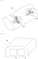
- measurement parts may be taken from different transverse cross-sections, or as shown in FIG. 6 , a plurality of measurement parts A5, A6 may be taken from the same transverse cross-section.
- resistor body inks in which the average particle size ⁇ of the metal particles was 1.3 um and the average particle size ⁇ of the ceramic particles was 0.5 um, were produced.
- the blend ratio of the metal particles was variously changed for the respective resistor body inks.
- Each resistor body ink was printed in a predetermined heat generation pattern and was dried, and then was sintered at such a temperature that the metal particles were not oxidized. Then, the electric resistivity at 25°C when the thickness was 25 um was measured by a usual method.
- the obtained result is shown in FIG. 7 .
- the content of the metal component is the area ratio (% by area) when ten different measurement parts of 10 um squares in the transverse cross-section of the heat-generation resistor body were measured as described above.
- the average content of the metal component in the present invention is set to be less than 50% by area.
- FIG. 8 shows a result of actually measuring the contents of the metal components of the heat-generation resistor bodies in Comparative examples 1, 2, 3 and Example.
- a result of measurements at ten points randomly selected in each sample is plotted on the left side in each sample, and a result of measurements for an area containing a large amount of metal component and an area containing a small amount of metal component, which were intentionally selected visually in each sample, were plotted on the right side in each sample.
- FIG. 9 shows a result of calculating the average content, the maximum content, and the minimum content of the metal component, and the max-min difference of the content of the metal component in each of Comparative examples 1, 2, 3 and Example on the basis of the measurement result shown in FIG. 8 .
Landscapes
- Chemical & Material Sciences (AREA)
- Engineering & Computer Science (AREA)
- Ceramic Engineering (AREA)
- Resistance Heating (AREA)
Abstract
Description
- The present invention relates to a ceramic heater used for, for example, a warm water washing toilet seat, a fan heater, an electric water heater, a 24-hour bath system, a soldering iron, a hair straightener, and the like, and a production method for the ceramic heater.
- Conventionally, for example, in a warm water washing toilet seat, a heat exchange unit having a container (heat exchanger) made of resin is used, and in the heat exchange unit, a ceramic heater having an elongated pipe shape is provided for warming washing water contained in a heat exchanger.
- As an example of the ceramic heater, a ceramic sheet printed with a heater wiring circuit serving as a heat-generation resistor body is wrapped around a cylindrical porcelain tube made of ceramic, and these are sintered to obtain a ceramic heater (see Patent Document 1).
- Then, water flowing in a gap between the inner wall of the heat exchanger and the outer circumference of the ceramic heater is heated by the ceramic heater.
- Patent Document 1:
Japanese Patent Application Laid-Open (kokai) No. H09-7739 - If the ceramic heater is downsized, the area of a part where heater wiring can be formed, of the ceramic sheet, is reduced. Therefore, in order to obtain the same amount of heat as in the conventional ceramic heater by one circuit, it is necessary to increase the wiring resistance, or ensure a wiring length equivalent to the conventional wiring length by reducing the wire-line width and increasing the number of times of folding.
- Here, the wiring circuit of the heater is formed by printing an ink paste containing metal particles. Therefore, in consideration of blur in printing, there is a limitation in narrowing the wire-line width (e.g., about 0.3 mm). Thus, it is necessary to increase the wiring resistance, and for this purpose, ceramic particles such as alumina are added to the ink paste.
- However, if many ceramic particles which are insulating materials are contained in wiring, ceramic particles are interposed between metal particles forming conduction paths so that conduction is hampered, thus causing a problem that disconnection becomes likely to occur.
- Accordingly, an object of the present invention is to provide a ceramic heater in which the resistance of a heat-generation resistor body is increased while disconnection is suppressed, and a production method for the ceramic heater.
- In order to solve the above problem, a ceramic heater of the present invention is a ceramic heater comprising a heat-generation resistor body embedded in a base, wherein the heat-generation resistor body includes a metal component and a ceramic component, and when ten different measurement parts of 10 um squares in a transverse cross-section of the heat-generation resistor body are measured, an average content of the metal component is not less than 35% by area but less than 50% by area, and a minimum content of the metal component is not less than 30% by area.
- With this ceramic heater, since the "average content of the metal component" which indicates the electric resistance of the entire heat-generation resistor body is set to such a level that the electric resistance increases, the resistance of the heat-generation resistor body can be increased.
- In addition, since the "minimum content of the metal component" is set to such a level that the content of the ceramic component does not vary in each measurement part, occurrence of disconnection due to local formation of such an area where there is an excessively large amount of ceramic component can be suppressed.
- Here, it is considered that, when the average content of the metal component is not less than 35% by area, the metal component aggregates and forms connection over the entirety in the heat-generation resistor body, thus stably exhibiting high conductivity.
- In the ceramic heater of the present invention, a maximum content of the metal component may be not greater than 80% by area.
- In this ceramic heater, variation in the content of the ceramic component in each measurement part described above is further reduced, so that disconnection can be further suppressed.
- In the ceramic heater of the present invention, an electric resistivity of the heat-generation resistor body per area of 100 µm2 at 25°C when a thickness thereof is 25 um mae be not less than 0.02 Ω.
- In this ceramic heater, the electric resistance of the heat-generation resistor body can be assuredly increased.
- A production method for a ceramic heater of the present invention is a production method for a ceramic heater, comprising: a ceramic base producing step of producing a ceramic base; and an application step of applying or printing an ink to be a heat-generation resistor body, around the ceramic base, wherein the ink contains metal particles and ceramic particles, an average particle size of the metal particles is 0.5 to 2.0 um, and an average particle size of the ceramic particles is 0.2 to 2.0 um.
- According to the present invention, it is possible to increase the resistance of a heat-generation resistor body of a ceramic heater while suppressing disconnection.
-
- [
FIG. 1 ] Front view showing a ceramic heater according to an embodiment of the present invention. - [
FIG. 2 ] Development view showing a ceramic sheet of the ceramic heater. - [
FIG. 3 ] Development view schematically showing heater wiring circuits included inFIG. 2 . - [
FIG. 4 ] Schematic view showing measurement parts of a heat-generation resistor body according to the embodiment of the present invention, and conduction paths in the measurement parts. - [
FIG. 5 ] Schematic view showing measurement parts of a heat-generation resistor body not corresponding to the present invention, and conduction paths in the measurement parts. - [
FIG. 6 ] View showing an example in which a plurality of measurement parts are taken from the same transverse cross-section of a heat-generation resistor body. - [
FIG. 7 ] Graph showing the actual relationship between the content of a metal component and the electric resistivity. - [
FIG. 8 ] Graph showing a result of actually measuring the contents of metal components in heat-generation resistor bodies of the ceramic heater of the present invention and commercial ceramic heaters. - [
FIG. 9 ] Table that followsFIG. 8 . - Hereinafter, an embodiment of the present invention will be described with reference to the drawings.
-
FIG. 1 is a front view showing aceramic heater 11 according to the embodiment of the present invention.FIG. 2 is a development view showing aceramic sheet 19 of theceramic heater 11.FIG. 3 is a development view schematically showingheater wiring circuits FIG. 2 . - The
ceramic heater 11 according to the embodiment of the present invention can be used for warming washing water in a heat exchanger of a heat exchange unit of a warm water washing toilet seat, for example. - As shown in
FIG. 1 , theceramic heater 11 includes a tubular base (ceramic base) 13 having a heat-generation resistor body 40 embedded therein, and aflange 30 which is joined to the outer circumference of theceramic base 13 via a joiningmember 20 and which is made of ceramic and has a ring shape, or a ring shape with ends. Theceramic base 13 includes acylindrical support body 17 made of ceramic, and aceramic sheet 19 wrapped around the outer circumference of thesupport body 17. Thesupport body 17 has a throughhole 17h in an axial-line-O direction thereof. Then, in the heat exchanger, water flowing inside the throughhole 17h is heated by theceramic heater 11 and water in the gap between the inner wall of the heat exchanger and the outer circumference of the ceramic heater is also heated by theceramic heater 11. - The
support body 17 and theceramic sheet 19 can be formed from alumina, for example. Theceramic sheet 19 does not completely cover the outer circumference of thesupport body 17, and aslit 13s extending along the axial-line-O direction of thesupport body 17 is formed at a wrap-meeting part 19a of theceramic sheet 19. - Meanwhile, as shown in
FIG. 2 , at theceramic sheet 19, a heat-generation resistor body 40 composed of a plurality ofheater wiring circuits heater wiring circuit generation resistor body 40 is formed such that foldedportions 40m at both ends of a plurality ofwiring portions 40L (see upper drawing inFIG. 3 ) mutually extending along the axial-line-O direction extend in the width direction and are connected to ends of theadjacent wiring portions 40L. The wiring portions at both ends of eachheater wiring circuit connection terminals - Specifically, as shown in
FIG. 3 , wiring portions 40L1, 40L2 at both ends of theheater wiring circuit 40a are respectively connected to theconnection terminal 41 serving as a shared ground and theconnection terminal 42a on the plus side. Similarly, wiring portions 40L3, 40L4 at both ends of theheater wiring circuit 40b are respectively connected to theconnection terminal 41 and theconnection terminal 42b on the plus side. - Then, the
connection terminals FIG. 1 ) formed at the outer circumferential surface (back surface inFIG. 2 ) of theceramic sheet 19, through via-conductors or the like (not shown). - The heat-
generation resistor body 40 and theconnection terminals - Next, with reference to
FIG. 4 andFIG. 5 , the heat-generation resistor body 40 (eachheater wiring circuit FIG. 4 is a schematic view showing measurement parts A1, A2 of the heat-generation resistor body according to the embodiment of the present invention, and conduction paths in the measurement parts A1, A2.FIG. 5 is a schematic view showing measurement parts A10, A20 of a heat-generation resistor body not corresponding to the present invention, and conduction paths in the measurement parts A10, A20. - The heat-
generation resistor body 40 contains a metal component and a ceramic component. When ten different measurement parts of 10 um squares in a transverse cross-section of the heat-generation resistor body 40 are measured, the average content of the metal component is not less than 35% by area but less than 50% by area, and the minimum content of the metal component is not less than 30% by area. - Here, as shown in
FIG. 4 , the measurement parts A1, A2 are 10-um-square areas in the transverse cross-section of the heat-generation resistor body 40 (inFIG. 4 , representing onewiring portion 40L of theheater wiring circuit 40a shown inFIG. 3 ). Then, for each measurement part A1, A2, ..., by an electron microscope (SEM), a secondary electron image (composition image) is binarized, and the area ratio (% by area) of a bright part corresponding to the metal component is calculated as the content of the metal component. - In addition, the "average content of the metal component" is the average value of the contents of the metal component in the ten measurement parts. The "minimum content of the metal component" is the smallest value of the contents of the metal component in the measurement parts. Similarly, a "maximum content of the metal component" described later is the highest value of the contents of the metal component in the measurement parts.
- Normally, the heat-
generation resistor body 40 is formed by printing an ink paste containing metal particles and ceramic particles. The ceramic particles such as alumina increases the wiring resistance, but if many ceramic particles are contained, the ceramic particles are interposed between the metal particles forming conduction paths so that conduction is hampered and disconnection becomes likely to occur. - Accordingly, as shown in
FIG. 4 , metal particles M and ceramic particles C are uniformly mixed in each measurement part A1, A2 (i.e., the content of the ceramic component does not vary in each measurement part A1, A2), whereby the metal particles M connect to each other without being separated by the ceramic particles C in each measurement part A1, A2 and thus conduction paths P are assuredly formed. - Thus, the content of the ceramic component in the heat-generation resistor body is increased so that the resistance is increased, while disconnection can be suppressed. In particular, if the wire-line width of the heat-generation resistor body 40 (
wiring portion 40L) becomes smaller, disconnection is more likely to occur when there is a part where many ceramic particles are contained locally, but such disconnection can also be suppressed. - In
FIG. 4 , for convenience sake, conduction paths P along the cross-sections of the measurement parts A1, A2 are shown, but in actuality, conduction paths are formed so as to pass the cross-section of each measurement part A1, A2 toward the backward direction of the drawing sheet. However, it is considered that the arrangement state of the metal particles M and the ceramic particles C is three-dimensionally isotropic (the arrangement states in the cross-section of each measurement part A1, A2 and in the backward direction of the drawing sheet perpendicular to the cross-section are the same). Therefore, for convenience in illustration in the drawing, conduction paths P along the cross-sections of the measurement parts A1, A2 are shown. - On the other hand, as shown in
FIG. 5 , a case where metal particles M and ceramic particles C are not uniformly mixed in each measurement part A1, A2 (i.e., the content of the ceramic component greatly varies in each measurement part A1, A2) will be considered. - In this case, in a measurement part A10, the ratio of the ceramic particles C is great (there are four particles in the measurement part) and therefore the metal particles M are separated by the ceramic particles C, so that a conduction path is not formed and disconnection B occurs. Meanwhile, in a measurement part A20, the ratio of the ceramic particles C is small (there is one particle in the measurement part) and therefore the metal particles M connect to each other without being separated by the ceramic particles C, so that a conduction path P is formed.
- From the above, as an index indicating the electric resistance of the entire heat-generation resistor body, the "average content of the metal component" described above is defined, and is set so as to increase the electric resistance.
- In addition, as an index for ensuring that the content of the ceramic component in each measurement part does not vary and occurrence of disconnection due to local formation of such an area where there is an excessively large amount of ceramic component is suppressed, the "minimum content of the metal component" described above is defined, to suppress disconnection. For example, in the measurement part A10 in
FIG. 5 , the "minimum content of the metal component" is smaller than the prescribed range of the present invention. - In the present invention, if the maximum content of the metal component is not greater than 80% by area, variation in the content of the ceramic component in each measurement part described above is further reduced, so that disconnection can be further suppressed.
- In the present invention, if the electric resistivity of the heat-
generation resistor body 40 per area of 100 µm2 at 25°C when the thickness thereof is 25 um is not less than 0.02 Ω, the electric resistance of the heat-generation resistor body can be assuredly increased. For the electric resistivity, the heat-generation resistor body 40 is cut and the resistance is measured, the width, the thickness, and the length of the cut part are measured, and then the resistance value per area of 100 µm2 when the thickness is 25 um is calculated. - In the present embodiment, as a method for controlling the average content of the metal component and the minimum content of the metal component in the above ranges, for example, the particle sizes of the metal particles and the ceramic particles contained in a resistor body ink for forming the heat-
generation resistor body 40 are made fine. By making the particle sizes of the respective particles fine, the degree of dispersion when the respective particles are mixed is increased, whereby variation in the content of the ceramic component can be reduced. - Specifically, for example, in a case of performing measurement using a particle size distribution by laser diffraction and scattering, an average particle size ϕ of the metal particles can be set at 0.5 to 2.0 um, and an average particle size ϕ of the ceramic particles can be set at 0.2 to 2.0 um.
- As the metal particles, tungsten powder and molybdenum powder can be used in combination. Examples of the ceramic particles include alumina.
- By adjusting the sintering temperature for forming the heat-
generation resistor body 40, in particular, by suppressing excessive grain growth or excessive sintering of the metal component, variation in the content of the ceramic component can be reduced. - The resistor body ink can be produced as follows, for example. First, the metal particles and the ceramic particles are weighed and put into a pot, and a solvent is further added. Then, the particles are crushed into fine powder by a ball mill. Further, resin (binder) is added into the ball mill, to be further mixed and crushed. Thereafter, the extra solvent is removed through exposure to air. Thus, a slurry ink is obtained.
- The
ceramic heater 11 can be produced as follows, for example. - First, from slurry of ceramic powder such as alumina, a member to be the
support body 17 is extrusion-molded, and then is calcined. In addition, from the same slurry as above, a green sheet to be theceramic sheet 19 is formed, and on the surface thereof, the above resistor body ink to be the heat-generation resistor body 40 and theconnection terminals FIG. 2 is printed and dried. Then, on the printed surface of the green sheet, another green sheet is laminated and pressed, whereby the heat-generation resistor body 40 and theconnection terminals external terminals 43 are printed and dried. - Then, a ceramic paste is applied on the opposite surface of the laminated body of both green sheets, the laminated body is wrapped around the
support body 17, and the entire body is sintered. - In addition, ceramic powder such as alumina is pressure-molded by a mold and then sintered, thus obtaining the
flange 30. - The
ceramic base 13 and theflange 30 produced as described above are heated at a glass melting temperature or higher in a state in which a solid joining material 20 (glass) to be the joiningmember 20 is placed in a gap between theceramic base 13 and theflange 30, whereby theflange 30 is joined to the outer circumference of theceramic base 13. - The production method for the ceramic heater of the present invention includes a ceramic base producing step of producing a ceramic base, and an application step of applying (printing) an ink to be a heat-generation resistor body, around the ceramic base. The above ink contains metal particles and ceramic particles, an average particle size of the metal particles is 0.5 to 2.0 um, and an average particle size of the ceramic particles is 0.2 to 2.0 µm.
- It should be understood that the present invention is not limited to the above embodiment and incorporates various modifications and equivalents within the idea and the scope of the present invention.
- The kinds of the metal component and the ceramic component composing the heat-generation resistor body are not limited to the above ones.
- The number of heater wiring circuits and the shape thereof are also not limited.
- Regarding each measurement part in a transverse cross-section of the heat-generation resistor body, measurement parts may be taken from different transverse cross-sections, or as shown in
FIG. 6 , a plurality of measurement parts A5, A6 may be taken from the same transverse cross-section. - Using tungsten powder and molybdenum powder as metal particles and using alumina powder as ceramic particles, resistor body inks in which the average particle size ϕ of the metal particles was 1.3 um and the average particle size ϕ of the ceramic particles was 0.5 um, were produced. The blend ratio of the metal particles was variously changed for the respective resistor body inks.
- Each resistor body ink was printed in a predetermined heat generation pattern and was dried, and then was sintered at such a temperature that the metal particles were not oxidized. Then, the electric resistivity at 25°C when the thickness was 25 um was measured by a usual method.
- The obtained result is shown in
FIG. 7 . The content of the metal component is the area ratio (% by area) when ten different measurement parts of 10 um squares in the transverse cross-section of the heat-generation resistor body were measured as described above. - As shown in
FIG. 7 , when the content of the metal component is less than approximately 50% by area, the electric resistivity sharply increases. On the basis of this result, the average content of the metal component in the present invention is set to be less than 50% by area. - For a ceramic heater (Example) produced in the same manner as in Example 1 and commercial ceramic heaters (Comparative examples 1 to 3), the "average content of the metal component", the "minimum content of the metal component", and the "maximum content of the metal component" were measured by the above method. In addition, a max-min difference of the content of the metal component = (maximum content of metal component) - (minimum content of metal component) was calculated.
- The obtained results are shown in
FIG. 8 andFIG. 9 . -
FIG. 8 shows a result of actually measuring the contents of the metal components of the heat-generation resistor bodies in Comparative examples 1, 2, 3 and Example. A result of measurements at ten points randomly selected in each sample is plotted on the left side in each sample, and a result of measurements for an area containing a large amount of metal component and an area containing a small amount of metal component, which were intentionally selected visually in each sample, were plotted on the right side in each sample. -
FIG. 9 shows a result of calculating the average content, the maximum content, and the minimum content of the metal component, and the max-min difference of the content of the metal component in each of Comparative examples 1, 2, 3 and Example on the basis of the measurement result shown inFIG. 8 . - In Comparative examples 1, 2, the "average contents of the metal components" were not less than 50% by area and therefore were greater than that in Example. Thus, the resistances of the heat-generation resistor bodies of the ceramic heaters could not be increased.
- In Comparative example 3, the "average content of the metal component" was great equivalently to that in Example, but the "minimum content of the metal component" was less than 30% by area and therefore less than that in Example. Thus, it is considered that disconnection is likely to occur.
-
- 11 ceramic heater
- 40 heat-generation resistor body
- A1,A2,A5,A6 measurement part
Claims (4)
- A ceramic heater comprising a heat-generation resistor body embedded in a base, whereinthe heat-generation resistor body includes a metal component and a ceramic component, andwhen ten different measurement parts of 10 um squares in a transverse cross-section of the heat-generation resistor body are measured, an average content of the metal component is not less than 35% by area but less than 50% by area, and a minimum content of the metal component is not less than 30% by area.
- The ceramic heater according to claim 1, wherein
a maximum content of the metal component is not greater than 80% by area. - The ceramic heater according to claim 1 or 2, wherein
an electric resistivity of the heat-generation resistor body per area of 100 µm2 at 25°C when a thickness thereof is 25 um is not less than 0.02 Ω. - A production method for a ceramic heater, comprising:a ceramic base producing step of producing a ceramic base; andan application step of applying or printing an ink to be a heat-generation resistor body, around the ceramic base, whereinthe ink contains metal particles and ceramic particles, an average particle size of the metal particles is 0.5 to 2.0 um, and an average particle size of the ceramic particles is 0.2 to 2.0 um.
Applications Claiming Priority (2)
| Application Number | Priority Date | Filing Date | Title |
|---|---|---|---|
| JP2021065623 | 2021-04-08 | ||
| PCT/JP2022/017033 WO2022215676A1 (en) | 2021-04-08 | 2022-04-04 | Ceramic heater, and method for manufacturing ceramic heater |
Publications (2)
| Publication Number | Publication Date |
|---|---|
| EP4322707A1 true EP4322707A1 (en) | 2024-02-14 |
| EP4322707A4 EP4322707A4 (en) | 2025-04-09 |
Family
ID=83546086
Family Applications (1)
| Application Number | Title | Priority Date | Filing Date |
|---|---|---|---|
| EP22784659.9A Pending EP4322707A4 (en) | 2021-04-08 | 2022-04-04 | CERAMIC HEATING ELEMENT AND METHOD FOR PRODUCING A CERAMIC HEATING ELEMENT |
Country Status (4)
| Country | Link |
|---|---|
| EP (1) | EP4322707A4 (en) |
| JP (1) | JPWO2022215676A1 (en) |
| CN (1) | CN116868684A (en) |
| WO (1) | WO2022215676A1 (en) |
Family Cites Families (12)
| Publication number | Priority date | Publication date | Assignee | Title |
|---|---|---|---|---|
| JP3110974B2 (en) * | 1995-05-16 | 2000-11-20 | 日本特殊陶業株式会社 | Alumina ceramic heater with metallized heating layer |
| JP3493247B2 (en) * | 1995-06-21 | 2004-02-03 | 京セラ株式会社 | Ceramic heater |
| JP3691649B2 (en) * | 1997-10-28 | 2005-09-07 | 日本特殊陶業株式会社 | Ceramic heater |
| JP2005340034A (en) * | 2004-05-27 | 2005-12-08 | Kyocera Corp | Ceramic heater, method for manufacturing the same, and heating iron |
| KR20080108372A (en) * | 2003-12-24 | 2008-12-12 | 쿄세라 코포레이션 | Ceramic heater and its manufacturing method |
| JP4596790B2 (en) * | 2004-02-23 | 2010-12-15 | 京セラ株式会社 | Ceramic heater and wafer support member using the same |
| DE102008041433A1 (en) * | 2007-08-23 | 2009-02-26 | Denso Corp., Kariya-shi | Ceramic heating device for use in gas sensor, has heating unit abutting at substrate with its entire circumference without forming space between unit and substrate, where unit is manufactured from electrically conducting material |
| JP5258480B2 (en) * | 2008-09-26 | 2013-08-07 | 京セラ株式会社 | Ceramic heater |
| US10480786B2 (en) * | 2012-06-29 | 2019-11-19 | Kyocera Corporation | Heater and glow plug including the same |
| JP6604884B2 (en) * | 2016-03-30 | 2019-11-13 | 日本特殊陶業株式会社 | Ceramic heater |
| EP3522681B1 (en) * | 2018-02-05 | 2022-06-08 | Ngk Spark Plug Co., Ltd. | Ceramic heater |
| JP6924729B2 (en) * | 2018-02-05 | 2021-08-25 | 日本特殊陶業株式会社 | Ceramic heater |
-
2022
- 2022-04-04 CN CN202280016310.5A patent/CN116868684A/en active Pending
- 2022-04-04 JP JP2022560471A patent/JPWO2022215676A1/ja active Pending
- 2022-04-04 EP EP22784659.9A patent/EP4322707A4/en active Pending
- 2022-04-04 WO PCT/JP2022/017033 patent/WO2022215676A1/en not_active Ceased
Also Published As
| Publication number | Publication date |
|---|---|
| EP4322707A4 (en) | 2025-04-09 |
| WO2022215676A1 (en) | 2022-10-13 |
| JPWO2022215676A1 (en) | 2022-10-13 |
| CN116868684A (en) | 2023-10-10 |
Similar Documents
| Publication | Publication Date | Title |
|---|---|---|
| CN107871542B (en) | Silver Paste and Electronic Components | |
| JP4934993B2 (en) | Conductive paste and wiring board using the same | |
| TW201734218A (en) | Silver powder, silver paste, and use therefor | |
| EP1199908A1 (en) | Ceramic heater | |
| CN107205288B (en) | Heating device with support and method for producing the same | |
| CN109478572B (en) | Process for producing highly conductive printable pastes from capillary suspensions | |
| CN112292738B (en) | Ceramic multilayer component and method for producing a ceramic multilayer component | |
| EP0300685A2 (en) | Improvements in or relating to thick film track material | |
| KR20190022296A (en) | Thick film resistor composition and thick film resistor paste comprising the same | |
| KR101777690B1 (en) | Heating composition, ceramic heater and fusing belt using the same | |
| JP2013136818A (en) | Copper powder | |
| JP2019053856A (en) | Silver paste | |
| JP5458862B2 (en) | Heat-curable silver paste and conductor film formed using the same | |
| WO2022215676A1 (en) | Ceramic heater, and method for manufacturing ceramic heater | |
| CN105895258B (en) | A kind of preparation method of multilayer co-firing silver paste of inner electrode | |
| JP6331936B2 (en) | Copper-nickel thick film resistor and manufacturing method thereof | |
| US8384751B2 (en) | Thermal head | |
| JP6818886B2 (en) | heater | |
| WO1999063553A1 (en) | Thick film resistor compositions for making heat-transfer tapes and use thereof | |
| CN110121222B (en) | Ceramic heater | |
| JP5662361B2 (en) | Resistor paste for ceramic substrate heater and ceramic substrate heater | |
| JP2004055345A (en) | Conductive paste for forming fine circuits | |
| EP0829885A1 (en) | Thick film resistor | |
| DE102017112611A1 (en) | Infrared radiator and method for its manufacture | |
| JP6709677B2 (en) | Method for preparing high-conductivity thick-film aluminum paste |
Legal Events
| Date | Code | Title | Description |
|---|---|---|---|
| STAA | Information on the status of an ep patent application or granted ep patent |
Free format text: STATUS: THE INTERNATIONAL PUBLICATION HAS BEEN MADE |
|
| PUAI | Public reference made under article 153(3) epc to a published international application that has entered the european phase |
Free format text: ORIGINAL CODE: 0009012 |
|
| STAA | Information on the status of an ep patent application or granted ep patent |
Free format text: STATUS: REQUEST FOR EXAMINATION WAS MADE |
|
| 17P | Request for examination filed |
Effective date: 20230906 |
|
| AK | Designated contracting states |
Kind code of ref document: A1 Designated state(s): AL AT BE BG CH CY CZ DE DK EE ES FI FR GB GR HR HU IE IS IT LI LT LU LV MC MK MT NL NO PL PT RO RS SE SI SK SM TR |
|
| DAV | Request for validation of the european patent (deleted) | ||
| DAX | Request for extension of the european patent (deleted) | ||
| A4 | Supplementary search report drawn up and despatched |
Effective date: 20250312 |
|
| RIC1 | Information provided on ipc code assigned before grant |
Ipc: H05B 3/48 20060101ALI20250306BHEP Ipc: H05B 3/18 20060101ALI20250306BHEP Ipc: H05B 3/12 20060101AFI20250306BHEP |