EP4321915A2 - Virtual or augmented reality headsets having adjustable interpupillary distance - Google Patents
Virtual or augmented reality headsets having adjustable interpupillary distance Download PDFInfo
- Publication number
- EP4321915A2 EP4321915A2 EP23201335.9A EP23201335A EP4321915A2 EP 4321915 A2 EP4321915 A2 EP 4321915A2 EP 23201335 A EP23201335 A EP 23201335A EP 4321915 A2 EP4321915 A2 EP 4321915A2
- Authority
- EP
- European Patent Office
- Prior art keywords
- virtual
- augmented reality
- headset
- eyepieces
- frame
- Prior art date
- Legal status (The legal status is an assumption and is not a legal conclusion. Google has not performed a legal analysis and makes no representation as to the accuracy of the status listed.)
- Pending
Links
Images









Classifications
-
- G—PHYSICS
- G02—OPTICS
- G02B—OPTICAL ELEMENTS, SYSTEMS OR APPARATUS
- G02B27/00—Optical systems or apparatus not provided for by any of the groups G02B1/00 - G02B26/00, G02B30/00
- G02B27/01—Head-up displays
- G02B27/017—Head mounted
- G02B27/0176—Head mounted characterised by mechanical features
-
- G—PHYSICS
- G02—OPTICS
- G02B—OPTICAL ELEMENTS, SYSTEMS OR APPARATUS
- G02B27/00—Optical systems or apparatus not provided for by any of the groups G02B1/00 - G02B26/00, G02B30/00
- G02B27/01—Head-up displays
- G02B27/017—Head mounted
- G02B27/0172—Head mounted characterised by optical features
-
- G—PHYSICS
- G02—OPTICS
- G02B—OPTICAL ELEMENTS, SYSTEMS OR APPARATUS
- G02B27/00—Optical systems or apparatus not provided for by any of the groups G02B1/00 - G02B26/00, G02B30/00
- G02B27/01—Head-up displays
- G02B27/0179—Display position adjusting means not related to the information to be displayed
-
- G—PHYSICS
- G02—OPTICS
- G02B—OPTICAL ELEMENTS, SYSTEMS OR APPARATUS
- G02B7/00—Mountings, adjusting means, or light-tight connections, for optical elements
- G02B7/02—Mountings, adjusting means, or light-tight connections, for optical elements for lenses
- G02B7/12—Adjusting pupillary distance of binocular pairs
-
- G—PHYSICS
- G02—OPTICS
- G02C—SPECTACLES; SUNGLASSES OR GOGGLES INSOFAR AS THEY HAVE THE SAME FEATURES AS SPECTACLES; CONTACT LENSES
- G02C5/00—Constructions of non-optical parts
- G02C5/02—Bridges; Browbars; Intermediate bars
- G02C5/04—Bridges; Browbars; Intermediate bars with adjustable means
-
- G—PHYSICS
- G02—OPTICS
- G02C—SPECTACLES; SUNGLASSES OR GOGGLES INSOFAR AS THEY HAVE THE SAME FEATURES AS SPECTACLES; CONTACT LENSES
- G02C5/00—Constructions of non-optical parts
- G02C5/02—Bridges; Browbars; Intermediate bars
- G02C5/04—Bridges; Browbars; Intermediate bars with adjustable means
- G02C5/045—Bridges; Browbars; Intermediate bars with adjustable means for varying the horizontal distance of the lenses
-
- G—PHYSICS
- G02—OPTICS
- G02C—SPECTACLES; SUNGLASSES OR GOGGLES INSOFAR AS THEY HAVE THE SAME FEATURES AS SPECTACLES; CONTACT LENSES
- G02C5/00—Constructions of non-optical parts
- G02C5/02—Bridges; Browbars; Intermediate bars
- G02C5/08—Bridges; Browbars; Intermediate bars foldable
-
- G—PHYSICS
- G06—COMPUTING OR CALCULATING; COUNTING
- G06T—IMAGE DATA PROCESSING OR GENERATION, IN GENERAL
- G06T19/00—Manipulating three-dimensional [3D] models or images for computer graphics
- G06T19/006—Mixed reality
-
- G—PHYSICS
- G02—OPTICS
- G02B—OPTICAL ELEMENTS, SYSTEMS OR APPARATUS
- G02B27/00—Optical systems or apparatus not provided for by any of the groups G02B1/00 - G02B26/00, G02B30/00
- G02B27/01—Head-up displays
- G02B27/0149—Head-up displays characterised by mechanical features
- G02B2027/0154—Head-up displays characterised by mechanical features with movable elements
-
- G—PHYSICS
- G02—OPTICS
- G02B—OPTICAL ELEMENTS, SYSTEMS OR APPARATUS
- G02B27/00—Optical systems or apparatus not provided for by any of the groups G02B1/00 - G02B26/00, G02B30/00
- G02B27/01—Head-up displays
- G02B27/0149—Head-up displays characterised by mechanical features
- G02B2027/0169—Supporting or connecting means other than the external walls
-
- G—PHYSICS
- G02—OPTICS
- G02B—OPTICAL ELEMENTS, SYSTEMS OR APPARATUS
- G02B27/00—Optical systems or apparatus not provided for by any of the groups G02B1/00 - G02B26/00, G02B30/00
- G02B27/01—Head-up displays
- G02B27/017—Head mounted
- G02B2027/0178—Eyeglass type
-
- G—PHYSICS
- G02—OPTICS
- G02B—OPTICAL ELEMENTS, SYSTEMS OR APPARATUS
- G02B27/00—Optical systems or apparatus not provided for by any of the groups G02B1/00 - G02B26/00, G02B30/00
- G02B27/01—Head-up displays
- G02B27/0179—Display position adjusting means not related to the information to be displayed
- G02B2027/0181—Adaptation to the pilot/driver
Definitions
- This disclosure generally relates to virtual or augmented reality headsets, and more particularly to virtual or augmented reality headsets wherein the interpupillary distance of the eyepieces is adjustable.
- Virtual or augmented reality headsets have long been proven invaluable for many applications, spanning the fields of scientific visualization, medicine and military training, engineering design and prototyping, tele-manipulation and tele-presence, and personal entertainment systems.
- virtual reality systems computer-generated virtual scenes are generally provided on an opaque display.
- mixed and augmented reality systems computer-generated virtual scenes or objects are combined with the views of a real-world scene on a see-through display.
- virtual or augmented reality headsets virtual or augmented scenes are displayed on separate eyepieces. The interpupillary distance between the optical centers of such eyepieces are often fixed, and corrections that may be needed to adjust for variations in users having different interpupillary distances is made via software to provide corrective display adjustments.
- the interpupillary distance between the optical centers of eyepieces may be mechanically adjustable; however, in such instances, adjustment devices can suffer from various drawbacks.
- the adjustment mechanisms may be overly complex, bulky, lack precision and/or include a limited range of motion.
- Embodiments described herein provide virtual or augmented reality headsets with robust and efficient form factors that enable simultaneous movement of viewer eyepieces along one or more linear rails to provide interpupillary distance adjustment.
- a virtual or augmented reality headset may be summarized as including a frame, a pair of virtual or augmented reality eyepieces, and an adjustment mechanism coupled to both of the pair of virtual or augmented reality eyepieces.
- the frame may include opposing arm members, a bridge positioned intermediate the opposing arm members, and a plurality of linear rails. At least one linear rail may be provided at each of opposing sides of the frame defined by a central reference plane.
- the pair of virtual or augmented reality eyepieces each have an optical center and may be movably coupled to the plurality of linear rails of the frame to enable adjustment of an interpupillary distance between the optical centers.
- the adjustment mechanism may be operable to simultaneously move the pair of virtual or augmented reality eyepieces in adjustment directions aligned with the plurality of linear rails to adjust the interpupillary distance.
- the virtual or augmented reality eyepieces may be movable between a narrowest configuration and a widest configuration, and a difference between the interpupillary distance in the widest configuration and the interpupillary distance in the narrowest configuration may be between about 20 mm and about 24 mm.
- the adjustment mechanism may be coupled to the bridge of the frame and may include a manipulable actuator coupled to the virtual or augmented reality eyepieces for selectively adjusting a linear position of each of the virtual or augmented reality eyepieces simultaneously.
- the frame may further include a lock to selectively fix the virtual or augmented reality eyepieces in a selected linear position along the plurality of linear rails.
- the adjustment mechanism may include a manipulable actuator manually operable by a user and one or more links physically may couple the manipulable actuator to the virtual or augmented reality eyepieces.
- the headset may further include a selectively removable cover that is selectively positionable to alternatively prevent access to the manipulable actuator and to provide access to the manipulable actuator by the user.
- the manipulable actuator may be constrained to translate back and forth in directions perpendicular to the adjustment directions aligned with the plurality of linear rails, and movement of the manipulable actuator in one direction may move the virtual or augmented reality eyepieces toward an expanded configuration while movement of the manipulable actuator in the opposite direction may move the virtual or augmented reality eyepieces toward a collapsed configuration.
- the manipulable actuator may be accessible to the user while the headset is worn.
- the adjustment mechanism may include one or more linear actuators, such as, for example, a piezoelectric linear actuator or a motor-driven lead screw.
- the bridge of the frame may include a nosepiece to engage a nose of the user and support the virtual or augmented reality eyepieces in front of the user's eyes.
- the nosepiece may be removably coupleable to a base portion of the bridge to selectively lock the virtual or augmented reality eyepieces in a selected position.
- Each virtual or augmented reality eyepiece may be arcuate and may include a medial end and a lateral end.
- the medial end may be positioned proximate the bridge of the frame and the lateral end may be positioned proximate a temple region of a respective one of the opposing arm members.
- the frame may include a respective arcuate profile on each of opposing sides of the central reference plane to at least partially nest with a respective one of the virtual or augmented reality eyepieces when the virtual or augmented reality eyepieces are in a narrowest configuration in which the interpupillary distance is at a minimum.
- the plurality of linear rails may include at least two linear rails on each of opposing sides of the frame to guide a respective one of the virtual or augmented reality eyepieces, and wherein, for each of the opposing sides of the frame, a first one of the linear rails may be located proximate the bridge to guide the medial end of the respective virtual or augmented reality eyepiece and a second one of the linear rails may be located proximate the temple region to guide the lateral end of the respective virtual or augmented reality eyepiece.
- Each of the virtual or augmented reality eyepieces may be coupled to at least two linear rails that are offset fore and aft from each other.
- the plurality of linear rails of the frame may include at least two linear rails on each of opposing sides of the frame to guide a respective one of the virtual or augmented reality eyepieces, and wherein, for each of the opposing sides of the frame, the two linear rails may be located proximate the bridge to guide a medial end of the respective virtual or augmented reality eyepiece and support the respective virtual or augmented reality eyepiece in a cantilevered manner.
- the plurality of linear rails of the frame may include at least two linear rails on each of opposing sides of the frame vertically offset from each other to guide a respective one of the virtual or augmented reality eyepieces.
- the at least two linear rails and the arm member may form a fork structure.
- the two linear rails and a portion of the bridge may form a fork structure that supports the respective one of the virtual or augmented reality eyepieces.
- Each of the virtual or augmented reality eyepieces may be supported by a single respective linear rail underlying the eyepiece and supported in space only by a connection to the single respective linear rail.
- each of the virtual or augmented reality eyepieces may be supported by a single respective linear rail positioned above a horizontal plane defined by the optical centers of the pair of virtual or augmented reality eyepieces and supported in space only by a connection to the single respective linear rail.
- the bridge and the plurality of rails of the frame may be integrally formed as a single-piece.
- the bridge, the opposing arm members and the plurality of rails of the frame may be integrally formed as a single-piece.
- the frame may further include a central frame portion comprising the bridge, and the opposing arm members may be hingedly connected to the central frame portion.
- the invention can also be directed to the following items:
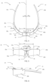
- FIGS 1 through 6 show one example embodiment of a virtual or augmented reality headset 10.
- the headset 10 includes a frame 12 and a pair of virtual or augmented reality eyepieces 30a, 30b supported by the frame 12.
- the frame 12 has opposing arm members 14a, 14b, a bridge 16 positioned intermediate the opposing arm members 14a, 14b, and a plurality of linear rails 18a, 18b, 20a, 20b. More particularly, two linear rails 18a, 18b, 20a, 20b are provided at each of opposing sides 22, 24 of the frame 12 defined by a central reference plane 26.
- the pair of virtual or augmented reality eyepieces 30a, 30b each has an optical center 32a, 32b, a distance between which defines an interpupillary distance IPD.
- the eyepieces 30a, 30b are movably coupled to the plurality of linear rails 18a, 18b, 20a, 20b to enable adjustment of the interpupillary distance IPD as desired to correspond to or more closely correspond to an actual interpupillary distance between the pupils of a wearer.
- the headset 10 further includes an adjustment mechanism 34 coupled to both of the pair of virtual or augmented reality eyepieces 30a, 30b.
- the adjustment mechanism 34 is operable to simultaneously move the eyepieces 30a, 30b in adjustment directions 42, 44 aligned with the linear rails 18a, 18b, 20a, 20b to adjust the interpupillary distance IPD.
- the virtual or augmented reality eyepieces 30a, 30b are movable between a fully collapsed or narrowest configuration ( Figures 1 , 2 and 4-6 ) and a fully expanded or widest configuration ( Figure 3 ).
- each individual eyepiece 30a, 30b may be adjusted a distance between about 10 mm and 12 mm. It is appreciated, however, that in some embodiments, more or less adjustment may be provided.
- a nosepiece 36 may be provided at the bridge 16 of the frame 12 to engage a nose of the user and support the virtual or augmented reality eyepieces 30a, 30b in front of the user's eyes during use.
- the nosepiece 36 may be integrally formed as a portion of the bridge 16, fixedly secured to the bridge 16, or removably coupled to the bridge 16.
- the nosepiece 36 may be removably coupleable to a base portion of the bridge 16 and impede the travel of the adjustment mechanism 34 to lock the virtual or augmented reality eyepieces 30a, 30b in a selected position.
- a lock may be provided on each eyepiece 30a, 30b, to clamp to a respective one of the linear rails 18a, 18b, 20a, 20b, or vice versa.
- a user may selectively unlock the eyepieces 30a, 30b for adjustment, adjust the eyepieces 30a, 30b transversely to a new interpupillary distance IPD, and lock the eyepieces 30a, 30b in place at the new interpupillary distance IPD.
- the lock may include, for example, one or more clamps, set screws, clips or other fasteners to impede movement of the adjustment mechanism 34 and/or eyepieces 30a, 30b, or otherwise lock the same.
- the lock may be spring-biased toward a locked position.
- each virtual or augmented reality eyepiece 30a, 30b may be arcuate and include a medial end and a lateral end.
- the medial end may be positioned proximate the bridge 16 of the frame 12 and the lateral end may be positioned proximate a temple region of a respective one of the opposing arm members 14a, 14b.
- the frame 12 may include a respective arcuate profile on each of opposing sides 22, 24 of the central reference plane 26 to at least partially nest with a respective one of the virtual or augmented reality eyepieces 30a, 30b when the virtual or augmented reality eyepieces 30a, 30b are in the fully collapsed or narrowest configuration ( Figures 1 , 2 and 5-6 ) in which the interpupillary distance IPD is at a minimum.
- the headset 10 may include a pair of linear rails 18a, 20a and 18b, 20b on each of opposing sides 22, 24 of the frame 12 to guide a respective one of the virtual or augmented reality eyepieces 30a, 30b.
- a first one of the linear rails 18a, 18b may be located proximate the bridge 16 to guide the medial end of the respective virtual or augmented reality eyepiece 30a, 30b and a second one of the linear rails 20a, 20b may be located proximate the temple region to guide the lateral end of the respective virtual or augmented reality eyepiece 30a, 30b.
- each of the virtual or augmented reality eyepieces 30a, 30b may be coupled to at least two linear rails 18a, 20a and 18b, 20b that are offset fore and aft from each other.
- the linear rails may be protruding rods or telescoping elements that project from a side of the frame 12.
- the rails 18a, 18b, 20a, 20b may be substantially or completely concealed from view when in the fully collapsed or narrowest configuration and/or when in the fully expanded or widest configuration.
- the eyepieces 30a, 30b may be generally arc-shaped and may move transversely along the linear rails 18a, 18b, 20a, 20b between an extreme medial position nearer the central plane 26 and an extreme lateral position farther from the central plane 26.
- the eyepieces 30a, 30b may be located at any position between the extreme end positions and secured in place with a lock or other fastening mechanism or fixation method.
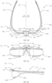
- FIGS 7 through 12 show another example embodiment of a virtual or augmented reality headset 110.
- the headset 110 includes a frame 112 and a pair of virtual or augmented reality eyepieces 130a, 130b supported by the frame 112.
- the frame 112 has opposing arm members 114a, 114b, a bridge 116 positioned intermediate the opposing arm members 114a, 114b, and a plurality of linear rails 118a, 118b, 120a, 120b. More particularly, two linear rails 118a, 118b, 120a, 120b are provided at each of opposing sides 122, 124 of the frame 112 defined by a central reference plane 126.
- the linear rails 118a, 118b, 120a, 120b may transition to curvilinear rails or rail portions beyond the range of adjustability range of the eyepieces 130a, 130b.
- the pair of virtual or augmented reality eyepieces 130a, 130b each have an optical center 132a, 132b, a distance between which defines an interpupillary distance IPD.
- the eyepieces 130a, 130b are movably coupled to the plurality of linear rails 118a, 118b, 120a, 120b to enable adjustment of the interpupillary distance IPD as desired to correspond to or more closely correspond to an actual interpupillary distance between the pupils of a wearer.
- the headset 110 further includes an adjustment mechanism 134 coupled to both of the pair of virtual or augmented reality eyepieces 130a, 130b.
- the adjustment mechanism 134 is operable to simultaneously move the eyepieces 130a, 130b in adjustment directions 142, 144 aligned with the linear rails 118a, 118b, 120a, 120b to adjust the interpupillary distance IPD.
- the virtual or augmented reality eyepieces 130a, 130b are movable between a fully collapsed or narrowest configuration ( Figures 7 , 8 and 10-12 ) and a fully expanded or widest configuration ( Figure 9 ).
- the frame 112, eyepieces 130a, 130b, and rails 118a, 118b, 120a, 120b are configured relative to each other such that a difference between the interpupillary distance IPD in the fully expanded or widest configuration and the interpupillary distance IPD in the fully collapsed or narrowest configuration is between about 20 mm and about 24 mm.
- each individual eyepiece 130a, 130b may be adjusted a distance between about 10 mm and 12 mm. It is appreciated, however, that in some embodiments, more or less adjustment may be provided.
- a nosepiece 136 may be provided at the bridge 116 of the frame 112 to engage a nose of the user and support the virtual or augmented reality eyepieces 130a, 130b in front of the user's eyes during use.
- the nosepiece 136 may be integrally formed as a portion of the bridge 116, fixedly secured to the bridge 116, or removably coupled to the bridge 116.
- the nosepiece 136 may be removably coupleable to a base portion of the bridge 116 and impede the travel of the adjustment mechanism 134 to lock the virtual or augmented reality eyepieces 130a, 130b in a selected position.
- a lock may be provided on each eyepiece 130a, 130b, to clamp to a respective one of the linear rails 118a, 118b, 120a, 120b, or vice versa.
- a user may selectively unlock the eyepieces 130a, 130b for adjustment, adjust the eyepieces 130a, 130b transversely to a new interpupillary distance IPD, and lock the eyepieces 130a, 130b in place at the new interpupillary distance IPD.
- the lock may include, for example, one or more clamps, set screws, clips or other fasteners to impede movement of the adjustment mechanism 134 and/or eyepieces 130a, 130b, or otherwise fix the same in place.
- the lock may be spring-biased toward a locked position.
- each virtual or augmented reality eyepiece 130a, 130b may be arcuate and include a medial end and a lateral end.
- the medial end may be positioned proximate the bridge 116 of the frame 112 and the lateral end may be positioned proximate a temple region of a respective one of the opposing arm members 114a, 114b.
- the frame 112 may include a respective arcuate profile on each of opposing sides 122, 124 of the central reference plane 126 that generally reflects that of the respective virtual or augmented reality eyepieces 130a, 130b.
- the headset 110 may include a pair of linear rails 118a, 120a and 118b, 120b on each of opposing sides 122, 124 of the frame 112 to guide a respective one of the virtual or augmented reality eyepieces 130a, 130b.
- a first one of the linear rails 118a, 118b may be located proximate the bridge 116 at an upper region of the headset 110 to guide an upper portion of the medial end of the respective virtual or augmented reality eyepiece 130a, 130b and a second one of the linear rails 120a, 120b may be located proximate the bridge 116 at a lower region of the headset 110 to guide a lower portion of the medial end of the respective virtual or augmented reality eyepiece 130a, 130b.
- At least two linear rails 118a, 120a and 118b, 120b may be provided on each of opposing sides 122, 124 of the frame 112 to guide a respective one of the virtual or augmented reality eyepieces 130a, 130b.
- the two linear rails 118a, 120a and 118b, 120b on each side 122, 124 may be located proximate the bridge 16 to guide the medial end of the respective virtual or augmented reality eyepiece 130a, 130b and support the eyepiece in a cantilevered manner.
- the two linear rails 118a, 120a and 118b, 120b on each of opposing sides 122, 124 of the frame 112 may be vertically offset from each other and may form a fork structure with a respective arm member 114a, 114b of the frame 112.
- the eyepieces 130a, 130b may be received within the tines of the fork structure.
- the two linear rails 118a, 120a and 118b, 120b on each of opposing sides 122, 124 of the frame 112 and a portion of the bridge 116 may form a fork structure oriented away from the central plane 126 to support the eyepieces 130a, 130b.
- the eyepieces 130a, 130b may be generally arc-shaped and may move transversely along the linear rails 118a, 118b, 120a, 120b between an extreme medial position nearer the central plane 126 and an extreme lateral position farther from the central plane 126.
- the eyepieces 130a, 130b may be located at any position between the extreme end positions and secured in place with a lock or other fastening mechanism or fixation method.
- FIGS 13 through 18 show another example embodiment of a virtual or augmented reality headset 210.
- the headset 210 includes a frame 212 and a pair of virtual or augmented reality eyepieces 230a, 230b supported by the frame 212.
- the frame 212 has opposing arm members 214a, 214b, a bridge 216 positioned intermediate the opposing arm members 214a, 214b, and a plurality of linear rails 220a, 220b. More particularly, a single linear rail 220a, 220b is provided at each of opposing sides 222, 224 of the frame 212 defined by a central reference plane 226.
- the linear rails 220a, 220b may transition to curvilinear rails or rail portions beyond the range of adjustability range of the eyepieces 230a, 230b.
- the pair of virtual or augmented reality eyepieces 230a, 230b each have an optical center 232a, 232b, a distance between which defines an interpupillary distance IPD.
- the eyepieces 230a, 230b are movably coupled to the plurality of linear rails 220a, 220b to enable adjustment of the interpupillary distance IPD as desired to correspond to or more closely correspond to an actual interpupillary distance between the pupils of a wearer.
- the headset 210 further includes an adjustment mechanism 234 coupled to both of the pair of virtual or augmented reality eyepieces 230a, 230b.
- the adjustment mechanism 234 is operable to simultaneously move the eyepieces 230a, 230b in adjustment directions 242, 244 aligned with the linear rails 220a, 220b to adjust the interpupillary distance IPD.
- the virtual or augmented reality eyepieces 230a, 230b are movable between a fully collapsed or narrowest configuration ( Figures 13 , 14 and 16-18 ) and a fully expanded or widest configuration ( Figure 15 ).
- the frame 212, eyepieces 230a, 230b, and rails 220a, 220b are configured relative to each other such that a difference between the interpupillary distance IPD in the fully expanded or widest configuration and the interpupillary distance IPD in the fully collapsed or narrowest configuration is between about 20 mm and about 24 mm.
- each individual eyepiece 230a, 230b may be adjusted a distance between about 10 mm and 12 mm. It is appreciated, however, that is some embodiments, more or less adjustment may be provided.
- a nosepiece 236 may be provided at the bridge 216 of the frame 212 to engage a nose of the user and support the virtual or augmented reality eyepieces 230a, 230b in front of the user's eyes during use.
- the nosepiece 236 may be integrally formed as a portion of the bridge 216, fixedly secured to the bridge 216 or removably coupled to the bridge 216.
- the nosepiece 236 may be removably coupleable to a base portion of the bridge 216 and impede the travel of the adjustment mechanism 234 to lock the virtual or augmented reality eyepieces 230a, 230b in a selected position.
- a lock may be provided on each eyepiece 230a, 230b, to clamp to a respective one of the linear rails 220a, 220b, or vice versa.
- a user may selectively unlock the eyepieces 230a, 230b for adjustment, adjust the eyepieces 230a, 230b transversely to a new interpupillary distance IPD, and lock the eyepieces 230a, 230b in place at the new interpupillary distance IPD.
- the lock may include, for example, one or more clamps, set screws, clips or other fasteners to impede movement of the adjustment mechanism 234 and/or eyepieces 230a, 230b, or otherwise fix the same in place.
- the lock may be spring-biased toward a locked position.
- each virtual or augmented reality eyepiece 230a, 230b may be arcuate and include a medial end and a lateral end.
- the medial end may be positioned proximate the bridge 216 of the frame 212 and the lateral end may be positioned proximate a temple region of a respective one of the opposing arm members 214a, 214b.
- the frame 212 may include a respective arcuate profile on each of opposing sides 222, 224 of the central reference plane 226 that generally transitions with that of the respective eyepieces 230a, 230b.
- the headset 210 includes a single linear rail 220a, 220b on each of opposing sides 222, 224 of the frame 212 to guide a respective one of the virtual or augmented reality eyepieces 230a, 230b.
- the linear rail 220a, 220b of each side 222, 224 may be located remote from the bridge 216 and may underlay the respective eyepiece 230a, 230b to guide a lower portion of the eyepiece 230a, 230b only.
- the eyepieces 230a, 230b may be generally arc-shaped and may move transversely along the linear rails 220a, 220b between an extreme medial position nearer the central plane 226 and an extreme lateral position farther from the central plane 226.
- the eyepieces 230a, 230b may be located at any position between the extreme end positions and secured in place with a lock or other fastening mechanism or fixation method.
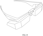
- FIGS 19 through 24 show yet another example embodiment of a virtual or augmented reality headset 310.
- the headset 310 includes a frame 312 and a pair of virtual or augmented reality eyepieces 330a, 330b supported by the frame 312.
- the frame 312 has opposing arm members 314a, 314b, a bridge 316 positioned intermediate the opposing arm members 314a, 314b, and a plurality of linear rails 318a, 318b. More particularly, a single linear rail 318a, 318b is provided at each of opposing sides 322, 324 of the frame 312 defined by a central reference plane 326.
- the linear rails 318a, 318b may be concealed or substantially concealed within the eyepieces 330a, 330b.
- the pair of virtual or augmented reality eyepieces 330a, 330b each have an optical center 332a, 332b, a distance between which defines an interpupillary distance IPD.
- the eyepieces 330a, 330b are movably coupled to the plurality of linear rails 318a, 318b to enable adjustment of the interpupillary distance IPD as desired to correspond to or more closely correspond to an actual interpupillary distance between the pupils of a wearer.
- the headset 310 further includes an adjustment mechanism 334 coupled to both of the pair of virtual or augmented reality eyepieces 330a, 330b.
- the adjustment mechanism 334 is operable to simultaneously move the eyepieces 330a, 330b in adjustment directions 342, 344 aligned with the linear rails 318a, 318b to adjust the interpupillary distance IPD.
- the virtual or augmented reality eyepieces 330a, 330b are movable between a fully collapsed or narrowest configuration ( Figures 19 , 20 and 22-24 ) and a fully expanded or widest configuration ( Figure 21 ).
- each individual eyepiece 330a, 330b may be adjusted a distance between about 10 mm and 12 mm. It is appreciated, however, that is some embodiments, more or less adjustment may be provided.
- a nosepiece 336 may be provided at the bridge 316 of the frame 312 to engage a nose of the user and support the virtual or augmented reality eyepieces 330a, 330b in front of the user's eyes during use.
- the nosepiece 336 may be integrally formed as a portion of the bridge 316, fixedly secured to the bridge 316 or removably coupled to the bridge 316.
- the nosepiece 336 may be removably coupleable to a base portion of the bridge 316 and impede the travel of the adjustment mechanism 334 to lock the virtual or augmented reality eyepieces 330a, 330b in a selected position.
- a lock may be provided on each eyepiece 330a, 330b, to clamp to a respective one of the linear rails 318a, 318b, or vice versa.
- a user may selectively unlock the eyepieces 330a, 330b for adjustment, adjust the eyepieces 330a, 330b transversely to a new interpupillary distance IPD, and lock the eyepieces 330a, 330b in place at the new interpupillary distance IPD.
- the lock may include, for example, one or more clamps, set screws, clips or other fasteners to impede movement of the adjustment mechanism 334 and/or eyepieces 330a, 330b, or otherwise fix the same in place.
- the lock may be spring-biased toward a locked position.
- each virtual or augmented reality eyepiece 330a, 330b may include a straight-line construction with flared lateral ends.
- a medial end of each eyepiece 330a, 330b may be positioned proximate the bridge 316 of the frame 312 and the lateral end may be positioned proximate a temple region of a respective one of the opposing arm members 314a, 314b.
- the frame 312 may include a respective straight-line construction on each of opposing sides 322, 324 of the central reference plane 326 that generally mimics that of the respective eyepieces 330a, 330b.
- the headset 310 includes a single linear rail 318a, 318b on each of opposing sides 322, 324 of the frame 312 to guide a respective one of the virtual or augmented reality eyepieces 330a, 330b.
- the linear rail 318a, 318b of each side 322, 324 may be located above a horizontal plane defined by the optical centers of the eyepiece 330a, 330b to guide an upper portion of the eyepiece 330a, 330b only.
- the eyepiece 330a, 330b may hang from the rails 318a, 318b.
- the eyepieces 330a, 330b may have a generally straight-lined construction and may move transversely along the linear rails 318a, 318b between an extreme medial position nearer the central plane 326 and an extreme lateral position farther from the central plane 326.
- the eyepieces 330a, 330b may be located at any position between the extreme end positions and secured in place with a lock or other fastening mechanism or fixation method.
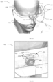
- FIGS 25 through 27 show another example embodiment of a virtual or augmented headset 410.
- the headset 410 includes a frame 412 and a pair of virtual or augmented reality eyepieces 430a, 430b supported by the frame 412.
- the frame has opposing arm members 414a, 414b, a bridge 416 positioned intermediate the opposing arm members 414a, 414b, and an adjustment mechanism 434.
- the adjustment mechanism 434 includes a rotary dial 436 with a coaxial output shaft or pin 438 that extends axially and rotatably couples to the bridge 416.
- a pair of gear pinions 440a, 440b are mounted to the output pin 438 and are positioned at opposite sides of the rotary dial 436.
- Gear pinions 440b may be a mirror image of gear pinion 440a, simply reflected across a plane that bisects the rotary dial 436 and is perpendicular to a rotational axis thereof.
- Each of the gear pinions 440a, 440b are sized and shaped to releasably and simultaneously engage a respective gear rack 442a, 442b.
- Each of the gear racks 442a, 442b are coupleable to a respective virtual or augmented reality eyepiece 430a, 430b.
- each opposing arm members 414a, 414b includes a respective guide pin 444 coupled thereto.
- the guide pins 444 are positioned proximate the temple region and, more particularly, between the temple and ear regions of a wearer.
- Each of the guide pins 444 extends through respective arm member apertures 446 and is received by a respective eyepiece aperture 448.
- a cylindrical projection 450 extends inwardly from each eyepiece aperture 448.
- the cylindrical projection 450 is sized and shaped to be slideably received by the respective arm member apertures 446 when the headset 410 is in a collapsed or narrowest configuration.
- the arm member apertures 446 may include a counterbore or a countersink to allow the guide pin 444 head to sit at least flush with an interior surface of the opposing arm members 414a, 414b to substantially or completely conceal the guide pin 444 from view when in the fully collapsed or narrowest configuration and/or when in the fully expanded or widest configuration.
- the opposing arm member apertures 446 may include bushings coupled thereto in order to reduce wear and friction, guide, or constrain the motion of the headset 410. The bushings may be lubricated or unlubricated.
- the interpupillary distance IPD can be conveniently controlled by a user.
- the gear racks 442a, 442b are sized and shaped to allow movement of the virtual or augmented reality eyepieces 430a, 430b relative to the rotary dial 436 such that a difference between the interpupillary distance IPD in the fully expanded or widest configuration ( Figures 25-27 ) and the interpupillary distance IPD in the fully collapsed or narrowest configuration is between 10 mm and about 12 mm. It is appreciated, however, that in some embodiments, more or less adjustment may be provided.
- the bridge 416 includes a recess 452 through which a portion of the rotary dial 436 protrudes outwardly.
- the user may rotate the rotary dial 436 to adjust the interpuppilary distance IPD until the optimal interpuppilary distance IPD for the user is determined.
- each of the virtual or augmented reality eyepieces 430a, 430b can be locked in place through a lock.
- the lock may include, for example, one or more clamps, set screws, clips or other fasteners to impede movement of the adjustment mechanism 34 and/or eyepieces 430a, 430b, or otherwise lock the same.
- the lock may be spring-biased toward a locked position.
- the adjustable mechanism 434 may further include a cover 453 to releasably attach to the recess 452 in the bridge 416.
- the cover 453 may substantially seal the adjustable mechanism 434 from the environment, such as water or moisture ingress, and may also selectively control access to the rotary dial 436 during use.
- the cover 453 may include male connectors that can snap into place when matingly received by a female connector located in the recess 452 of the bridge 416.
- the cover 453 may include any number of posts or pegs that may extend outwardly. The posts or pegs may be received by holes or dents in the recess 452 of the bridge 416 to releasably secure the cover 453 to the bridge 416.
- other mechanisms may be used to releasably attach the cover 453 to the headset 410.
- Figure 28 shows another example embodiment of a virtual or augmented headset 510 in an expanded or widest configuration.
- the headset includes a frame 512 and a pair of virtual or augmented reality eyepieces 530a, 530b supported by the frame 512.
- the frame has opposing arm members 514a, 514b, a bridge 516 positioned intermediate the opposing arm members 514a, 514b, and a plurality of linear rails 518a, 518b. More particularly, a single linear rail 518a, 518b is provided at each of opposing sides 522, 524 of the frame 512 defined by a central reference plane 526.
- the pair of virtual or augmented reality eyepieces 530a, 530b each has an optical center 532a, 532b, a distance between which defines an interpupillary distance IPD.
- the eyepieces 530a, 530b are movably coupled to the plurality of linear rails 518a, 518b to enable adjustment of the interpupillary distance IPD as desired to correspond to or more closely correspond to an actual interpupillary distance IPD between the pupils of a wearer.
- the headset 510 further includes an adjustment mechanism 534 coupled to both of the pair of virtual or augmented reality eyepieces 530a, 530b.
- the adjustment mechanism illustrated in Figure 28 includes a linear actuator device 560 to convert rotary motion into linear motion, such as a lead screw, jackscrew, ball screw, roller screw, or other types of devices that may mechanically convert rotary motion into linear motion.
- Figure 28 illustrates a lead screw with some of the hardware, such as a control knob, nuts, etc., removed for clarity.
- the linear actuator device 560 is coupled to a pair of links 562a, 562b.
- the links 562a, 562b are angularly spaced apart relative to each other and about the central reference plane 526. At a lower end, the links 562a, 562b are coupled to the respective linear rails 518a, 518b.
- the adjustment mechanism 534 allows the user to manipulate the interpupillary distance IPD by moving the virtual or augmented reality eyepieces 530a, 530b inwardly or outwardly relative to the adjustment mechanism 534.
- the user can rotate the control knob of the linear actuator device 560 in a clockwise direction, which causes a linear extension of the linear actuator device 560 shaft.
- This linear extension causes an increase in the angular displacement of the links 562a, 562b relative to one another, resulting in an outward linear translation of the respective rails 518a, 518b and the virtual or augmented reality eyepieces 530a, 530b.
- the user can rotate the control knob of the linear actuator device 560 in a counterclockwise direction to cause an inward movement of the virtual or augmented reality eyepieces 530a, 530b in a similar manner.
- the adjustment mechanism 534 can be substantially or completely concealed from view by housing the adjustment mechanism 534 within the bridge 516.
- the bridge 516 may further include a recess to allow a portion of the control knob to protrude outwardly.
- a cover may releasably attach to the recess in the bridge 516.
- the cover may substantially seal the adjustable mechanism 534 from the environment, such as water or moisture ingress, and may also selectively control access to the control knob during use.
- the cover may include male connectors that can snap into place when matingly received by a female connector located in the recess of the bridge 516.
- the cover may include any number of posts or pegs that may extend outwardly.
- the posts or pegs may be received by holes or dents in the recess of the bridge 516 to releasably secure the cover to the bridge 516.
- other mechanisms may be used to releasably attach the cover to the headset 510.
- the adjustment mechanisms described herein may be controlled electro-mechanically.
- One or more motors may be electro-mechanically coupled to the linear actuator device, such as a lead screw, jack screw, ball screw, roller screw, etc.
- the rotatory motion of the motors may be converted into linear motion through the linear actuator device to cause inward or outward movement of the virtual or augmented eyepieces.
- the motors may be a servo motor, stepper motor, or other types of electric motors.
- the motors may be electrically coupled to an electronic controller.
- the electronic controller may include a microcontroller and a motor driver to control and drive the motors.
- the microcontroller may comprise a microprocessor, memory, and a plurality of peripheral devices to form a system on a chip that may be applicable for a wide variety of applications.
- the adjustment mechanism may include one or more piezoelectric motors.
- the one or more piezoelectric motors may include piezoelectric linear actuators, which may be coupled to the virtual or augmented reality eyepieces to cause inward or outward movement of the virtual or augmented reality eyepieces.
- the piezoelectric motors may be electrically coupled to an electronic controller.
- the electronic controller may include a microcontroller and a piezoelectric motor driver to control and drive the piezoelectric motor.
- the microcontroller may comprise a microprocessor, memory, and a plurality of peripheral devices to form a system on a chip that may be applicable for a wide variety of applications.
Landscapes
- Physics & Mathematics (AREA)
- General Physics & Mathematics (AREA)
- Optics & Photonics (AREA)
- Health & Medical Sciences (AREA)
- Ophthalmology & Optometry (AREA)
- Engineering & Computer Science (AREA)
- Computer Graphics (AREA)
- Computer Hardware Design (AREA)
- General Engineering & Computer Science (AREA)
- Software Systems (AREA)
- Theoretical Computer Science (AREA)
- Eye Examination Apparatus (AREA)
- Pens And Brushes (AREA)
- Purses, Travelling Bags, Baskets, Or Suitcases (AREA)
- Inks, Pencil-Leads, Or Crayons (AREA)
- Eyeglasses (AREA)
- Microscoopes, Condenser (AREA)
Abstract
Description
- This disclosure generally relates to virtual or augmented reality headsets, and more particularly to virtual or augmented reality headsets wherein the interpupillary distance of the eyepieces is adjustable.
- Virtual or augmented reality headsets have long been proven invaluable for many applications, spanning the fields of scientific visualization, medicine and military training, engineering design and prototyping, tele-manipulation and tele-presence, and personal entertainment systems. In virtual reality systems, computer-generated virtual scenes are generally provided on an opaque display. In mixed and augmented reality systems, computer-generated virtual scenes or objects are combined with the views of a real-world scene on a see-through display. In many virtual or augmented reality headsets, virtual or augmented scenes are displayed on separate eyepieces. The interpupillary distance between the optical centers of such eyepieces are often fixed, and corrections that may be needed to adjust for variations in users having different interpupillary distances is made via software to provide corrective display adjustments. In some instances, the interpupillary distance between the optical centers of eyepieces may be mechanically adjustable; however, in such instances, adjustment devices can suffer from various drawbacks. For example, the adjustment mechanisms may be overly complex, bulky, lack precision and/or include a limited range of motion.
- Embodiments described herein provide virtual or augmented reality headsets with robust and efficient form factors that enable simultaneous movement of viewer eyepieces along one or more linear rails to provide interpupillary distance adjustment.
- A virtual or augmented reality headset may be summarized as including a frame, a pair of virtual or augmented reality eyepieces, and an adjustment mechanism coupled to both of the pair of virtual or augmented reality eyepieces. The frame may include opposing arm members, a bridge positioned intermediate the opposing arm members, and a plurality of linear rails. At least one linear rail may be provided at each of opposing sides of the frame defined by a central reference plane. The pair of virtual or augmented reality eyepieces each have an optical center and may be movably coupled to the plurality of linear rails of the frame to enable adjustment of an interpupillary distance between the optical centers. The adjustment mechanism may be operable to simultaneously move the pair of virtual or augmented reality eyepieces in adjustment directions aligned with the plurality of linear rails to adjust the interpupillary distance.
- The virtual or augmented reality eyepieces may be movable between a narrowest configuration and a widest configuration, and a difference between the interpupillary distance in the widest configuration and the interpupillary distance in the narrowest configuration may be between about 20 mm and about 24 mm.
- The adjustment mechanism may be coupled to the bridge of the frame and may include a manipulable actuator coupled to the virtual or augmented reality eyepieces for selectively adjusting a linear position of each of the virtual or augmented reality eyepieces simultaneously. The frame may further include a lock to selectively fix the virtual or augmented reality eyepieces in a selected linear position along the plurality of linear rails.
- The adjustment mechanism may include a manipulable actuator manually operable by a user and one or more links physically may couple the manipulable actuator to the virtual or augmented reality eyepieces. The headset may further include a selectively removable cover that is selectively positionable to alternatively prevent access to the manipulable actuator and to provide access to the manipulable actuator by the user. The manipulable actuator may be constrained to translate back and forth in directions perpendicular to the adjustment directions aligned with the plurality of linear rails, and movement of the manipulable actuator in one direction may move the virtual or augmented reality eyepieces toward an expanded configuration while movement of the manipulable actuator in the opposite direction may move the virtual or augmented reality eyepieces toward a collapsed configuration. The manipulable actuator may be accessible to the user while the headset is worn.
- The adjustment mechanism may include one or more linear actuators, such as, for example, a piezoelectric linear actuator or a motor-driven lead screw.
- The bridge of the frame may include a nosepiece to engage a nose of the user and support the virtual or augmented reality eyepieces in front of the user's eyes. The nosepiece may be removably coupleable to a base portion of the bridge to selectively lock the virtual or augmented reality eyepieces in a selected position.
- Each virtual or augmented reality eyepiece may be arcuate and may include a medial end and a lateral end. The medial end may be positioned proximate the bridge of the frame and the lateral end may be positioned proximate a temple region of a respective one of the opposing arm members. The frame may include a respective arcuate profile on each of opposing sides of the central reference plane to at least partially nest with a respective one of the virtual or augmented reality eyepieces when the virtual or augmented reality eyepieces are in a narrowest configuration in which the interpupillary distance is at a minimum. The plurality of linear rails may include at least two linear rails on each of opposing sides of the frame to guide a respective one of the virtual or augmented reality eyepieces, and wherein, for each of the opposing sides of the frame, a first one of the linear rails may be located proximate the bridge to guide the medial end of the respective virtual or augmented reality eyepiece and a second one of the linear rails may be located proximate the temple region to guide the lateral end of the respective virtual or augmented reality eyepiece. Each of the virtual or augmented reality eyepieces may be coupled to at least two linear rails that are offset fore and aft from each other.
- The plurality of linear rails of the frame may include at least two linear rails on each of opposing sides of the frame to guide a respective one of the virtual or augmented reality eyepieces, and wherein, for each of the opposing sides of the frame, the two linear rails may be located proximate the bridge to guide a medial end of the respective virtual or augmented reality eyepiece and support the respective virtual or augmented reality eyepiece in a cantilevered manner.
- The plurality of linear rails of the frame may include at least two linear rails on each of opposing sides of the frame vertically offset from each other to guide a respective one of the virtual or augmented reality eyepieces. For each of the opposing sides of the frame, the at least two linear rails and the arm member may form a fork structure. For each of the opposing sides of the frame, the two linear rails and a portion of the bridge may form a fork structure that supports the respective one of the virtual or augmented reality eyepieces.
- Each of the virtual or augmented reality eyepieces may be supported by a single respective linear rail underlying the eyepiece and supported in space only by a connection to the single respective linear rail. In other instances, each of the virtual or augmented reality eyepieces may be supported by a single respective linear rail positioned above a horizontal plane defined by the optical centers of the pair of virtual or augmented reality eyepieces and supported in space only by a connection to the single respective linear rail.
- The bridge and the plurality of rails of the frame may be integrally formed as a single-piece. The bridge, the opposing arm members and the plurality of rails of the frame may be integrally formed as a single-piece.
- The frame may further include a central frame portion comprising the bridge, and the opposing arm members may be hingedly connected to the central frame portion.
- The invention can also be directed to the following items:
- 1. A virtual or augmented reality headset, comprising:
- a frame including opposing arm members, a bridge positioned intermediate the opposing arm members, and a linear rail that extends across the bridge from one side of the frame to an opposing side of the frame;
- a pair of virtual or augmented reality eyepieces each having an optical center, the pair of virtual or augmented reality eyepieces movably coupled to the linear rail to enable adjustment of an interpupillary distance between the optical centers; and
- an adjustment mechanism coupled to both of the pair of virtual or augmented reality eyepieces and operable to simultaneously move the pair of virtual or augmented reality eyepieces in adjustment directions aligned with the linear rail to adjust the interpupillary distance.
- 2. The headset of
item 1 wherein the at least one linear rail provided at each of the opposing sides of the frame each form a portion of a composite linear rail that extends from one of the opposing sides to the other. - 3. The head set of
item 1, further comprising:
a pair of pins which slideably couple respective ones of the virtual or augmented reality eyepieces to respective ones of the opposing arm members. - 4. The head set of
item 1, further comprising:
a pair of pins which slideably couple respective ones of the virtual or augmented reality eyepieces to respective ones of the opposing arm members between a temple region and an ear region of the respective one of the opposing arm members. - 5. The head set of
item 4 wherein each of the pins is attached to the respective one of the opposing arm members and the virtual or augmented reality eyepieces each slideably receive the respective one of the pins via at least one aperture. - 6. The head set of item 5 wherein each of the pins is attached to the respective one of the opposing arm members and the virtual or augmented reality eyepieces each slideably receive respective ones of the pins via at least one aperture in the opposing arm members.
- 7. The head set of item 6 wherein each of the pins is attached to the respective one of the opposing arm members and the virtual or augmented reality eyepieces each slideably receive respective ones of the pins via a respective bushing located in a respective aperture in the opposing arm members.
- 8. The head set of
item 1 wherein the adjustment mechanism includes a recessed dial pivotally mounted to rotate about a rotation axis that extends outward from a front of the head set parallel each of a respective principal optical axis of the virtual or augmented reality eyepieces. - 9. The head set of
item 1 wherein the adjustment mechanism includes a cover releasably attachable to selectively prevent and allow access to the recessed dial. -
-
Figure 1 is a perspective view of a headset according to one embodiment. -
Figure 2 is a top plan view of a portion of the headset ofFigure 1 shown in a collapsed configuration. -
Figure 3 is a top plan view of a portion of the headset ofFigure 1 shown in an expanded configuration. -
Figure 4 is a top plan view of the headset ofFigure 1 shown in the collapsed configuration. -
Figure 5 is a front elevational view of the headset ofFigure 1 shown in the collapsed configuration. -
Figure 6 is a side elevational view of the headset ofFigure 1 shown in the collapsed configuration. -
Figure 7 is a perspective view of a headset according to another embodiment. -
Figure 8 is a front elevational view of the headset ofFigure 7 shown in a collapsed configuration. -
Figure 9 is a front elevational view of the headset ofFigure 7 shown in an expanded configuration. -
Figure 10 is a top plan view of the headset ofFigure 7 shown in the collapsed configuration. -
Figure 11 is a front elevational view of the headset ofFigure 7 shown in the collapsed configuration. -
Figure 12 is a side elevational view of the headset ofFigure 7 shown in the collapsed configuration. -
Figure 13 is a perspective view of a headset according to another embodiment. -
Figure 14 is a front elevational view of the headset ofFigure 13 shown in a collapsed configuration. -
Figure 15 is a front elevational view of the headset ofFigure 13 shown in an expanded configuration. -
Figure 16 is a top plan view of the headset ofFigure 13 shown in the collapsed configuration. -
Figure 17 is a front elevational view of the headset ofFigure 13 shown in the collapsed configuration. -
Figure 18 is a side elevational view of the headset ofFigure 13 shown in the collapsed configuration. -
Figure 19 is a perspective view of a headset according to another embodiment. -
Figure 20 is a front perspective view of a portion of the headset ofFigure 19 shown in a collapsed configuration. -
Figure 21 is a front perspective view of a portion of the headset ofFigure 19 shown in an expanded configuration. -
Figure 22 is a top plan view of the headset ofFigure 19 shown in the collapsed configuration. -
Figure 23 is a front elevational view of the headset ofFigure 19 shown in the collapsed configuration. -
Figure 24 is a side elevational view of the headset ofFigure 19 shown in the collapsed configuration. -
Figure 25 is a perspective view of a portion of a headset shown in an expanded configuration according to another embodiment. -
Figure 26 is an enlarged perspective view of a portion of the headset ofFigure 25 showing an adjustable mechanism. -
Figure 27 is a partial cutaway perspective view of the headset ofFigure 25 . -
Figure 28 is a front elevational view of a headset shown in an expanded configuration according to yet another embodiment. - In the following description, certain specific details are set forth in order to provide a thorough understanding of various disclosed embodiments. However, one skilled in the relevant art will recognize that embodiments may be practiced without one or more of these specific details, or with other methods, components, materials, etc. In other instances, well-known structures associated with virtual and augmented reality systems have not been shown or described in detail to avoid unnecessarily obscuring descriptions of the embodiments.
- Unless the context requires otherwise, throughout the specification and claims which follow, the word "comprise" and variations thereof, such as, "comprises" and "comprising" are to be construed in an open, inclusive sense that is as "including, but not limited to."
- Reference throughout this specification to "one embodiment" or "an embodiment" means that a particular feature, structure or characteristic described in connection with the embodiment is included in at least one embodiment. Thus, the appearances of the phrases "in one embodiment" or "in an embodiment" in various places throughout this specification are not necessarily all referring to the same embodiment. Furthermore, the particular features, structures, or characteristics may be combined in any suitable manner in one or more embodiments.
-
Figures 1 through 6 show one example embodiment of a virtual oraugmented reality headset 10. Theheadset 10 includes aframe 12 and a pair of virtual oraugmented reality eyepieces frame 12. Theframe 12 has opposingarm members bridge 16 positioned intermediate theopposing arm members linear rails linear rails sides frame 12 defined by acentral reference plane 26. - The pair of virtual or
augmented reality eyepieces optical center eyepieces linear rails - The
headset 10 further includes anadjustment mechanism 34 coupled to both of the pair of virtual oraugmented reality eyepieces adjustment mechanism 34 is operable to simultaneously move theeyepieces adjustment directions linear rails augmented reality eyepieces Figures 1 ,2 and4-6 ) and a fully expanded or widest configuration (Figure 3 ). Theframe 12,eyepieces rails individual eyepiece - A
nosepiece 36 may be provided at thebridge 16 of theframe 12 to engage a nose of the user and support the virtual oraugmented reality eyepieces nosepiece 36 may be integrally formed as a portion of thebridge 16, fixedly secured to thebridge 16, or removably coupled to thebridge 16. In some embodiments, thenosepiece 36 may be removably coupleable to a base portion of thebridge 16 and impede the travel of theadjustment mechanism 34 to lock the virtual oraugmented reality eyepieces eyepiece linear rails eyepieces eyepieces eyepieces adjustment mechanism 34 and/oreyepieces - With continued reference to
Figures 1 through 6 , each virtual or augmentedreality eyepiece bridge 16 of theframe 12 and the lateral end may be positioned proximate a temple region of a respective one of theopposing arm members frame 12 may include a respective arcuate profile on each of opposingsides central reference plane 26 to at least partially nest with a respective one of the virtual oraugmented reality eyepieces augmented reality eyepieces Figures 1 ,2 and5-6 ) in which the interpupillary distance IPD is at a minimum. - The
headset 10 may include a pair oflinear rails sides frame 12 to guide a respective one of the virtual oraugmented reality eyepieces sides frame 12, a first one of thelinear rails bridge 16 to guide the medial end of the respective virtual or augmentedreality eyepiece linear rails reality eyepiece augmented reality eyepieces linear rails frame 12. In some instances, therails - As can be appreciated from the embodiment shown in
Figures 1 through 6 , theeyepieces linear rails central plane 26 and an extreme lateral position farther from thecentral plane 26. Theeyepieces -
Figures 7 through 12 show another example embodiment of a virtual oraugmented reality headset 110. Theheadset 110 includes aframe 112 and a pair of virtual oraugmented reality eyepieces frame 112. Theframe 112 has opposingarm members bridge 116 positioned intermediate theopposing arm members linear rails linear rails sides frame 112 defined by acentral reference plane 126. As shown inFigures 7 through 12 , thelinear rails eyepieces - Again, the pair of virtual or
augmented reality eyepieces optical center eyepieces linear rails - The
headset 110 further includes anadjustment mechanism 134 coupled to both of the pair of virtual oraugmented reality eyepieces adjustment mechanism 134 is operable to simultaneously move theeyepieces adjustment directions linear rails augmented reality eyepieces Figures 7 ,8 and10-12 ) and a fully expanded or widest configuration (Figure 9 ). Theframe 112,eyepieces rails individual eyepiece - Again, a
nosepiece 136 may be provided at thebridge 116 of theframe 112 to engage a nose of the user and support the virtual oraugmented reality eyepieces nosepiece 136 may be integrally formed as a portion of thebridge 116, fixedly secured to thebridge 116, or removably coupled to thebridge 116. In some embodiments, thenosepiece 136 may be removably coupleable to a base portion of thebridge 116 and impede the travel of theadjustment mechanism 134 to lock the virtual oraugmented reality eyepieces eyepiece linear rails eyepieces eyepieces eyepieces adjustment mechanism 134 and/oreyepieces - With continued reference to
Figures 7 through 12 , each virtual or augmentedreality eyepiece bridge 116 of theframe 112 and the lateral end may be positioned proximate a temple region of a respective one of theopposing arm members frame 112 may include a respective arcuate profile on each of opposingsides central reference plane 126 that generally reflects that of the respective virtual oraugmented reality eyepieces - The
headset 110 may include a pair oflinear rails sides frame 112 to guide a respective one of the virtual oraugmented reality eyepieces sides frame 112, a first one of thelinear rails bridge 116 at an upper region of theheadset 110 to guide an upper portion of the medial end of the respective virtual or augmentedreality eyepiece linear rails bridge 116 at a lower region of theheadset 110 to guide a lower portion of the medial end of the respective virtual or augmentedreality eyepiece linear rails sides frame 112 to guide a respective one of the virtual oraugmented reality eyepieces linear rails side bridge 16 to guide the medial end of the respective virtual or augmentedreality eyepiece linear rails sides frame 112 may be vertically offset from each other and may form a fork structure with arespective arm member frame 112. Theeyepieces linear rails sides frame 112 and a portion of thebridge 116 may form a fork structure oriented away from thecentral plane 126 to support theeyepieces - As can be appreciated from the embodiment shown in
Figures 7 through 12 , theeyepieces linear rails central plane 126 and an extreme lateral position farther from thecentral plane 126. Theeyepieces -
Figures 13 through 18 show another example embodiment of a virtual oraugmented reality headset 210. Theheadset 210 includes aframe 212 and a pair of virtual oraugmented reality eyepieces frame 212. Theframe 212 has opposingarm members bridge 216 positioned intermediate theopposing arm members linear rails linear rail sides frame 212 defined by acentral reference plane 226. As shown inFigures 13 through 18 , thelinear rails eyepieces - Again, the pair of virtual or
augmented reality eyepieces optical center eyepieces linear rails - The
headset 210 further includes anadjustment mechanism 234 coupled to both of the pair of virtual oraugmented reality eyepieces adjustment mechanism 234 is operable to simultaneously move theeyepieces adjustment directions linear rails augmented reality eyepieces Figures 13 ,14 and16-18 ) and a fully expanded or widest configuration (Figure 15 ). Theframe 212,eyepieces rails individual eyepiece - Again, a
nosepiece 236 may be provided at thebridge 216 of theframe 212 to engage a nose of the user and support the virtual oraugmented reality eyepieces nosepiece 236 may be integrally formed as a portion of thebridge 216, fixedly secured to thebridge 216 or removably coupled to thebridge 216. In some embodiments, thenosepiece 236 may be removably coupleable to a base portion of thebridge 216 and impede the travel of theadjustment mechanism 234 to lock the virtual oraugmented reality eyepieces eyepiece linear rails eyepieces eyepieces eyepieces adjustment mechanism 234 and/oreyepieces - With continued reference to
Figures 13 through 18 , each virtual or augmentedreality eyepiece bridge 216 of theframe 212 and the lateral end may be positioned proximate a temple region of a respective one of theopposing arm members frame 212 may include a respective arcuate profile on each of opposingsides central reference plane 226 that generally transitions with that of therespective eyepieces - The
headset 210 includes a singlelinear rail sides frame 212 to guide a respective one of the virtual oraugmented reality eyepieces linear rail side bridge 216 and may underlay therespective eyepiece eyepiece - As can be appreciated from the embodiment shown in
Figures 13 through 18 , theeyepieces linear rails central plane 226 and an extreme lateral position farther from thecentral plane 226. Theeyepieces -
Figures 19 through 24 show yet another example embodiment of a virtual oraugmented reality headset 310. Theheadset 310 includes aframe 312 and a pair of virtual oraugmented reality eyepieces frame 312. Theframe 312 has opposingarm members bridge 316 positioned intermediate theopposing arm members linear rails linear rail sides frame 312 defined by acentral reference plane 326. As shown inFigures 19 through 24 , thelinear rails eyepieces - Again, the pair of virtual or
augmented reality eyepieces optical center eyepieces linear rails - The
headset 310 further includes anadjustment mechanism 334 coupled to both of the pair of virtual oraugmented reality eyepieces adjustment mechanism 334 is operable to simultaneously move theeyepieces adjustment directions linear rails augmented reality eyepieces Figures 19 ,20 and22-24 ) and a fully expanded or widest configuration (Figure 21 ). Theframe 312,eyepieces rails individual eyepiece - Again, a
nosepiece 336 may be provided at thebridge 316 of theframe 312 to engage a nose of the user and support the virtual oraugmented reality eyepieces nosepiece 336 may be integrally formed as a portion of thebridge 316, fixedly secured to thebridge 316 or removably coupled to thebridge 316. In some embodiments, thenosepiece 336 may be removably coupleable to a base portion of thebridge 316 and impede the travel of theadjustment mechanism 334 to lock the virtual oraugmented reality eyepieces eyepiece linear rails eyepieces eyepieces eyepieces adjustment mechanism 334 and/oreyepieces - With continued reference to
Figures 19 through 24 , each virtual or augmentedreality eyepiece eyepiece bridge 316 of theframe 312 and the lateral end may be positioned proximate a temple region of a respective one of theopposing arm members frame 312 may include a respective straight-line construction on each of opposingsides central reference plane 326 that generally mimics that of therespective eyepieces - The
headset 310 includes a singlelinear rail sides frame 312 to guide a respective one of the virtual oraugmented reality eyepieces linear rail side eyepiece eyepiece eyepiece rails - As can be appreciated from the embodiment shown in
Figures 19 through 24 , theeyepieces linear rails central plane 326 and an extreme lateral position farther from thecentral plane 326. Theeyepieces -
Figures 25 through 27 show another example embodiment of a virtual oraugmented headset 410. Theheadset 410 includes aframe 412 and a pair of virtual oraugmented reality eyepieces frame 412. The frame has opposingarm members bridge 416 positioned intermediate theopposing arm members adjustment mechanism 434. Theadjustment mechanism 434 includes arotary dial 436 with a coaxial output shaft or pin 438 that extends axially and rotatably couples to thebridge 416. A pair ofgear pinions output pin 438 and are positioned at opposite sides of therotary dial 436. Gear pinions 440b may be a mirror image ofgear pinion 440a, simply reflected across a plane that bisects therotary dial 436 and is perpendicular to a rotational axis thereof. Each of thegear pinions respective gear rack gear racks reality eyepiece - With continued reference to
Figures 25 through 27 , each opposingarm members headset 410 is in a collapsed or narrowest configuration. In some embodiments, the arm member apertures 446 may include a counterbore or a countersink to allow the guide pin 444 head to sit at least flush with an interior surface of theopposing arm members headset 410. The bushings may be lubricated or unlubricated. - With continued reference to
Figures 25-27 , rotation of thegear pinions rotary dial 436 in a clockwise direction causes thegear pinions respective gear racks augmented reality eyepieces rotary dial 436. At the temporal or lateral end, moreover, the guide pins 444 assist in guiding the virtual oraugmented reality eyepieces opposing arm members rotary dial 436 causes thegear racks rotary dial 436. Similarly, the guide pins 444 assist in guiding the virtual oraugmented reality eyepieces opposing arm members - By manipulating the
adjustment mechanism 434 to move the virtual oraugmented reality eyepieces headset 410, thegear racks augmented reality eyepieces rotary dial 436 such that a difference between the interpupillary distance IPD in the fully expanded or widest configuration (Figures 25-27 ) and the interpupillary distance IPD in the fully collapsed or narrowest configuration is between 10 mm and about 12 mm. It is appreciated, however, that in some embodiments, more or less adjustment may be provided. - To allow the user access to the
rotary dial 436, thebridge 416 includes arecess 452 through which a portion of therotary dial 436 protrudes outwardly. The user may rotate therotary dial 436 to adjust the interpuppilary distance IPD until the optimal interpuppilary distance IPD for the user is determined. Once the optimal interpuppilary distance IPD is set, each of the virtual oraugmented reality eyepieces adjustment mechanism 34 and/oreyepieces - The
adjustable mechanism 434 may further include a cover 453 to releasably attach to therecess 452 in thebridge 416. The cover 453 may substantially seal theadjustable mechanism 434 from the environment, such as water or moisture ingress, and may also selectively control access to therotary dial 436 during use. In some embodiments, the cover 453 may include male connectors that can snap into place when matingly received by a female connector located in therecess 452 of thebridge 416. In other embodiments, the cover 453 may include any number of posts or pegs that may extend outwardly. The posts or pegs may be received by holes or dents in therecess 452 of thebridge 416 to releasably secure the cover 453 to thebridge 416. As can be appreciated from the foregoing, other mechanisms may be used to releasably attach the cover 453 to theheadset 410. -
Figure 28 shows another example embodiment of a virtual or augmented headset 510 in an expanded or widest configuration. The headset includes aframe 512 and a pair of virtual oraugmented reality eyepieces frame 512. The frame has opposingarm members opposing arm members linear rails linear rail sides frame 512 defined by acentral reference plane 526. - Again, the pair of virtual or
augmented reality eyepieces optical center eyepieces linear rails - The headset 510 further includes an
adjustment mechanism 534 coupled to both of the pair of virtual oraugmented reality eyepieces Figure 28 includes alinear actuator device 560 to convert rotary motion into linear motion, such as a lead screw, jackscrew, ball screw, roller screw, or other types of devices that may mechanically convert rotary motion into linear motion. By way of example,Figure 28 illustrates a lead screw with some of the hardware, such as a control knob, nuts, etc., removed for clarity. Thelinear actuator device 560 is coupled to a pair oflinks links central reference plane 526. At a lower end, thelinks linear rails - The
adjustment mechanism 534 allows the user to manipulate the interpupillary distance IPD by moving the virtual oraugmented reality eyepieces adjustment mechanism 534. The user can rotate the control knob of thelinear actuator device 560 in a clockwise direction, which causes a linear extension of thelinear actuator device 560 shaft. This linear extension causes an increase in the angular displacement of thelinks respective rails augmented reality eyepieces linear actuator device 560 in a counterclockwise direction to cause an inward movement of the virtual oraugmented reality eyepieces - The
adjustment mechanism 534 can be substantially or completely concealed from view by housing theadjustment mechanism 534 within the bridge 516. The bridge 516 may further include a recess to allow a portion of the control knob to protrude outwardly. A cover may releasably attach to the recess in the bridge 516. The cover may substantially seal theadjustable mechanism 534 from the environment, such as water or moisture ingress, and may also selectively control access to the control knob during use. In some embodiments, the cover may include male connectors that can snap into place when matingly received by a female connector located in the recess of the bridge 516. In other embodiments, the cover may include any number of posts or pegs that may extend outwardly. The posts or pegs may be received by holes or dents in the recess of the bridge 516 to releasably secure the cover to the bridge 516. As can be appreciated from the foregoing, other mechanisms may be used to releasably attach the cover to the headset 510. - In some embodiments, the adjustment mechanisms described herein may be controlled electro-mechanically. One or more motors may be electro-mechanically coupled to the linear actuator device, such as a lead screw, jack screw, ball screw, roller screw, etc. The rotatory motion of the motors may be converted into linear motion through the linear actuator device to cause inward or outward movement of the virtual or augmented eyepieces. The motors may be a servo motor, stepper motor, or other types of electric motors. To control movement of the virtual or augmented eyepieces, the motors may be electrically coupled to an electronic controller. The electronic controller may include a microcontroller and a motor driver to control and drive the motors. Moreover, the microcontroller may comprise a microprocessor, memory, and a plurality of peripheral devices to form a system on a chip that may be applicable for a wide variety of applications.
- In some embodiments, the adjustment mechanism may include one or more piezoelectric motors. The one or more piezoelectric motors may include piezoelectric linear actuators, which may be coupled to the virtual or augmented reality eyepieces to cause inward or outward movement of the virtual or augmented reality eyepieces. To control movement of the virtual or augmented eyepieces, the piezoelectric motors may be electrically coupled to an electronic controller. The electronic controller may include a microcontroller and a piezoelectric motor driver to control and drive the piezoelectric motor. Moreover, the microcontroller may comprise a microprocessor, memory, and a plurality of peripheral devices to form a system on a chip that may be applicable for a wide variety of applications.
- Moreover, the various embodiments described above can be combined to provide further embodiments.
U.S. patent application Serial No. 61/891,801, filed October 16, 2013 - These and other changes can be made to the embodiments in light of the above-detailed description. In general, in the following claims, the terms used should not be construed to limit the claims to the specific embodiments disclosed in the specification and the claims, but should be construed to include all possible embodiments along with the full scope of equivalents to which such claims are entitled. Accordingly, the claims are not limited by the disclosure.
Claims (15)
- A virtual or augmented reality headset (10), comprising:a frame (12) including opposing arm members (14a, 14b), a bridge (16) positioned intermediate the opposing arm members (14a, 14b), and a plurality of linear rails (18a, 18b, 20a, 20b), at least one linear rail provided at each of opposing sides of the frame (12) defined by a central reference plane (26);a pair of virtual or augmented reality eyepieces (30a, 30b) each having an optical center, the pair of virtual or augmented reality eyepieces (30a, 30b) movably coupled to the plurality of linear rails (18a, 18bm 20a, 20b) to enable adjustment of an interpupillary distance between the optical centers; andan adjustment mechanism (34) coupled to both of the pair of virtual or augmented reality eyepieces (30a, 30b) and operable to simultaneously move the pair of virtual or augmented reality eyepieces (30a, 30b) in adjustment directions aligned with the plurality of linear rails (18a, 18b, 20a, 20b) to adjust the interpupillary distance;characterized in thateach virtual or augmented reality eyepiece (30a, 30b) is arcuate and includes a medial end and a lateral end, the medial end positioned proximate the bridge (16) of the frame (12) and the lateral end positioned proximate a temple region of a respective one of the opposing arm members (14a, 14b); andthe plurality of linear rails (18a, 18b, 20a, 20b) include at least two linear rails on each of the opposing sides of the frame to guide a respective one of the virtual or augmented reality eyepieces (30a, 30b), and wherein, for each of the opposing sides of the frame (12), a first one (18a, 18b) of the linear rails is located proximate the bridge (16) to guide the medial end of the respective virtual or augmented reality eyepiece (30a, 30b) and a second one (20a, 20b) of the linear rails is located proximate the temple region to guide the lateral end of the respective virtual or augmented reality eyepiece (30a, 30b).
- The headset (10) of claim 1 wherein the virtual or augmented reality eyepieces (30a, 30b) are movable between a narrowest configuration and a widest configuration, and wherein a difference between the interpupillary distance in the widest configuration and the interpupillary distance in the narrowest configuration is between about 20 mm and about 24 mm.
- The headset (10) of claim 1 wherein the adjustment mechanism (34) is coupled to the bridge (16) and includes a manipulable actuator coupled to the virtual or augmented reality eyepieces (30a, 30b) for selectively adjusting a linear position of each of the virtual or augmented reality eyepieces simultaneously.
- The headset (10) of one of claims 1 and 2, wherein the frame (12) further includes a lock to selectively fix the virtual or augmented reality eyepieces (30a, 30b) in a selected linear position along the plurality of linear rails (18a, 18b, 20a, 20b).
- The headset (10) of any one of claims 1 to 4, wherein the adjustment mechanism (34) includes a manipulable actuator manually operable by a user and one or more links physically coupling the manipulable actuator to the virtual or augmented reality eyepieces (30a, 30b).
- The headset (10) of claim 5, further comprising:
a selectively removable cover that is selectively positionable to alternatively prevent access to the manipulable actuator and to provide access to the manipulable actuator by the user. - The headset (10) of claim 6 wherein the manipulable actuator is constrained to translate back and forth in directions perpendicular to the adjustment directions aligned with the plurality of linear rails (18a, 18b, 20a, 20b), and wherein movement of the manipulable actuator in one direction moves the virtual or augmented reality eyepieces (30a, 30b) toward an expanded configuration and movement of the manipulable actuator in the opposite direction moves the virtual or augmented reality eyepieces (30a, 30b) toward a collapsed configuration.
- The headset (10) of claim 5 wherein the manipulable actuator is accessible to the user while the headset is worn.
- The headset (10) of any one of claims 1 to 8, wherein the adjustment mechanism includes one or more linear actuators, preferably wherein the one or more linear actuators comprise at least one piezoelectric linear actuator.
- The headset (10) of any one of claims 1 to 9, wherein the bridge (16) includes a nosepiece (36) to engage a nose of a user and support the virtual or augmented reality eyepieces (30a, 30b) in front of the user's eyes, preferably wherein the bridge (16) further includes a base portion, and wherein the nosepiece is removably coupleable to the base portion to selectively lock the virtual or augmented reality eyepieces (30a, 30b) in a selected position.
- The headset (10) of any one of claims 1 to 10, wherein the frame (12) includes a respective arcuate profile on each of opposing sides of the central reference plane (26) to at least partially nest with a respective one of the virtual or augmented reality eyepieces (30a, 30b) when the virtual or augmented reality eyepieces (30a, 30b) are in a narrowest configuration in which the interpupillary distance is at a minimum.
- The headset (10) of any one of claims 1 to 11, wherein each of the virtual or augmented reality eyepieces (30a, 30b) are coupled to at least two linear rails that are offset fore and aft from each other.
- The headset (10) of any one of claims 1 to 112, wherein the plurality of linear rails (18a, 18b, 20a, 20b) include at least two linear rails on each of the opposing sides of the frame vertically offset from each other to guide a respective one of the virtual or augmented reality eyepieces (30a, 30b).
- The headset (10) of any one of claims 1 to 13, wherein the bridge (16) and the plurality of rails (18a, 18b, 20a, 20b) of the frame (12) are integrally formed as a single-piece, or the bridge (16), the opposing arm members (14a, 14b) and the plurality of rails (18a, 18b, 20a, 20b) of the frame (12) are integrally formed as a single-piece.
- The headset (10) of any one of claims 1 to 14, wherein the frame (12) further includes a central frame portion comprising the bridge (16), and wherein the opposing arm members (14a, 14b) are hingedly connected to the central frame portion.
Applications Claiming Priority (3)
| Application Number | Priority Date | Filing Date | Title |
|---|---|---|---|
| US201361891801P | 2013-10-16 | 2013-10-16 | |
| PCT/US2014/060955 WO2015057994A1 (en) | 2013-10-16 | 2014-10-16 | Virtual or augmented reality headsets having adjustable interpupillary distance |
| EP14853812.7A EP3058418B1 (en) | 2013-10-16 | 2014-10-16 | Virtual or augmented reality headsets having adjustable interpupillary distance |
Related Parent Applications (1)
| Application Number | Title | Priority Date | Filing Date |
|---|---|---|---|
| EP14853812.7A Division EP3058418B1 (en) | 2013-10-16 | 2014-10-16 | Virtual or augmented reality headsets having adjustable interpupillary distance |
Publications (2)
| Publication Number | Publication Date |
|---|---|
| EP4321915A2 true EP4321915A2 (en) | 2024-02-14 |
| EP4321915A3 EP4321915A3 (en) | 2024-05-01 |
Family
ID=52809388
Family Applications (2)
| Application Number | Title | Priority Date | Filing Date |
|---|---|---|---|
| EP14853812.7A Active EP3058418B1 (en) | 2013-10-16 | 2014-10-16 | Virtual or augmented reality headsets having adjustable interpupillary distance |
| EP23201335.9A Pending EP4321915A3 (en) | 2013-10-16 | 2014-10-16 | Virtual or augmented reality headsets having adjustable interpupillary distance |
Family Applications Before (1)
| Application Number | Title | Priority Date | Filing Date |
|---|---|---|---|
| EP14853812.7A Active EP3058418B1 (en) | 2013-10-16 | 2014-10-16 | Virtual or augmented reality headsets having adjustable interpupillary distance |
Country Status (9)
| Country | Link |
|---|---|
| US (5) | US9470906B2 (en) |
| EP (2) | EP3058418B1 (en) |
| JP (2) | JP6479785B2 (en) |
| KR (4) | KR102953540B1 (en) |
| CN (1) | CN105829953B (en) |
| AU (1) | AU2014337171B2 (en) |
| CA (2) | CA2927818C (en) |
| IL (4) | IL312213A (en) |
| WO (1) | WO2015057994A1 (en) |
Families Citing this family (327)
| Publication number | Priority date | Publication date | Assignee | Title |
|---|---|---|---|---|
| US10073264B2 (en) | 2007-08-03 | 2018-09-11 | Lumus Ltd. | Substrate-guide optical device |
| IL219907A (en) | 2012-05-21 | 2017-08-31 | Lumus Ltd | Head-mounted display eyeball tracker integrated system |
| EP3058418B1 (en) * | 2013-10-16 | 2023-10-04 | Magic Leap, Inc. | Virtual or augmented reality headsets having adjustable interpupillary distance |
| US10430985B2 (en) | 2014-03-14 | 2019-10-01 | Magic Leap, Inc. | Augmented reality systems and methods utilizing reflections |
| US11138793B2 (en) | 2014-03-14 | 2021-10-05 | Magic Leap, Inc. | Multi-depth plane display system with reduced switching between depth planes |
| RU2655613C1 (en) * | 2017-07-05 | 2018-05-29 | Алексей Леонидович УШАКОВ | Swivel glasses (options) |
| AU2015323940B2 (en) | 2014-09-29 | 2021-05-20 | Magic Leap, Inc. | Architectures and methods for outputting different wavelength light out of waveguides |
| KR102295452B1 (en) | 2014-10-24 | 2021-08-27 | 이매진 코퍼레이션 | Microdisplay based immersive headset |
| JP2016090689A (en) * | 2014-10-31 | 2016-05-23 | セイコーエプソン株式会社 | Image display apparatus and drawing method |
| US9472025B2 (en) * | 2015-01-21 | 2016-10-18 | Oculus Vr, Llc | Compressible eyecup assemblies in a virtual reality headset |
| NZ773822A (en) | 2015-03-16 | 2022-07-29 | Magic Leap Inc | Methods and systems for diagnosing and treating health ailments |
| US20160300391A1 (en) * | 2015-04-07 | 2016-10-13 | Purdue Research Foundation | System and method for reducing simulator sickness |
| WO2016191960A1 (en) * | 2015-05-29 | 2016-12-08 | 深圳市柔宇科技有限公司 | Display module and electronic device having display module |
| IL256276B (en) | 2015-06-15 | 2022-09-01 | Magic Leap Inc | Display system with optical elements for in-coupling multiplexed light streams |
| KR102689919B1 (en) | 2015-08-18 | 2024-07-30 | 매직 립, 인코포레이티드 | Virtual and augmented reality systems and methods |
| CN108135469B (en) | 2015-08-21 | 2021-03-09 | 奇跃公司 | Eyelid shape estimation using eye pose measurements |
| KR102726941B1 (en) | 2015-08-21 | 2024-11-05 | 매직 립, 인코포레이티드 | Eyelid shape estimation |
| KR102351060B1 (en) | 2015-09-16 | 2022-01-12 | 매직 립, 인코포레이티드 | Mixing Head Pose of Audio Files |
| CN108351527B (en) | 2015-09-23 | 2024-06-18 | 奇跃公司 | Eye imaging using off-axis imagers |
| US10630965B2 (en) | 2015-10-02 | 2020-04-21 | Microsoft Technology Licensing, Llc | Calibrating a near-eye display |
| EP3362946B1 (en) | 2015-10-16 | 2020-08-26 | Magic Leap, Inc. | Eye pose identification using eye features |
| CN113220116A (en) | 2015-10-20 | 2021-08-06 | 奇跃公司 | System and method for changing user input mode of wearable device and wearable system |
| WO2017079329A1 (en) | 2015-11-04 | 2017-05-11 | Magic Leap, Inc. | Dynamic display calibration based on eye-tracking |
| US11231544B2 (en) | 2015-11-06 | 2022-01-25 | Magic Leap, Inc. | Metasurfaces for redirecting light and methods for fabricating |
| JP6620553B2 (en) * | 2015-12-28 | 2019-12-18 | セイコーエプソン株式会社 | Virtual image display device |
| KR102439768B1 (en) | 2016-01-07 | 2022-09-01 | 매직 립, 인코포레이티드 | Virtual and augmented reality systems and methods with an unequal number of component color images distributed across depth planes |
| CN118605029A (en) | 2016-01-19 | 2024-09-06 | 奇跃公司 | Augmented reality system and method using images |
| US10831264B2 (en) | 2016-01-19 | 2020-11-10 | Magic Leap, Inc. | Eye image combination |
| CA3013025A1 (en) | 2016-01-29 | 2017-08-03 | Magic Leap, Inc. | Display for three-dimensional image |
| IL260939B2 (en) | 2016-02-11 | 2023-10-01 | Magic Leap Inc | Multi-depth plane display system with reduced switching between depth planes |
| US10302957B2 (en) | 2016-02-24 | 2019-05-28 | Magic Leap, Inc. | Polarizing beam splitter with low light leakage |
| IL303148A (en) | 2016-02-24 | 2023-07-01 | Magic Leap Inc | Low profile interconnect for light emitter |
| EP3420601B1 (en) | 2016-02-26 | 2023-08-02 | Magic Leap, Inc. | Optical system |
| CA3015210A1 (en) | 2016-02-26 | 2017-08-31 | Magic Leap, Inc. | Display system having a plurality of light pipes for a plurality of light emitters |
| US10422976B2 (en) | 2016-02-26 | 2019-09-24 | Samsung Electronics Co., Ltd. | Aberration corrected optical system for near-eye displays |
| EP3423887B1 (en) | 2016-03-01 | 2023-07-12 | Magic Leap, Inc. | Reflective switching device for inputting different wavelengths of light into waveguides |
| CN114690881A (en) | 2016-03-04 | 2022-07-01 | 奇跃公司 | Display system for reducing power consumption and method for reducing power consumption of display system |
| CA3016189A1 (en) | 2016-03-07 | 2017-09-14 | Magic Leap, Inc. | Blue light adjustment for biometric security |
| CA3017795A1 (en) | 2016-03-22 | 2017-09-28 | Magic Leap, Inc. | Head mounted display system configured to exchange biometric information |
| US10698215B2 (en) | 2016-03-25 | 2020-06-30 | Magic Leap, Inc. | Virtual and augmented reality systems and methods |
| US10359806B2 (en) * | 2016-03-28 | 2019-07-23 | Sony Interactive Entertainment Inc. | Pressure sensing to identify fitness and comfort of virtual reality headset |
| US10815145B2 (en) | 2016-03-31 | 2020-10-27 | Corning Incorporated | High index glass and devices incorporating such |
| KR102438052B1 (en) | 2016-03-31 | 2022-08-29 | 매직 립, 인코포레이티드 | 3D virtual objects and interactions using poses and multi-DOF controllers |
| EP3440497B1 (en) | 2016-04-08 | 2023-08-16 | Magic Leap, Inc. | Augmented reality systems and methods with variable focus lens elements |
| JP7118007B2 (en) | 2016-04-21 | 2022-08-15 | マジック リープ, インコーポレイテッド | Visual backlight around the field of view |
| NZ747815A (en) | 2016-04-26 | 2023-05-26 | Magic Leap Inc | Electromagnetic tracking with augmented reality systems |
| JP6961619B2 (en) | 2016-05-06 | 2021-11-05 | マジック リープ, インコーポレイテッドMagic Leap, Inc. | Meta-surface with asymmetric lattice for redirecting light and manufacturing method |
| AU2017264695B2 (en) | 2016-05-09 | 2022-03-31 | Magic Leap, Inc. | Augmented reality systems and methods for user health analysis |
| US9904058B2 (en) | 2016-05-12 | 2018-02-27 | Magic Leap, Inc. | Distributed light manipulation over imaging waveguide |
| WO2017201329A1 (en) | 2016-05-20 | 2017-11-23 | Magic Leap, Inc. | Contextual awareness of user interface menus |
| KR20240036149A (en) | 2016-06-03 | 2024-03-19 | 매직 립, 인코포레이티드 | Augmented reality identity verification |
| CN117028910A (en) | 2016-06-10 | 2023-11-10 | 奇跃公司 | Integral point light source of texture projection bulb |
| US10332315B2 (en) | 2016-06-20 | 2019-06-25 | Magic Leap, Inc. | Augmented reality display system for evaluation and modification of neurological conditions, including visual processing and perception conditions |
| CA3029541A1 (en) | 2016-06-30 | 2018-01-04 | Magic Leap, Inc. | Estimating pose in 3d space |
| KR102648770B1 (en) | 2016-07-14 | 2024-03-15 | 매직 립, 인코포레이티드 | Deep neural network for iris identification |
| US10296792B2 (en) | 2016-07-14 | 2019-05-21 | Magic Leap, Inc. | Iris boundary estimation using cornea curvature |
| KR102723374B1 (en) | 2016-07-25 | 2024-10-29 | 매직 립, 인코포레이티드 | Light field processor system |
| AU2017301435B2 (en) | 2016-07-25 | 2022-07-14 | Magic Leap, Inc. | Imaging modification, display and visualization using augmented and virtual reality eyewear |
| KR102639135B1 (en) | 2016-07-29 | 2024-02-20 | 매직 립, 인코포레이티드 | Secure exchange of cryptographically signed records |
| IL303843B2 (en) | 2016-08-11 | 2024-06-01 | Magic Leap Inc | Automatic positioning of a virtual object in three-dimensional space |
| AU2017308914B2 (en) | 2016-08-12 | 2021-12-09 | Magic Leap, Inc. | Word flow annotation |
| EP3500911B1 (en) | 2016-08-22 | 2023-09-27 | Magic Leap, Inc. | Augmented reality display device with deep learning sensors |
| WO2018039273A1 (en) | 2016-08-22 | 2018-03-01 | Magic Leap, Inc. | Dithering methods and apparatus for wearable display device |
| CA3036208A1 (en) | 2016-09-13 | 2018-03-22 | Magic Leap, Inc. | Sensory eyewear |
| IL293629B2 (en) | 2016-09-21 | 2024-03-01 | Magic Leap Inc | Systems and methods for optical systems with a dilator port |
| KR102786412B1 (en) | 2016-09-22 | 2025-03-25 | 매직 립, 인코포레이티드 | Augmented reality spectroscopy |
| US10534043B2 (en) | 2016-09-26 | 2020-01-14 | Magic Leap, Inc. | Calibration of magnetic and optical sensors in a virtual reality or augmented reality display system |
| AU2017335736B2 (en) | 2016-09-28 | 2022-08-11 | Magic Leap, Inc. | Face model capture by a wearable device |
| RU2016138608A (en) | 2016-09-29 | 2018-03-30 | Мэджик Лип, Инк. | NEURAL NETWORK FOR SEGMENTING THE EYE IMAGE AND ASSESSING THE QUALITY OF THE IMAGE |
| IL293688B2 (en) | 2016-10-04 | 2024-02-01 | Magic Leap Inc | Efficient data layouts for convolutional neural networks |
| KR102402467B1 (en) | 2016-10-05 | 2022-05-25 | 매직 립, 인코포레이티드 | Periocular test for mixed reality calibration |
| US10394033B2 (en) | 2016-10-11 | 2019-08-27 | Microsoft Technology Licensing, Llc | Parallel beam flexure mechanism for interpupillary distance adjustment |
| IL311451A (en) | 2016-10-21 | 2024-05-01 | Magic Leap Inc | System and method for presenting image content on multiple depth planes by providing multiple intra-pupil parallax views |
| JP6913164B2 (en) | 2016-11-11 | 2021-08-04 | マジック リープ, インコーポレイテッドMagic Leap,Inc. | Full facial image peri-eye and audio composition |
| CN115097937B (en) | 2016-11-15 | 2025-04-29 | 奇跃公司 | Deep learning system for cuboid detection |
| EP3933547B1 (en) | 2016-11-16 | 2023-12-27 | Magic Leap, Inc. | Thermal management systems for wearable components |
| KR102506485B1 (en) | 2016-11-18 | 2023-03-03 | 매직 립, 인코포레이티드 | Multilayer Liquid Crystal Diffraction Gratings for Redirecting Light in Wide Incidence Angle Ranges |
| US11067860B2 (en) | 2016-11-18 | 2021-07-20 | Magic Leap, Inc. | Liquid crystal diffractive devices with nano-scale pattern and methods of manufacturing the same |
| IL312713A (en) | 2016-11-18 | 2024-07-01 | Magic Leap Inc | A waveguide light multiplexer using crossed gratings |
| JP2018081280A (en) * | 2016-11-18 | 2018-05-24 | 株式会社リコー | Image display device |
| KR102533671B1 (en) | 2016-11-18 | 2023-05-16 | 매직 립, 인코포레이티드 | Spatially variable liquid crystal diffraction gratings |
| US10531220B2 (en) | 2016-12-05 | 2020-01-07 | Magic Leap, Inc. | Distributed audio capturing techniques for virtual reality (VR), augmented reality (AR), and mixed reality (MR) systems |
| JP7112399B2 (en) | 2016-12-05 | 2022-08-03 | マジック リープ, インコーポレイテッド | Virtual User Input Control in Mixed Reality Environment |
| IL304304B2 (en) | 2016-12-08 | 2024-08-01 | Magic Leap Inc | Light beam breaking devices based on cholesteric liquid crystal |
| CA3046336A1 (en) | 2016-12-13 | 2018-06-21 | Magic Leap, Inc. | Augmented and virtual reality eyewear, systems, and methods for delivering polarized light and determining glucose levels |
| CA3046399A1 (en) | 2016-12-13 | 2018-06-21 | Magic Leap, Inc. | 3d object rendering using detected features |
| KR102550742B1 (en) | 2016-12-14 | 2023-06-30 | 매직 립, 인코포레이티드 | Patterning of liquid crystals using soft-imprint replication of surface alignment patterns |
| KR20240009545A (en) | 2016-12-22 | 2024-01-22 | 매직 립, 인코포레이티드 | Systems and methods for manipulating light from ambient light sources |
| US10371896B2 (en) | 2016-12-22 | 2019-08-06 | Magic Leap, Inc. | Color separation in planar waveguides using dichroic filters |
| US10746999B2 (en) | 2016-12-28 | 2020-08-18 | Magic Leap, Inc. | Dual depth exit pupil expander |
| EP3563215A4 (en) | 2016-12-29 | 2020-08-05 | Magic Leap, Inc. | Automatic control of wearable display device based on external conditions |
| KR102779144B1 (en) | 2017-01-05 | 2025-03-10 | 매직 립, 인코포레이티드 | Patterning of high refractive index glasses by plasma etching |
| EP3568783A4 (en) | 2017-01-11 | 2020-11-11 | Magic Leap, Inc. | MEDICAL ASSISTANT |
| AU2018210527B2 (en) | 2017-01-23 | 2022-12-01 | Magic Leap, Inc. | Eyepiece for virtual, augmented, or mixed reality systems |
| WO2018140502A1 (en) | 2017-01-27 | 2018-08-02 | Magic Leap, Inc. | Antireflection coatings for metasurfaces |
| IL307294A (en) | 2017-01-27 | 2023-11-01 | Magic Leap Inc | Diffraction gratings formed by metasurfaces having differently oriented nanobeams |
| US11500143B2 (en) | 2017-01-28 | 2022-11-15 | Lumus Ltd. | Augmented reality imaging system |
| US11347054B2 (en) | 2017-02-16 | 2022-05-31 | Magic Leap, Inc. | Systems and methods for augmented reality |
| IL307602A (en) | 2017-02-23 | 2023-12-01 | Magic Leap Inc | Variable-focus virtual image devices based on polarization conversion |
| JP2020514802A (en) | 2017-03-14 | 2020-05-21 | マジック リープ, インコーポレイテッドMagic Leap,Inc. | Waveguide with light absorbing film and process for forming same |
| AU2018236433B2 (en) | 2017-03-17 | 2022-03-03 | Magic Leap, Inc. | Room layout estimation methods and techniques |
| CN115576048A (en) | 2017-03-21 | 2023-01-06 | 奇跃公司 | Stacked waveguides with different diffraction gratings for combined fields of view |
| JP7075942B2 (en) | 2017-03-21 | 2022-05-26 | マジック リープ, インコーポレイテッド | Thin beam splitter |
| AU2018237168A1 (en) | 2017-03-21 | 2019-10-10 | Magic Leap, Inc. | Display system with spatial light modulator illumination for divided pupils |
| IL269008B2 (en) | 2017-03-21 | 2023-10-01 | Magic Leap Inc | Depth sensing techniques for virtual, augmented, and mixed reality systems |
| CN110709772B (en) | 2017-03-21 | 2022-06-21 | 奇跃公司 | Method, apparatus and system for illuminating a spatial light modulator |
| IL269317B2 (en) | 2017-03-21 | 2023-11-01 | Magic Leap Inc | Eye-imaging apparatus using diffractive optical elements |
| EP3603058B1 (en) | 2017-03-22 | 2024-07-03 | Magic Leap, Inc. | Depth based foveated rendering for display systems |
| WO2018194987A1 (en) | 2017-04-18 | 2018-10-25 | Magic Leap, Inc. | Waveguides having reflective layers formed by reflective flowable materials |
| KR102857458B1 (en) | 2017-04-19 | 2025-09-09 | 매직 립, 인코포레이티드 | Multimodal task execution and text editing for a wearable system |
| EP4141623B1 (en) | 2017-04-27 | 2024-05-29 | Magic Leap, Inc. | Augmented reality system comprising light-emitting user input device |
| CN117891335A (en) | 2017-05-19 | 2024-04-16 | 奇跃公司 | Keyboards for virtual, augmented and mixed reality display systems |
| AU2018271790A1 (en) | 2017-05-22 | 2019-11-07 | Magic Leap, Inc. | Pairing with companion device |
| CN110710014B (en) | 2017-05-30 | 2023-06-20 | 奇跃公司 | Power supply assembly with fan assembly for electronic devices |
| CN117762256A (en) | 2017-05-31 | 2024-03-26 | 奇跃公司 | Eye tracking calibration technology |
| KR102636903B1 (en) | 2017-06-12 | 2024-02-14 | 매직 립, 인코포레이티드 | Augmented reality display with multi-element adaptive lens for changing depth planes |
| US10045449B1 (en) * | 2017-06-29 | 2018-08-07 | Oculus Vr, Llc | Adjustable facial-interface systems for head-mounted displays |
| US10895751B1 (en) | 2017-06-29 | 2021-01-19 | Facebook Technologies, Llc | Adjustable facial-interface systems for head-mounted displays |
| US10859834B2 (en) | 2017-07-03 | 2020-12-08 | Holovisions | Space-efficient optical structures for wide field-of-view augmented reality (AR) eyewear |
| US10338400B2 (en) | 2017-07-03 | 2019-07-02 | Holovisions LLC | Augmented reality eyewear with VAPE or wear technology |
| US10908680B1 (en) | 2017-07-12 | 2021-02-02 | Magic Leap, Inc. | Pose estimation using electromagnetic tracking |
| JP2019021049A (en) * | 2017-07-18 | 2019-02-07 | ソニー株式会社 | Information processing apparatus, information processing method, and program |
| US10496130B1 (en) | 2017-07-18 | 2019-12-03 | Facebook Technologies, Llc | Adjustable facial-interface systems for head-mounted displays |
| JP7174929B2 (en) | 2017-07-19 | 2022-11-18 | ルムス エルティーディー. | LCOS illumination via LOE |
| IL293424A (en) | 2017-07-26 | 2022-07-01 | Magic Leap Inc | Training a neural network with representations of user interface devices |
| JP7398962B2 (en) | 2017-07-28 | 2023-12-15 | マジック リープ, インコーポレイテッド | Fan assembly for displaying images |
| US10521661B2 (en) | 2017-09-01 | 2019-12-31 | Magic Leap, Inc. | Detailed eye shape model for robust biometric applications |
| AU2018337653A1 (en) | 2017-09-20 | 2020-01-16 | Magic Leap, Inc. | Personalized neural network for eye tracking |
| EP3685215B1 (en) | 2017-09-21 | 2024-01-03 | Magic Leap, Inc. | Augmented reality display with waveguide configured to capture images of eye and/or environment |
| US11231581B2 (en) | 2017-09-27 | 2022-01-25 | Magic Leap, Inc. | Near eye 3D display with separate phase and amplitude modulators |
| CN107577052B (en) * | 2017-09-30 | 2023-11-10 | 深圳市冠旭电子股份有限公司 | Interpupillary distance adjustment structure and virtual reality display device |
| US11733516B2 (en) | 2017-10-11 | 2023-08-22 | Magic Leap, Inc. | Augmented reality display comprising eyepiece having a transparent emissive display |
| CN111133362B (en) * | 2017-10-22 | 2021-12-28 | 鲁姆斯有限公司 | Head-mounted augmented reality device employing optical bench |
| KR102890224B1 (en) | 2017-10-26 | 2025-11-21 | 매직 립, 인코포레이티드 | Augmented reality display having liquid crystal variable focus element and roll-to-roll method and apparatus for forming the same |
| IL273991B2 (en) | 2017-10-26 | 2023-11-01 | Magic Leap Inc | Gradient normalization systems and methods for adaptive loss balancing in deep multitask networks |
| KR102698364B1 (en) | 2017-10-26 | 2024-08-23 | 매직 립, 인코포레이티드 | Wideband adaptive lens assembly for augmented reality displays |
| US10839576B2 (en) | 2017-10-27 | 2020-11-17 | Magic Leap, Inc. | Virtual reticle for augmented reality systems |
| CN109725418B (en) | 2017-10-30 | 2020-10-16 | 华为技术有限公司 | Display device, method and device for adjusting image presentation of display device |
| EP3710990A4 (en) | 2017-11-14 | 2021-10-27 | Magic Leap, Inc. | META-LEARNING FOR MULTI-TASKING LEARNING FOR NEURAL NETWORKS |
| US12372793B2 (en) | 2017-12-11 | 2025-07-29 | Magic Leap, Inc. | Illumination layout for compact projection system |
| IL274907B2 (en) | 2017-12-11 | 2025-10-01 | Magic Leap Inc | Waveguide illuminator |
| US11380039B2 (en) | 2017-12-14 | 2022-07-05 | Magic Leap, Inc. | Contextual-based rendering of virtual avatars |
| CA3084011C (en) | 2017-12-15 | 2024-06-11 | Magic Leap, Inc. | Eyepieces for augmented reality display system |
| CN111630435B (en) | 2017-12-15 | 2025-03-14 | 奇跃公司 | Enhanced posture determination for display devices |
| CN111712751B (en) * | 2017-12-20 | 2022-11-01 | 奇跃公司 | Insert for augmented reality viewing apparatus |
| IL275615B (en) | 2018-01-02 | 2022-08-01 | Lumus Ltd | Augmented reality displays with active alignment and corresponding methods |
| KR102805316B1 (en) | 2018-01-04 | 2025-05-09 | 매직 립, 인코포레이티드 | Optical elements based on polymeric structures incorporating inorganic materials |
| JP7390297B2 (en) | 2018-01-17 | 2023-12-01 | マジック リープ, インコーポレイテッド | Eye rotation center determination, depth plane selection, and rendering camera positioning within the display system |
| WO2019143864A1 (en) | 2018-01-17 | 2019-07-25 | Magic Leap, Inc. | Display systems and methods for determining registration between a display and a user's eyes |
| US11567627B2 (en) | 2018-01-30 | 2023-01-31 | Magic Leap, Inc. | Eclipse cursor for virtual content in mixed reality displays |
| US10540941B2 (en) | 2018-01-30 | 2020-01-21 | Magic Leap, Inc. | Eclipse cursor for mixed reality displays |
| US10735649B2 (en) | 2018-02-22 | 2020-08-04 | Magic Leap, Inc. | Virtual and augmented reality systems and methods using display system control information embedded in image data |
| AU2019227506A1 (en) | 2018-02-27 | 2020-08-06 | Magic Leap, Inc. | Matching meshes for virtual avatars |
| JP7355748B2 (en) | 2018-02-28 | 2023-10-03 | マジック リープ, インコーポレイテッド | Head scan alignment using eye alignment |
| JP7303818B2 (en) | 2018-03-05 | 2023-07-05 | マジック リープ, インコーポレイテッド | Display system with low latency pupil tracker |
| JP6785385B2 (en) | 2018-03-07 | 2020-11-18 | マジック リープ, インコーポレイテッドMagic Leap,Inc. | Visual tracking of peripheral devices |
| AU2019232746A1 (en) | 2018-03-07 | 2020-08-20 | Magic Leap, Inc. | Adaptive lens assemblies including polarization-selective lens stacks for augmented reality display |
| JP7304874B2 (en) | 2018-03-12 | 2023-07-07 | マジック リープ, インコーポレイテッド | Ultra-High Index Eyepiece Substrate-Based Viewing Optics Assembly Architecture |
| CN112136073A (en) | 2018-03-14 | 2020-12-25 | 奇跃公司 | Display system and method for editing content for increased viewing comfort |
| WO2019177870A1 (en) | 2018-03-15 | 2019-09-19 | Magic Leap, Inc. | Animating virtual avatar facial movements |
| EP3765943B1 (en) | 2018-03-16 | 2025-11-05 | Magic Leap, Inc. | Depth based foveated rendering for display systems |
| EP3766004A4 (en) | 2018-03-16 | 2021-12-15 | Magic Leap, Inc. | FACIAL EXPRESSIONS FROM EYE TRACKING CAMERAS |
| WO2019183399A1 (en) | 2018-03-21 | 2019-09-26 | Magic Leap, Inc. | Augmented reality system and method for spectroscopic analysis |
| US10859844B2 (en) | 2018-03-27 | 2020-12-08 | Microsoft Technology Licensing, Llc | Systems for lateral movement of optical modules |
| JP7323547B2 (en) | 2018-04-02 | 2023-08-08 | マジック リープ, インコーポレイテッド | Hybrid polymer waveguide and method of making the same |
| WO2019195193A1 (en) | 2018-04-02 | 2019-10-10 | Magic Leap, Inc. | Waveguides having integrated spacers, waveguides having edge absorbers, and methods for making the same |
| US11500206B2 (en) | 2018-04-02 | 2022-11-15 | Magic Leap, Inc. | Waveguides with integrated optical elements and methods of making the same |
| KR20190119892A (en) * | 2018-04-13 | 2019-10-23 | 삼성전자주식회사 | Electronic device capable of adjusting the distance between housings |
| US11276219B2 (en) | 2018-04-16 | 2022-03-15 | Magic Leap, Inc. | Systems and methods for cross-application authoring, transfer, and evaluation of rigging control systems for virtual characters |
| US11067805B2 (en) | 2018-04-19 | 2021-07-20 | Magic Leap, Inc. | Systems and methods for operating a display system based on user perceptibility |
| US10789753B2 (en) | 2018-04-23 | 2020-09-29 | Magic Leap, Inc. | Avatar facial expression representation in multidimensional space |
| US11454783B2 (en) | 2018-04-25 | 2022-09-27 | Samsung Electronics Co., Ltd. | Tiled triplet lenses providing a wide field of view |
| US11257268B2 (en) | 2018-05-01 | 2022-02-22 | Magic Leap, Inc. | Avatar animation using Markov decision process policies |
| US11308673B2 (en) | 2018-05-03 | 2022-04-19 | Magic Leap, Inc. | Using three-dimensional scans of a physical subject to determine positions and/or orientations of skeletal joints in the rigging for a virtual character |
| WO2019222401A2 (en) | 2018-05-17 | 2019-11-21 | Magic Leap, Inc. | Gradient adversarial training of neural networks |
| EP3794405B1 (en) * | 2018-05-18 | 2023-09-27 | BAE SYSTEMS plc | Improvements in or relating to wearable optical devices |
| WO2019226494A1 (en) | 2018-05-21 | 2019-11-28 | Magic Leap, Inc. | Generating textured polygon strip hair from strand-based hair for a virtual character |
| IL259518B2 (en) | 2018-05-22 | 2023-04-01 | Lumus Ltd | Optical system and method for improvement of light field uniformity |
| WO2019226691A1 (en) | 2018-05-22 | 2019-11-28 | Magic Leap, Inc. | Transmodal input fusion for a wearable system |
| WO2019226549A1 (en) | 2018-05-22 | 2019-11-28 | Magic Leap, Inc. | Computer generated hair groom transfer tool |
| EP3797404A4 (en) | 2018-05-22 | 2022-02-16 | Magic Leap, Inc. | SKELETAL SYSTEMS TO ANIMATE VIRTUAL AVATARS |
| US11625864B2 (en) | 2018-05-25 | 2023-04-11 | Magic Leap, Inc. | Compression of dynamic unstructured point clouds |
| WO2019232075A1 (en) | 2018-06-01 | 2019-12-05 | Magic Leap, Inc. | Compression of dynamic unstructured point clouds |
| US11157159B2 (en) | 2018-06-07 | 2021-10-26 | Magic Leap, Inc. | Augmented reality scrollbar |
| WO2019241575A1 (en) | 2018-06-15 | 2019-12-19 | Magic Leap, Inc. | Wide field-of-view polarization switches with liquid crystal optical elements with pretilt |
| US12007652B2 (en) | 2018-06-15 | 2024-06-11 | Magic Leap, Inc. | Wide field-of-view polarization switches and methods of fabricating liquid crystal optical elements with pretilt |
| CN112567287A (en) | 2018-06-18 | 2021-03-26 | 奇跃公司 | Augmented reality display with frame modulation |
| US11624909B2 (en) | 2018-06-18 | 2023-04-11 | Magic Leap, Inc. | Head-mounted display systems with power saving functionality |
| WO2019246058A1 (en) | 2018-06-18 | 2019-12-26 | Magic Leap, Inc. | Systems and methods for temporarily disabling user control interfaces during attachment of an electronic device |
| US11151793B2 (en) | 2018-06-26 | 2021-10-19 | Magic Leap, Inc. | Waypoint creation in map detection |
| US11762207B2 (en) | 2018-06-29 | 2023-09-19 | Magic Leap, Inc. | Head mounted audio-visual display system |
| CN112602090A (en) | 2018-07-02 | 2021-04-02 | 奇跃公司 | Method and system for interpolating different inputs |
| US12154295B2 (en) | 2018-07-02 | 2024-11-26 | Magic Leap, Inc. | Methods and systems for interpolation of disparate inputs |
| JP7407748B2 (en) | 2018-07-05 | 2024-01-04 | マジック リープ, インコーポレイテッド | Waveguide-based illumination for head-mounted display systems |
| WO2020018938A1 (en) | 2018-07-19 | 2020-01-23 | Magic Leap, Inc. | Content interaction driven by eye metrics |
| US11320899B2 (en) | 2018-07-23 | 2022-05-03 | Magic Leap, Inc. | Deep predictor recurrent neural network for head pose prediction |
| US11627587B2 (en) | 2018-07-23 | 2023-04-11 | Magic Leap, Inc. | Coexistence interference avoidance between two different radios operating in the same band |
| US12099386B2 (en) | 2018-07-24 | 2024-09-24 | Magic Leap, Inc. | Thermal management system for electronic device |
| USD930614S1 (en) | 2018-07-24 | 2021-09-14 | Magic Leap, Inc. | Totem controller having an illumination region |
| USD918176S1 (en) | 2018-07-24 | 2021-05-04 | Magic Leap, Inc. | Totem controller having an illumination region |
| WO2020023404A1 (en) | 2018-07-24 | 2020-01-30 | Magic Leap, Inc. | Flicker mitigation when toggling eyepiece display illumination in augmented reality systems |
| WO2020023546A1 (en) | 2018-07-24 | 2020-01-30 | Magic Leap, Inc. | Diffractive optical elements with mitigation of rebounce-induced light loss and related systems and methods |
| JP7382387B2 (en) | 2018-07-24 | 2023-11-16 | マジック リープ, インコーポレイテッド | Display system and method for determining alignment between a display and a user's eyes |
| CN112655204A (en) | 2018-07-24 | 2021-04-13 | 奇跃公司 | Display system and method for determining vertical alignment between left and right displays and user's eyes |
| USD924204S1 (en) | 2018-07-24 | 2021-07-06 | Magic Leap, Inc. | Totem controller having an illumination region |
| JP7459050B2 (en) | 2018-07-27 | 2024-04-01 | マジック リープ, インコーポレイテッド | Pose space dimension reduction for pose space deformation of virtual characters |
| CN112805659A (en) | 2018-08-03 | 2021-05-14 | 奇跃公司 | Selecting depth planes for a multi-depth plane display system by user classification |
| US11141645B2 (en) | 2018-09-11 | 2021-10-12 | Real Shot Inc. | Athletic ball game using smart glasses |
| US11103763B2 (en) | 2018-09-11 | 2021-08-31 | Real Shot Inc. | Basketball shooting game using smart glasses |
| USD934872S1 (en) | 2018-09-18 | 2021-11-02 | Magic Leap, Inc. | Mobile computing support system having an illumination region |
| USD934873S1 (en) | 2018-09-18 | 2021-11-02 | Magic Leap, Inc. | Mobile computing support system having an illumination region |
| USD955396S1 (en) | 2018-09-18 | 2022-06-21 | Magic Leap, Inc. | Mobile computing support system having an illumination region |
| USD950567S1 (en) | 2018-09-18 | 2022-05-03 | Magic Leap, Inc. | Mobile computing support system having an illumination region |
| US12298519B2 (en) | 2018-09-24 | 2025-05-13 | Apple Inc. | Display system with interchangeable lens |
| US12050318B2 (en) | 2018-09-26 | 2024-07-30 | Magic Leap, Inc. | Eyewear with pinhole and slit cameras |
| EP3857294A4 (en) | 2018-09-26 | 2022-06-08 | Magic Leap, Inc. | OPTICAL POWER DIFFRACTION OPTICAL ELEMENTS |
| US11747630B1 (en) * | 2018-09-27 | 2023-09-05 | Snap Inc. | Adjustable frame assembly and augmented reality eyewear with adjustable frame assembly |
| WO2020086356A2 (en) | 2018-10-26 | 2020-04-30 | Magic Leap, Inc. | Ambient electromagnetic distortion correction for electromagnetic tracking |
| CN109445098B (en) * | 2018-11-13 | 2021-02-05 | 黄河科技学院 | Wearable Fixtures for AR Augmented Reality Devices |
| WO2020102554A1 (en) | 2018-11-15 | 2020-05-22 | Magic Leap, Inc. | Deep neural network pose estimation system |
| WO2020106824A1 (en) | 2018-11-20 | 2020-05-28 | Magic Leap, Inc. | Eyepieces for augmented reality display system |
| WO2020112561A1 (en) | 2018-11-30 | 2020-06-04 | Magic Leap, Inc. | Multi-modal hand location and orientation for avatar movement |
| JP7451534B2 (en) | 2018-12-28 | 2024-03-18 | マジック リープ, インコーポレイテッド | Virtual and augmented reality display system with emissive microdisplay |
| US11914150B2 (en) | 2018-12-28 | 2024-02-27 | Magic Leap, Inc. | Augmented and virtual reality display systems with shared display for left and right eyes |
| EP3914997A4 (en) | 2019-01-25 | 2022-10-12 | Magic Leap, Inc. | OCULOMETRY USING IMAGES WITH DIFFERENT EXPOSURE TIMES |
| US10718949B1 (en) * | 2019-01-29 | 2020-07-21 | Vargo Technologies Oy | Display apparatus and method of displaying |
| CN113647085A (en) | 2019-02-01 | 2021-11-12 | 奇跃公司 | Display system with one-dimensional pixel array and scanning mirror |
| WO2020160188A1 (en) | 2019-02-01 | 2020-08-06 | Magic Leap, Inc. | Inline in-coupling optical elements |
| WO2020176783A1 (en) | 2019-02-28 | 2020-09-03 | Magic Leap, Inc. | Display system and method for providing variable accommodation cues using multiple intra-pupil parallax views formed by light emitter arrays |
| CN113811803A (en) | 2019-03-12 | 2021-12-17 | 奇跃公司 | Waveguide with high refractive index material and method of making the same |
| WO2020183229A1 (en) | 2019-03-12 | 2020-09-17 | Lumus Ltd. | Image projector |
| WO2020185832A1 (en) | 2019-03-12 | 2020-09-17 | Magic Leap, Inc. | Method of fabricating display device having patterned lithium-based transition metal oxide |
| US11846778B2 (en) | 2019-03-20 | 2023-12-19 | Magic Leap, Inc. | System for providing illumination of the eye |
| EP3942227A4 (en) | 2019-03-20 | 2022-12-07 | Magic Leap, Inc. | LIGHT COLLECTION SYSTEM |
| WO2020202120A1 (en) | 2019-04-04 | 2020-10-08 | Lumus Ltd. | Air-gap free perpendicular near-eye display |
| CN110262066B (en) * | 2019-04-11 | 2020-10-30 | 浙江雅迅眼镜科技有限公司 | Adjustable glasses |
| WO2020214272A1 (en) | 2019-04-15 | 2020-10-22 | Magic Leap, Inc. | Sensor fusion for electromagnetic tracking |
| CN113614611B (en) * | 2019-05-07 | 2023-09-15 | 苹果公司 | Adjustment mechanism of head-mounted display |
| EP3973347B1 (en) | 2019-05-20 | 2025-03-26 | Magic Leap, Inc. | Systems and techniques for estimating eye pose |
| CN110109251B (en) * | 2019-05-23 | 2021-04-23 | 歌尔光学科技有限公司 | Head-mounted display device with adjustable interpupillary distance |
| JP2022533483A (en) | 2019-05-24 | 2022-07-22 | マジック リープ, インコーポレイテッド | variable focus assembly |
| CN114174463A (en) | 2019-05-28 | 2022-03-11 | 奇跃公司 | Thermal management system for portable electronic devices |
| USD962981S1 (en) | 2019-05-29 | 2022-09-06 | Magic Leap, Inc. | Display screen or portion thereof with animated scrollbar graphical user interface |
| TWI870411B (en) * | 2019-06-04 | 2025-01-21 | 以色列商魯姆斯有限公司 | Binocular type head mounted display system with adjustable interpupillary distance mechanism |
| US11340462B2 (en) | 2019-06-13 | 2022-05-24 | Lg Electronics Inc. | Electronic device |
| CN114286962A (en) | 2019-06-20 | 2022-04-05 | 奇跃公司 | Eyepiece for augmented reality display system |
| CN114270312A (en) | 2019-06-21 | 2022-04-01 | 奇跃公司 | Secure authorization via modal windows |
| CN113692548B (en) | 2019-06-21 | 2024-01-02 | 苹果公司 | Display and vision correction system with removable lens |
| US11726317B2 (en) | 2019-06-24 | 2023-08-15 | Magic Leap, Inc. | Waveguides having integral spacers and related systems and methods |
| US12535685B2 (en) | 2019-06-24 | 2026-01-27 | Magic Leap, Inc. | Waveguides having integral spacers and related systems and methods |
| US12354295B2 (en) | 2019-07-05 | 2025-07-08 | Magic Leap, Inc. | Eye tracking latency enhancements |
| US11029805B2 (en) | 2019-07-10 | 2021-06-08 | Magic Leap, Inc. | Real-time preview of connectable objects in a physically-modeled virtual space |
| CN114424147A (en) | 2019-07-16 | 2022-04-29 | 奇跃公司 | Use one or more eye-tracking cameras to determine the center of eye rotation |
| WO2021016045A1 (en) | 2019-07-19 | 2021-01-28 | Magic Leap, Inc. | Display device having diffraction gratings with reduced polarization sensitivity |
| CN110412766A (en) * | 2019-07-19 | 2019-11-05 | Oppo广东移动通信有限公司 | Control method, head mounted device and storage medium |
| CN114514443A (en) | 2019-07-19 | 2022-05-17 | 奇跃公司 | Method for manufacturing diffraction grating |
| EP4003681A4 (en) | 2019-07-30 | 2023-08-30 | Magic Leap, Inc. | Angularly segmented hot mirror for eye tracking |
| US12081683B2 (en) | 2019-07-31 | 2024-09-03 | Magic Leap, Inc. | User data management for augmented reality using a distributed ledger |
| CN114270243B (en) | 2019-07-31 | 2024-08-09 | 惠普发展公司,有限责任合伙企业 | Head-mounted display |
| EP3783419B1 (en) * | 2019-08-20 | 2022-06-08 | MPG GmbH | Spectacles |
| JP7420926B2 (en) | 2019-09-11 | 2024-01-23 | マジック リープ, インコーポレイテッド | Display device with a diffraction grating with reduced polarization sensitivity |
| JP2022549853A (en) | 2019-09-27 | 2022-11-29 | マジック リープ, インコーポレイテッド | Individual visibility in shared space |
| US11176757B2 (en) | 2019-10-02 | 2021-11-16 | Magic Leap, Inc. | Mission driven virtual character for user interaction |
| US11276246B2 (en) | 2019-10-02 | 2022-03-15 | Magic Leap, Inc. | Color space mapping for intuitive surface normal visualization |
| CN114641713A (en) | 2019-11-08 | 2022-06-17 | 奇跃公司 | Metasurfaces with light redirecting structures comprising multiple materials and methods of making |
| US11493989B2 (en) | 2019-11-08 | 2022-11-08 | Magic Leap, Inc. | Modes of user interaction |
| USD982593S1 (en) | 2019-11-08 | 2023-04-04 | Magic Leap, Inc. | Portion of a display screen with animated ray |
| JP7660116B2 (en) | 2019-11-18 | 2025-04-10 | マジック リープ, インコーポレイテッド | Mapping and Localizing the Pathable World |
| CN114730111A (en) | 2019-11-22 | 2022-07-08 | 奇跃公司 | Method and system for patterning liquid crystal layer |
| US12094139B2 (en) | 2019-11-22 | 2024-09-17 | Magic Leap, Inc. | Systems and methods for enhanced depth determination using projection spots |
| JP7467623B2 (en) | 2019-11-26 | 2024-04-15 | マジック リープ, インコーポレイテッド | Improved eye tracking for augmented or virtual reality display systems |
| EP4592880A3 (en) | 2019-12-06 | 2025-10-08 | Magic Leap, Inc. | Dynamic browser stage |
| JP7569856B2 (en) | 2019-12-06 | 2024-10-18 | マジック リープ, インコーポレイテッド | Encoding a stereo splash screen in a still image |
| USD941307S1 (en) | 2019-12-09 | 2022-01-18 | Magic Leap, Inc. | Portion of a display screen with graphical user interface for guiding graphics |
| USD952673S1 (en) | 2019-12-09 | 2022-05-24 | Magic Leap, Inc. | Portion of a display screen with transitional graphical user interface for guiding graphics |
| USD941353S1 (en) | 2019-12-09 | 2022-01-18 | Magic Leap, Inc. | Portion of a display screen with transitional graphical user interface for guiding graphics |
| USD940748S1 (en) | 2019-12-09 | 2022-01-11 | Magic Leap, Inc. | Portion of a display screen with transitional graphical user interface for guiding graphics |
| USD940189S1 (en) | 2019-12-09 | 2022-01-04 | Magic Leap, Inc. | Portion of a display screen with transitional graphical user interface for guiding graphics |
| USD940749S1 (en) | 2019-12-09 | 2022-01-11 | Magic Leap, Inc. | Portion of a display screen with transitional graphical user interface for guiding graphics |
| US11288876B2 (en) | 2019-12-13 | 2022-03-29 | Magic Leap, Inc. | Enhanced techniques for volumetric stage mapping based on calibration object |
| CN113126318B (en) * | 2020-01-13 | 2024-11-12 | 鸿富锦精密电子(郑州)有限公司 | Spectacle frame and spectacles having the same |
| US11340695B2 (en) | 2020-01-24 | 2022-05-24 | Magic Leap, Inc. | Converting a 2D positional input into a 3D point in space |
| CN115380236B (en) | 2020-01-24 | 2025-05-06 | 奇跃公司 | Content movement and interaction using a single controller |
| USD948562S1 (en) | 2020-01-27 | 2022-04-12 | Magic Leap, Inc. | Portion of a display screen with avatar |
| USD949200S1 (en) | 2020-01-27 | 2022-04-19 | Magic Leap, Inc. | Portion of a display screen with a set of avatars |
| CN115023738A (en) | 2020-01-27 | 2022-09-06 | 奇跃公司 | Neutral avatar |
| USD936704S1 (en) | 2020-01-27 | 2021-11-23 | Magic Leap, Inc. | Portion of a display screen with avatar |
| USD948574S1 (en) | 2020-01-27 | 2022-04-12 | Magic Leap, Inc. | Portion of a display screen with a set of avatars |
| WO2021154656A1 (en) | 2020-01-27 | 2021-08-05 | Magic Leap, Inc. | Enhanced state control for anchor-based cross reality applications |
| US11574424B2 (en) | 2020-01-27 | 2023-02-07 | Magic Leap, Inc. | Augmented reality map curation |
| JP7702955B2 (en) | 2020-01-27 | 2025-07-04 | マジック リープ, インコーポレイテッド | Gaze Timer-Based Extension of User Input Device Functionality |
| WO2021155047A1 (en) | 2020-01-31 | 2021-08-05 | Magic Leap, Inc. | Augmented and virtual reality display systems for oculometric assessments |
| TWI714450B (en) * | 2020-02-06 | 2020-12-21 | 雙瑩科技股份有限公司 | Interpupillary distance and diopter adjustment mechanism |
| US11709363B1 (en) | 2020-02-10 | 2023-07-25 | Avegant Corp. | Waveguide illumination of a spatial light modulator |
| WO2021162769A1 (en) | 2020-02-10 | 2021-08-19 | Magic Leap, Inc. | Body-centric content positioning relative to three-dimensional container in a mixed reality environment |
| WO2021163354A1 (en) | 2020-02-14 | 2021-08-19 | Magic Leap, Inc. | Virtual object movement speed curve for virtual and augmented reality display systems |
| JP7515604B2 (en) | 2020-02-26 | 2024-07-12 | マジック リープ, インコーポレイテッド | Procedural electron beam lithography |
| CN115190837A (en) | 2020-02-28 | 2022-10-14 | 奇跃公司 | Method of manufacturing a mold for forming an eyepiece with an integral spacer |
| US11262588B2 (en) | 2020-03-10 | 2022-03-01 | Magic Leap, Inc. | Spectator view of virtual and physical objects |
| US11474358B2 (en) | 2020-03-20 | 2022-10-18 | Magic Leap, Inc. | Systems and methods for retinal imaging and tracking |
| US11940639B2 (en) | 2020-03-25 | 2024-03-26 | Magic Leap, Inc. | Optical device with one-way mirror |
| WO2021202746A1 (en) | 2020-04-03 | 2021-10-07 | Magic Leap, Inc. | Wearable display systems with nanowire led micro-displays |
| WO2021202783A1 (en) | 2020-04-03 | 2021-10-07 | Magic Leap, Inc. | Avatar customization for optimal gaze discrimination |
| JP2020127745A (en) * | 2020-04-14 | 2020-08-27 | 株式会社三洋物産 | Game machine |
| US11714256B2 (en) | 2020-04-27 | 2023-08-01 | Apple Inc. | Electronic devices with optical module positioning systems |
| JP7585351B2 (en) | 2020-05-22 | 2024-11-18 | マジック リープ, インコーポレイテッド | Augmented and virtual reality display system with correlated incoupling and outcoupling optical regions - Patents.com |
| WO2021247435A1 (en) | 2020-06-05 | 2021-12-09 | Magic Leap, Inc. | Enhanced eye tracking techniques based on neural network analysis of images |
| US11762422B1 (en) | 2020-07-06 | 2023-09-19 | Apple Inc. | Electronic devices with drop protection |
| KR102817675B1 (en) | 2020-07-15 | 2025-06-09 | 매직 립, 인코포레이티드 | Eye tracking using aspherical cornea models |
| JP2023537486A (en) | 2020-08-07 | 2023-09-01 | マジック リープ, インコーポレイテッド | Adjustable cylindrical lens and head mounted display containing same |
| JP7809696B2 (en) | 2020-09-16 | 2026-02-02 | マジック リープ, インコーポレイテッド | Eyepiece for Augmented Reality Display System |
| KR20230112611A (en) | 2020-09-29 | 2023-07-27 | 아브간트 코포레이션 | Structure to illuminate the display panel |
| CN116235099A (en) * | 2020-09-29 | 2023-06-06 | 谷歌有限责任公司 | Fitting mechanism for an adapted eyewear with visible display and wearer's anatomy |
| CN117043660A (en) | 2021-03-15 | 2023-11-10 | 奇跃公司 | Optics and head-mounted displays using tunable cylindrical lenses |
| EP4276515A4 (en) | 2021-06-03 | 2024-08-14 | Samsung Electronics Co., Ltd. | PORTABLE ELECTRONIC DEVICE |
| KR20220163740A (en) * | 2021-06-03 | 2022-12-12 | 삼성전자주식회사 | Wearable electronic device |
| CN113311585A (en) * | 2021-06-24 | 2021-08-27 | 深圳市仁禾智能实业有限公司 | Intelligence VR elasticity bandage equipment |
| US12085723B2 (en) | 2021-08-03 | 2024-09-10 | Lenovo (Singapore) Pte. Ltd. | Electronic glasses with dynamically extendable and retractable temples |
| US20230053982A1 (en) * | 2021-08-18 | 2023-02-23 | Advanced Neuromodulation Systems, Inc. | Systems and methods for providing digital health services |
| US20230064955A1 (en) * | 2021-08-25 | 2023-03-02 | Matthew Parker | Systems and methods for medical patient distraction |
| CN114236872A (en) * | 2021-11-23 | 2022-03-25 | 唐传玉 | High protection eyesight is corrected and is used glasses |
| US11808939B2 (en) * | 2021-11-30 | 2023-11-07 | Heru Inc. | Pupil characteristic detection and spectacles correction/adjustment based thereon |
| CN119585664A (en) | 2022-08-11 | 2025-03-07 | 三星电子株式会社 | Wearable electronic device for adjusting the distance between lenses |
| US20240069630A1 (en) * | 2022-08-24 | 2024-02-29 | Meta Platform Technologies, LLC | Headset Adjustment |
| EP4435585B1 (en) * | 2023-02-06 | 2026-03-04 | Samsung Electronics Co., Ltd. | Wearable electronic device comprising plurality of displays, and method for controlling same |
| CN117850045B (en) * | 2024-01-31 | 2024-10-11 | 深圳纳德光学有限公司 | Open binocular near-to-eye display device with adjustable interpupillary distance |
| WO2025221007A1 (en) * | 2024-04-18 | 2025-10-23 | 삼성전자 주식회사 | Wearable electronic device comprising display |
Family Cites Families (24)
| Publication number | Priority date | Publication date | Assignee | Title |
|---|---|---|---|---|
| US1937903A (en) * | 1931-03-30 | 1933-12-05 | Shuron Optical Co Inc | Eyeglass or spectacle mounting |
| US2856813A (en) * | 1955-05-03 | 1958-10-21 | Kudelko Antonia | Spectacle frame with adjustable bridge and temples |
| US4810080A (en) * | 1987-09-03 | 1989-03-07 | American Optical Corporation | Protective eyewear with removable nosepiece and corrective spectacle |
| JP2985231B2 (en) * | 1990-05-17 | 1999-11-29 | ソニー株式会社 | Video display device |
| CN2085069U (en) * | 1991-03-21 | 1991-09-18 | 上海机械学院 | Miniature stereo-magnifier |
| US7310072B2 (en) * | 1993-10-22 | 2007-12-18 | Kopin Corporation | Portable communication display device |
| EP0724743A1 (en) * | 1993-10-22 | 1996-08-07 | Kopin Corporation | Head-mounted display system |
| US5815126A (en) | 1993-10-22 | 1998-09-29 | Kopin Corporation | Monocular portable communication and display system |
| TW275590B (en) * | 1994-12-09 | 1996-05-11 | Sega Enterprises Kk | Head mounted display and system for use therefor |
| KR19980031910U (en) | 1996-11-29 | 1998-08-17 | 변학근 | Eyeglass frame that can be used without glasses legs and the distance between eyeglass frames is adjusted |
| KR19980057554U (en) | 1997-02-05 | 1998-10-15 | 구자홍 | Head stacked display device (HMD) |
| US6333814B1 (en) * | 2000-05-26 | 2001-12-25 | General Scientific Corporation | Stable ocular mounting assembly |
| KR20020088226A (en) * | 2001-05-18 | 2002-11-27 | 삼성전자 주식회사 | Head mount display |
| JP2003307701A (en) * | 2002-04-16 | 2003-10-31 | Chinontec Kk | Mechanism for adjusting width between eyes and personal viewer device using the same |
| JP4609256B2 (en) * | 2005-09-15 | 2011-01-12 | ソニー株式会社 | Head mounted display |
| JP2008165063A (en) * | 2006-12-28 | 2008-07-17 | Scalar Corp | Head mounted display |
| KR100861813B1 (en) * | 2007-01-19 | 2008-10-07 | 박준 | Head mounted display device for augmented reality |
| US20090231544A1 (en) | 2008-03-14 | 2009-09-17 | Gregory Mahloch | Affordable eyeglass fitting method and system |
| JP2011100087A (en) | 2009-11-09 | 2011-05-19 | Capital:Kk | Glasses capable of adjusting lens interval |
| EP2552512A1 (en) * | 2010-04-01 | 2013-02-06 | Alpimed Sàrl | Inductively operated fluid dispensing device |
| JP5485093B2 (en) * | 2010-09-16 | 2014-05-07 | オリンパス株式会社 | Head-mounted image display device |
| US9213163B2 (en) * | 2011-08-30 | 2015-12-15 | Microsoft Technology Licensing, Llc | Aligning inter-pupillary distance in a near-eye display system |
| EP2761362A2 (en) * | 2011-09-26 | 2014-08-06 | Microsoft Corporation | Video display modification based on sensor input for a see-through near-to-eye display |
| EP3058418B1 (en) * | 2013-10-16 | 2023-10-04 | Magic Leap, Inc. | Virtual or augmented reality headsets having adjustable interpupillary distance |
-
2014
- 2014-10-16 EP EP14853812.7A patent/EP3058418B1/en active Active
- 2014-10-16 IL IL312213A patent/IL312213A/en unknown
- 2014-10-16 IL IL302408A patent/IL302408B2/en unknown
- 2014-10-16 CA CA2927818A patent/CA2927818C/en active Active
- 2014-10-16 KR KR1020237020787A patent/KR102953540B1/en active Active
- 2014-10-16 KR KR1020217041370A patent/KR102462848B1/en active Active
- 2014-10-16 AU AU2014337171A patent/AU2014337171B2/en active Active
- 2014-10-16 KR KR1020227037876A patent/KR102547756B1/en active Active
- 2014-10-16 US US14/516,180 patent/US9470906B2/en active Active
- 2014-10-16 WO PCT/US2014/060955 patent/WO2015057994A1/en not_active Ceased
- 2014-10-16 EP EP23201335.9A patent/EP4321915A3/en active Pending
- 2014-10-16 IL IL295157A patent/IL295157B2/en unknown
- 2014-10-16 CA CA3134562A patent/CA3134562A1/en not_active Abandoned
- 2014-10-16 KR KR1020167012829A patent/KR102341870B1/en active Active
- 2014-10-16 JP JP2016524101A patent/JP6479785B2/en active Active
- 2014-10-16 CN CN201480068504.5A patent/CN105829953B/en active Active
-
2016
- 2016-04-17 IL IL245161A patent/IL245161B2/en unknown
- 2016-08-04 US US15/229,001 patent/US10073272B2/en active Active
-
2017
- 2017-09-29 JP JP2017190327A patent/JP6510606B2/en active Active
-
2018
- 2018-03-07 US US15/914,811 patent/US10649219B2/en active Active
-
2020
- 2020-04-30 US US16/863,485 patent/US11487123B2/en active Active
-
2022
- 2022-09-30 US US17/957,893 patent/US11714288B2/en active Active
Also Published As
Similar Documents
| Publication | Publication Date | Title |
|---|---|---|
| US11714288B2 (en) | Virtual or augmented reality headsets having adjustable interpupillary distance | |
| AU2014337171A1 (en) | Virtual or augmented reality headsets having adjustable interpupillary distance | |
| EP3306371A1 (en) | Display module and electronic device having display module | |
| IL294652A (en) | Method for producing an emulsion-based fat powder to manufacture a food product | |
| CN106773052B (en) | A adjust structure and VR equipment for VR equipment | |
| US8964291B2 (en) | Mechanically stabilized optical mounting assembly | |
| CN115629479B (en) | A head-mounted display | |
| CN114047629A (en) | A head-mounted electronic device | |
| CN220419694U (en) | Intelligent head-mounted equipment | |
| CN117518487A (en) | head mounted display device | |
| CN117631300A (en) | Head-mounted displays and head-mounted devices | |
| JP5555513B2 (en) | Convergence correction mechanism for close-up scene observation with binoculars |
Legal Events
| Date | Code | Title | Description |
|---|---|---|---|
| PUAI | Public reference made under article 153(3) epc to a published international application that has entered the european phase |
Free format text: ORIGINAL CODE: 0009012 |
|
| STAA | Information on the status of an ep patent application or granted ep patent |
Free format text: STATUS: THE APPLICATION HAS BEEN PUBLISHED |
|
| AC | Divisional application: reference to earlier application |
Ref document number: 3058418 Country of ref document: EP Kind code of ref document: P |
|
| AK | Designated contracting states |
Kind code of ref document: A2 Designated state(s): AL AT BE BG CH CY CZ DE DK EE ES FI FR GB GR HR HU IE IS IT LI LT LU LV MC MK MT NL NO PL PT RO RS SE SI SK SM TR |
|
| REG | Reference to a national code |
Ref country code: DE Ref legal event code: R079 Free format text: PREVIOUS MAIN CLASS: G02B0007120000 Ipc: G02B0027010000 Ref country code: DE Ref legal event code: R079 Ref document number: 602014093048 Country of ref document: DE Free format text: PREVIOUS MAIN CLASS: G02B0007120000 Ipc: G02B0027010000 |
|
| PUAL | Search report despatched |
Free format text: ORIGINAL CODE: 0009013 |
|
| AK | Designated contracting states |
Kind code of ref document: A3 Designated state(s): AL AT BE BG CH CY CZ DE DK EE ES FI FR GB GR HR HU IE IS IT LI LT LU LV MC MK MT NL NO PL PT RO RS SE SI SK SM TR |
|
| RIC1 | Information provided on ipc code assigned before grant |
Ipc: G02C 5/04 20060101ALI20240325BHEP Ipc: G02B 7/12 20210101ALI20240325BHEP Ipc: G02B 27/01 20060101AFI20240325BHEP |
|
| STAA | Information on the status of an ep patent application or granted ep patent |
Free format text: STATUS: REQUEST FOR EXAMINATION WAS MADE |
|
| 17P | Request for examination filed |
Effective date: 20241009 |
|
| RBV | Designated contracting states (corrected) |
Designated state(s): AL AT BE BG CH CY CZ DE DK EE ES FI FR GB GR HR HU IE IS IT LI LT LU LV MC MK MT NL NO PL PT RO RS SE SI SK SM TR |
|
| STAA | Information on the status of an ep patent application or granted ep patent |
Free format text: STATUS: EXAMINATION IS IN PROGRESS |
|
| 17Q | First examination report despatched |
Effective date: 20250221 |
|
| P01 | Opt-out of the competence of the unified patent court (upc) registered |
Free format text: CASE NUMBER: APP_14432/2025 Effective date: 20250325 |
|
| GRAP | Despatch of communication of intention to grant a patent |
Free format text: ORIGINAL CODE: EPIDOSNIGR1 |
|
| STAA | Information on the status of an ep patent application or granted ep patent |
Free format text: STATUS: GRANT OF PATENT IS INTENDED |
|
| INTG | Intention to grant announced |
Effective date: 20260107 |
|
| GRAS | Grant fee paid |
Free format text: ORIGINAL CODE: EPIDOSNIGR3 |
|
| GRAA | (expected) grant |
Free format text: ORIGINAL CODE: 0009210 |
|
| STAA | Information on the status of an ep patent application or granted ep patent |
Free format text: STATUS: THE PATENT HAS BEEN GRANTED |