EP4321792A1 - Suspension system for a cryogenic tank - Google Patents
Suspension system for a cryogenic tank Download PDFInfo
- Publication number
- EP4321792A1 EP4321792A1 EP23169394.6A EP23169394A EP4321792A1 EP 4321792 A1 EP4321792 A1 EP 4321792A1 EP 23169394 A EP23169394 A EP 23169394A EP 4321792 A1 EP4321792 A1 EP 4321792A1
- Authority
- EP
- European Patent Office
- Prior art keywords
- cryogenic
- tank
- roller elements
- vacuum vessel
- fuel
- Prior art date
- Legal status (The legal status is an assumption and is not a legal conclusion. Google has not performed a legal analysis and makes no representation as to the accuracy of the status listed.)
- Pending
Links
- 239000000725 suspension Substances 0.000 title claims abstract description 92
- 239000007788 liquid Substances 0.000 claims abstract description 61
- 238000000034 method Methods 0.000 claims description 25
- 239000002131 composite material Substances 0.000 claims description 7
- 238000009413 insulation Methods 0.000 claims description 5
- 239000000446 fuel Substances 0.000 description 134
- 239000002828 fuel tank Substances 0.000 description 48
- 238000003860 storage Methods 0.000 description 16
- 239000007789 gas Substances 0.000 description 13
- 238000002485 combustion reaction Methods 0.000 description 12
- 229910052739 hydrogen Inorganic materials 0.000 description 12
- 239000001257 hydrogen Substances 0.000 description 12
- 238000004891 communication Methods 0.000 description 10
- 239000012530 fluid Substances 0.000 description 10
- UFHFLCQGNIYNRP-UHFFFAOYSA-N Hydrogen Chemical compound [H][H] UFHFLCQGNIYNRP-UHFFFAOYSA-N 0.000 description 9
- 239000007791 liquid phase Substances 0.000 description 8
- CURLTUGMZLYLDI-UHFFFAOYSA-N Carbon dioxide Chemical compound O=C=O CURLTUGMZLYLDI-UHFFFAOYSA-N 0.000 description 6
- 239000007792 gaseous phase Substances 0.000 description 5
- 239000003949 liquefied natural gas Substances 0.000 description 4
- 229910002092 carbon dioxide Inorganic materials 0.000 description 3
- 239000001569 carbon dioxide Substances 0.000 description 3
- 150000002431 hydrogen Chemical class 0.000 description 3
- 239000012071 phase Substances 0.000 description 3
- 230000001141 propulsive effect Effects 0.000 description 3
- 238000001816 cooling Methods 0.000 description 2
- 230000008878 coupling Effects 0.000 description 2
- 238000010168 coupling process Methods 0.000 description 2
- 238000005859 coupling reaction Methods 0.000 description 2
- 238000005474 detonation Methods 0.000 description 2
- 238000010586 diagram Methods 0.000 description 2
- 230000009977 dual effect Effects 0.000 description 2
- OKTJSMMVPCPJKN-UHFFFAOYSA-N Carbon Chemical compound [C] OKTJSMMVPCPJKN-UHFFFAOYSA-N 0.000 description 1
- 239000004215 Carbon black (E152) Substances 0.000 description 1
- 238000013459 approach Methods 0.000 description 1
- 229910052799 carbon Inorganic materials 0.000 description 1
- 230000000052 comparative effect Effects 0.000 description 1
- 230000007423 decrease Effects 0.000 description 1
- 230000003247 decreasing effect Effects 0.000 description 1
- 230000005611 electricity Effects 0.000 description 1
- 239000002737 fuel gas Substances 0.000 description 1
- 230000006870 function Effects 0.000 description 1
- 229930195733 hydrocarbon Natural products 0.000 description 1
- 150000002430 hydrocarbons Chemical class 0.000 description 1
- 238000004519 manufacturing process Methods 0.000 description 1
- 239000000463 material Substances 0.000 description 1
- 239000007769 metal material Substances 0.000 description 1
- 230000003071 parasitic effect Effects 0.000 description 1
- 238000010248 power generation Methods 0.000 description 1
- 238000010926 purge Methods 0.000 description 1
- 239000003351 stiffener Substances 0.000 description 1
- 238000004804 winding Methods 0.000 description 1
Images


Classifications
-
- F—MECHANICAL ENGINEERING; LIGHTING; HEATING; WEAPONS; BLASTING
- F17—STORING OR DISTRIBUTING GASES OR LIQUIDS
- F17C—VESSELS FOR CONTAINING OR STORING COMPRESSED, LIQUEFIED OR SOLIDIFIED GASES; FIXED-CAPACITY GAS-HOLDERS; FILLING VESSELS WITH, OR DISCHARGING FROM VESSELS, COMPRESSED, LIQUEFIED, OR SOLIDIFIED GASES
- F17C3/00—Vessels not under pressure
- F17C3/02—Vessels not under pressure with provision for thermal insulation
- F17C3/08—Vessels not under pressure with provision for thermal insulation by vacuum spaces, e.g. Dewar flask
- F17C3/085—Cryostats
-
- F—MECHANICAL ENGINEERING; LIGHTING; HEATING; WEAPONS; BLASTING
- F17—STORING OR DISTRIBUTING GASES OR LIQUIDS
- F17C—VESSELS FOR CONTAINING OR STORING COMPRESSED, LIQUEFIED OR SOLIDIFIED GASES; FIXED-CAPACITY GAS-HOLDERS; FILLING VESSELS WITH, OR DISCHARGING FROM VESSELS, COMPRESSED, LIQUEFIED, OR SOLIDIFIED GASES
- F17C1/00—Pressure vessels, e.g. gas cylinder, gas tank, replaceable cartridge
- F17C1/12—Pressure vessels, e.g. gas cylinder, gas tank, replaceable cartridge with provision for thermal insulation
-
- F—MECHANICAL ENGINEERING; LIGHTING; HEATING; WEAPONS; BLASTING
- F17—STORING OR DISTRIBUTING GASES OR LIQUIDS
- F17C—VESSELS FOR CONTAINING OR STORING COMPRESSED, LIQUEFIED OR SOLIDIFIED GASES; FIXED-CAPACITY GAS-HOLDERS; FILLING VESSELS WITH, OR DISCHARGING FROM VESSELS, COMPRESSED, LIQUEFIED, OR SOLIDIFIED GASES
- F17C3/00—Vessels not under pressure
- F17C3/02—Vessels not under pressure with provision for thermal insulation
- F17C3/08—Vessels not under pressure with provision for thermal insulation by vacuum spaces, e.g. Dewar flask
-
- F—MECHANICAL ENGINEERING; LIGHTING; HEATING; WEAPONS; BLASTING
- F17—STORING OR DISTRIBUTING GASES OR LIQUIDS
- F17C—VESSELS FOR CONTAINING OR STORING COMPRESSED, LIQUEFIED OR SOLIDIFIED GASES; FIXED-CAPACITY GAS-HOLDERS; FILLING VESSELS WITH, OR DISCHARGING FROM VESSELS, COMPRESSED, LIQUEFIED, OR SOLIDIFIED GASES
- F17C13/00—Details of vessels or of the filling or discharging of vessels
- F17C13/08—Mounting arrangements for vessels
- F17C13/086—Mounting arrangements for vessels for Dewar vessels or cryostats
-
- F—MECHANICAL ENGINEERING; LIGHTING; HEATING; WEAPONS; BLASTING
- F17—STORING OR DISTRIBUTING GASES OR LIQUIDS
- F17C—VESSELS FOR CONTAINING OR STORING COMPRESSED, LIQUEFIED OR SOLIDIFIED GASES; FIXED-CAPACITY GAS-HOLDERS; FILLING VESSELS WITH, OR DISCHARGING FROM VESSELS, COMPRESSED, LIQUEFIED, OR SOLIDIFIED GASES
- F17C9/00—Methods or apparatus for discharging liquefied or solidified gases from vessels not under pressure
- F17C9/02—Methods or apparatus for discharging liquefied or solidified gases from vessels not under pressure with change of state, e.g. vaporisation
-
- F—MECHANICAL ENGINEERING; LIGHTING; HEATING; WEAPONS; BLASTING
- F17—STORING OR DISTRIBUTING GASES OR LIQUIDS
- F17C—VESSELS FOR CONTAINING OR STORING COMPRESSED, LIQUEFIED OR SOLIDIFIED GASES; FIXED-CAPACITY GAS-HOLDERS; FILLING VESSELS WITH, OR DISCHARGING FROM VESSELS, COMPRESSED, LIQUEFIED, OR SOLIDIFIED GASES
- F17C2201/00—Vessel construction, in particular geometry, arrangement or size
- F17C2201/01—Shape
- F17C2201/0104—Shape cylindrical
- F17C2201/0109—Shape cylindrical with exteriorly curved end-piece
-
- F—MECHANICAL ENGINEERING; LIGHTING; HEATING; WEAPONS; BLASTING
- F17—STORING OR DISTRIBUTING GASES OR LIQUIDS
- F17C—VESSELS FOR CONTAINING OR STORING COMPRESSED, LIQUEFIED OR SOLIDIFIED GASES; FIXED-CAPACITY GAS-HOLDERS; FILLING VESSELS WITH, OR DISCHARGING FROM VESSELS, COMPRESSED, LIQUEFIED, OR SOLIDIFIED GASES
- F17C2201/00—Vessel construction, in particular geometry, arrangement or size
- F17C2201/03—Orientation
- F17C2201/035—Orientation with substantially horizontal main axis
-
- F—MECHANICAL ENGINEERING; LIGHTING; HEATING; WEAPONS; BLASTING
- F17—STORING OR DISTRIBUTING GASES OR LIQUIDS
- F17C—VESSELS FOR CONTAINING OR STORING COMPRESSED, LIQUEFIED OR SOLIDIFIED GASES; FIXED-CAPACITY GAS-HOLDERS; FILLING VESSELS WITH, OR DISCHARGING FROM VESSELS, COMPRESSED, LIQUEFIED, OR SOLIDIFIED GASES
- F17C2201/00—Vessel construction, in particular geometry, arrangement or size
- F17C2201/05—Size
- F17C2201/054—Size medium (>1 m3)
-
- F—MECHANICAL ENGINEERING; LIGHTING; HEATING; WEAPONS; BLASTING
- F17—STORING OR DISTRIBUTING GASES OR LIQUIDS
- F17C—VESSELS FOR CONTAINING OR STORING COMPRESSED, LIQUEFIED OR SOLIDIFIED GASES; FIXED-CAPACITY GAS-HOLDERS; FILLING VESSELS WITH, OR DISCHARGING FROM VESSELS, COMPRESSED, LIQUEFIED, OR SOLIDIFIED GASES
- F17C2203/00—Vessel construction, in particular walls or details thereof
- F17C2203/01—Reinforcing or suspension means
- F17C2203/014—Suspension means
-
- F—MECHANICAL ENGINEERING; LIGHTING; HEATING; WEAPONS; BLASTING
- F17—STORING OR DISTRIBUTING GASES OR LIQUIDS
- F17C—VESSELS FOR CONTAINING OR STORING COMPRESSED, LIQUEFIED OR SOLIDIFIED GASES; FIXED-CAPACITY GAS-HOLDERS; FILLING VESSELS WITH, OR DISCHARGING FROM VESSELS, COMPRESSED, LIQUEFIED, OR SOLIDIFIED GASES
- F17C2203/00—Vessel construction, in particular walls or details thereof
- F17C2203/03—Thermal insulations
- F17C2203/0304—Thermal insulations by solid means
-
- F—MECHANICAL ENGINEERING; LIGHTING; HEATING; WEAPONS; BLASTING
- F17—STORING OR DISTRIBUTING GASES OR LIQUIDS
- F17C—VESSELS FOR CONTAINING OR STORING COMPRESSED, LIQUEFIED OR SOLIDIFIED GASES; FIXED-CAPACITY GAS-HOLDERS; FILLING VESSELS WITH, OR DISCHARGING FROM VESSELS, COMPRESSED, LIQUEFIED, OR SOLIDIFIED GASES
- F17C2203/00—Vessel construction, in particular walls or details thereof
- F17C2203/03—Thermal insulations
- F17C2203/0391—Thermal insulations by vacuum
-
- F—MECHANICAL ENGINEERING; LIGHTING; HEATING; WEAPONS; BLASTING
- F17—STORING OR DISTRIBUTING GASES OR LIQUIDS
- F17C—VESSELS FOR CONTAINING OR STORING COMPRESSED, LIQUEFIED OR SOLIDIFIED GASES; FIXED-CAPACITY GAS-HOLDERS; FILLING VESSELS WITH, OR DISCHARGING FROM VESSELS, COMPRESSED, LIQUEFIED, OR SOLIDIFIED GASES
- F17C2203/00—Vessel construction, in particular walls or details thereof
- F17C2203/06—Materials for walls or layers thereof; Properties or structures of walls or their materials
- F17C2203/0602—Wall structures; Special features thereof
- F17C2203/0612—Wall structures
- F17C2203/0626—Multiple walls
- F17C2203/0629—Two walls
-
- F—MECHANICAL ENGINEERING; LIGHTING; HEATING; WEAPONS; BLASTING
- F17—STORING OR DISTRIBUTING GASES OR LIQUIDS
- F17C—VESSELS FOR CONTAINING OR STORING COMPRESSED, LIQUEFIED OR SOLIDIFIED GASES; FIXED-CAPACITY GAS-HOLDERS; FILLING VESSELS WITH, OR DISCHARGING FROM VESSELS, COMPRESSED, LIQUEFIED, OR SOLIDIFIED GASES
- F17C2203/00—Vessel construction, in particular walls or details thereof
- F17C2203/06—Materials for walls or layers thereof; Properties or structures of walls or their materials
- F17C2203/0634—Materials for walls or layers thereof
- F17C2203/0658—Synthetics
- F17C2203/0663—Synthetics in form of fibers or filaments
-
- F—MECHANICAL ENGINEERING; LIGHTING; HEATING; WEAPONS; BLASTING
- F17—STORING OR DISTRIBUTING GASES OR LIQUIDS
- F17C—VESSELS FOR CONTAINING OR STORING COMPRESSED, LIQUEFIED OR SOLIDIFIED GASES; FIXED-CAPACITY GAS-HOLDERS; FILLING VESSELS WITH, OR DISCHARGING FROM VESSELS, COMPRESSED, LIQUEFIED, OR SOLIDIFIED GASES
- F17C2205/00—Vessel construction, in particular mounting arrangements, attachments or identifications means
- F17C2205/03—Fluid connections, filters, valves, closure means or other attachments
- F17C2205/0302—Fittings, valves, filters, or components in connection with the gas storage device
- F17C2205/0308—Protective caps
-
- F—MECHANICAL ENGINEERING; LIGHTING; HEATING; WEAPONS; BLASTING
- F17—STORING OR DISTRIBUTING GASES OR LIQUIDS
- F17C—VESSELS FOR CONTAINING OR STORING COMPRESSED, LIQUEFIED OR SOLIDIFIED GASES; FIXED-CAPACITY GAS-HOLDERS; FILLING VESSELS WITH, OR DISCHARGING FROM VESSELS, COMPRESSED, LIQUEFIED, OR SOLIDIFIED GASES
- F17C2209/00—Vessel construction, in particular methods of manufacturing
- F17C2209/22—Assembling processes
-
- F—MECHANICAL ENGINEERING; LIGHTING; HEATING; WEAPONS; BLASTING
- F17—STORING OR DISTRIBUTING GASES OR LIQUIDS
- F17C—VESSELS FOR CONTAINING OR STORING COMPRESSED, LIQUEFIED OR SOLIDIFIED GASES; FIXED-CAPACITY GAS-HOLDERS; FILLING VESSELS WITH, OR DISCHARGING FROM VESSELS, COMPRESSED, LIQUEFIED, OR SOLIDIFIED GASES
- F17C2221/00—Handled fluid, in particular type of fluid
- F17C2221/01—Pure fluids
- F17C2221/011—Oxygen
-
- F—MECHANICAL ENGINEERING; LIGHTING; HEATING; WEAPONS; BLASTING
- F17—STORING OR DISTRIBUTING GASES OR LIQUIDS
- F17C—VESSELS FOR CONTAINING OR STORING COMPRESSED, LIQUEFIED OR SOLIDIFIED GASES; FIXED-CAPACITY GAS-HOLDERS; FILLING VESSELS WITH, OR DISCHARGING FROM VESSELS, COMPRESSED, LIQUEFIED, OR SOLIDIFIED GASES
- F17C2221/00—Handled fluid, in particular type of fluid
- F17C2221/01—Pure fluids
- F17C2221/012—Hydrogen
-
- F—MECHANICAL ENGINEERING; LIGHTING; HEATING; WEAPONS; BLASTING
- F17—STORING OR DISTRIBUTING GASES OR LIQUIDS
- F17C—VESSELS FOR CONTAINING OR STORING COMPRESSED, LIQUEFIED OR SOLIDIFIED GASES; FIXED-CAPACITY GAS-HOLDERS; FILLING VESSELS WITH, OR DISCHARGING FROM VESSELS, COMPRESSED, LIQUEFIED, OR SOLIDIFIED GASES
- F17C2221/00—Handled fluid, in particular type of fluid
- F17C2221/01—Pure fluids
- F17C2221/014—Nitrogen
-
- F—MECHANICAL ENGINEERING; LIGHTING; HEATING; WEAPONS; BLASTING
- F17—STORING OR DISTRIBUTING GASES OR LIQUIDS
- F17C—VESSELS FOR CONTAINING OR STORING COMPRESSED, LIQUEFIED OR SOLIDIFIED GASES; FIXED-CAPACITY GAS-HOLDERS; FILLING VESSELS WITH, OR DISCHARGING FROM VESSELS, COMPRESSED, LIQUEFIED, OR SOLIDIFIED GASES
- F17C2221/00—Handled fluid, in particular type of fluid
- F17C2221/01—Pure fluids
- F17C2221/016—Noble gases (Ar, Kr, Xe)
-
- F—MECHANICAL ENGINEERING; LIGHTING; HEATING; WEAPONS; BLASTING
- F17—STORING OR DISTRIBUTING GASES OR LIQUIDS
- F17C—VESSELS FOR CONTAINING OR STORING COMPRESSED, LIQUEFIED OR SOLIDIFIED GASES; FIXED-CAPACITY GAS-HOLDERS; FILLING VESSELS WITH, OR DISCHARGING FROM VESSELS, COMPRESSED, LIQUEFIED, OR SOLIDIFIED GASES
- F17C2221/00—Handled fluid, in particular type of fluid
- F17C2221/03—Mixtures
- F17C2221/032—Hydrocarbons
- F17C2221/033—Methane, e.g. natural gas, CNG, LNG, GNL, GNC, PLNG
-
- F—MECHANICAL ENGINEERING; LIGHTING; HEATING; WEAPONS; BLASTING
- F17—STORING OR DISTRIBUTING GASES OR LIQUIDS
- F17C—VESSELS FOR CONTAINING OR STORING COMPRESSED, LIQUEFIED OR SOLIDIFIED GASES; FIXED-CAPACITY GAS-HOLDERS; FILLING VESSELS WITH, OR DISCHARGING FROM VESSELS, COMPRESSED, LIQUEFIED, OR SOLIDIFIED GASES
- F17C2223/00—Handled fluid before transfer, i.e. state of fluid when stored in the vessel or before transfer from the vessel
- F17C2223/01—Handled fluid before transfer, i.e. state of fluid when stored in the vessel or before transfer from the vessel characterised by the phase
- F17C2223/0146—Two-phase
- F17C2223/0153—Liquefied gas, e.g. LPG, GPL
- F17C2223/0161—Liquefied gas, e.g. LPG, GPL cryogenic, e.g. LNG, GNL, PLNG
-
- F—MECHANICAL ENGINEERING; LIGHTING; HEATING; WEAPONS; BLASTING
- F17—STORING OR DISTRIBUTING GASES OR LIQUIDS
- F17C—VESSELS FOR CONTAINING OR STORING COMPRESSED, LIQUEFIED OR SOLIDIFIED GASES; FIXED-CAPACITY GAS-HOLDERS; FILLING VESSELS WITH, OR DISCHARGING FROM VESSELS, COMPRESSED, LIQUEFIED, OR SOLIDIFIED GASES
- F17C2223/00—Handled fluid before transfer, i.e. state of fluid when stored in the vessel or before transfer from the vessel
- F17C2223/03—Handled fluid before transfer, i.e. state of fluid when stored in the vessel or before transfer from the vessel characterised by the pressure level
- F17C2223/033—Small pressure, e.g. for liquefied gas
-
- F—MECHANICAL ENGINEERING; LIGHTING; HEATING; WEAPONS; BLASTING
- F17—STORING OR DISTRIBUTING GASES OR LIQUIDS
- F17C—VESSELS FOR CONTAINING OR STORING COMPRESSED, LIQUEFIED OR SOLIDIFIED GASES; FIXED-CAPACITY GAS-HOLDERS; FILLING VESSELS WITH, OR DISCHARGING FROM VESSELS, COMPRESSED, LIQUEFIED, OR SOLIDIFIED GASES
- F17C2227/00—Transfer of fluids, i.e. method or means for transferring the fluid; Heat exchange with the fluid
- F17C2227/01—Propulsion of the fluid
- F17C2227/0128—Propulsion of the fluid with pumps or compressors
- F17C2227/0135—Pumps
-
- F—MECHANICAL ENGINEERING; LIGHTING; HEATING; WEAPONS; BLASTING
- F17—STORING OR DISTRIBUTING GASES OR LIQUIDS
- F17C—VESSELS FOR CONTAINING OR STORING COMPRESSED, LIQUEFIED OR SOLIDIFIED GASES; FIXED-CAPACITY GAS-HOLDERS; FILLING VESSELS WITH, OR DISCHARGING FROM VESSELS, COMPRESSED, LIQUEFIED, OR SOLIDIFIED GASES
- F17C2260/00—Purposes of gas storage and gas handling
- F17C2260/01—Improving mechanical properties or manufacturing
- F17C2260/013—Reducing manufacturing time or effort
-
- F—MECHANICAL ENGINEERING; LIGHTING; HEATING; WEAPONS; BLASTING
- F17—STORING OR DISTRIBUTING GASES OR LIQUIDS
- F17C—VESSELS FOR CONTAINING OR STORING COMPRESSED, LIQUEFIED OR SOLIDIFIED GASES; FIXED-CAPACITY GAS-HOLDERS; FILLING VESSELS WITH, OR DISCHARGING FROM VESSELS, COMPRESSED, LIQUEFIED, OR SOLIDIFIED GASES
- F17C2265/00—Effects achieved by gas storage or gas handling
- F17C2265/06—Fluid distribution
- F17C2265/066—Fluid distribution for feeding engines for propulsion
-
- F—MECHANICAL ENGINEERING; LIGHTING; HEATING; WEAPONS; BLASTING
- F17—STORING OR DISTRIBUTING GASES OR LIQUIDS
- F17C—VESSELS FOR CONTAINING OR STORING COMPRESSED, LIQUEFIED OR SOLIDIFIED GASES; FIXED-CAPACITY GAS-HOLDERS; FILLING VESSELS WITH, OR DISCHARGING FROM VESSELS, COMPRESSED, LIQUEFIED, OR SOLIDIFIED GASES
- F17C2270/00—Applications
- F17C2270/01—Applications for fluid transport or storage
- F17C2270/0186—Applications for fluid transport or storage in the air or in space
- F17C2270/0189—Planes
Definitions
- the present disclosure relates to cryogenic systems, and more particularly to cryogenic systems for turbine engines.
- the propulsion system for commercial aircraft typically includes one or more aircraft engines, such as turbofan jet engines.
- the turbofan jet engine(s) may be mounted to a respective one of the wings of the aircraft, such as in a suspended position beneath the wing using a pylon.
- These engines may be powered by aviation turbine fuel, which is typically a combustible hydrocarbon liquid fuel, such as a kerosene-type fuel, having a desired carbon number.
- aviation turbine fuel is a relatively power-dense fuel that is relatively easy to transport and stays in a liquid phase through most ambient operating conditions for aircraft. Such fuel produces carbon dioxide upon combustion, and improvements to reduce such carbon dioxide emissions in commercial aircraft are desired.
- cryogenic liquid fuels such as liquefied natural gas (LNG) or liquid hydrogen, which may be more environmentally friendly and cheaper than conventional liquid jet fuels.
- turbofan jet engines that can be operated using cryogenic liquid fuels. Therefore, the present disclosure is directed to an improved cryogenic system for turbofan jet engines.
- turbomachine refers to a machine including one or more compressors, a heat generating section (e.g., a combustion section), and one or more turbines that together generate a torque output.
- gas turbine engine refers to an engine having a turbomachine as all or a portion of its power source.
- Example gas turbine engines include turbofan engines, turboprop engines, turbojet engines, turboshaft engines, etc., as well as hybrid-electric versions of one or more of these engines.
- combustion section refers to any heat addition system for a turbomachine.
- combustion section may refer to a section including one or more of a deflagrative combustion assembly, a rotating detonation combustion assembly, a pulse detonation combustion assembly, or other appropriate heat addition assembly.
- the combustion section may include an annular combustor, a can combustor, a cannular combustor, a trapped vortex combustor (TVC), or other appropriate combustion system, or combinations thereof.
- low and high when used with a compressor, a turbine, a shaft, or spool components, etc. each refer to relative speeds within an engine unless otherwise specified.
- a “low turbine” or “low speed turbine” defines a component configured to operate at a rotational speed, such as a maximum allowable rotational speed, lower than a “high turbine” or “high speed turbine” of the engine.
- forward and aft refer to relative positions within a gas turbine engine or vehicle, and refer to the normal operational attitude of the gas turbine engine or vehicle.
- forward refers to a position closer to an engine inlet and aft refers to a position closer to an engine nozzle or exhaust.
- the terms “axial” and “axially” refer to directions and orientations that extend substantially parallel to a centerline of the gas turbine engine.
- the terms “radial” and “radially” refer to directions and orientations that extend substantially perpendicular to the centerline of the gas turbine engine.
- the terms “circumferential” and “circumferentially” refer to directions and orientations that extend arcuately about the centerline of the gas turbine engine.
- Coupled refers to both direct coupling, fixing, or attaching, as well as indirect coupling, fixing, or attaching through one or more intermediate components or features, unless otherwise specified herein.
- first, second, third and so on may be used interchangeably to distinguish one component from another and are not intended to signify location or importance of the individual components.
- Approximating language is applied to modify any quantitative representation that could permissibly vary without resulting in a change in the basic function to which it is related. Accordingly, a value modified by a term or terms, such as “about”, “approximately”, and “substantially”, are not to be limited to the precise value specified.
- the approximating language may correspond to the precision of an instrument for measuring the value, or the precision of the methods or machines for constructing or manufacturing the components and/or systems.
- the approximating language may refer to being within a 1, 2, 4, 10, 15, or 20 percent margin. These approximating margins may apply to a single value, either or both endpoints defining numerical ranges, and/or the margin for ranges between endpoints.
- Conventional cryogenic tanks require a suspension system in order to support the cryogen-containing tank from the outer vacuum vessel.
- Conventional suspension systems include suspension tubes or rods, which are common when both the cryogen-containing tank and the vacuum vessel are metallic.
- suspension/rods are more difficult to implement when either the cryogen-containing tank or the vacuum vessel is made of composite materials.
- special suspension components have to be integrated within the winding of the composite tank and/or the composite vessel.
- the present disclosure is directed to an improved suspension system for a cryogenic system.
- the suspension system of the present disclosure supports a cryovessel (e.g., the inner cryogen-containing tank) of the cryogenic system with respect to the vacuum vessel (e.g., the outer vessel).
- the cryogen-containing tank may be a liquid hydrogen (LH 2 ) tank or any other cryogenic tank (e.g., containing LHe, LN 2 , LO 2 , etc.) with dual walls.
- LH 2 liquid hydrogen
- the suspension system can be used in any cryogenic tank with a vacuum environment.
- the suspension system may include a plurality of roller elements (e.g., either spheres or wheels) arranged in a guide rail or connected together via suspension members to enable easy assembly and/or positioning of the cryogenic tank within the vacuum vessel.
- the suspension system provides a very low parasitic heat load and easy access to the inner vacuum vessel for service.
- the roller elements are arranged in the radial space between the cryogen-containing tank and the vacuum vessel and can be mechanically anchored to the stiffeners of the vacuum vessel.
- the suspension system results in a low boil-off solution since the roller elements of the system only make point contact with both the vacuum vessel and cryogen-containing tank.
- the suspension system provides only point-to-point contact between the roller elements and the cryogenic tank and between the roller elements and the vacuum vessel, thereby providing a suspension system distributed along a length of a central axis the cryogenic tank.
- the suspension system having the roller elements described herein provides a system with increased dynamic stiffness and reduced vibration.
- FIG. 1 illustrates a perspective view of an aircraft 10 that may implement various preferred embodiments.
- the aircraft 10 includes a fuselage 12, wings 14 attached to the fuselage 12, and an empennage 16.
- the aircraft 10 also includes a propulsion system that produces a propulsive thrust required to propel the aircraft 10 in flight, during taxiing operations, and the like.
- the propulsion system for the aircraft 10 shown in FIG. 1 includes a pair of engines 100.
- each engine 100 is attached to one of the wings 14 by a pylon 18 in an under-wing configuration.
- the engines 100 are shown attached to the wing 14 in an under-wing configuration in FIG. 1 , in other embodiments, the engines 100 may have alternative configurations and be coupled to other portions of the aircraft 10.
- the engine 100 may additionally or alternatively include one or more aspects coupled to other parts of the aircraft 10, such as, for example, the empennage 16, and the fuselage 12.
- the engines 100 shown in FIG. 1 are each capable of selectively generating a propulsive thrust for the aircraft 10.
- the amount of propulsive thrust may be controlled at least in part based on a volume of fuel provided to the turbine engine 100 via a fuel system 200 (see FIG. 3 ).
- the fuel is a cryogen fuel, such as liquid hydrogen fuel or liquid natural gas (LNG), that is stored in a liquid fuel tank 206 (see FIG. 3 ) of the fuel system 200.
- LNG liquid hydrogen fuel or liquid natural gas
- at least a portion of the liquid fuel tank 206 may be located in each wing 14 ( FIG. 1 ) and a portion of the liquid fuel tank 206 may be located in the fuselage 12 between the wings 14.
- the liquid fuel tank 206 may be located at other suitable locations in the fuselage 12 or the wing 14.
- the liquid fuel tank 206 may also be located entirely within the fuselage 12 or the wing 14.
- the liquid fuel tank 206 may also be separate tanks instead of a single, unitary body, such as, for example, two tanks each located within a corresponding wing 14.
- the power generator is an engine 100 and, in particular, a high bypass turbofan engine.
- the engine 100 may also be referred to as a turbofan engine 100 herein.
- FIG. 2 is a schematic, cross-sectional view of one of the engines 100 used in the propulsion system for the aircraft 10 shown in FIG. 1 .
- the turbofan engine 100 has an axial direction A (extending parallel to a longitudinal centerline 101, shown for reference in FIG. 2 ), a radial direction R, and a circumferential direction.
- the circumferential direction (not depicted in FIG. 2 ) extends in a direction rotating about the axial direction A.
- the turbofan engine 100 includes a fan section 102 and a turbomachine 104 disposed downstream from the fan section 102.
- the turbomachine 104 depicted in FIG. 2 includes a tubular outer casing 106 that defines an annular inlet 108.
- the outer casing 106 encases, in a serial flow relationship, a compressor section including a booster or low-pressure (LP) compressor 110 and a high-pressure (HP) compressor 112, a combustion section 114, a turbine section including a high-pressure (HP) turbine 116 and a low-pressure (LP) turbine 118, and a jet exhaust nozzle section 120.
- the compressor section, the combustion section 114, and the turbine section together define at least in part a core air flow path 121 extending from the annular inlet 108 to the jet exhaust nozzle section 120.
- the turbofan engine 100 further includes one or more drive shafts.
- the turbofan engine 100 includes a high-pressure (HP) shaft or a spool 122 drivingly connecting the HP turbine 116 to the HP compressor 112, and a low-pressure (LP) shaft or a spool 124 drivingly connecting the LP turbine 118 to the LP compressor 110.
- HP high-pressure
- LP low-pressure
- the fan section 102 shown in FIG. 2 includes a fan 126 having a plurality of fan blades 128 coupled to a disk 130 in a spaced-apart manner.
- the fan blades 128 and disk 130 are rotatable, together, about the longitudinal centerline (axis) 101 by the LP shaft 124.
- the disk 130 is covered by a rotatable front hub 132 aerodynamically contoured to promote an airflow through the plurality of fan blades 128.
- an annular fan casing or outer nacelle 134 is provided, circumferentially surrounding the fan 126 and/or at least a portion of the turbomachine 104.
- the nacelle 134 is supported relative to the turbomachine 104 by a plurality of circumferentially spaced outlet guide vanes 136.
- a downstream section 138 of the nacelle 134 extends over an outer portion of the turbomachine 104, so as to define a bypass airflow passage 140 therebetween.
- turbofan engine 100 discussed herein is provided by way of example only. In other embodiments, any other suitable engine may be utilized with aspects of the present disclosure.
- the turbofan engine 100 may be any other suitable gas turbine engine, such as a turboshaft engine, a turboprop engine, a turbojet engine, and the like. In such a manner, it will further be appreciated that, in other embodiments, the gas turbine engine may have other suitable configurations, such as other suitable numbers or arrangements of shafts, compressors, turbines, fans, etc.
- turbofan engine 100 is shown as a direct drive, fixed-pitch turbofan engine 100, in other embodiments, a turbine engine may be a geared turbine engine (i.e., including a gearbox between the fan 126 and shaft driving the fan, such as the LP shaft 124), may be a variable pitch turbine engine (i.e., including a fan 126 having a plurality of fan blades 128 rotatable about their respective pitch axes), etc. Further, still, in alternative embodiments, aspects of the present disclosure may be incorporated into, or otherwise utilized with, any other type of engine, such as reciprocating engines, as discussed above.
- the turbofan engine 100 is operable with the fuel system 200 and receives a flow of fuel from the fuel system 200.
- the fuel system 200 includes a fuel delivery assembly 202 providing the fuel flow from the liquid fuel tank 206 to the turbofan engine 100, and, more specifically, to a fuel manifold (not shown) of the combustion section 114 of the turbomachine 104 of the turbofan engine 100.
- FIG. 3 illustrates a schematic view of the fuel system 200 according to an embodiment of the present disclosure that is configured to store the fuel for the engine 100 in the liquid fuel tank 206 and to deliver the fuel to the engine 100 via the fuel delivery assembly 202.
- the fuel system 200 may be suitable for a vehicle having an engine 204 (e.g., the engine 100) in accordance with an exemplary embodiment of the present disclosure is provided.
- the vehicle may be an aeronautical vehicle, such as the exemplary aircraft 10 of FIG. 1
- the engine 204 may be an aeronautical gas turbine engine, such as the exemplary engines 100 of FIG. 1 and/or the exemplary turbofan engine 100 of FIG. 2 .
- the vehicle may be any other suitable land or aeronautical vehicle and the engine 204 may be any other suitable engine mounted to or within the vehicle in any suitable manner.
- the exemplary fuel system 200 depicted is generally a hydrogen fuel system configured to store a hydrogen fuel and provide the hydrogen fuel to the engine 204.
- the fuel system 200 generally includes a liquid cryogenic fuel tank 206 for holding a first portion of cryogenic fuel in a liquid phase.
- the liquid cryogenic fuel tank 206 may more specifically be configured to store the first portion of cryogenic fuel, such as hydrogen fuel, substantially completely in the liquid phase.
- the liquid cryogenic fuel tank 206 may be configured to store the first portion at a temperature of about -253°C or less, and at a pressure greater than about one bar and less than about 10 bar, such as between about three bar and about five bar, or at other temperatures and pressures to maintain the cryogenic fuel substantially in the liquid phase.
- the term "substantially completely" as used to describe a phase of the cryogenic fuel refers to at least 99% by mass of the described portion of the cryogenic fuel being in the stated phase, or such as at least 97.5%, such as at least 95%, such as at least 92.5%, such as at least 90%, such as at least 85%, such as at least 75% by mass of the described portion of the cryogenic fuel being in the stated phase.
- the fuel system 200 further includes a gaseous cryogenic fuel tank 208 configured to store a second portion of cryogenic fuel in a gaseous phase.
- the gaseous cryogenic fuel tank 208 may be configured to store the second portion of cryogenic fuel at an increased pressure so as to reduce a necessary size of the gaseous cryogenic fuel tank 208 within the aircraft 10.
- the gaseous cryogenic fuel tank 208 may be configured to store the second portion of cryogenic fuel at a pressure of at least about 100 bar, such as at least about 200 bar, such as at least about 400 bar, such as at least about 600 bar, such as at least about 700 bar, and up to about 1,000 bar.
- the gaseous cryogenic fuel tank 208 may be configured to store the second portion of the cryogenic fuel at a temperature within about 50°C of an ambient temperature, or between about -50°C and about 100°C.
- the gaseous cryogenic fuel tank 208 is more specifically a plurality of gaseous cryogenic fuel tanks.
- the plurality of gaseous cryogenic fuel tanks are configured to reduce an overall size and weight that would otherwise be needed to contain the desired volume of the second portion of cryogenic fuel in the gaseous phase at the desired pressures.
- the liquid cryogenic fuel tank 206 may provide more than 50% of the maximum fuel storage capacity (in kilograms), with the remaining portion provided by the gaseous cryogenic fuel tank 208.
- the liquid cryogenic fuel tank 206 may provide at least about 60% of the maximum fuel storage capacity, such as at least about 70% of the maximum fuel storage capacity, such as at least about 80% of the maximum fuel storage capacity, such as up to about 98% of the maximum fuel storage capacity, such as up to about 95% of the maximum fuel storage capacity.
- the gaseous cryogenic fuel tank 208 may be configured to provide the remaining fuel storage capacity, such as at least about 2% of the maximum fuel storage capacity, such as at least about 5% of the maximum fuel storage capacity, such as at least about 10% of the maximum fuel storage capacity, such as at least about 15% of the maximum fuel storage capacity, such as at least about 20% of the maximum fuel storage capacity, such as up to 50% of the maximum fuel storage capacity, such as up to about 40% of the maximum fuel storage capacity.
- the remaining fuel storage capacity such as at least about 2% of the maximum fuel storage capacity, such as at least about 5% of the maximum fuel storage capacity, such as at least about 10% of the maximum fuel storage capacity, such as at least about 15% of the maximum fuel storage capacity, such as at least about 20% of the maximum fuel storage capacity, such as up to 50% of the maximum fuel storage capacity, such as up to about 40% of the maximum fuel storage capacity.
- the fuel system 200 further includes the fuel delivery assembly 202.
- the fuel delivery assembly 202 generally includes a liquid cryogenic delivery assembly 212 in fluid communication with the liquid cryogenic fuel tank 206, a gaseous cryogenic delivery assembly 214 in fluid communication with the gaseous cryogenic fuel tank 208, and a regulator assembly 216 in fluid communication with both the liquid cryogenic delivery assembly 212 and the gaseous cryogenic delivery assembly 214 for providing cryogenic fuel to the engine 204.
- the liquid cryogenic delivery assembly 212 generally includes a pump 218 and a heat exchanger 220 located downstream of the pump 218.
- the pump 218 is configured to provide a flow of the first portion of cryogenic fuel in the liquid phase from the liquid cryogenic fuel tank 206 through the liquid cryogenic delivery assembly 212. Operation of the pump 218 may be increased or decreased to effectuate a change in a volume of the first portion of cryogenic fuel through the liquid cryogenic delivery assembly 212, and to the regulator assembly 216 and engine 204.
- the pump 218 may be any suitable pump configured to provide a flow of liquid cryogenic fuel.
- the pump 218 may be configured as a cryogenic pump.
- the liquid cryogenic fuel tank 206 may define a fixed volume, such that as the liquid cryogenic fuel tank 206 provides cryogenic fuel to the fuel system 200 substantially completely in the liquid phase, a volume of the liquid cryogenic fuel in the liquid cryogenic fuel tank 206 decreases, and the volume is made up by, e.g., gaseous cryogenic fuel. Further, during the normal course of storing the first portion of cryogenic fuel in the liquid phase, an amount of the first portion of cryogenic fuel may vaporize.
- the fuel system 200 is configured to allow for a purging of gaseous cryogenic fuel from the liquid cryogenic fuel tank 206.
- the fuel delivery assembly 202 of the fuel system 200 includes a boil-off fuel assembly 222 configured to receive gaseous cryogenic fuel from the liquid cryogenic fuel tank 206.
- the boil-off fuel assembly 222 generally includes a boil-off compressor 224 and a boil-off tank 226.
- the boil-off tank 226 is in fluid communication with the liquid cryogenic fuel tank 206 and is further in fluid communication with the gaseous cryogenic delivery assembly 214.
- gaseous fuel from the liquid cryogenic fuel tank 206 may be received in the boil-off fuel assembly 222, may be compressed by the boil-off compressor 224 and provided to the boil-off tank 226.
- the boil-off tank 226 may be configured to store the gaseous cryogenic fuel at a lower pressure than the pressure of the second portion of the cryogenic fuel within the gaseous cryogenic fuel tank 208.
- the gaseous cryogenic delivery assembly 214 generally includes a three-way boil-off valve 228 defining a first input 230, a second input 232, and an output 234.
- the first input 230 may be in fluid communication with the gaseous cryogenic fuel tank 208 for receiving a flow of the second portion of cryogenic fuel in the gaseous phase from the gaseous cryogenic fuel tank 208.
- the second input 232 is in fluid communication with the boil-off fuel assembly 222 for receiving a flow of gaseous cryogenic fuel from, e.g., the boil-off tank 226 of the boil-off fuel assembly 222.
- the three-way boil-off valve 228 may be configured to combine and/or alternate the flows from the first input 230 and the second input 232 to a single flow of gaseous cryogenic fuel through the output 234.
- the three-way boil-off valve 228 is an active valve, such that an amount of gaseous cryogenic fuel provided from the first input 230, as compared to the amount of gaseous cryogenic fuel provided from the second input 232, to the output 234 may be actively controlled.
- the three-way boil-off valve 228 may be a passive valve.
- the fuel system 200 may also include a gaseous hydrogen delivery assembly flow regulator 236 ("GHDA flow regulator 236").
- the GHDA flow regulator 236 may be configured as an actively controlled variable throughput valve configured to provide a variable throughput ranging from 0% (e.g., a completely closed off position) to 100% (e.g., a completely open position), as well as a number of intermediate throughput values therebetween.
- the regulator assembly 216 is in fluid communication with both the liquid cryogenic delivery assembly 212 and the gaseous cryogenic delivery assembly 214 for providing gaseous cryogenic fuel to the engine 204.
- the regulator assembly 216 includes a three-way regulator valve 238.
- the three-way regulator valve 238 defines a first input 240, a second input 242, and an output 244.
- the first input 240 may be in fluid communication with the gaseous cryogenic delivery assembly 214 for receiving a flow of the second portion of cryogenic fuel in the gaseous phase from the gaseous cryogenic fuel tank 208 (and, e.g., the boil-off fuel assembly 222).
- the second input 242 is in fluid communication with the liquid cryogenic delivery assembly 212 for receiving a flow of the first portion of the cryogenic fuel in the gaseous phase from the liquid cryogenic fuel tank 206 (vaporized using, e.g., the heat exchanger 220).
- the three-way regulator value 238 may be configured to combine and/or alternate the flows from the first input 240 and the second input 242 to a single flow of gaseous cryogenic through the output 244.
- the three-way regulator value 238 is an active three-way regulator value, such that an amount of gaseous cryogenic fuel provided from the first input 240, as compared to the amount of gaseous cryogenic fuel provided from the second input 242, to the output 244 may be actively controlled.
- the three-way regulator value 238 may be a passive valve.
- the regulator assembly 216 further includes a regulator assembly flow regulator 245 ("RA flow regulator 245") and a flowmeter 248.
- the RA flow regulator 245 may be configured as an actively controlled variable throughput valve configured to provide a variable throughput ranging from 0% (e.g., a completely closed off position) to 100% (e.g., a completely open position), as well as a number of intermediate throughput values therebetween.
- the liquid fuel tank(s) 206 of the fuel system 200 contain a liquid cryogenic fuel.
- the fuel must be maintained at cryogenic temperatures such that the fuel remains in a substantially completely liquid phase.
- the liquid fuel tank(s) 206 are encompassed by a vacuum vessel that creates a vacuum space between the liquid fuel tank(s) 206 and the vacuum vessel.
- the liquid fuel tank(s) 206 requires a suspension system in order to support the liquid fuel tank(s) 206 within the vacuum vessel. Accordingly, the present disclosure is directed to an improved suspension system for a cryogenic fuel system.
- cryogen-containing liquid fuel tank(s) 206 may be a liquid hydrogen (LH 2 ) tank or any other cryogenic tank (e.g., containing LHe, LN 2 , LO 2 , etc.) with dual walls.
- LH 2 liquid hydrogen
- any other cryogenic tank e.g., containing LHe, LN 2 , LO 2 , etc.
- the suspension system described herein can be used in any cryogenic tank with a vacuum environment.
- the cryogenic fuel system 250 includes a cryogenic tank 252 (such as liquid fuel tank(s) 206) containing a liquid cryogen and a vacuum vessel 254 surrounding the cryogenic tank 252.
- the vacuum vessel 254 provides a vacuum space 256 between an inner surface 258 of the vacuum vessel 254 and an outer surface 260 of the cryogenic tank 252.
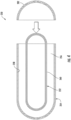
- the vacuum vessel 254 includes a removeable cap 282 (see e.g., FIG. 4 ).
- cryogenic tank 252 and the vacuum vessel 254 may be made of any suitable materials.
- one or both of the cryogenic tank 252 and the vacuum vessel 254 may be constructed of a composite material.
- one or both of the cryogenic tank 252 and the vacuum vessel 254 may be constructed of a metal material.
- the cryogenic fuel system 250 includes a suspension system 262 arranged within the vacuum space 256 so as to support the cryogenic tank 252 within the vacuum vessel 254 and to maintain the cryogenic tank 252 within the vacuum vessel 254 in a desired position.
- the suspension system 262 includes a plurality of roller elements 264 arranged within the vacuum space 256 and contacting the inner surface 258 of the vacuum vessel 254 and the outer surface 260 of the cryogenic tank 252.
- the roller elements 264 contact the inner surface 258 of the vacuum vessel 254 and the outer surface 260 of the cryogenic tank 252 at a plurality of different points along a longitudinal length of the cryogenic tank 252 so as to support the cryogenic tank 252 within the vacuum vessel 254, thereby maintaining the cryogenic tank 252 within the vacuum vessel 254 in a desired position (e.g., such as a centralized location in the vacuum vessel 254).
- the suspension system 262 may include roller elements 264 that provide both axial and radial suspension, e.g., in an axial direction A and a radial direction R, respectively.
- the suspension system 262 may provide suspension in the axial direction A using one or more axial suspension members 284 that can be placed at any suitable location along the cryogenic tank 252, such as at the front or back of the cryogenic tank 252.
- the axial suspension member(s) 284 may have a generally dome shape with one or more holes that receive a subset of the roller elements 264.
- the axial suspension members 284 may include one or more locking features 275 (e.g., protrusions, notches, etc.) that lock the axial suspension members 284 to the radial suspension members 268. Further, as shown in FIGS. 11A and 11B , the locking features 275 may be spaced circumferentially about the axial suspension members 284 so as to provide adequate locking.
- locking features 275 e.g., protrusions, notches, etc.
- the cryogenic tank 252 may be slidable with respect to the vacuum vessel 254 via the roller elements 264. Accordingly, in an embodiment, the removable cap 282 (see FIG. 4 ) of the vacuum vessel 254 can be easily opened such that the cryogenic tank 252 can be slid therein.
- the plurality of roller elements 264 may be connected together via one or more guide rails 266 ( FIG. 12 ) or one or more radial suspension members 268 or rod members (see e.g., FIGS. 5 , 7 , 8 , and 10 ). More specifically, as shown in FIGS. 5-10 , wherein the plurality of roller elements 264 are connected together via the radial suspension members 268, the roller elements 264 may be ball bearings 270 connected together via the radial suspension members 268. In such embodiments, as shown in FIGS. 5 and 7-8 , the radial suspension members 268 may extend through the ball bearings 270, as indicated by dotted lines in FIG. 7 .
- the plurality of roller elements 264 may be cylindrical roller elements 272, similar to wheels, connected together via the guide rails 266.
- a first guide rail 267 and a second guide rail 269 may be arranged on opposing sides of one or more rows of the cylindrical roller elements 272.
- first and second guide rails 267, 269 may include one or more flanges 271, 273, respectively, for securing the guide rails 266 to the inner surface 258 of the vacuum vessel 254 and the outer surface 260 of the cryogenic tank 252 (see FIG. 4 ).
- the plurality of roller elements 264 may be arranged into a plurality of rows 274 of roller elements 264.
- the plurality of rows 274 of roller elements 264 may be circumferentially spaced around the cryogenic tank 252 within the vacuum space 256.
- the suspension system 262 may also include at least one ring member 276 connecting the plurality of rows of roller elements 264 together. More particularly, in an embodiment, as shown, the suspension system 262 may include a first ring member 278 at a forward location of the cryogenic tank 252 and a second ring member 280 at an aft location of the cryogenic tank 252. It should be further understood that the ring members 276 described herein may be located at any other suitable location along a length of the cryogenic tank 252, such as at an intermediate location of the cryogenic tank 252. Thus, the ring members 276 are provided to maintain the arrangement of the roller elements 264 within the vacuum space 256 and to maintain the desired location of the cryogenic tank 252 within the vacuum vessel 254.
- the suspension system 262 may also include one or more insulation members 265 arranged between one or more (or each of) the roller elements 264.
- the insulation member(s) 265 are further configured to assist with suspending the cryogenic tank 252 within the vacuum vessel 254.
- FIG. 13 a flow diagram of an embodiment of a method 300 of assembling a cryogenic system according to the present disclosure is illustrated.
- the method 300 is described herein for the turbojet engine 100 described above.
- the disclosed method 300 may be used for any other engine or suitable cryogenic application, such as a superconducting generator, having any suitable configuration.
- FIG. 13 depicts steps performed in a particular order for purposes of illustration and discussion, the methods described herein are not limited to any particular order or arrangement.
- One skilled in the art, using the disclosures provided herein, will appreciate that various steps of the methods can be omitted, rearranged, combined and/or adapted in various ways.
- the method 300 includes securing a suspension system having a plurality of roller elements circumferentially around a cryogenic tank containing a liquid cryogen.
- the method 300 includes sliding the cryogenic tank into a vacuum vessel via the plurality of roller elements such that a radial space is created between an inner surface of the vacuum vessel and an outer surface of the cryogenic tank and the plurality of roller elements contact the inner surface of the vacuum vessel and the outer surface of the cryogenic tank.
- the method 300 includes creating a vacuum within the radial space, wherein the suspension system supports the cryogenic tank within the vacuum vessel and maintains the cryogenic tank within the vacuum vessel in a desired position.
- the method 300 may include opening the removable cap of the vacuum vessel prior to sliding the sliding the cryogenic tank into the vacuum vessel via the plurality of roller elements and subsequently closing the removable cap once the cryogenic tank is slid into place.
- the suspension system containing the roller elements are configured to assist with assembly and positioning of the cryogenic tank within the vacuum vessel.
- the method 300 of FIG. 13 may further include securing a radial suspension system having a plurality of roller elements circumferentially around the cryogenic tank. Further, the method 300 may include securing an axial suspension system having first and second axial suspension components and a plurality of roller elements axially with respect to the cryogenic tank. As such, the method 300 further includes assembling the radial suspension system together with the first axial suspension component and sliding the cryogenic tank into a vacuum vessel via the plurality of roller elements such that a space is created between the inner surface of the vacuum vessel and the outer surface of the cryogenic tank and the plurality of roller elements contact the inner surface of the vacuum vessel and the outer surface of the cryogenic tank.
- the method 300 may include locking the radial suspension to the first axial suspension component, assembling a second axial suspension component, and then locking the first and second axial components to the radial suspension system.
- the assembly can then be completed by capping the open dome region with a welded, bolted or adhesively joined cap.
- the method 300 may include creating a vacuum within the radial space, wherein the suspension system supports the cryogenic tank within the vacuum vessel and maintains the cryogenic tank within the vacuum vessel in a desired position.
- the aircraft 10 shown in FIG. 1 is an airplane, the embodiments described herein may also be applicable to other aircraft 10, including, for example, helicopters, unmanned aerial vehicles (UAV), and ship propulsion.
- the embodiments described herein may also be applicable to other applications in addition to turbojet engines, such as superconducting generators.
- the engines described herein are gas turbine engines, but the embodiments described herein also may be applicable to other engines.
- the engine 100 is an example of a power generator using cryogenic fuel, but such fuel may be used as a fuel for other power generators.
- the power generator may be a fuel cell (hydrogen fuel cell) where the hydrogen is provided to the fuel cell to generate electricity by reacting with air.
- Such power generators may be used in various applications, including stationary power generation systems (including both gas turbines and hydrogen fuel cells) and other vehicles beyond the aircraft 10 explicitly described herein, such as boats, ships, cars, trucks, and the like.
- cryogenic systems described herein may be used in superconducting machines, such as superconducting generators, that may be used in various applications such as renewable energy and MRI machines.
- a cryogenic system comprises a cryogenic tank containing a liquid cryogen, a vacuum vessel surrounding the cryogenic tank and providing a vacuum space between an inner surface of the vacuum vessel and an outer surface of the cryogenic tank, and a suspension system arranged within the vacuum space so as to support the cryogenic tank within the vacuum vessel and to maintain the cryogenic tank within the vacuum vessel in a desired position, the suspension system comprising a plurality of roller elements arranged within the vacuum space and contacting the inner surface of the vacuum vessel and the outer surface of the cryogenic tank.
- the one or more axial suspension members comprise one or more locking features configured to lock the one or more axial suspension members with respect to the one or more radial suspension members.
- the suspension system further comprises one or more insulation members arranged between one or more of the roller elements.
- cryogenic system of any preceding clauses, wherein the suspension system further comprises at least one ring member connecting the plurality of rows of roller elements together.
- cryogenic system of any preceding clauses, wherein the cryogenic tank is slidable with respect to the vacuum vessel.
- cryogenic system of any preceding clauses, wherein the cryogenic system is part of one of a turbojet engine or a superconducting generator.
- cryogenic tank and the vacuum vessel are each constructed of a composite material.
- a method of assembling a cryogenic system comprises securing a suspension system having a plurality of roller elements circumferentially around a cryogenic tank containing a liquid cryogen, sliding the cryogenic tank into a vacuum vessel via the plurality of roller elements such that a radial space is created between an inner surface of the vacuum vessel and an outer surface of the cryogenic tank and the plurality of roller elements contact the inner surface of the vacuum vessel and the outer surface of the cryogenic tank, and creating a vacuum within the radial space, wherein the suspension system supports the cryogenic tank within the vacuum vessel and maintains the cryogenic tank within the vacuum vessel in a desired position.
- the method of any preceding clause further comprises arranging the plurality of roller elements in an axial direction in the vacuum space via one or more axial suspension members and in a radial direction in the vacuum space via one or more radial suspension members and securing the one or more axial suspension members to the one or more radial suspension members via one or more locking features on the one or more axial suspension members.
- a cryogenic fuel system for a turbojet engine comprises a cryogenic tank containing a liquid cryogen fuel for the turbojet engine, a vacuum vessel surrounding the cryogenic tank and providing a vacuum space between an inner surface of the vacuum vessel and an outer surface of the cryogenic tank, and a plurality of roller elements arranged within the vacuum space and contacting the inner surface of the vacuum vessel and the outer surface of the cryogenic tank at a plurality of different points along a longitudinal length of the cryogenic tank so as to support the cryogenic tank within the vacuum vessel and maintain the cryogenic tank within the vacuum vessel in a desired position.
Abstract
A cryogenic system (250) includes a cryogenic tank (252) containing a liquid cryogen and a vacuum vessel (254) surrounding the cryogenic tank (252) and providing a vacuum space (256) between an inner surface (258) of the vacuum vessel (254) and an outer surface (260) of the cryogenic tank (252). The cryogenic system (250) further includes a suspension system (262) arranged within the vacuum space (256) so as to support the cryogenic tank (252) within the vacuum vessel (254) and to maintain the cryogenic tank (252) within the vacuum vessel (254) in a desired position. The suspension system (262) includes a plurality of roller elements (264) arranged within the vacuum space (256) and contacting the inner surface (258) of the vacuum vessel (254) and the outer surface (260) of the cryogenic tank (252).
Description
- This invention was made with government support under contract number 80NSSC19M0125 awarded by The National Aeronautics and Space Administration (NASA). The U.S. government may have certain rights in the invention.
- The present disclosure relates to cryogenic systems, and more particularly to cryogenic systems for turbine engines.
- The propulsion system for commercial aircraft typically includes one or more aircraft engines, such as turbofan jet engines. The turbofan jet engine(s) may be mounted to a respective one of the wings of the aircraft, such as in a suspended position beneath the wing using a pylon. These engines may be powered by aviation turbine fuel, which is typically a combustible hydrocarbon liquid fuel, such as a kerosene-type fuel, having a desired carbon number. The aviation turbine fuel is a relatively power-dense fuel that is relatively easy to transport and stays in a liquid phase through most ambient operating conditions for aircraft. Such fuel produces carbon dioxide upon combustion, and improvements to reduce such carbon dioxide emissions in commercial aircraft are desired.
- Furthermore, current approaches to cooling in conventional turbine engine applications use compressed air or conventional liquid jet fuel. Use of compressor air for cooling may lower efficiency of the engine system. Moreover, as mentioned, conventional liquid jet fuel produces carbon dioxide.
- Thus, certain turbofan jet engines have employed cryogenic liquid fuels, such as liquefied natural gas (LNG) or liquid hydrogen, which may be more environmentally friendly and cheaper than conventional liquid jet fuels.
- Accordingly, it is desirable to have aircraft systems propelled by turbofan jet engines that can be operated using cryogenic liquid fuels. Therefore, the present disclosure is directed to an improved cryogenic system for turbofan jet engines.
- A full and enabling disclosure of the present disclosure, including the best mode thereof, directed to one of ordinary skill in the art, is set forth in the specification, which makes reference to the appended figures, in which:
-
FIG. 1 is a schematic perspective view of an aircraft having an engine according to an embodiment of the present disclosure. -
FIG. 2 is a schematic, cross-sectional view, taken along line 2-2 inFIG. 1 , of a turbine engine that is used as a power generator for the aircraft shown inFIG. 1 . -
FIG. 3 is a schematic view of an embodiment of a fuel system according to the present disclosure. -
FIG. 4 is a side view of an embodiment of a cryogenic fuel system for an engine according to the present disclosure. -
FIG. 5 is a side view of an embodiment of a cryogenic fuel system for an engine according to the present disclosure, particularly illustrating a suspension system for the cryogenic fuel system having a plurality of roller elements with insulation arranged therebetween. -
FIG. 6 is a cross-sectional view of the cryogenic fuel system ofFIG. 5 along line 6-6. -
FIG. 7 is a side view of an embodiment of a row of roller elements for a radial suspension system for a cryogenic fuel system for an engine according to the present disclosure. -
FIG. 8 is a side view of another embodiment of a cryogenic fuel system for an engine according to the present disclosure, particularly illustrating a radial suspension system for the cryogenic fuel system having a plurality of roller elements. -
FIG. 9 is a cross-sectional view of the cryogenic fuel system ofFIG. 8 . -
FIG. 10 is a side view of another embodiment of a cryogenic fuel system for an engine according to the present disclosure, particularly illustrating a suspension system for the cryogenic fuel system having a plurality of roller elements that provide radial and axial suspension of a liquid fuel tank of the cryogenic fuel system. -
FIGS. 11A and 11B are front and side views of the cryogenic fuel system ofFIG. 10 . -
FIG. 12 is a perspective view of an embodiment of a plurality of roller elements for a suspension system for a cryogenic fuel system for an engine according to the present disclosure. -
FIG. 13 is a flow diagram of an embodiment of a method of assembling a cryogenic system according to the present disclosure. - Reference will now be made in detail to present embodiments of the disclosure, one or more examples of which are illustrated in the accompanying drawings. The detailed description uses numerical and letter designations to refer to features in the drawings. Like or similar designations in the drawings and description have been used to refer to like or similar parts of the disclosure.
- The word "exemplary" is used herein to mean "serving as an example, instance, or illustration." Any implementation described herein as "exemplary" is not necessarily to be construed as preferred or advantageous over other implementations. Additionally, unless specifically identified otherwise, all embodiments described herein should be considered exemplary.
- The singular forms "a", "an", and "the" include plural references unless the context clearly dictates otherwise.
- The term "turbomachine" refers to a machine including one or more compressors, a heat generating section (e.g., a combustion section), and one or more turbines that together generate a torque output.
- The term "gas turbine engine" refers to an engine having a turbomachine as all or a portion of its power source. Example gas turbine engines include turbofan engines, turboprop engines, turbojet engines, turboshaft engines, etc., as well as hybrid-electric versions of one or more of these engines.
- The term "combustion section" refers to any heat addition system for a turbomachine. For example, the term combustion section may refer to a section including one or more of a deflagrative combustion assembly, a rotating detonation combustion assembly, a pulse detonation combustion assembly, or other appropriate heat addition assembly. In certain example embodiments, the combustion section may include an annular combustor, a can combustor, a cannular combustor, a trapped vortex combustor (TVC), or other appropriate combustion system, or combinations thereof.
- The terms "low" and "high", or their respective comparative degrees (e.g., -er, where applicable), when used with a compressor, a turbine, a shaft, or spool components, etc. each refer to relative speeds within an engine unless otherwise specified. For example, a "low turbine" or "low speed turbine" defines a component configured to operate at a rotational speed, such as a maximum allowable rotational speed, lower than a "high turbine" or "high speed turbine" of the engine.
- The terms "forward" and "aft" refer to relative positions within a gas turbine engine or vehicle, and refer to the normal operational attitude of the gas turbine engine or vehicle. For example, with regard to a gas turbine engine, forward refers to a position closer to an engine inlet and aft refers to a position closer to an engine nozzle or exhaust.
- As used herein, the terms "axial" and "axially" refer to directions and orientations that extend substantially parallel to a centerline of the gas turbine engine. Moreover, the terms "radial" and "radially" refer to directions and orientations that extend substantially perpendicular to the centerline of the gas turbine engine. In addition, as used herein, the terms "circumferential" and "circumferentially" refer to directions and orientations that extend arcuately about the centerline of the gas turbine engine.
- The terms "coupled", "attached to", and the like refer to both direct coupling, fixing, or attaching, as well as indirect coupling, fixing, or attaching through one or more intermediate components or features, unless otherwise specified herein.
- As may be used herein, the terms "first", "second", "third" and so on may be used interchangeably to distinguish one component from another and are not intended to signify location or importance of the individual components.
- Approximating language, as used herein throughout the specification and claims, is applied to modify any quantitative representation that could permissibly vary without resulting in a change in the basic function to which it is related. Accordingly, a value modified by a term or terms, such as "about", "approximately", and "substantially", are not to be limited to the precise value specified. In at least some instances, the approximating language may correspond to the precision of an instrument for measuring the value, or the precision of the methods or machines for constructing or manufacturing the components and/or systems. For example, the approximating language may refer to being within a 1, 2, 4, 10, 15, or 20 percent margin. These approximating margins may apply to a single value, either or both endpoints defining numerical ranges, and/or the margin for ranges between endpoints.
- Here and throughout the specification and claims, range limitations are combined and interchanged, such ranges are identified and include all the sub-ranges contained therein unless context or language indicates otherwise. For example, all ranges disclosed herein are inclusive of the endpoints, and the endpoints are independently combinable with each other.
- Conventional cryogenic tanks require a suspension system in order to support the cryogen-containing tank from the outer vacuum vessel. Conventional suspension systems include suspension tubes or rods, which are common when both the cryogen-containing tank and the vacuum vessel are metallic. However, suspension/rods are more difficult to implement when either the cryogen-containing tank or the vacuum vessel is made of composite materials. For example, when the cryogen-containing tank and/or the vacuum vessel is made of composite materials, special suspension components have to be integrated within the winding of the composite tank and/or the composite vessel.
- Accordingly, the present disclosure is directed to an improved suspension system for a cryogenic system. In particular, the suspension system of the present disclosure supports a cryovessel (e.g., the inner cryogen-containing tank) of the cryogenic system with respect to the vacuum vessel (e.g., the outer vessel). In particular, the cryogen-containing tank may be a liquid hydrogen (LH2) tank or any other cryogenic tank (e.g., containing LHe, LN2, LO2, etc.) with dual walls. As such, the suspension system can be used in any cryogenic tank with a vacuum environment. More particularly, in an embodiment, the suspension system may include a plurality of roller elements (e.g., either spheres or wheels) arranged in a guide rail or connected together via suspension members to enable easy assembly and/or positioning of the cryogenic tank within the vacuum vessel. As such, in an embodiment, the suspension system provides a very low parasitic heat load and easy access to the inner vacuum vessel for service. For example, the roller elements are arranged in the radial space between the cryogen-containing tank and the vacuum vessel and can be mechanically anchored to the stiffeners of the vacuum vessel. Further, the suspension system results in a low boil-off solution since the roller elements of the system only make point contact with both the vacuum vessel and cryogen-containing tank. Moreover, the suspension system provides only point-to-point contact between the roller elements and the cryogenic tank and between the roller elements and the vacuum vessel, thereby providing a suspension system distributed along a length of a central axis the cryogenic tank. In addition, the suspension system having the roller elements described herein provides a system with increased dynamic stiffness and reduced vibration.
- Referring now to the drawings,
FIG. 1 illustrates a perspective view of anaircraft 10 that may implement various preferred embodiments. As shown, theaircraft 10 includes afuselage 12,wings 14 attached to thefuselage 12, and anempennage 16. Theaircraft 10 also includes a propulsion system that produces a propulsive thrust required to propel theaircraft 10 in flight, during taxiing operations, and the like. The propulsion system for theaircraft 10 shown inFIG. 1 includes a pair ofengines 100. In this embodiment, eachengine 100 is attached to one of thewings 14 by apylon 18 in an under-wing configuration. Although theengines 100 are shown attached to thewing 14 in an under-wing configuration inFIG. 1 , in other embodiments, theengines 100 may have alternative configurations and be coupled to other portions of theaircraft 10. For example, theengine 100 may additionally or alternatively include one or more aspects coupled to other parts of theaircraft 10, such as, for example, theempennage 16, and thefuselage 12. - As will be described further below with reference to
FIG. 2 , theengines 100 shown inFIG. 1 are each capable of selectively generating a propulsive thrust for theaircraft 10. The amount of propulsive thrust may be controlled at least in part based on a volume of fuel provided to theturbine engine 100 via a fuel system 200 (seeFIG. 3 ). In the embodiments discussed herein, the fuel is a cryogen fuel, such as liquid hydrogen fuel or liquid natural gas (LNG), that is stored in a liquid fuel tank 206 (seeFIG. 3 ) of thefuel system 200. In certain embodiments, at least a portion of theliquid fuel tank 206 may be located in each wing 14 (FIG. 1 ) and a portion of theliquid fuel tank 206 may be located in thefuselage 12 between thewings 14. Theliquid fuel tank 206, however, may be located at other suitable locations in thefuselage 12 or thewing 14. Theliquid fuel tank 206 may also be located entirely within thefuselage 12 or thewing 14. Theliquid fuel tank 206 may also be separate tanks instead of a single, unitary body, such as, for example, two tanks each located within acorresponding wing 14. - For the embodiment depicted, the power generator is an
engine 100 and, in particular, a high bypass turbofan engine. Theengine 100 may also be referred to as aturbofan engine 100 herein.FIG. 2 is a schematic, cross-sectional view of one of theengines 100 used in the propulsion system for theaircraft 10 shown inFIG. 1 . Theturbofan engine 100 has an axial direction A (extending parallel to alongitudinal centerline 101, shown for reference inFIG. 2 ), a radial direction R, and a circumferential direction. The circumferential direction (not depicted inFIG. 2 ) extends in a direction rotating about the axial direction A. Theturbofan engine 100 includes afan section 102 and aturbomachine 104 disposed downstream from thefan section 102. - The
turbomachine 104 depicted inFIG. 2 includes a tubularouter casing 106 that defines anannular inlet 108. Theouter casing 106 encases, in a serial flow relationship, a compressor section including a booster or low-pressure (LP)compressor 110 and a high-pressure (HP)compressor 112, acombustion section 114, a turbine section including a high-pressure (HP)turbine 116 and a low-pressure (LP)turbine 118, and a jetexhaust nozzle section 120. The compressor section, thecombustion section 114, and the turbine section together define at least in part a coreair flow path 121 extending from theannular inlet 108 to the jetexhaust nozzle section 120. Theturbofan engine 100 further includes one or more drive shafts. More specifically, theturbofan engine 100 includes a high-pressure (HP) shaft or aspool 122 drivingly connecting theHP turbine 116 to theHP compressor 112, and a low-pressure (LP) shaft or aspool 124 drivingly connecting theLP turbine 118 to theLP compressor 110. - The
fan section 102 shown inFIG. 2 includes afan 126 having a plurality offan blades 128 coupled to adisk 130 in a spaced-apart manner. Thefan blades 128 anddisk 130 are rotatable, together, about the longitudinal centerline (axis) 101 by theLP shaft 124. Thedisk 130 is covered by arotatable front hub 132 aerodynamically contoured to promote an airflow through the plurality offan blades 128. Further, an annular fan casing orouter nacelle 134 is provided, circumferentially surrounding thefan 126 and/or at least a portion of theturbomachine 104. Thenacelle 134 is supported relative to theturbomachine 104 by a plurality of circumferentially spaced outlet guide vanes 136. Adownstream section 138 of thenacelle 134 extends over an outer portion of theturbomachine 104, so as to define abypass airflow passage 140 therebetween. - It will be appreciated, however, that the
turbofan engine 100 discussed herein is provided by way of example only. In other embodiments, any other suitable engine may be utilized with aspects of the present disclosure. For example, in other embodiments, theturbofan engine 100 may be any other suitable gas turbine engine, such as a turboshaft engine, a turboprop engine, a turbojet engine, and the like. In such a manner, it will further be appreciated that, in other embodiments, the gas turbine engine may have other suitable configurations, such as other suitable numbers or arrangements of shafts, compressors, turbines, fans, etc. Further, although theturbofan engine 100 is shown as a direct drive, fixed-pitch turbofan engine 100, in other embodiments, a turbine engine may be a geared turbine engine (i.e., including a gearbox between thefan 126 and shaft driving the fan, such as the LP shaft 124), may be a variable pitch turbine engine (i.e., including afan 126 having a plurality offan blades 128 rotatable about their respective pitch axes), etc. Further, still, in alternative embodiments, aspects of the present disclosure may be incorporated into, or otherwise utilized with, any other type of engine, such as reciprocating engines, as discussed above. - Referring to
FIGS. 2 and3 , theturbofan engine 100 is operable with thefuel system 200 and receives a flow of fuel from thefuel system 200. As will be described further below, thefuel system 200 includes afuel delivery assembly 202 providing the fuel flow from theliquid fuel tank 206 to theturbofan engine 100, and, more specifically, to a fuel manifold (not shown) of thecombustion section 114 of theturbomachine 104 of theturbofan engine 100. - More particularly,
FIG. 3 illustrates a schematic view of thefuel system 200 according to an embodiment of the present disclosure that is configured to store the fuel for theengine 100 in theliquid fuel tank 206 and to deliver the fuel to theengine 100 via thefuel delivery assembly 202. In an embodiment, thefuel system 200 may be suitable for a vehicle having an engine 204 (e.g., the engine 100) in accordance with an exemplary embodiment of the present disclosure is provided. More specifically, for the exemplary embodiment ofFIG. 3 , the vehicle may be an aeronautical vehicle, such as theexemplary aircraft 10 ofFIG. 1 , and theengine 204 may be an aeronautical gas turbine engine, such as theexemplary engines 100 ofFIG. 1 and/or theexemplary turbofan engine 100 ofFIG. 2 . - It will be appreciated, however, that in other embodiments, the vehicle may be any other suitable land or aeronautical vehicle and the
engine 204 may be any other suitable engine mounted to or within the vehicle in any suitable manner. - The
exemplary fuel system 200 depicted is generally a hydrogen fuel system configured to store a hydrogen fuel and provide the hydrogen fuel to theengine 204. - For the embodiment shown, the
fuel system 200 generally includes a liquidcryogenic fuel tank 206 for holding a first portion of cryogenic fuel in a liquid phase. The liquidcryogenic fuel tank 206 may more specifically be configured to store the first portion of cryogenic fuel, such as hydrogen fuel, substantially completely in the liquid phase. For example, the liquidcryogenic fuel tank 206 may be configured to store the first portion at a temperature of about -253°C or less, and at a pressure greater than about one bar and less than about 10 bar, such as between about three bar and about five bar, or at other temperatures and pressures to maintain the cryogenic fuel substantially in the liquid phase. - It will be appreciated that as used herein, the term "substantially completely" as used to describe a phase of the cryogenic fuel refers to at least 99% by mass of the described portion of the cryogenic fuel being in the stated phase, or such as at least 97.5%, such as at least 95%, such as at least 92.5%, such as at least 90%, such as at least 85%, such as at least 75% by mass of the described portion of the cryogenic fuel being in the stated phase.
- The
fuel system 200 further includes a gaseouscryogenic fuel tank 208 configured to store a second portion of cryogenic fuel in a gaseous phase. The gaseouscryogenic fuel tank 208 may be configured to store the second portion of cryogenic fuel at an increased pressure so as to reduce a necessary size of the gaseouscryogenic fuel tank 208 within theaircraft 10. For example, in an embodiment, the gaseouscryogenic fuel tank 208 may be configured to store the second portion of cryogenic fuel at a pressure of at least about 100 bar, such as at least about 200 bar, such as at least about 400 bar, such as at least about 600 bar, such as at least about 700 bar, and up to about 1,000 bar. The gaseouscryogenic fuel tank 208 may be configured to store the second portion of the cryogenic fuel at a temperature within about 50°C of an ambient temperature, or between about -50°C and about 100°C. - It will be appreciated, that for the embodiment depicted, the gaseous
cryogenic fuel tank 208 is more specifically a plurality of gaseous cryogenic fuel tanks. In such embodiments, the plurality of gaseous cryogenic fuel tanks are configured to reduce an overall size and weight that would otherwise be needed to contain the desired volume of the second portion of cryogenic fuel in the gaseous phase at the desired pressures. - As will further be appreciated, a substantial portion of the total cryogenic fuel storage capacity of the
fuel system 200 is provided by the liquidcryogenic fuel tank 206. For example, in certain exemplary embodiments, thefuel system 200 defines a maximum fuel storage capacity. The liquidcryogenic fuel tank 206 may provide more than 50% of the maximum fuel storage capacity (in kilograms), with the remaining portion provided by the gaseouscryogenic fuel tank 208. For example, in certain exemplary aspects, the liquidcryogenic fuel tank 206 may provide at least about 60% of the maximum fuel storage capacity, such as at least about 70% of the maximum fuel storage capacity, such as at least about 80% of the maximum fuel storage capacity, such as up to about 98% of the maximum fuel storage capacity, such as up to about 95% of the maximum fuel storage capacity. The gaseouscryogenic fuel tank 208 may be configured to provide the remaining fuel storage capacity, such as at least about 2% of the maximum fuel storage capacity, such as at least about 5% of the maximum fuel storage capacity, such as at least about 10% of the maximum fuel storage capacity, such as at least about 15% of the maximum fuel storage capacity, such as at least about 20% of the maximum fuel storage capacity, such as up to 50% of the maximum fuel storage capacity, such as up to about 40% of the maximum fuel storage capacity. - Referring still to
FIG. 3 , thefuel system 200 further includes thefuel delivery assembly 202. Thefuel delivery assembly 202 generally includes a liquidcryogenic delivery assembly 212 in fluid communication with the liquidcryogenic fuel tank 206, a gaseouscryogenic delivery assembly 214 in fluid communication with the gaseouscryogenic fuel tank 208, and aregulator assembly 216 in fluid communication with both the liquidcryogenic delivery assembly 212 and the gaseouscryogenic delivery assembly 214 for providing cryogenic fuel to theengine 204. - The liquid
cryogenic delivery assembly 212 generally includes apump 218 and aheat exchanger 220 located downstream of thepump 218. Thepump 218 is configured to provide a flow of the first portion of cryogenic fuel in the liquid phase from the liquidcryogenic fuel tank 206 through the liquidcryogenic delivery assembly 212. Operation of thepump 218 may be increased or decreased to effectuate a change in a volume of the first portion of cryogenic fuel through the liquidcryogenic delivery assembly 212, and to theregulator assembly 216 andengine 204. Thepump 218 may be any suitable pump configured to provide a flow of liquid cryogenic fuel. For example, in certain exemplary aspects, thepump 218 may be configured as a cryogenic pump. - Still referring to
FIG. 3 , it will be appreciated that the liquidcryogenic fuel tank 206 may define a fixed volume, such that as the liquidcryogenic fuel tank 206 provides cryogenic fuel to thefuel system 200 substantially completely in the liquid phase, a volume of the liquid cryogenic fuel in the liquidcryogenic fuel tank 206 decreases, and the volume is made up by, e.g., gaseous cryogenic fuel. Further, during the normal course of storing the first portion of cryogenic fuel in the liquid phase, an amount of the first portion of cryogenic fuel may vaporize. - In order to prevent an internal pressure within the liquid
cryogenic fuel tank 206 from exceeding a desired pressure threshold, thefuel system 200 is configured to allow for a purging of gaseous cryogenic fuel from the liquidcryogenic fuel tank 206. More specifically, in an embodiment, thefuel delivery assembly 202 of thefuel system 200 includes a boil-offfuel assembly 222 configured to receive gaseous cryogenic fuel from the liquidcryogenic fuel tank 206. The boil-offfuel assembly 222 generally includes a boil-offcompressor 224 and a boil-off tank 226. The boil-off tank 226 is in fluid communication with the liquidcryogenic fuel tank 206 and is further in fluid communication with the gaseouscryogenic delivery assembly 214. - During operation, gaseous fuel from the liquid
cryogenic fuel tank 206 may be received in the boil-offfuel assembly 222, may be compressed by the boil-offcompressor 224 and provided to the boil-off tank 226. The boil-off tank 226 may be configured to store the gaseous cryogenic fuel at a lower pressure than the pressure of the second portion of the cryogenic fuel within the gaseouscryogenic fuel tank 208. - Referring again to the gaseous
cryogenic delivery assembly 214, the gaseouscryogenic delivery assembly 214 generally includes a three-way boil-offvalve 228 defining afirst input 230, asecond input 232, and anoutput 234. Thefirst input 230 may be in fluid communication with the gaseouscryogenic fuel tank 208 for receiving a flow of the second portion of cryogenic fuel in the gaseous phase from the gaseouscryogenic fuel tank 208. For the embodiment depicted, thesecond input 232 is in fluid communication with the boil-offfuel assembly 222 for receiving a flow of gaseous cryogenic fuel from, e.g., the boil-off tank 226 of the boil-offfuel assembly 222. The three-way boil-offvalve 228 may be configured to combine and/or alternate the flows from thefirst input 230 and thesecond input 232 to a single flow of gaseous cryogenic fuel through theoutput 234. For the embodiment shown, the three-way boil-offvalve 228 is an active valve, such that an amount of gaseous cryogenic fuel provided from thefirst input 230, as compared to the amount of gaseous cryogenic fuel provided from thesecond input 232, to theoutput 234 may be actively controlled. In other exemplary embodiments, the three-way boil-offvalve 228 may be a passive valve. - The
fuel system 200 may also include a gaseous hydrogen delivery assembly flow regulator 236 ("GHDA flow regulator 236"). TheGHDA flow regulator 236 may be configured as an actively controlled variable throughput valve configured to provide a variable throughput ranging from 0% (e.g., a completely closed off position) to 100% (e.g., a completely open position), as well as a number of intermediate throughput values therebetween. As briefly mentioned, theregulator assembly 216 is in fluid communication with both the liquidcryogenic delivery assembly 212 and the gaseouscryogenic delivery assembly 214 for providing gaseous cryogenic fuel to theengine 204. - Moreover, and still referring to
FIG. 3 , theregulator assembly 216 includes a three-way regulator valve 238. The three-way regulator valve 238 defines afirst input 240, asecond input 242, and anoutput 244. Thefirst input 240 may be in fluid communication with the gaseouscryogenic delivery assembly 214 for receiving a flow of the second portion of cryogenic fuel in the gaseous phase from the gaseous cryogenic fuel tank 208 (and, e.g., the boil-off fuel assembly 222). Thesecond input 242 is in fluid communication with the liquidcryogenic delivery assembly 212 for receiving a flow of the first portion of the cryogenic fuel in the gaseous phase from the liquid cryogenic fuel tank 206 (vaporized using, e.g., the heat exchanger 220). The three-way regulator value 238 may be configured to combine and/or alternate the flows from thefirst input 240 and thesecond input 242 to a single flow of gaseous cryogenic through theoutput 244. For the embodiment shown, the three-way regulator value 238 is an active three-way regulator value, such that an amount of gaseous cryogenic fuel provided from thefirst input 240, as compared to the amount of gaseous cryogenic fuel provided from thesecond input 242, to theoutput 244 may be actively controlled. In other exemplary embodiments, the three-way regulator value 238 may be a passive valve. - For the embodiment shown, the
regulator assembly 216 further includes a regulator assembly flow regulator 245 ("RA flow regulator 245") and aflowmeter 248. TheRA flow regulator 245 may be configured as an actively controlled variable throughput valve configured to provide a variable throughput ranging from 0% (e.g., a completely closed off position) to 100% (e.g., a completely open position), as well as a number of intermediate throughput values therebetween. - As mentioned, the liquid fuel tank(s) 206 of the
fuel system 200 contain a liquid cryogenic fuel. Thus, the fuel must be maintained at cryogenic temperatures such that the fuel remains in a substantially completely liquid phase. In order to maintain such temperatures, the liquid fuel tank(s) 206 are encompassed by a vacuum vessel that creates a vacuum space between the liquid fuel tank(s) 206 and the vacuum vessel. Furthermore, as mentioned, the liquid fuel tank(s) 206 requires a suspension system in order to support the liquid fuel tank(s) 206 within the vacuum vessel. Accordingly, the present disclosure is directed to an improved suspension system for a cryogenic fuel system. In particular, the cryogen-containing liquid fuel tank(s) 206 may be a liquid hydrogen (LH2) tank or any other cryogenic tank (e.g., containing LHe, LN2, LO2, etc.) with dual walls. As such, the suspension system described herein can be used in any cryogenic tank with a vacuum environment. - More particularly, in an embodiment, as shown in
FIG. 4 , acryogenic fuel system 250 according to the present disclosure is illustrated. As shown, thecryogenic fuel system 250 includes a cryogenic tank 252 (such as liquid fuel tank(s) 206) containing a liquid cryogen and avacuum vessel 254 surrounding thecryogenic tank 252. Thus, as shown, thevacuum vessel 254 provides avacuum space 256 between aninner surface 258 of thevacuum vessel 254 and anouter surface 260 of thecryogenic tank 252. In the illustrated embodiment, thevacuum vessel 254 includes a removeable cap 282 (see e.g.,FIG. 4 ). - In further embodiments, the
cryogenic tank 252 and thevacuum vessel 254 may be made of any suitable materials. For example, in an embodiment, one or both of thecryogenic tank 252 and thevacuum vessel 254 may be constructed of a composite material. In alternative embodiments, one or both of thecryogenic tank 252 and thevacuum vessel 254 may be constructed of a metal material. - Moreover, as shown generally in
FIGS. 5-12 , thecryogenic fuel system 250 includes asuspension system 262 arranged within thevacuum space 256 so as to support thecryogenic tank 252 within thevacuum vessel 254 and to maintain thecryogenic tank 252 within thevacuum vessel 254 in a desired position. Further, in an embodiment, as shown particularly inFIGS. 5 ,8 , and10 , thesuspension system 262 includes a plurality of roller elements 264 arranged within thevacuum space 256 and contacting theinner surface 258 of thevacuum vessel 254 and theouter surface 260 of thecryogenic tank 252. Thus, the roller elements 264 contact theinner surface 258 of thevacuum vessel 254 and theouter surface 260 of thecryogenic tank 252 at a plurality of different points along a longitudinal length of thecryogenic tank 252 so as to support thecryogenic tank 252 within thevacuum vessel 254, thereby maintaining thecryogenic tank 252 within thevacuum vessel 254 in a desired position (e.g., such as a centralized location in the vacuum vessel 254). - In particular embodiments, as shown in
FIGS. 5 ,10, 11A, and 11B , thesuspension system 262 may include roller elements 264 that provide both axial and radial suspension, e.g., in an axial direction A and a radial direction R, respectively. For example, as shown particularly inFIGS. 5 ,11A, and 11B , thesuspension system 262 may provide suspension in the axial direction A using one or moreaxial suspension members 284 that can be placed at any suitable location along thecryogenic tank 252, such as at the front or back of thecryogenic tank 252. In such embodiments, the axial suspension member(s) 284 may have a generally dome shape with one or more holes that receive a subset of the roller elements 264. Moreover, as shown inFIGS. 5 ,11A, and 11B , theaxial suspension members 284 may include one or more locking features 275 (e.g., protrusions, notches, etc.) that lock theaxial suspension members 284 to theradial suspension members 268. Further, as shown inFIGS. 11A and 11B , the locking features 275 may be spaced circumferentially about theaxial suspension members 284 so as to provide adequate locking. - Furthermore, in certain embodiments, the
cryogenic tank 252 may be slidable with respect to thevacuum vessel 254 via the roller elements 264. Accordingly, in an embodiment, the removable cap 282 (seeFIG. 4 ) of thevacuum vessel 254 can be easily opened such that thecryogenic tank 252 can be slid therein. - In an embodiment, for example, as shown in
FIGS. 5-12 , the plurality of roller elements 264 may be connected together via one or more guide rails 266 (FIG. 12 ) or one or moreradial suspension members 268 or rod members (see e.g.,FIGS. 5 ,7 ,8 , and10 ). More specifically, as shown inFIGS. 5-10 , wherein the plurality of roller elements 264 are connected together via theradial suspension members 268, the roller elements 264 may be ball bearings 270 connected together via theradial suspension members 268. In such embodiments, as shown inFIGS. 5 and7-8 , theradial suspension members 268 may extend through the ball bearings 270, as indicated by dotted lines inFIG. 7 . - In further embodiments, as shown in
FIG. 12 , wherein the plurality of roller elements 264 are connected together via theguide rails 266, the plurality of roller elements 264 may be cylindrical roller elements 272, similar to wheels, connected together via the guide rails 266. Further, in an embodiment, as shown inFIG. 12 , afirst guide rail 267 and asecond guide rail 269 may be arranged on opposing sides of one or more rows of the cylindrical roller elements 272. - In such embodiments, the first and
second guide rails more flanges guide rails 266 to theinner surface 258 of thevacuum vessel 254 and theouter surface 260 of the cryogenic tank 252 (seeFIG. 4 ). - Furthermore, in an embodiment, as shown in
FIGS. 5 ,8 , and10 , the plurality of roller elements 264 may be arranged into a plurality ofrows 274 of roller elements 264. Thus, in such embodiments, as shown inFIGS. 6 ,9 ,11A, and 11B , the plurality ofrows 274 of roller elements 264 may be circumferentially spaced around thecryogenic tank 252 within thevacuum space 256. - In additional embodiments, as shown in
FIGS. 8 and 9 , thesuspension system 262 may also include at least onering member 276 connecting the plurality of rows of roller elements 264 together. More particularly, in an embodiment, as shown, thesuspension system 262 may include a first ring member 278 at a forward location of thecryogenic tank 252 and a second ring member 280 at an aft location of thecryogenic tank 252. It should be further understood that thering members 276 described herein may be located at any other suitable location along a length of thecryogenic tank 252, such as at an intermediate location of thecryogenic tank 252. Thus, thering members 276 are provided to maintain the arrangement of the roller elements 264 within thevacuum space 256 and to maintain the desired location of thecryogenic tank 252 within thevacuum vessel 254. - Referring particularly to
FIGS. 5 and 6 , thesuspension system 262 may also include one ormore insulation members 265 arranged between one or more (or each of) the roller elements 264. Thus, the insulation member(s) 265 are further configured to assist with suspending thecryogenic tank 252 within thevacuum vessel 254. - Referring now to
FIG. 13 , a flow diagram of an embodiment of amethod 300 of assembling a cryogenic system according to the present disclosure is illustrated. In general, themethod 300 is described herein for theturbojet engine 100 described above. However, it should be appreciated that the disclosedmethod 300 may be used for any other engine or suitable cryogenic application, such as a superconducting generator, having any suitable configuration. In addition, althoughFIG. 13 depicts steps performed in a particular order for purposes of illustration and discussion, the methods described herein are not limited to any particular order or arrangement. One skilled in the art, using the disclosures provided herein, will appreciate that various steps of the methods can be omitted, rearranged, combined and/or adapted in various ways. - As shown at (302), the
method 300 includes securing a suspension system having a plurality of roller elements circumferentially around a cryogenic tank containing a liquid cryogen. As shown at (304), themethod 300 includes sliding the cryogenic tank into a vacuum vessel via the plurality of roller elements such that a radial space is created between an inner surface of the vacuum vessel and an outer surface of the cryogenic tank and the plurality of roller elements contact the inner surface of the vacuum vessel and the outer surface of the cryogenic tank. As shown at (306), themethod 300 includes creating a vacuum within the radial space, wherein the suspension system supports the cryogenic tank within the vacuum vessel and maintains the cryogenic tank within the vacuum vessel in a desired position. - In particular embodiments, the
method 300 may include opening the removable cap of the vacuum vessel prior to sliding the sliding the cryogenic tank into the vacuum vessel via the plurality of roller elements and subsequently closing the removable cap once the cryogenic tank is slid into place. In such embodiments, the suspension system containing the roller elements are configured to assist with assembly and positioning of the cryogenic tank within the vacuum vessel. - In particular embodiments, the
method 300 ofFIG. 13 may further include securing a radial suspension system having a plurality of roller elements circumferentially around the cryogenic tank. Further, themethod 300 may include securing an axial suspension system having first and second axial suspension components and a plurality of roller elements axially with respect to the cryogenic tank. As such, themethod 300 further includes assembling the radial suspension system together with the first axial suspension component and sliding the cryogenic tank into a vacuum vessel via the plurality of roller elements such that a space is created between the inner surface of the vacuum vessel and the outer surface of the cryogenic tank and the plurality of roller elements contact the inner surface of the vacuum vessel and the outer surface of the cryogenic tank. Moreover, themethod 300 may include locking the radial suspension to the first axial suspension component, assembling a second axial suspension component, and then locking the first and second axial components to the radial suspension system. The assembly can then be completed by capping the open dome region with a welded, bolted or adhesively joined cap. Subsequently, themethod 300 may include creating a vacuum within the radial space, wherein the suspension system supports the cryogenic tank within the vacuum vessel and maintains the cryogenic tank within the vacuum vessel in a desired position. - Although the
aircraft 10 shown inFIG. 1 is an airplane, the embodiments described herein may also be applicable toother aircraft 10, including, for example, helicopters, unmanned aerial vehicles (UAV), and ship propulsion. In addition, the embodiments described herein may also be applicable to other applications in addition to turbojet engines, such as superconducting generators. The engines described herein are gas turbine engines, but the embodiments described herein also may be applicable to other engines. Further, theengine 100 is an example of a power generator using cryogenic fuel, but such fuel may be used as a fuel for other power generators. For example, the power generator may be a fuel cell (hydrogen fuel cell) where the hydrogen is provided to the fuel cell to generate electricity by reacting with air. Such power generators may be used in various applications, including stationary power generation systems (including both gas turbines and hydrogen fuel cells) and other vehicles beyond theaircraft 10 explicitly described herein, such as boats, ships, cars, trucks, and the like. Furthermore, the cryogenic systems described herein may be used in superconducting machines, such as superconducting generators, that may be used in various applications such as renewable energy and MRI machines. - Further aspects are provided by the subject matter of the following clauses:
- A cryogenic system comprises a cryogenic tank containing a liquid cryogen, a vacuum vessel surrounding the cryogenic tank and providing a vacuum space between an inner surface of the vacuum vessel and an outer surface of the cryogenic tank, and a suspension system arranged within the vacuum space so as to support the cryogenic tank within the vacuum vessel and to maintain the cryogenic tank within the vacuum vessel in a desired position, the suspension system comprising a plurality of roller elements arranged within the vacuum space and contacting the inner surface of the vacuum vessel and the outer surface of the cryogenic tank.
- The cryogenic system of the preceding clause, wherein the plurality of roller elements of the suspension system are arranged in a radial direction and an axial direction in the vacuum space.
- The cryogenic system of any preceding clauses, wherein the plurality of roller elements arranged in the axial direction in the vacuum space are held in place via one or more axial suspension members and the plurality of roller elements arranged in the radial direction in the vacuum space are held in place via one or more radial suspension members.
- The cryogenic system of any preceding clauses, wherein the one or more axial suspension members comprise one or more locking features configured to lock the one or more axial suspension members with respect to the one or more radial suspension members.
- The cryogenic system of any preceding clauses, wherein the plurality of roller elements are connected together via one or more guide rails, and wherein the plurality of roller elements comprise cylindrical roller elements connected together via the one or more guide rails.
- The cryogenic system of any preceding clauses, wherein the plurality of roller elements comprise ball bearings.
- The cryogenic system of any preceding clauses, wherein the one or more radial suspension members extend through the ball bearings.
- The cryogenic system of any preceding clauses, wherein the suspension system further comprises one or more insulation members arranged between one or more of the roller elements.
- The cryogenic system of any preceding clauses, wherein the plurality of roller elements are arranged into a plurality of rows of roller elements circumferentially spaced around the cryogenic tank within the vacuum space.
- The cryogenic system of any preceding clauses, wherein the suspension system further comprises at least one ring member connecting the plurality of rows of roller elements together.
- The cryogenic system of any preceding clauses, wherein the cryogenic tank is slidable with respect to the vacuum vessel.
- The cryogenic system of any preceding clauses, wherein the vacuum vessel comprises a removable cap.
- The cryogenic system of any preceding clauses, wherein the cryogenic system is part of one of a turbojet engine or a superconducting generator.
- The cryogenic system of any preceding clauses, wherein the cryogenic tank and the vacuum vessel are each constructed of a composite material.
- A method of assembling a cryogenic system, the method comprises securing a suspension system having a plurality of roller elements circumferentially around a cryogenic tank containing a liquid cryogen, sliding the cryogenic tank into a vacuum vessel via the plurality of roller elements such that a radial space is created between an inner surface of the vacuum vessel and an outer surface of the cryogenic tank and the plurality of roller elements contact the inner surface of the vacuum vessel and the outer surface of the cryogenic tank, and creating a vacuum within the radial space, wherein the suspension system supports the cryogenic tank within the vacuum vessel and maintains the cryogenic tank within the vacuum vessel in a desired position.
- The method of any preceding clause, further comprising opening a removable cap of the vacuum vessel prior to sliding the sliding the cryogenic tank into the vacuum vessel via the plurality of roller elements and subsequently closing the removable cap once the cryogenic tank is slid into place.
- The method of any preceding clause, further comprising connecting the plurality of roller elements together via one or more guide rails, wherein the plurality of roller elements comprise cylindrical roller elements connected together via the one or more guide rails.
- The method of any preceding clause, further comprising connecting the plurality of roller elements together via one or more radial suspension members, wherein the plurality of roller elements comprise ball bearings connected together via the one or more radial suspension members.
- The method of any preceding clause, further comprises arranging the plurality of roller elements in an axial direction in the vacuum space via one or more axial suspension members and in a radial direction in the vacuum space via one or more radial suspension members and securing the one or more axial suspension members to the one or more radial suspension members via one or more locking features on the one or more axial suspension members.
- A cryogenic fuel system for a turbojet engine, the cryogenic fuel system comprises a cryogenic tank containing a liquid cryogen fuel for the turbojet engine, a vacuum vessel surrounding the cryogenic tank and providing a vacuum space between an inner surface of the vacuum vessel and an outer surface of the cryogenic tank, and a plurality of roller elements arranged within the vacuum space and contacting the inner surface of the vacuum vessel and the outer surface of the cryogenic tank at a plurality of different points along a longitudinal length of the cryogenic tank so as to support the cryogenic tank within the vacuum vessel and maintain the cryogenic tank within the vacuum vessel in a desired position.
- This written description uses examples to disclose the present disclosure, including the best mode, and also to enable any person skilled in the art to practice the disclosure, including making and using any devices or systems and performing any incorporated methods. The patentable scope of the disclosure is defined by the claims, and may include other examples that occur to those skilled in the art. Such other examples are intended to be within the scope of the claims if they include structural elements that do not differ from the literal language of the claims, or if they include equivalent structural elements with insubstantial differences from the literal languages of the claims.
Claims (15)
- A cryogenic system (250), comprising:a cryogenic tank (252) containing a liquid cryogen;a vacuum vessel (254) surrounding the cryogenic tank (252) and providing a vacuum space (256) between an inner surface (258) of the vacuum vessel (254) and an outer surface (260) of the cryogenic tank (252); anda suspension system (262) arranged within the vacuum space (256) so as to support the cryogenic tank (252) within the vacuum vessel (254) and to maintain the cryogenic tank (252) within the vacuum vessel (254) in a desired position, the suspension system (262) comprising a plurality of roller elements (264) arranged within the vacuum space (256) and contacting the inner surface (258) of the vacuum vessel (254) and the outer surface (260) of the cryogenic tank (252).
- The cryogenic system (250) of claim 1, wherein the plurality of roller elements (264) of the suspension system (262) are arranged in a radial direction and an axial direction in the vacuum space (256).
- The cryogenic system (250) of claim 2, wherein the plurality of roller elements (264) arranged in the axial direction in the vacuum space (256) are held in place via one or more axial suspension members (284) and the plurality of roller elements (264) arranged in the radial direction in the vacuum space (256) are held in place via one or more radial suspension members.
- The cryogenic system (250) of claim 3, wherein the one or more axial suspension members (284) comprise one or more locking features (275) configured to lock the one or more axial suspension members (284) with respect to the one or more radial suspension members (268).
- The cryogenic system (250) of any preceding claim, wherein the plurality of roller elements (264) are connected together via one or more guide rails (266), and wherein the plurality of roller elements (264) comprise cylindrical roller elements (272) connected together via the one or more guide rails (266).
- The cryogenic system (250) of any preceding claim, wherein the plurality of roller elements (264) comprise ball bearings (270).
- The cryogenic system (250) of claim 6, wherein the one or more radial suspension members (268) extend through the ball bearings (270).
- The cryogenic system (250) of any of the preceding claims, wherein the suspension system (262) further comprises one or more insulation members (265) arranged between one or more of the roller elements.
- The cryogenic system (250) of any of the preceding claims, wherein the plurality of roller elements (264) are arranged into a plurality of rows (274) of roller elements circumferentially spaced around the cryogenic tank (252) within the vacuum space (256).
- The cryogenic system (250) of claim 9, wherein the suspension system (262) further comprises at least one ring member connecting the plurality of rows of roller elements together.
- The cryogenic system (250) of any of the preceding claims, wherein the cryogenic tank (252) is slidable with respect to the vacuum vessel (254).
- The cryogenic system (250) of any of the preceding claims, wherein the vacuum vessel (254) comprises a removable cap.
- The cryogenic system (250) of any of the preceding claims, wherein the cryogenic system (250) is part of one of a turbojet engine or a superconducting generator.
- The cryogenic system (250) of any of the preceding claims, wherein the cryogenic tank (252) and the vacuum vessel (254) are each constructed of a composite material.
- A method (300) of assembling a cryogenic system (250), the method (300) comprising:securing a suspension system (262) having a plurality of roller elements (264) circumferentially around a cryogenic tank (252) containing a liquid cryogen;sliding the cryogenic tank (252) into a vacuum vessel (254) via the plurality of roller elements (264) such that a radial space is created between an inner surface (258) of the vacuum vessel (254) and an outer surface (260) of the cryogenic tank (252) and the plurality of roller elements (264) contact the inner surface (258) of the vacuum vessel (254) and the outer surface (260) of the cryogenic tank (252); and creating a vacuum within the radial space, wherein the suspension system (262) supports the cryogenic tank (252) within the vacuum vessel (254) and maintains the cryogenic tank (252) within the vacuum vessel (254) in a desired position.
Applications Claiming Priority (1)
| Application Number | Priority Date | Filing Date | Title |
|---|---|---|---|
| US17/883,895 US20240052976A1 (en) | 2022-08-09 | 2022-08-09 | Suspension system for a cryogenic tank |
Publications (1)
| Publication Number | Publication Date |
|---|---|
| EP4321792A1 true EP4321792A1 (en) | 2024-02-14 |
Family
ID=86185073
Family Applications (1)
| Application Number | Title | Priority Date | Filing Date |
|---|---|---|---|
| EP23169394.6A Pending EP4321792A1 (en) | 2022-08-09 | 2023-04-24 | Suspension system for a cryogenic tank |
Country Status (3)
| Country | Link |
|---|---|
| US (1) | US20240052976A1 (en) |
| EP (1) | EP4321792A1 (en) |
| CN (1) | CN117588680A (en) |
Citations (7)
| Publication number | Priority date | Publication date | Assignee | Title |
|---|---|---|---|---|
| US3043466A (en) * | 1961-07-13 | 1962-07-10 | Beudix Corp | Containers for cryogenic liquids and gases |
| JPS5260420A (en) * | 1975-11-14 | 1977-05-18 | Hitachi Ltd | Load supporting apparatus for ultra low-temperature vessel |
| EP0090334B1 (en) * | 1982-03-29 | 1986-11-12 | Union Carbide Corporation | Improved fiberglass insulation for mobile cryogenic tankage |
| JPH0712295A (en) * | 1993-06-25 | 1995-01-17 | Mitsubishi Heavy Ind Ltd | Inner chamber swing prevented supporting structure for double structural tank with heat insulation |
| AT501732A4 (en) * | 2005-03-15 | 2006-11-15 | Austrian Aerospace Gmbh | SUSPENSION FOR VACUUM-INSULATED DEEP-CLEAR CONSTRUCTION UNITS |
| US20090032539A1 (en) * | 2006-05-10 | 2009-02-05 | Siemens Magnet Technology Limited | Suspension Assembly For Mechanically Retaining a First Article by Bracing it Against a Second Article |
| GB2587556A (en) * | 2018-10-15 | 2021-03-31 | Gkn Aerospace Services Ltd | Apparatus |
-
2022
- 2022-08-09 US US17/883,895 patent/US20240052976A1/en active Pending
-
2023
- 2023-04-24 EP EP23169394.6A patent/EP4321792A1/en active Pending
- 2023-06-07 CN CN202310669016.0A patent/CN117588680A/en active Pending
Patent Citations (7)
| Publication number | Priority date | Publication date | Assignee | Title |
|---|---|---|---|---|
| US3043466A (en) * | 1961-07-13 | 1962-07-10 | Beudix Corp | Containers for cryogenic liquids and gases |
| JPS5260420A (en) * | 1975-11-14 | 1977-05-18 | Hitachi Ltd | Load supporting apparatus for ultra low-temperature vessel |
| EP0090334B1 (en) * | 1982-03-29 | 1986-11-12 | Union Carbide Corporation | Improved fiberglass insulation for mobile cryogenic tankage |
| JPH0712295A (en) * | 1993-06-25 | 1995-01-17 | Mitsubishi Heavy Ind Ltd | Inner chamber swing prevented supporting structure for double structural tank with heat insulation |
| AT501732A4 (en) * | 2005-03-15 | 2006-11-15 | Austrian Aerospace Gmbh | SUSPENSION FOR VACUUM-INSULATED DEEP-CLEAR CONSTRUCTION UNITS |
| US20090032539A1 (en) * | 2006-05-10 | 2009-02-05 | Siemens Magnet Technology Limited | Suspension Assembly For Mechanically Retaining a First Article by Bracing it Against a Second Article |
| GB2587556A (en) * | 2018-10-15 | 2021-03-31 | Gkn Aerospace Services Ltd | Apparatus |
Also Published As
| Publication number | Publication date |
|---|---|
| US20240052976A1 (en) | 2024-02-15 |
| CN117588680A (en) | 2024-02-23 |
Similar Documents
| Publication | Publication Date | Title |
|---|---|---|
| CN109278997B (en) | Operation of vertical takeoff and landing aircraft | |
| KR20220002857A (en) | Aircraft prime mover systems, how they work and how to use them | |
| US20150337730A1 (en) | Turbine engine assemblies | |
| JP6018065B2 (en) | Dual fuel aircraft system and method for operating the same | |
| US20130192246A1 (en) | Dual fuel aircraft engine control system and method for operating same | |
| EP2938711A2 (en) | Cryogenic fuel compositions and dual fuel aircraft system | |
| WO2014105331A1 (en) | Turbine engine assembly and dual fuel aircraft system | |
| EP2721272A1 (en) | Aircraft engine fuel system and method of operating the same | |
| EP2938917A1 (en) | Method for managing lng boil-off and lng -off management assembly | |
| GB2587556A (en) | Apparatus | |
| EP4321792A1 (en) | Suspension system for a cryogenic tank | |
| US20230122350A1 (en) | Hydrogen fuel system | |
| GB2587560A (en) | Apparatus | |
| US20240110509A1 (en) | Heat exchanger for a gas turbine engine | |
| EP4276290A1 (en) | Purge system for a hydrogen fuel system | |
| US20230175435A1 (en) | Combustor size rating for a gas turbine engine using hydrogen fuel | |
| US20230411646A1 (en) | Fuel cell power system for a vehicle | |
| US20240110524A1 (en) | Hydrogen fuel system for a vehicle | |
| US20230303238A1 (en) | Rotating airfoil assembly | |
| US20230219681A1 (en) | Rotating airfoil assembly with opening formed therein to eject or to draw air | |
| GB2587557A (en) | Apparatus | |
| GB2587558A (en) | Apparatus | |
| GB2587559A (en) | Apparatus | |
| Laruelle et al. | Systems Challenges for Hypersonic Vehicles |
Legal Events
| Date | Code | Title | Description |
|---|---|---|---|
| PUAI | Public reference made under article 153(3) epc to a published international application that has entered the european phase |
Free format text: ORIGINAL CODE: 0009012 |
|
| STAA | Information on the status of an ep patent application or granted ep patent |
Free format text: STATUS: THE APPLICATION HAS BEEN PUBLISHED |
|
| AK | Designated contracting states |
Kind code of ref document: A1 Designated state(s): AL AT BE BG CH CY CZ DE DK EE ES FI FR GB GR HR HU IE IS IT LI LT LU LV MC ME MK MT NL NO PL PT RO RS SE SI SK SM TR |