EP4321488A1 - Electrodeionization system and control method for electrodeionization system - Google Patents
Electrodeionization system and control method for electrodeionization system Download PDFInfo
- Publication number
- EP4321488A1 EP4321488A1 EP22784460.2A EP22784460A EP4321488A1 EP 4321488 A1 EP4321488 A1 EP 4321488A1 EP 22784460 A EP22784460 A EP 22784460A EP 4321488 A1 EP4321488 A1 EP 4321488A1
- Authority
- EP
- European Patent Office
- Prior art keywords
- flow rate
- electrodeionization
- water
- concentrated water
- sub
- Prior art date
- Legal status (The legal status is an assumption and is not a legal conclusion. Google has not performed a legal analysis and makes no representation as to the accuracy of the status listed.)
- Pending
Links
Images
Classifications
-
- C—CHEMISTRY; METALLURGY
- C02—TREATMENT OF WATER, WASTE WATER, SEWAGE, OR SLUDGE
- C02F—TREATMENT OF WATER, WASTE WATER, SEWAGE, OR SLUDGE
- C02F9/00—Multistage treatment of water, waste water or sewage
-
- B—PERFORMING OPERATIONS; TRANSPORTING
- B01—PHYSICAL OR CHEMICAL PROCESSES OR APPARATUS IN GENERAL
- B01D—SEPARATION
- B01D61/00—Processes of separation using semi-permeable membranes, e.g. dialysis, osmosis or ultrafiltration; Apparatus, accessories or auxiliary operations specially adapted therefor
- B01D61/42—Electrodialysis; Electro-osmosis ; Electro-ultrafiltration; Membrane capacitive deionization
- B01D61/44—Ion-selective electrodialysis
-
- B—PERFORMING OPERATIONS; TRANSPORTING
- B01—PHYSICAL OR CHEMICAL PROCESSES OR APPARATUS IN GENERAL
- B01D—SEPARATION
- B01D61/00—Processes of separation using semi-permeable membranes, e.g. dialysis, osmosis or ultrafiltration; Apparatus, accessories or auxiliary operations specially adapted therefor
- B01D61/42—Electrodialysis; Electro-osmosis ; Electro-ultrafiltration; Membrane capacitive deionization
- B01D61/44—Ion-selective electrodialysis
- B01D61/46—Apparatus therefor
- B01D61/48—Apparatus therefor having one or more compartments filled with ion-exchange material, e.g. electrodeionisation
- B01D61/485—Specific features relating to the ion-exchange material
-
- B—PERFORMING OPERATIONS; TRANSPORTING
- B01—PHYSICAL OR CHEMICAL PROCESSES OR APPARATUS IN GENERAL
- B01D—SEPARATION
- B01D61/00—Processes of separation using semi-permeable membranes, e.g. dialysis, osmosis or ultrafiltration; Apparatus, accessories or auxiliary operations specially adapted therefor
- B01D61/42—Electrodialysis; Electro-osmosis ; Electro-ultrafiltration; Membrane capacitive deionization
- B01D61/44—Ion-selective electrodialysis
- B01D61/54—Controlling or regulating
-
- C—CHEMISTRY; METALLURGY
- C02—TREATMENT OF WATER, WASTE WATER, SEWAGE, OR SLUDGE
- C02F—TREATMENT OF WATER, WASTE WATER, SEWAGE, OR SLUDGE
- C02F1/00—Treatment of water, waste water, or sewage
- C02F1/008—Control or steering systems not provided for elsewhere in subclass C02F
-
- C—CHEMISTRY; METALLURGY
- C02—TREATMENT OF WATER, WASTE WATER, SEWAGE, OR SLUDGE
- C02F—TREATMENT OF WATER, WASTE WATER, SEWAGE, OR SLUDGE
- C02F1/00—Treatment of water, waste water, or sewage
- C02F1/46—Treatment of water, waste water, or sewage by electrochemical methods
- C02F1/469—Treatment of water, waste water, or sewage by electrochemical methods by electrochemical separation, e.g. by electro-osmosis, electrodialysis, electrophoresis
- C02F1/4693—Treatment of water, waste water, or sewage by electrochemical methods by electrochemical separation, e.g. by electro-osmosis, electrodialysis, electrophoresis electrodialysis
- C02F1/4695—Treatment of water, waste water, or sewage by electrochemical methods by electrochemical separation, e.g. by electro-osmosis, electrodialysis, electrophoresis electrodialysis electrodeionisation
-
- B—PERFORMING OPERATIONS; TRANSPORTING
- B01—PHYSICAL OR CHEMICAL PROCESSES OR APPARATUS IN GENERAL
- B01D—SEPARATION
- B01D2317/00—Membrane module arrangements within a plant or an apparatus
- B01D2317/04—Elements in parallel
-
- B—PERFORMING OPERATIONS; TRANSPORTING
- B01—PHYSICAL OR CHEMICAL PROCESSES OR APPARATUS IN GENERAL
- B01D—SEPARATION
- B01D2317/00—Membrane module arrangements within a plant or an apparatus
- B01D2317/06—Use of membrane modules of the same kind
-
- C—CHEMISTRY; METALLURGY
- C02—TREATMENT OF WATER, WASTE WATER, SEWAGE, OR SLUDGE
- C02F—TREATMENT OF WATER, WASTE WATER, SEWAGE, OR SLUDGE
- C02F1/00—Treatment of water, waste water, or sewage
- C02F1/20—Treatment of water, waste water, or sewage by degassing, i.e. liberation of dissolved gases
-
- C—CHEMISTRY; METALLURGY
- C02—TREATMENT OF WATER, WASTE WATER, SEWAGE, OR SLUDGE
- C02F—TREATMENT OF WATER, WASTE WATER, SEWAGE, OR SLUDGE
- C02F1/00—Treatment of water, waste water, or sewage
- C02F1/30—Treatment of water, waste water, or sewage by irradiation
- C02F1/32—Treatment of water, waste water, or sewage by irradiation with ultraviolet light
-
- C—CHEMISTRY; METALLURGY
- C02—TREATMENT OF WATER, WASTE WATER, SEWAGE, OR SLUDGE
- C02F—TREATMENT OF WATER, WASTE WATER, SEWAGE, OR SLUDGE
- C02F1/00—Treatment of water, waste water, or sewage
- C02F1/42—Treatment of water, waste water, or sewage by ion-exchange
-
- C—CHEMISTRY; METALLURGY
- C02—TREATMENT OF WATER, WASTE WATER, SEWAGE, OR SLUDGE
- C02F—TREATMENT OF WATER, WASTE WATER, SEWAGE, OR SLUDGE
- C02F1/00—Treatment of water, waste water, or sewage
- C02F1/44—Treatment of water, waste water, or sewage by dialysis, osmosis or reverse osmosis
- C02F1/441—Treatment of water, waste water, or sewage by dialysis, osmosis or reverse osmosis by reverse osmosis
-
- C—CHEMISTRY; METALLURGY
- C02—TREATMENT OF WATER, WASTE WATER, SEWAGE, OR SLUDGE
- C02F—TREATMENT OF WATER, WASTE WATER, SEWAGE, OR SLUDGE
- C02F1/00—Treatment of water, waste water, or sewage
- C02F1/44—Treatment of water, waste water, or sewage by dialysis, osmosis or reverse osmosis
- C02F1/444—Treatment of water, waste water, or sewage by dialysis, osmosis or reverse osmosis by ultrafiltration or microfiltration
-
- C—CHEMISTRY; METALLURGY
- C02—TREATMENT OF WATER, WASTE WATER, SEWAGE, OR SLUDGE
- C02F—TREATMENT OF WATER, WASTE WATER, SEWAGE, OR SLUDGE
- C02F1/00—Treatment of water, waste water, or sewage
- C02F1/52—Treatment of water, waste water, or sewage by flocculation or precipitation of suspended impurities
-
- C—CHEMISTRY; METALLURGY
- C02—TREATMENT OF WATER, WASTE WATER, SEWAGE, OR SLUDGE
- C02F—TREATMENT OF WATER, WASTE WATER, SEWAGE, OR SLUDGE
- C02F2103/00—Nature of the water, waste water, sewage or sludge to be treated
- C02F2103/02—Non-contaminated water, e.g. for industrial water supply
- C02F2103/04—Non-contaminated water, e.g. for industrial water supply for obtaining ultra-pure water
-
- C—CHEMISTRY; METALLURGY
- C02—TREATMENT OF WATER, WASTE WATER, SEWAGE, OR SLUDGE
- C02F—TREATMENT OF WATER, WASTE WATER, SEWAGE, OR SLUDGE
- C02F2201/00—Apparatus for treatment of water, waste water or sewage
- C02F2201/002—Construction details of the apparatus
- C02F2201/005—Valves
-
- C—CHEMISTRY; METALLURGY
- C02—TREATMENT OF WATER, WASTE WATER, SEWAGE, OR SLUDGE
- C02F—TREATMENT OF WATER, WASTE WATER, SEWAGE, OR SLUDGE
- C02F2209/00—Controlling or monitoring parameters in water treatment
- C02F2209/40—Liquid flow rate
-
- C—CHEMISTRY; METALLURGY
- C02—TREATMENT OF WATER, WASTE WATER, SEWAGE, OR SLUDGE
- C02F—TREATMENT OF WATER, WASTE WATER, SEWAGE, OR SLUDGE
- C02F2301/00—General aspects of water treatment
- C02F2301/08—Multistage treatments, e.g. repetition of the same process step under different conditions
-
- C—CHEMISTRY; METALLURGY
- C02—TREATMENT OF WATER, WASTE WATER, SEWAGE, OR SLUDGE
- C02F—TREATMENT OF WATER, WASTE WATER, SEWAGE, OR SLUDGE
- C02F2303/00—Specific treatment goals
- C02F2303/22—Eliminating or preventing deposits, scale removal, scale prevention
-
- Y—GENERAL TAGGING OF NEW TECHNOLOGICAL DEVELOPMENTS; GENERAL TAGGING OF CROSS-SECTIONAL TECHNOLOGIES SPANNING OVER SEVERAL SECTIONS OF THE IPC; TECHNICAL SUBJECTS COVERED BY FORMER USPC CROSS-REFERENCE ART COLLECTIONS [XRACs] AND DIGESTS
- Y02—TECHNOLOGIES OR APPLICATIONS FOR MITIGATION OR ADAPTATION AGAINST CLIMATE CHANGE
- Y02A—TECHNOLOGIES FOR ADAPTATION TO CLIMATE CHANGE
- Y02A20/00—Water conservation; Efficient water supply; Efficient water use
- Y02A20/124—Water desalination
Definitions
- the present invention relates to an electrodeionization system in which a plurality of electrodeionization devices are provided and relates also to a control method for the electrodeionization system.
- Ultrapure water used in the electronic industry fields such as a semiconductor field is produced by processing raw water with an ultrapure water production apparatus composed of a pretreatment system, a primary pure water system, and a subsystem that processes the primary pure water.
- the primary pure water production device included in such an ultrapure water production apparatus is a highly versatile system that is used in various fields such as those for pharmaceuticals and foods in addition to the field of ultrapure water production apparatuses.
- the configuration of the primary pure water system is generally a two-stage configuration composed of a reverse osmosis membrane (RO membrane) device and an electrodeionization device.
- the reverse osmosis membrane (RO membrane) device removes silica and salts and also removes ionic and colloidal TOC.
- the electrodeionization device generally has a configuration in which cation exchange membranes and anion exchange membranes are alternately arranged between a cathode and an anode to alternately form desalting chambers and concentrating chambers and the desalting chambers are filled with ion exchange resin, and performs removal of various inorganic or organic anions and cations.
- ions in the water migrate in the desalting chambers toward the ion exchange resin of either the anode or the cathode due to the electrical charge possessed by the ions.
- the migrated ions pass through the ion exchange resin and enter the concentrating chambers, so highly desalted pure water is produced in the desalting chambers.
- ions migrated to the concentrating chambers stay there and are finally discharged as concentrated water.
- the electrodeionization device is often used as one of a plurality of electrodeionization devices that are installed in parallel in an electrodeionization system, such as when the amount of water to be treated is large.
- conditions of water supply to the electrodeionization system are often changed to follow the conditions of other systems that are combined before and after that system.
- the flow rate of supply water to the electrodeionization system is increased or decreased depending on the amount of pure water used in the combined subsystem thereby to control the amount of primary pure water produced.
- the present invention has been made in view of the above problem, and an object of the present invention is to provide an electrodeionization system that reduces the production cost while suppressing the occurrence of scale due to a decrease in the flow rate of supply water to each electrodeionization device.
- the present invention provides an electrodeionization system comprising a plurality of electrodeionization devices installed in parallel, the electrodeionization system comprising: a supply water flow rate varying means that varies a flow rate of supply water to the plurality of electrodeionization devices; a concentrated water flow rate adjusting means that adjusts, for each electrodeionization device, a flow rate of concentrated water discharged from each of the plurality of electrodeionization devices; and a concentrated water flow rate maintaining means that maintains the flow rate of the concentrated water discharged from each of the plurality of electrodeionization devices at a certain level or higher, wherein the concentrated water flow rate maintaining means is installed only in a main flow path in which a plurality of sub-flow paths are integrated and a main path in which a plurality of sub-paths are integrated, wherein desalted water produced in each of the plurality of electrodeionization devices flows through each of the plurality of sub-flow paths while concentrated water discharged from each of the plurality of electrodeionization
- the flow rate of concentrated water discharged from each electrodeionization device can be kept constant thereby to suppress the occurrence of scale.
- the concentrated water flow rate maintaining means is not provided in each of the sub-flow paths or sub-paths, the flow rate of concentrated water can be kept constant, provided that the concentrated water flow rate maintaining means is provided only in each of the main flow path for desalted water and the main path for concentrated water, and it is therefore possible to reduce the production cost of the electrodeionization system.
- the supply water flow rate varying means may increase or decrease the flow rate of supply water within a range of 30% to 100% (Invention 2) .
- the concentrated water flow rate maintaining means may include a first control valve provided in the main flow path and a second control valve provided in the main path (Invention 3) .
- the concentrated water flow rate adjusting means may be a manual valve provided in each of the sub-paths (Invention 4).
- the present invention provides a control method for an electrodeionization system comprising a plurality of electrodeionization devices installed in parallel, the control method comprising: a supply water flow rate varying step of varying a flow rate of supply water to the plurality of electrodeionization devices; a concentrated water flow rate adjusting step of adjusting, for each electrodeionization device, a flow rate of concentrated water discharged from each of the plurality of electrodeionization devices; and a concentrated water flow rate maintaining step of maintaining the flow rate of the concentrated water discharged from each of the plurality of electrodeionization devices at a certain level or higher using a first control valve and a second control valve, wherein the first control valve is provided only in a main flow path in which a plurality of sub-flow paths are integrated while the second control valve is provided only in a main path in which a plurality of sub-paths are integrated, wherein desalted water produced in each of the plurality of electrodeionization devices flows through each of the plurality of sub-flow paths while concentrated water discharged
- the flow rate of concentrated water discharged from each electrodeionization device can be kept constant thereby to suppress the occurrence of scale.
- the flow rate of concentrated water can be kept constant using the control valves provided only in the main flow path for flowing the desalted water and the main path for flowing the concentrated water, and it is therefore possible to reduce the operation cost of the electrodeionization system.
- the supply water flow rate varying step may include increasing or decreasing the flow rate of supply water within a range of 30% to 100% (Invention 6).
- an electrodeionization system that reduces the production cost while suppressing the occurrence of scale due to a decrease in the flow rate of supply water to each electrodeionization device.
- the electrodeionization system of the present invention will be described with reference to the accompanying drawings.
- the description will be made partially using a diagram in which the electrodeionization system is provided in an ultrapure water production apparatus, but the electrodeionization system and the control method for the electrodeionization device in the present invention can be used not only in the ultrapure water production apparatus but also in various fields such as those for pharmaceuticals and foods.
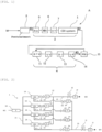
- FIG. 1 is a diagram illustrating an ultrapure water production apparatus A that can implement an electrodeionization system 1 according to an embodiment of the present invention.
- the ultrapure water production apparatus A may be composed of three-stage devices of a pretreatment device 2, a primary pure water production device 3, and a secondary pure water production device (subsystem) 4.
- the primary pure water production device 3 includes the electrodeionization system 1 (denoted as CDI system in FIG. 1 ).
- the pretreatment may be performed, such as by filtration of raw water W, coagulation sedimentation, and microfiltration, to primarily remove suspended solids.
- the primary pure water production device 3 may have a reverse osmosis membrane device 5 that processes pretreated water (also referred to as supply water) W1, a degassing membrane device 6, an ultraviolet oxidation device 7, and the electrodeionization system 1.
- the primary pure water production device 3 may remove most of the electrolytes, fine particles, viable bacteria, etc. in the pretreated water W1 and decompose organic substances.
- the subsystem 4 may be composed of a sub-tank 11 that serves as a water storage tank arranged downstream the above electrodeionization system 1 and stores primary pure water (desalted water) W2 produced in the primary pure water production device 3, an ultraviolet oxidation device 12 that processes the primary pure water W2 supplied from the sub-tank 11 via a pump (not illustrated), a non-regenerative mixed bed type ion exchange device 13, and an ultrafiltration (UF) membrane 14 as a membrane filtration device.
- UF ultrafiltration
- an RO membrane separator or the like may be further provided as required.
- a small amount of organic substances (TOC components) contained in the primary pure water W2 may be oxidized and decomposed by the ultraviolet oxidation device 12 and subsequently processed in the non-regenerative mixed bed type ion exchange device 13, in which residual carbonated ions, organic acids, anionic substances, metal ions, and cationic substances are removed by ion exchange. Then, the ultrafiltration (UF) membrane 14 may remove fine particles to obtain ultrapure water W3, and this may be supplied to a point of use 15. Unused ultrapure water may be flowed back to the sub-tank 11.
- TOC components organic substances contained in the primary pure water W2
- the non-regenerative mixed bed type ion exchange device 13 in which residual carbonated ions, organic acids, anionic substances, metal ions, and cationic substances are removed by ion exchange.
- the ultrafiltration (UF) membrane 14 may remove fine particles to obtain ultrapure water W3, and this may be supplied to a point of use 15. Unused ultrapure water may be flowed back to the sub
- the electrodeionization system 1 according to an embodiment of the present invention will be described with reference to FIG. 2 .
- the electrodeionization system 1 according to an embodiment of the present invention includes a plurality of electrodeionization devices 1A installed in parallel.
- the supply water W1 having an arbitrary flow rate is supplied to each electrodeionization device 1A through a flow path 21 by a pump 1B for water supply capable of varying the flow rate of supply water to the electrodeionization devices 1A.
- the supply water W1 supplied to each electrodeionization device 1A is processed in it into the desalted water (primary pure water) W2 and concentrated water W4.
- the desalted water W2 produced in each electrodeionization device 1A passes through a sub-flow path 22 and joins in a main flow path 23.
- the sub-flow path 22 is provided with a manual valve 1C and a flowmeter 1D
- the main flow path 23 is provided with a first control valve 1E and a flowmeter 1F.
- the concentrated water W4 discharged from each electrodeionization device 1A passes through a sub-path 24 and then joins in a main path 25.
- Each sub-path 24 is provided with a manual valve 1G and a flowmeter 1H
- the main path 25 is provided with a second control valve 1I and a flowmeter 1J.
- the electrodeionization system 1 includes a control device (not illustrated) that can control the first control valve 1E, which is provided in the main flow path 23, and the second control valve 1I, which is provided in the main path 25, in response to changes in the flow rate of supply water W1 from the pump 1B.
- the supply water flow rate varying means which corresponds to the pump 1B in FIG. 2 , is a means for varying the flow rate of supply water W1 to the plurality of electrodeionization devices 1A.
- the supply water flow rate varying means to be adopted may be one that varies the flow rate of supply water W1 within a range of 30% to 100%, assuming that the flow rate of supply water W1 before variation is 100%.
- the flow rate of supply water W1 before variation refers to a flow rate whose maximum value is the sum of the maximum water flow rates listed in the catalogs of respective electrodeionization devices 1A.
- the pump 1B is illustrated as an example of the supply water flow rate varying means, but the supply water flow rate varying means is not limited to the pump 1B, provided that it can vary the flow rate of supply water W1 to the electrodeionization devices 1A.
- a water feed pump or a high-pressure pump (both not illustrated) for supplying water to the RO (reverse osmosis membrane device) 5 in FIG. 1 can also be used.
- the concentrated water flow rate adjusting means which corresponds to the manual valve 1G in FIG. 2 , is a means for adjusting the flow rate of concentrated water W4 discharged from each electrodeionization device 1A.
- the concentrated water flow rate adjusting means is installed in each sub-path 24 through which the concentrated water W4 discharged from each electrodeionization device 1A flows.
- the flow rate of concentrated water W4 discharged from each electrodeionization device 1A may be adjusted to a predetermined value using the concentrated water flow rate adjusting means, and the flow rates of desalted water W2 and concentrated water W4 may be adjusted using the concentrated water flow rate maintaining means, which will be described later, so that even when the flow rate of supply water W1 is varied, the flow rate of concentrated water W4 can be maintained at a constant value.
- the manual valve 1G is illustrated as an example of the concentrated water flow rate adjusting means, but the concentrated water flow rate adjusting means is not limited, provided that it can adjust the flow rate of concentrated water W4 discharged from each electrodeionization device 1A.
- a constant flow rate valve can also be used.
- the concentrated water flow rate maintaining means which corresponds to the first control valve 1E provided in the main flow path 23 and the second control valve 1I provided in the main path 25 in FIG. 2 , is a means for maintaining the flow rate of concentrated water W4 discharged from each electrodeionization device 1A at a certain level or higher. As illustrated in FIG. 2 , the concentrated water flow rate maintaining means is installed only in the main flow path 23 in which the plurality of sub-flow paths 22 are integrated and the main path 25 in which the plurality of sub-paths 24 are integrated.
- the desalted water W2 produced in each of the plurality of electrodeionization devices 1A flows through each of the plurality of sub-flow paths 22 while the concentrated water W4 discharged from each of the plurality of electrodeionization devices 1A flows through each of the plurality of sub-paths 24.
- the first control valve 1E provided in the main flow path 23 and the second control valve 1I provided in the main path 25 may be controlled, for example, in response to changes in the flow rate of supply water W1 from the pump 1B, and it is thereby possible to control the flow rates of the desalted water W2 and concentrated water W4 from the electrodeionization devices 1A. That is, when the flow rate of supply water W1 decreases, the flow rate of concentrated water W4 can be controlled at a certain level or higher by decreasing the flow rate of desalted water W2.
- the concentrated water flow rate maintaining means and the aforementioned concentrated water flow rate adjusting means By the concentrated water flow rate maintaining means and the aforementioned concentrated water flow rate adjusting means, the flow rate of concentrated water W4 discharged from each of the plurality of electrodeionization devices 1A can be maintained at a constant value for each electrodeionization device 1A, and the occurrence of scale can therefore be suppressed. Moreover, by providing the concentrated water flow rate maintaining means only in the main flow path 23 and the main path 25, the number of concentrated water flow rate maintaining means installed can be reduced as compared to a case in which the concentrated water flow rate maintaining means is provided in each of the plurality of sub-flow paths 22 or the plurality of sub-paths 24, and it is therefore possible to suppress the production cost of the electrodeionization system 1.
- the first control valve 1E and the second control valve 1I are illustrated as an example of the concentrated water flow rate maintaining means, but the concentrated water flow rate maintaining means is not limited, provided that it can maintain the flow rate of concentrated water W4 at a certain level or higher.
- a constant flow rate valve provided in the main path 25 can also be used.
- a control method for the electrodeionization system 1 of the present embodiment will now be described below.
- the control method for the electrodeionization system 1 is that for the electrodeionization system 1 including the plurality of electrodeionization devices 1A installed in parallel, and includes a supply water flow rate varying step, a concentrated water flow rate adjusting step, and a concentrated water flow rate maintaining step. Each step will be described below with reference to FIG. 2 .
- the supply water flow rate varying step in an embodiment of the control method for the electrodeionization system 1 is a step in which the flow rate of supply water to each electrodeionization device 1A is varied to an arbitrary amount by the pump 1B for water supply.
- the concentrated water flow rate adjusting step is a step in which the flow rate of concentrated water W4 discharged from each electrodeionization device 1A is adjusted to a predetermined value for each electrodeionization device 1A using the manual valve 1G provided in each sub-path 24.
- the concentrated water flow rate maintaining step is a step in which the flow rate of concentrated water W4 discharged from each of the plurality of electrodeionization devices 1A is maintained at a certain level or higher using the first control valve 1E and the second control valve 1I.
- the first control valve 1E is provided only in the main flow path 23 in which the plurality of sub-flow paths 22 are integrated while the second control valve 1I is provided only in the main path 25 in which the plurality of sub-paths 24 are integrated.
- the desalted water W2 produced in each of the plurality of electrodeionization devices 1A flows through each of the plurality of sub-flow paths 22 while the concentrated water W4 discharged from each of the plurality of electrodeionization devices 1A flows through each of the plurality of sub-paths 24.
- An example of the concentrated water flow rate maintaining step may include reducing the flow rate of desalted water W2 using the first control valve 1E when the flow rate of supply water W1 decreases, and the flow rate of concentrated water W4 can thereby be controlled at a certain level or higher.
- the control method for the electrodeionization system 1 includes the concentrated water flow rate adjusting step and the concentrated water flow rate maintaining step thereby to allow the flow rate of concentrated water W4 to be maintained at a certain level even when the flow rate of supply water is varied in the supply water flow rate varying step, and the occurrence of scale can be suppressed.
- the concentrated water flow rate maintaining step is carried out using control valves provided only in the main flow path 23 and the main path 25, rather than using control values provided in each sub-flow path 22 and each sub-path 24, and the operating cost of the electrodeionization system 1 can thereby be reduced.
- the supply water flow rate varying step may include varying the flow rate of supply water within a range of 30% to 100%, assuming that the flow rate of supply water W1 before variation is 100%.
- the concentrated water W4 discharged from each electrodeionization device 1A varies approximately in proportion to the change in the flow rate of supply water as described in the verification experiment, which will be described later, and the concentrated water W4 can therefore be kept constant.
- the pump 1B is used to vary the flow rate of supply water, but the present invention is not limited to this, and various pumps such as a high-pressure pump may also be used.
- the time from the start to end of the variation of the supply water flow rate (e.g., until the flow rate of supply water reaches 30% from 100%) may be preferably 1 minute to 30 minutes.
- the amount of concentrated water W4 discharged from each electrodeionization device 1A has a more sufficient proportional relationship with respect to changes in the flow rate of supply water, and the flow rate of concentrated water W4 can be kept more constant.
- a method is used in which the flow rate of concentrated water W4 is maintained at a certain level or higher using the first control valve 1E and the second control valve 1I.
- the first control valve 1E is provided in the main flow path 23 in which the sub-flow paths 22 are integrated while the second control valve 1I is provided in the main path 25 in which the sub-paths 24 are integrated.
- the desalted water W2 flows through the sub-flow paths 22 while the concentrated water W4 flows through the sub-paths 24.
- the present invention is not limited to this, and a method using a constant flow rate valve provided in the main path 25 may also be used.
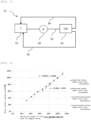
- This testing device 31 includes a supply water tank 32, a supply water flow path 33, a pump 1B, a desalted water (primary pure water) flow path 34, and a concentrated water flow path 35 in addition to the electrodeionization device 1A.
- the desalted water W2 produced in the electrodeionization device 1A and the concentrated water W4 discharged from the electrodeionization device 1A pass through the desalted water flow path 34 and the concentrated water flow path 35, respectively, and flow into the supply water tank 32 again.
- the electrodeionization device 1A used is one employing a counter flow scheme, and the desalted water flow path 34 and the concentrated water flow path 35 are each provided with a flowmeter and a pressure gauge (both not illustrated).
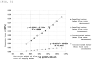
- the pump 1B was used to reduce the flow rate of supply water to the electrodeionization device 1A from 100% to 30% in 20 minutes, assuming that the flow rate of supply water W1 before reduction was 100%, and changes in the flow rate and pressure loss of the primary pure water W2 and concentrated water W4 were measured with respect to the changes in the flow rate of supply water at that time. Then, the flow rate of supply water to the electrodeionization device 1A was returned from 30% to 100% in 20 minutes, and changes in the flow rate and pressure loss of the primary pure water W2 and concentrated water W4 were measured with respect to the changes in the flow rate of supply water at that time. The results of repeating this operation twice are illustrated in FIGS. 4 and 5 . The flowmeter and pressure gauge provided in each of the desalted water flow path 34 and the concentrated water flow path 35 were used for the measurement.
Landscapes
- Chemical & Material Sciences (AREA)
- Engineering & Computer Science (AREA)
- Water Supply & Treatment (AREA)
- Chemical Kinetics & Catalysis (AREA)
- Life Sciences & Earth Sciences (AREA)
- Health & Medical Sciences (AREA)
- Environmental & Geological Engineering (AREA)
- Hydrology & Water Resources (AREA)
- Organic Chemistry (AREA)
- Urology & Nephrology (AREA)
- Analytical Chemistry (AREA)
- Molecular Biology (AREA)
- Electrochemistry (AREA)
- General Chemical & Material Sciences (AREA)
- Water Treatment By Electricity Or Magnetism (AREA)
- Separation Using Semi-Permeable Membranes (AREA)
Abstract
Description
- The present invention relates to an electrodeionization system in which a plurality of electrodeionization devices are provided and relates also to a control method for the electrodeionization system.
- Ultrapure water used in the electronic industry fields such as a semiconductor field is produced by processing raw water with an ultrapure water production apparatus composed of a pretreatment system, a primary pure water system, and a subsystem that processes the primary pure water.
- The primary pure water production device included in such an ultrapure water production apparatus is a highly versatile system that is used in various fields such as those for pharmaceuticals and foods in addition to the field of ultrapure water production apparatuses. The configuration of the primary pure water system is generally a two-stage configuration composed of a reverse osmosis membrane (RO membrane) device and an electrodeionization device. The reverse osmosis membrane (RO membrane) device removes silica and salts and also removes ionic and colloidal TOC.
- Here, the electrodeionization device generally has a configuration in which cation exchange membranes and anion exchange membranes are alternately arranged between a cathode and an anode to alternately form desalting chambers and concentrating chambers and the desalting chambers are filled with ion exchange resin, and performs removal of various inorganic or organic anions and cations.
- When water is supplied to the desalting chambers of the electrodeionization device, ions in the water migrate in the desalting chambers toward the ion exchange resin of either the anode or the cathode due to the electrical charge possessed by the ions. The migrated ions pass through the ion exchange resin and enter the concentrating chambers, so highly desalted pure water is produced in the desalting chambers. On the other hand, ions migrated to the concentrating chambers stay there and are finally discharged as concentrated water.
- The electrodeionization device is often used as one of a plurality of electrodeionization devices that are installed in parallel in an electrodeionization system, such as when the amount of water to be treated is large. In such an electrodeionization system, conditions of water supply to the electrodeionization system are often changed to follow the conditions of other systems that are combined before and after that system. For example, in an electrodeionization system used in the primary pure water system of an ultrapure water production apparatus, the flow rate of supply water to the electrodeionization system is increased or decreased depending on the amount of pure water used in the combined subsystem thereby to control the amount of primary pure water produced.
- Unfortunately, when the flow rate of supply water is decreased during operation of the electrodeionization system, there is a problem in that scale may occur due to excessive concentration of the concentrated water in each of the plurality of electrodeionization devices installed.
- The present invention has been made in view of the above problem, and an object of the present invention is to provide an electrodeionization system that reduces the production cost while suppressing the occurrence of scale due to a decrease in the flow rate of supply water to each electrodeionization device.
- In view of the above object, first, the present invention provides an electrodeionization system comprising a plurality of electrodeionization devices installed in parallel, the electrodeionization system comprising: a supply water flow rate varying means that varies a flow rate of supply water to the plurality of electrodeionization devices; a concentrated water flow rate adjusting means that adjusts, for each electrodeionization device, a flow rate of concentrated water discharged from each of the plurality of electrodeionization devices; and a concentrated water flow rate maintaining means that maintains the flow rate of the concentrated water discharged from each of the plurality of electrodeionization devices at a certain level or higher, wherein the concentrated water flow rate maintaining means is installed only in a main flow path in which a plurality of sub-flow paths are integrated and a main path in which a plurality of sub-paths are integrated, wherein desalted water produced in each of the plurality of electrodeionization devices flows through each of the plurality of sub-flow paths while concentrated water discharged from each of the plurality of electrodeionization devices flows through each of the plurality of sub-paths (Invention 1).
- According to the invention (Invention 1), even when the flow rate of supply water to the plurality of electrodeionization devices (also simply referred to as the flow rate of supply water) is varied, the flow rate of concentrated water discharged from each electrodeionization device (also simply referred to as the flow rate of concentrated water) can be kept constant thereby to suppress the occurrence of scale. Moreover, even when the concentrated water flow rate maintaining means is not provided in each of the sub-flow paths or sub-paths, the flow rate of concentrated water can be kept constant, provided that the concentrated water flow rate maintaining means is provided only in each of the main flow path for desalted water and the main path for concentrated water, and it is therefore possible to reduce the production cost of the electrodeionization system.
- In the above invention (Invention 1), the supply water flow rate varying means may increase or decrease the flow rate of supply water within a range of 30% to 100% (Invention 2) .
- In the above invention (
Invention 1 or 2), the concentrated water flow rate maintaining means may include a first control valve provided in the main flow path and a second control valve provided in the main path (Invention 3) . - In the above invention (
Invention 1 to 3), the concentrated water flow rate adjusting means may be a manual valve provided in each of the sub-paths (Invention 4). - Second, the present invention provides a control method for an electrodeionization system comprising a plurality of electrodeionization devices installed in parallel, the control method comprising: a supply water flow rate varying step of varying a flow rate of supply water to the plurality of electrodeionization devices; a concentrated water flow rate adjusting step of adjusting, for each electrodeionization device, a flow rate of concentrated water discharged from each of the plurality of electrodeionization devices; and a concentrated water flow rate maintaining step of maintaining the flow rate of the concentrated water discharged from each of the plurality of electrodeionization devices at a certain level or higher using a first control valve and a second control valve, wherein the first control valve is provided only in a main flow path in which a plurality of sub-flow paths are integrated while the second control valve is provided only in a main path in which a plurality of sub-paths are integrated, wherein desalted water produced in each of the plurality of electrodeionization devices flows through each of the plurality of sub-flow paths while concentrated water discharged from each of the plurality of electrodeionization devices flows through each of the plurality of sub-paths (Invention 5).
- According to the invention (Invention 5), even when the flow rate of supply water to each electrodeionization device is varied in the electrodeionization system including the plurality of electrodeionization devices, the flow rate of concentrated water discharged from each electrodeionization device can be kept constant thereby to suppress the occurrence of scale. Moreover, even when each sub-flow path or each sub-path does not include a control valve, the flow rate of concentrated water can be kept constant using the control valves provided only in the main flow path for flowing the desalted water and the main path for flowing the concentrated water, and it is therefore possible to reduce the operation cost of the electrodeionization system.
- In the above invention (Invention 5), the supply water flow rate varying step may include increasing or decreasing the flow rate of supply water within a range of 30% to 100% (Invention 6).
- According to the present invention, it is possible to provide an electrodeionization system that reduces the production cost while suppressing the occurrence of scale due to a decrease in the flow rate of supply water to each electrodeionization device.
-
-
FIG. 1 is a flow diagram illustrating an ultrapure water production apparatus to which an electrodeionization system according to the present invention can be applied. -
FIG. 2 is a schematic diagram illustrating the electrodeionization system according to the present invention. -
FIG. 3 is a schematic diagram illustrating the control structure of a testing device used in the verification experiment. -
FIG. 4 is a graph illustrating changes in the flow rates (amounts of water) of desalted water and concentrated water with respect to changes in the flow rate of supply water in the verification experiment. -
FIG. 5 is a graph illustrating changes in the pressure losses of desalted water and concentrated water with respect to changes in the flow rate of supply water in the verification experiment. - Hereinafter, the electrodeionization system of the present invention will be described with reference to the accompanying drawings. For descriptive purposes, the description will be made partially using a diagram in which the electrodeionization system is provided in an ultrapure water production apparatus, but the electrodeionization system and the control method for the electrodeionization device in the present invention can be used not only in the ultrapure water production apparatus but also in various fields such as those for pharmaceuticals and foods.
-
FIG. 1 is a diagram illustrating an ultrapure water production apparatus A that can implement anelectrodeionization system 1 according to an embodiment of the present invention. As illustrated inFIG. 1 , the ultrapure water production apparatus A may be composed of three-stage devices of apretreatment device 2, a primary purewater production device 3, and a secondary pure water production device (subsystem) 4. The primary purewater production device 3 includes the electrodeionization system 1 (denoted as CDI system inFIG. 1 ). In thepretreatment device 2 of such an ultrapure water production apparatus A, the pretreatment may be performed, such as by filtration of raw water W, coagulation sedimentation, and microfiltration, to primarily remove suspended solids. - The primary pure
water production device 3 may have a reverseosmosis membrane device 5 that processes pretreated water (also referred to as supply water) W1, adegassing membrane device 6, anultraviolet oxidation device 7, and theelectrodeionization system 1. The primary purewater production device 3 may remove most of the electrolytes, fine particles, viable bacteria, etc. in the pretreated water W1 and decompose organic substances. - The
subsystem 4 may be composed of asub-tank 11 that serves as a water storage tank arranged downstream theabove electrodeionization system 1 and stores primary pure water (desalted water) W2 produced in the primary purewater production device 3, anultraviolet oxidation device 12 that processes the primary pure water W2 supplied from thesub-tank 11 via a pump (not illustrated), a non-regenerative mixed bed typeion exchange device 13, and an ultrafiltration (UF)membrane 14 as a membrane filtration device. In some cases, an RO membrane separator or the like may be further provided as required. In thissubsystem 4, a small amount of organic substances (TOC components) contained in the primary pure water W2 may be oxidized and decomposed by theultraviolet oxidation device 12 and subsequently processed in the non-regenerative mixed bed typeion exchange device 13, in which residual carbonated ions, organic acids, anionic substances, metal ions, and cationic substances are removed by ion exchange. Then, the ultrafiltration (UF)membrane 14 may remove fine particles to obtain ultrapure water W3, and this may be supplied to a point ofuse 15. Unused ultrapure water may be flowed back to thesub-tank 11. - The
electrodeionization system 1 according to an embodiment of the present invention will be described with reference toFIG. 2 . As illustrated inFIG. 2 , theelectrodeionization system 1 according to an embodiment of the present invention includes a plurality ofelectrodeionization devices 1A installed in parallel. - In the
electrodeionization system 1, first, the supply water W1 having an arbitrary flow rate is supplied to eachelectrodeionization device 1A through aflow path 21 by apump 1B for water supply capable of varying the flow rate of supply water to theelectrodeionization devices 1A. The supply water W1 supplied to eachelectrodeionization device 1A is processed in it into the desalted water (primary pure water) W2 and concentrated water W4. - The desalted water W2 produced in each
electrodeionization device 1A passes through asub-flow path 22 and joins in amain flow path 23. Thesub-flow path 22 is provided with amanual valve 1C and aflowmeter 1D, and themain flow path 23 is provided with afirst control valve 1E and aflowmeter 1F. On the other hand, the concentrated water W4 discharged from eachelectrodeionization device 1A passes through asub-path 24 and then joins in amain path 25. Eachsub-path 24 is provided with amanual valve 1G and aflowmeter 1H, and themain path 25 is provided with a second control valve 1I and aflowmeter 1J. - In addition, the
electrodeionization system 1 includes a control device (not illustrated) that can control thefirst control valve 1E, which is provided in themain flow path 23, and the second control valve 1I, which is provided in themain path 25, in response to changes in the flow rate of supply water W1 from thepump 1B. - The supply water flow rate varying means, which corresponds to the
pump 1B inFIG. 2 , is a means for varying the flow rate of supply water W1 to the plurality ofelectrodeionization devices 1A. The supply water flow rate varying means to be adopted may be one that varies the flow rate of supply water W1 within a range of 30% to 100%, assuming that the flow rate of supply water W1 before variation is 100%. Here, the flow rate of supply water W1 before variation refers to a flow rate whose maximum value is the sum of the maximum water flow rates listed in the catalogs ofrespective electrodeionization devices 1A. When the variation in the flow rate of supply water W1 falls within the above range, as will be described later in the verification experiment, the flow rate of desalted water W2 produced in eachelectrodeionization device 1A and the flow rate of concentrated water W4 discharged from eachelectrodeionization device 1A vary approximately in proportion to the variation in the flow rate of supply water W1, and therefore the flow rate of concentrated water W4 can more readily kept constant. - In
FIG. 2 , thepump 1B is illustrated as an example of the supply water flow rate varying means, but the supply water flow rate varying means is not limited to thepump 1B, provided that it can vary the flow rate of supply water W1 to theelectrodeionization devices 1A. For example, a water feed pump or a high-pressure pump (both not illustrated) for supplying water to the RO (reverse osmosis membrane device) 5 inFIG. 1 can also be used. - The concentrated water flow rate adjusting means, which corresponds to the
manual valve 1G inFIG. 2 , is a means for adjusting the flow rate of concentrated water W4 discharged from eachelectrodeionization device 1A. The concentrated water flow rate adjusting means is installed in each sub-path 24 through which the concentrated water W4 discharged from eachelectrodeionization device 1A flows. At the time of starting up theelectrodeionization system 1 or at the initial stage of operation, the flow rate of concentrated water W4 discharged from eachelectrodeionization device 1A may be adjusted to a predetermined value using the concentrated water flow rate adjusting means, and the flow rates of desalted water W2 and concentrated water W4 may be adjusted using the concentrated water flow rate maintaining means, which will be described later, so that even when the flow rate of supply water W1 is varied, the flow rate of concentrated water W4 can be maintained at a constant value. - In
FIG. 2 , themanual valve 1G is illustrated as an example of the concentrated water flow rate adjusting means, but the concentrated water flow rate adjusting means is not limited, provided that it can adjust the flow rate of concentrated water W4 discharged from eachelectrodeionization device 1A. For example, a constant flow rate valve can also be used. - The concentrated water flow rate maintaining means, which corresponds to the
first control valve 1E provided in themain flow path 23 and the second control valve 1I provided in themain path 25 inFIG. 2 , is a means for maintaining the flow rate of concentrated water W4 discharged from eachelectrodeionization device 1A at a certain level or higher. As illustrated inFIG. 2 , the concentrated water flow rate maintaining means is installed only in themain flow path 23 in which the plurality ofsub-flow paths 22 are integrated and themain path 25 in which the plurality ofsub-paths 24 are integrated. The desalted water W2 produced in each of the plurality ofelectrodeionization devices 1A flows through each of the plurality ofsub-flow paths 22 while the concentrated water W4 discharged from each of the plurality ofelectrodeionization devices 1A flows through each of the plurality ofsub-paths 24. - In the concentrated water flow rate maintaining means, the
first control valve 1E provided in themain flow path 23 and the second control valve 1I provided in themain path 25 may be controlled, for example, in response to changes in the flow rate of supply water W1 from thepump 1B, and it is thereby possible to control the flow rates of the desalted water W2 and concentrated water W4 from theelectrodeionization devices 1A. That is, when the flow rate of supply water W1 decreases, the flow rate of concentrated water W4 can be controlled at a certain level or higher by decreasing the flow rate of desalted water W2. - By the concentrated water flow rate maintaining means and the aforementioned concentrated water flow rate adjusting means, the flow rate of concentrated water W4 discharged from each of the plurality of
electrodeionization devices 1A can be maintained at a constant value for eachelectrodeionization device 1A, and the occurrence of scale can therefore be suppressed. Moreover, by providing the concentrated water flow rate maintaining means only in themain flow path 23 and themain path 25, the number of concentrated water flow rate maintaining means installed can be reduced as compared to a case in which the concentrated water flow rate maintaining means is provided in each of the plurality ofsub-flow paths 22 or the plurality ofsub-paths 24, and it is therefore possible to suppress the production cost of theelectrodeionization system 1. - In
FIG. 2 , thefirst control valve 1E and the second control valve 1I are illustrated as an example of the concentrated water flow rate maintaining means, but the concentrated water flow rate maintaining means is not limited, provided that it can maintain the flow rate of concentrated water W4 at a certain level or higher. For example, a constant flow rate valve provided in themain path 25 can also be used. - A control method for the
electrodeionization system 1 of the present embodiment will now be described below. - The control method for the
electrodeionization system 1 according to an embodiment of the present invention is that for theelectrodeionization system 1 including the plurality ofelectrodeionization devices 1A installed in parallel, and includes a supply water flow rate varying step, a concentrated water flow rate adjusting step, and a concentrated water flow rate maintaining step. Each step will be described below with reference toFIG. 2 . - The supply water flow rate varying step in an embodiment of the control method for the
electrodeionization system 1 is a step in which the flow rate of supply water to eachelectrodeionization device 1A is varied to an arbitrary amount by thepump 1B for water supply. The concentrated water flow rate adjusting step is a step in which the flow rate of concentrated water W4 discharged from eachelectrodeionization device 1A is adjusted to a predetermined value for eachelectrodeionization device 1A using themanual valve 1G provided in each sub-path 24. - The concentrated water flow rate maintaining step is a step in which the flow rate of concentrated water W4 discharged from each of the plurality of
electrodeionization devices 1A is maintained at a certain level or higher using thefirst control valve 1E and the second control valve 1I. Thefirst control valve 1E is provided only in themain flow path 23 in which the plurality ofsub-flow paths 22 are integrated while the second control valve 1I is provided only in themain path 25 in which the plurality ofsub-paths 24 are integrated. The desalted water W2 produced in each of the plurality ofelectrodeionization devices 1A flows through each of the plurality ofsub-flow paths 22 while the concentrated water W4 discharged from each of the plurality ofelectrodeionization devices 1A flows through each of the plurality ofsub-paths 24. An example of the concentrated water flow rate maintaining step may include reducing the flow rate of desalted water W2 using thefirst control valve 1E when the flow rate of supply water W1 decreases, and the flow rate of concentrated water W4 can thereby be controlled at a certain level or higher. - The control method for the
electrodeionization system 1 includes the concentrated water flow rate adjusting step and the concentrated water flow rate maintaining step thereby to allow the flow rate of concentrated water W4 to be maintained at a certain level even when the flow rate of supply water is varied in the supply water flow rate varying step, and the occurrence of scale can be suppressed. Moreover, the concentrated water flow rate maintaining step is carried out using control valves provided only in themain flow path 23 and themain path 25, rather than using control values provided in eachsub-flow path 22 and each sub-path 24, and the operating cost of theelectrodeionization system 1 can thereby be reduced. - The supply water flow rate varying step may include varying the flow rate of supply water within a range of 30% to 100%, assuming that the flow rate of supply water W1 before variation is 100%. When the flow rate of supply water falls within the above range, the concentrated water W4 discharged from each
electrodeionization device 1A varies approximately in proportion to the change in the flow rate of supply water as described in the verification experiment, which will be described later, and the concentrated water W4 can therefore be kept constant. In the above-described supply water flow rate varying step, thepump 1B is used to vary the flow rate of supply water, but the present invention is not limited to this, and various pumps such as a high-pressure pump may also be used. - In the supply water flow rate varying step, the time from the start to end of the variation of the supply water flow rate (e.g., until the flow rate of supply water reaches 30% from 100%) may be preferably 1 minute to 30 minutes. When the varying time falls within the above range, the amount of concentrated water W4 discharged from each
electrodeionization device 1A has a more sufficient proportional relationship with respect to changes in the flow rate of supply water, and the flow rate of concentrated water W4 can be kept more constant. - In the above-described supply water flow rate varying step, a method is described in which the
manual valves 1G provided in the sub-paths 24 are used so that the flow rate of concentrated water W4 discharged from eachelectrodeionization device 1A becomes a predetermined value for eachelectrodeionization device 1A, but the present invention is not limited to this, and a method using a constant flow rate valve may also be used. - In the above-described concentrated water flow rate maintaining step, a method is used in which the flow rate of concentrated water W4 is maintained at a certain level or higher using the
first control valve 1E and the second control valve 1I. Thefirst control valve 1E is provided in themain flow path 23 in which thesub-flow paths 22 are integrated while the second control valve 1I is provided in themain path 25 in which the sub-paths 24 are integrated. The desalted water W2 flows through thesub-flow paths 22 while the concentrated water W4 flows through the sub-paths 24. However, the present invention is not limited to this, and a method using a constant flow rate valve provided in themain path 25 may also be used. - A verification experiment was conducted to confirm the effects of the present invention using a
testing device 31 for controlling anelectrodeionization device 1A illustrated inFIG. 3 . Thistesting device 31 includes asupply water tank 32, a supplywater flow path 33, apump 1B, a desalted water (primary pure water) flowpath 34, and a concentratedwater flow path 35 in addition to theelectrodeionization device 1A. The desalted water W2 produced in theelectrodeionization device 1A and the concentrated water W4 discharged from theelectrodeionization device 1A pass through the desaltedwater flow path 34 and the concentratedwater flow path 35, respectively, and flow into thesupply water tank 32 again. Theelectrodeionization device 1A used is one employing a counter flow scheme, and the desaltedwater flow path 34 and the concentratedwater flow path 35 are each provided with a flowmeter and a pressure gauge (both not illustrated). - In the
testing device 31, thepump 1B was used to reduce the flow rate of supply water to theelectrodeionization device 1A from 100% to 30% in 20 minutes, assuming that the flow rate of supply water W1 before reduction was 100%, and changes in the flow rate and pressure loss of the primary pure water W2 and concentrated water W4 were measured with respect to the changes in the flow rate of supply water at that time. Then, the flow rate of supply water to theelectrodeionization device 1A was returned from 30% to 100% in 20 minutes, and changes in the flow rate and pressure loss of the primary pure water W2 and concentrated water W4 were measured with respect to the changes in the flow rate of supply water at that time. The results of repeating this operation twice are illustrated inFIGS. 4 and5 . The flowmeter and pressure gauge provided in each of the desaltedwater flow path 34 and the concentratedwater flow path 35 were used for the measurement. - As illustrated in
FIGS. 4 and5 , it has been confirmed that even when the flow rate of supply water W1 is varied between 100% and 30%, the flow rate and pressure of the primary pure water W2 and concentrated water W4 have an approximately proportional relationship with respect to the changes in the flow rate of supply water W1. From these results, it is considered that even in theelectrodeionization system 1 including a plurality ofelectrodeionization devices 1A as in the present invention, the flow rate of concentrated water W4 discharged from eachelectrodeionization device 1A can be controlled at a constant value only by thefirst control valve 1E provided in themain flow path 23 and the second control valve 1I provided in themain path 25, provided that the amount of concentrated water W4 discharged can be adjusted to a predetermined value for eachelectrodeionization device 1A. - The aforementioned embodiments are described to facilitate understanding of the present invention and are not described to limit the present invention. It is therefore intended that the elements disclosed in the above embodiments include all design changes and equivalents to fall within the technical scope of the present invention.
-
- A
- Ultrapure water production apparatus
- 1
- Electrodeionization system
- 1A
- Electrodeionization device
- 1B
- Pump
- 1C, 1G
- Manual valve
- 1D, 1F, 1H, 1J
- Flowmeter
- 1E
- First control valve
- 1I
- Second control valve
- 2
- Pretreatment device
- 3
- Primary pure water production device
- 4
- Secondary pure water production device (subsystem)
- 5
- Reverse osmosis membrane device
- 6
- Degassing membrane device
- 7
- Ultraviolet oxidation device
- 11
- Sub-tank
- 12
- Ultraviolet oxidation device
- 13
- Non-regenerative mixed bed type ion exchange device
- 14
- Ultrafiltration (UF) membrane
- 15
- Point of use
- 21
- Flow path for supply water
- 22
- Sub-flow path for desalted water
- 23
- Main flow path for desalted water
- 24
- Sub-path for concentrated water
- 25
- Main path for concentrated water
- 31
- Testing device
- 32
- Supply water tank
- 33
- Supply water flow path
- 34
- Desalted water (primary pure water) flow path
- 35
- Concentrated water flow path
- W
- Raw water
- W1
- Pretreated water (supply water)
- W2
- Primary pure water (desalted water)
- W3
- Ultrapure water (secondary pure water)
- W4
- Concentrated water
Claims (6)
- An electrodeionization system comprising a plurality of electrodeionization devices installed in parallel, the electrodeionization system comprising:a supply water flow rate varying means that varies a flow rate of supply water to the plurality of electrodeionization devices;a concentrated water flow rate adjusting means that adjusts, for each electrodeionization device, a flow rate of concentrated water discharged from each of the plurality of electrodeionization devices; anda concentrated water flow rate maintaining means that maintains the flow rate of the concentrated water discharged from each of the plurality of electrodeionization devices at a certain level or higher,wherein the concentrated water flow rate maintaining means is installed only in a main flow path in which a plurality of sub-flow paths are integrated and a main path in which a plurality of sub-paths are integrated, wherein desalted water produced in each of the plurality of electrodeionization devices flows through each of the plurality of sub-flow paths while concentrated water discharged from each of the plurality of electrodeionization devices flows through each of the plurality of sub-paths.
- The electrodeionization system according to claim 1, wherein the supply water flow rate varying means increases or decreases the flow rate of supply water within a range of 30% to 100%.
- The electrodeionization system according to claim 1 or 2, wherein the concentrated water flow rate maintaining means includes a first control valve provided in the main flow path and a second control valve provided in the main path.
- The electrodeionization system according to any one of claims 1 to 3, wherein the concentrated water flow rate adjusting means is a manual valve provided in each of the sub-paths.
- A control method for an electrodeionization system comprising a plurality of electrodeionization devices installed in parallel, the control method comprising:a supply water flow rate varying step of varying a flow rate of supply water to the plurality of electrodeionization devices;a concentrated water flow rate adjusting step of adjusting, for each electrodeionization device, a flow rate of concentrated water discharged from each of the plurality of electrodeionization devices; anda concentrated water flow rate maintaining step of maintaining the flow rate of the concentrated water discharged from each of the plurality of electrodeionization devices at a certain level or higher using a first control valve and a second control valve, wherein the first control valve is provided only in a main flow path in which a plurality of sub-flow paths are integrated while the second control valve is provided only in a main path in which a plurality of sub-paths are integrated, wherein desalted water produced in each of the plurality of electrodeionization devices flows through each of the plurality of sub-flow paths while concentrated water discharged from each of the plurality of electrodeionization devices flows through each of the plurality of sub-paths.
- The control method for an electrodeionization system according to claim 5, wherein the supply water flow rate varying step includes increasing or decreasing the flow rate of supply water within a range of 30% to 100%.
Applications Claiming Priority (2)
| Application Number | Priority Date | Filing Date | Title |
|---|---|---|---|
| JP2021065340A JP7103467B1 (en) | 2021-04-07 | 2021-04-07 | Control method of electric deionization system and electric deionization system |
| PCT/JP2022/012163 WO2022215475A1 (en) | 2021-04-07 | 2022-03-17 | Electrodeionization system and control method for electrodeionization system |
Publications (2)
| Publication Number | Publication Date |
|---|---|
| EP4321488A1 true EP4321488A1 (en) | 2024-02-14 |
| EP4321488A4 EP4321488A4 (en) | 2024-11-06 |
Family
ID=82482473
Family Applications (1)
| Application Number | Title | Priority Date | Filing Date |
|---|---|---|---|
| EP22784460.2A Pending EP4321488A4 (en) | 2021-04-07 | 2022-03-17 | ELECTRODEIONIZATION SYSTEM AND CONTROL METHOD FOR ELECTRODEIONIZATION SYSTEM |
Country Status (7)
| Country | Link |
|---|---|
| US (1) | US20240182330A1 (en) |
| EP (1) | EP4321488A4 (en) |
| JP (1) | JP7103467B1 (en) |
| KR (1) | KR20230167342A (en) |
| CN (1) | CN117157254A (en) |
| TW (1) | TW202239463A (en) |
| WO (1) | WO2022215475A1 (en) |
Families Citing this family (3)
| Publication number | Priority date | Publication date | Assignee | Title |
|---|---|---|---|---|
| JP7816616B2 (en) * | 2024-07-25 | 2026-02-18 | 栗田工業株式会社 | Electrodeionization apparatus and its operating method |
| WO2026023244A1 (en) * | 2024-07-25 | 2026-01-29 | 栗田工業株式会社 | Electric deionization apparatus and method for operating same |
| JP2026068856A (en) * | 2024-10-11 | 2026-04-23 | 栗田工業株式会社 | Control method for an electrodeionizer |
Family Cites Families (13)
| Publication number | Priority date | Publication date | Assignee | Title |
|---|---|---|---|---|
| JPH07106350B2 (en) * | 1986-07-31 | 1995-11-15 | バブコツク日立株式会社 | Operating method of electrodialysis desalination equipment |
| JP3385553B2 (en) * | 1999-03-25 | 2003-03-10 | オルガノ株式会社 | Electric deionized water production apparatus and deionized water production method |
| JP2001314863A (en) * | 2000-05-08 | 2001-11-13 | Kurita Water Ind Ltd | Pure water production apparatus and pure water production method |
| US6905608B2 (en) | 2002-01-22 | 2005-06-14 | Exergy Technologies Corporation | Advanced electrodeionization for fluid recycling |
| JP4978593B2 (en) * | 2008-09-01 | 2012-07-18 | 三浦工業株式会社 | Pure water production system |
| CN201694874U (en) * | 2009-10-22 | 2011-01-05 | 烟台大学 | An EDI membrane stack for heavy metal wastewater treatment |
| JP6028539B2 (en) | 2012-11-26 | 2016-11-16 | 三浦工業株式会社 | Pure water production equipment |
| JP2014108382A (en) * | 2012-11-30 | 2014-06-12 | Miura Co Ltd | Pure water production apparatus |
| JP6167939B2 (en) * | 2014-03-04 | 2017-07-26 | 三浦工業株式会社 | Water treatment equipment |
| JP2018034103A (en) * | 2016-08-30 | 2018-03-08 | 栗田工業株式会社 | Pure water production equipment |
| CN106380032A (en) | 2016-11-01 | 2017-02-08 | 深圳恒通源环保科技有限公司 | Water treatment equipment |
| CN106927608A (en) | 2017-04-28 | 2017-07-07 | 南京源自电力自动化设备有限公司 | Nuclear power EDI is electrolysed demineralizer |
| CN112079495B (en) | 2020-08-31 | 2023-01-06 | 华北电力科学研究院有限责任公司 | Automatic control system and method for combination of reverse osmosis equipment and EDI device |
-
2021
- 2021-04-07 JP JP2021065340A patent/JP7103467B1/en active Active
-
2022
- 2022-03-17 EP EP22784460.2A patent/EP4321488A4/en active Pending
- 2022-03-17 US US18/554,019 patent/US20240182330A1/en active Pending
- 2022-03-17 WO PCT/JP2022/012163 patent/WO2022215475A1/en not_active Ceased
- 2022-03-17 CN CN202280026800.3A patent/CN117157254A/en active Pending
- 2022-03-17 KR KR1020237028910A patent/KR20230167342A/en active Pending
- 2022-04-01 TW TW111112809A patent/TW202239463A/en unknown
Also Published As
| Publication number | Publication date |
|---|---|
| WO2022215475A1 (en) | 2022-10-13 |
| JP2022160867A (en) | 2022-10-20 |
| JP7103467B1 (en) | 2022-07-20 |
| US20240182330A1 (en) | 2024-06-06 |
| TW202239463A (en) | 2022-10-16 |
| EP4321488A4 (en) | 2024-11-06 |
| KR20230167342A (en) | 2023-12-08 |
| CN117157254A (en) | 2023-12-01 |
Similar Documents
| Publication | Publication Date | Title |
|---|---|---|
| EP4321488A1 (en) | Electrodeionization system and control method for electrodeionization system | |
| US12570546B2 (en) | Control method for ultrapure water producing apparatus | |
| US20240157300A1 (en) | Method for controlling electrodeionization device | |
| JP7677474B2 (en) | Method for controlling a pure water production system | |
| JP7831532B1 (en) | Control method for a pure water production system | |
| JP7559855B2 (en) | Method for controlling a pure water production system | |
| JP7487812B1 (en) | Method for controlling reverse osmosis membrane device in pure water production system | |
| JP7823701B1 (en) | Control method for ultrapure water production equipment | |
| WO2026079320A1 (en) | Method for controlling electrodeionization device | |
| WO2025211052A1 (en) | Pure water production device control method | |
| JP2025182884A (en) | Control method for pure water production system and pure water production system | |
| WO2025225161A1 (en) | Method of operating reverse osmosis membrane device | |
| TW202613040A (en) | Control methods for pure water production systems and pure water production systems | |
| TW202446482A (en) | Ion exchange system and ultrapure water production equipment |
Legal Events
| Date | Code | Title | Description |
|---|---|---|---|
| STAA | Information on the status of an ep patent application or granted ep patent |
Free format text: STATUS: THE INTERNATIONAL PUBLICATION HAS BEEN MADE |
|
| PUAI | Public reference made under article 153(3) epc to a published international application that has entered the european phase |
Free format text: ORIGINAL CODE: 0009012 |
|
| STAA | Information on the status of an ep patent application or granted ep patent |
Free format text: STATUS: REQUEST FOR EXAMINATION WAS MADE |
|
| 17P | Request for examination filed |
Effective date: 20231010 |
|
| AK | Designated contracting states |
Kind code of ref document: A1 Designated state(s): AL AT BE BG CH CY CZ DE DK EE ES FI FR GB GR HR HU IE IS IT LI LT LU LV MC MK MT NL NO PL PT RO RS SE SI SK SM TR |
|
| DAV | Request for validation of the european patent (deleted) | ||
| DAX | Request for extension of the european patent (deleted) | ||
| REG | Reference to a national code |
Ref country code: DE Ref legal event code: R079 Free format text: PREVIOUS MAIN CLASS: C02F0001469000 Ipc: B01D0061540000 |
|
| A4 | Supplementary search report drawn up and despatched |
Effective date: 20241009 |
|
| RIC1 | Information provided on ipc code assigned before grant |
Ipc: C02F 103/04 20060101ALN20241002BHEP Ipc: C02F 1/52 20230101ALN20241002BHEP Ipc: C02F 1/44 20230101ALN20241002BHEP Ipc: C02F 1/42 20230101ALN20241002BHEP Ipc: C02F 1/32 20230101ALN20241002BHEP Ipc: C02F 1/20 20230101ALN20241002BHEP Ipc: C02F 9/00 20230101ALI20241002BHEP Ipc: C02F 1/469 20230101ALI20241002BHEP Ipc: B01D 61/54 20060101AFI20241002BHEP |