EP4321285A1 - Cutting tool - Google Patents
Cutting tool Download PDFInfo
- Publication number
- EP4321285A1 EP4321285A1 EP21935922.1A EP21935922A EP4321285A1 EP 4321285 A1 EP4321285 A1 EP 4321285A1 EP 21935922 A EP21935922 A EP 21935922A EP 4321285 A1 EP4321285 A1 EP 4321285A1
- Authority
- EP
- European Patent Office
- Prior art keywords
- groove
- main body
- installation
- rotation axis
- cutting
- Prior art date
- Legal status (The legal status is an assumption and is not a legal conclusion. Google has not performed a legal analysis and makes no representation as to the accuracy of the status listed.)
- Pending
Links
- 238000009434 installation Methods 0.000 claims abstract description 171
- 238000000034 method Methods 0.000 description 10
- 230000000052 comparative effect Effects 0.000 description 5
- 230000000694 effects Effects 0.000 description 4
- 239000000463 material Substances 0.000 description 4
- 238000010998 test method Methods 0.000 description 4
- 238000010586 diagram Methods 0.000 description 2
- 229910000975 Carbon steel Inorganic materials 0.000 description 1
- 239000010962 carbon steel Substances 0.000 description 1
- 239000002826 coolant Substances 0.000 description 1
- 230000007423 decrease Effects 0.000 description 1
- 230000005484 gravity Effects 0.000 description 1
- 238000012986 modification Methods 0.000 description 1
- 230000004048 modification Effects 0.000 description 1
- 230000002093 peripheral effect Effects 0.000 description 1
- 230000002265 prevention Effects 0.000 description 1
- 102220005308 rs33960931 Human genes 0.000 description 1
Images




Classifications
-
- B—PERFORMING OPERATIONS; TRANSPORTING
- B23—MACHINE TOOLS; METAL-WORKING NOT OTHERWISE PROVIDED FOR
- B23C—MILLING
- B23C5/00—Milling-cutters
- B23C5/006—Details of the milling cutter body
-
- B—PERFORMING OPERATIONS; TRANSPORTING
- B23—MACHINE TOOLS; METAL-WORKING NOT OTHERWISE PROVIDED FOR
- B23C—MILLING
- B23C5/00—Milling-cutters
- B23C5/02—Milling-cutters characterised by the shape of the cutter
- B23C5/10—Shank-type cutters, i.e. with an integral shaft
- B23C5/109—Shank-type cutters, i.e. with an integral shaft with removable cutting inserts
-
- B—PERFORMING OPERATIONS; TRANSPORTING
- B23—MACHINE TOOLS; METAL-WORKING NOT OTHERWISE PROVIDED FOR
- B23C—MILLING
- B23C2200/00—Details of milling cutting inserts
- B23C2200/36—Other features of the milling insert not covered by B23C2200/04 - B23C2200/32
- B23C2200/367—Mounted tangentially, i.e. where the rake face is not the face with largest area
-
- B—PERFORMING OPERATIONS; TRANSPORTING
- B23—MACHINE TOOLS; METAL-WORKING NOT OTHERWISE PROVIDED FOR
- B23C—MILLING
- B23C2210/00—Details of milling cutters
- B23C2210/16—Fixation of inserts or cutting bits in the tool
- B23C2210/168—Seats for cutting inserts, supports for replacable cutting bits
-
- B—PERFORMING OPERATIONS; TRANSPORTING
- B23—MACHINE TOOLS; METAL-WORKING NOT OTHERWISE PROVIDED FOR
- B23C—MILLING
- B23C2210/00—Details of milling cutters
- B23C2210/28—Arrangement of teeth
- B23C2210/282—Unequal angles between the cutting edges, i.e. cutting edges unequally spaced in the circumferential direction
-
- B—PERFORMING OPERATIONS; TRANSPORTING
- B23—MACHINE TOOLS; METAL-WORKING NOT OTHERWISE PROVIDED FOR
- B23C—MILLING
- B23C2250/00—Compensating adverse effects during milling
- B23C2250/16—Damping vibrations
Definitions
- the present disclosure relates to a cutting tool.
- a cutting tool including a rotatable main body and a plurality of cutting inserts disposed on wall surfaces of chip discharge grooves formed on an outer periphery of the main body (for example, see Japanese Patent Laying-Open No. 2016-190274 ).
- a cutting tool is a cutting tool rotatable about a rotation axis, and includes a main body.
- the main body includes a distal end surface, a rear end surface, and a side surface.
- the side surface is continuous to the distal end surface.
- the rear end surface is continuous to the side surface and is located on the side opposite to the distal end surface in a direction along the rotation axis.
- a spiral first groove and a spiral second groove are formed on the side surface of the main body.
- the second groove is adjacent to the rear side in a rotation direction of the main body when viewed from the first groove.
- the first groove has at least four installation surfaces inside the first groove. The at least four installation surfaces are used to install a cutting insert.
- the at least four installation surfaces include a first installation surface and a second installation surface that are disposed third or later from the distal end surface side of the main body.
- the first installation surface is located on a most rear end surface side among the at least four installation surfaces.
- the second installation surface is located closer to a distal end surface side with respect to the first installation surface.
- the at least four installation surfaces have fixing holes fixing the cutting insert, respectively. In the at least four installation surfaces, a center of each fixing hole is set to a center of each of the at least four installation surfaces.
- a first section that passes through the center of the first installation surface and is perpendicular to the rotation axis, an intersection of a side surface and a semi-straight line that passes through the center of the first installation surface and extends toward the outside of the side surface with the rotation axis as a start point is set to a first start point.
- an intersection between the side wall of the second groove on the first groove side and the side surface is set to a first end point.
- a length of the side surface of the main body from the first start point to the first end point in the first section is set to a first length.
- a second section that passes through the center of the second installation surface and is perpendicular to the rotation axis, an intersection of the side surface and a semi-straight line that passes through the center of the second installation surface and extends toward the outside of the side surface with the rotation axis as a start point is set to a second start point.
- an intersection between the side wall of the second groove on the first groove side and the side surface is set to a second end point.
- a length of the side surface of the main body from the second start point to the second end point in the second section is set to a second length. In this case, the first length is longer than the second length.
- vibration (what is called chatter vibration) during cutting is prevented by adjusting disposition of the cutting insert.
- chatter vibration (what is called chatter vibration) during cutting is prevented by adjusting disposition of the cutting insert.
- chatter vibration there is a limit to the prevention of the chatter vibration by adjusting the disposition of the cutting insert.
- the present disclosure has been made to solve the above problem. More specifically, the present invention provides a cutting tool capable of preventing the chatter vibration during the cutting.
- the chatter vibration during the cutting can be prevented.
- the chips generated by cutting of the cutting insert can be quickly flowed along the inner surface of the first groove. For this reason, the generation of the chip clogging can be prevented on the distal end surface side of the main body.
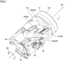
- Fig. 1 is a schematic perspective view illustrating a cutting tool according to a first embodiment of the present disclosure.
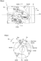
- Figs. 2 and 4 are schematic side views illustrating the cutting tool in Fig. 1 .
- Fig. 3 is a schematic sectional view taken along a line III-III in Fig. 2 .
- Fig. 5 is a schematic sectional view taken along a line V-V in Fig. 4 .
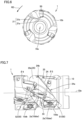
- Fig. 6 is a schematic front view illustrating the cutting tool in Fig. 1 when viewed from a distal end surface side.
- Fig. 7 is a schematic side view illustrating a configuration of the cutting tool in Fig. 1 .
- Fig. 8 is a schematic side view illustrating an axial rake angle of the cutting tool in Fig. 1 .
- Fig. 9 is a schematic side view illustrating the axial rake angle of the cutting tool in Fig. 1 .
- a cutting tool 1 includes a main body 10 and at least four cutting inserts 50.
- Main body 10 has a substantially cylindrical shape.
- Main body 10 is rotatable around a rotation axis 10a.
- Main body 10 has a distal end surface 10b, a rear end surface 10c, and a side surface 10e.
- Rear end surface 10c is located on an opposite side to distal end surface 10b.
- Side surface 10e is an outer peripheral surface that connects distal end surface 10b and rear end surface 10c.
- a plurality of spiral grooves 20 are formed on side surface 10e of main body 10. Specifically, a first groove 20a, a second groove 20b, and a third groove 20c are formed on side surface 10e. Second groove 20b is adjacent to a rear side of main body 10 in a rotation direction RD at intervals when viewed from first groove 20a. Third groove 20c is adjacent to a front side of main body 10 in rotation direction RD at intervals when viewed from first groove 20a. In cutting tool 1 of Figs. 1 to 9 , three grooves 20 are formed in main body 10. However, a number of grooves 20 may be at least four or two.
- At least four cutting inserts 50 are disposed in each of first groove 20a, second groove 20b, and third groove 20c. Inside first groove 20a, at least four cutting inserts 50 include a first cutting insert 51 and a second cutting insert 52 that are disposed third or later from the side of distal end surface 10b of main body 10.
- first cutting insert 51 is located on the side of most rear end surface 10c in at least four cutting inserts 50.
- Second cutting insert 52 is located closer to the side of distal end surface 10b than first cutting insert 51.
- second cutting insert 52 is a cutting insert disposed second from the side of rear end surface 10c.
- a plurality of installation surfaces on which cutting insert 50 is installed are formed on the inner surface of first groove 20a.
- the plurality of installation surfaces may be a planar shape.
- the plurality of installation surfaces are formed so as to face the front side in rotation direction RD of the main body 10 in first groove 20a.
- a first installation surface 10da is formed in a region on the side of rear end surface 10c of first groove 20a.
- First cutting insert 51 is installed on first installation surface 10da of main body 10.
- a fixing hole 2 that is a screw hole is made in first installation surface 10da. Fixing hole 2 is made so as to extend in a direction (circumferential direction) along rotation direction RD of main body 10.
- a through-hole into which a fixing screw 30 is inserted is made in first cutting insert 51.
- First cutting insert 51 is disposed on first installation surface 10da such that the through-hole and fixing hole 2 overlap each other.
- Fixing screw 30 is inserted into and fixed to fixing hole 2 through the through-hole of first cutting insert 51. In this manner, first cutting insert 51 is fixed to first installation surface 10da by fixing screw 30.
- a second installation surface 10db is formed on the side of distal end surface 10b with respect to first installation surface 10da.
- Second cutting insert 52 is installed on second installation surface 10db of main body 10.
- Fig. 3 is a schematic sectional view illustrating cutting tool 1 in a first section that passes through a center 2a of first installation surface 10da and is perpendicular to rotation axis 10a.
- a length from first installation surface 10da to second groove 20b in the circumferential direction along rotation direction RD of main body 10 is set to a first length L1.
- a section that passes through center 2a of first installation surface 10da and is perpendicular to rotation axis 10a is considered.
- an intersection between a semi-straight line that passes through center 2a of first installation surface 10da and extends toward the outside of side surface 10e with rotation axis 10a as a start point and the outermost periphery of a trajectory of side surface 10e when main body 10 rotates about rotation axis 10a is set to a start point 10ea.
- Center 2a is a center point of fixing hole 2 on first installation surface 10da.
- an intersection between a line segment connecting an intersection line (intersection 20ba) between the side wall of second groove 20b (side wall on the side of first groove 20a) and side surface 10e of main body 10 and rotation axis 10a and the outermost periphery of the trajectory of side surface 10e is set to an end point 10eb.
- a length along side surface 10e from start point 10ea to end point 10eb is set to first length L1.
- an angle (central angle ⁇ 1) formed by a line segment connecting rotation axis 10a and center 2a and a line segment connecting rotation axis 10a and intersection 20ba may be used in the cross section.
- Fig. 5 is a schematic sectional view illustrating cutting tool 1 in a second section that passes through center 2a of second installation surface 10db and is perpendicular to rotation axis 10a.
- a length from second installation surface 10db to second groove 20b in the circumferential direction along rotation direction RD of main body 10 is set to a second length L2.
- a section that passes through center 2a of second installation surface 10db and is perpendicular to rotation axis 10a is considered.
- an intersection between a semi-straight line that passes through center 2a of second installation surface 10db and extends toward the outside of side surface 10e with rotation axis 10a as the start point and the outermost periphery of the trajectory of side surface 10e when main body 10 rotates about rotation axis 10a is set to start point 10ea.
- Center 2a is a center point of fixing hole 2 on second installation surface 10db.
- an intersection between a line segment connecting an intersection line (intersection 20ba) between the side wall of second groove 20b (side wall on the side of first groove 20a) and side surface 10e of main body 10 and rotation axis 10a and the outermost periphery of the trajectory of side surface 10e is set to an end point 10eb.
- a length along side surface 10e from start point 10ea to end point 10eb is set to second length L2.
- an angle (central angle ⁇ 2) formed by the line segment connecting rotation axis 10a and center 2a and the line segment connecting rotation axis 10a and intersection 20ba may be used in the cross section.
- first length L1 is longer than second length L2.
- Central angle ⁇ 1 is larger than central angle ⁇ 2.
- first groove 20a intersects distal end surface 10b.
- an edge 21 of first groove 20a in distal end surface 10b has a curved shape protruding toward the side of rotation axis 10a.
- edge 21 includes a first region 21a and a second region 21b.
- First region 21a is located on the side close to the plurality of installation surfaces 10d inside first groove 20a.
- Second region 21b is located farther from the plurality of installation surfaces 10d inside first groove 20a than first region 21a.
- first region 21a is located on the side close to the plurality of cutting inserts 50 arranged in first groove 20a.
- Second region 21b is located on the opposite side of the plurality of cutting inserts 50 when viewed from first region 21a.
- a curvature of first region 21a is larger than a curvature of second region 21b.
- First region 21a is disposed in the region closer to rotation axis 10a than second region 21b.
- the shape of edge 21 has a curvature corresponding to a certain point of edge 21.
- the shape of first region 21a may have substantially the same curvature with respect to all points of first region 21a.
- the shape of first region 21a may have different curvatures corresponding to points on first region 21a.
- the shape of second region 21b may have substantially the same curvature with respect to all points of second region 21b.
- the shape of second region 21b may have different curvatures corresponding to points on second region 21b.
- the "curvature" of first region 21a means a range of values of curvature corresponding to all points on first region 21a.
- the "curvature” of second region 21b means a range of values of curvature corresponding to all points on second region 21b.
- Fig. 7 is a schematic side view illustrating cutting tool 1 when viewed from a direction that is perpendicular to rotation axis 10a and is parallel to second installation surface 10db. As illustrated in Fig. 7 , the direction in which the plurality of cutting inserts 50 are arranged in one groove 20 in cutting tool 1 is different from the extending direction of a sidewall upper end 24 on the front side in rotation direction RD of cutting insert 50 in groove 20. From a different point of view, cutting tool 1 described above has the following features.
- a center 10daa of first installation surface 10da on which first cutting insert 51 is disposed is specified.
- Center 10daa may be center 2a of fixing hole 2 of first installation surface 10da in Fig. 3 .
- a center 10dba of second installation surface 10db on which second cutting insert 52 is disposed is specified.
- Center 10dba may be center 2a of fixing hole 2 of second installation surface 10db in Fig. 5 .
- An angle formed by a line segment 55 connecting center 10daa of first installation surface 10da and center 10dba of second installation surface 10db and rotation axis 10a is set to an insert disposition angle ⁇ 4.
- a first point 24a having the same position in the direction along rotation axis 10a as center 10daa of first installation surface 10da is specified at sidewall upper end 24 of first groove 20a located on the front side in the rotation direction RD of first installation surface 10da.
- Second point 24b having the same position in the direction along the rotation axis 10a as center 10dba of second installation surface 10db is specified.
- An angle formed by a line segment 25 connecting first point 24a and second point 24b and rotation axis 10a is set to a groove angle ⁇ 3. Groove angle ⁇ 3 is larger than insert disposition angle ⁇ 4.
- Fig. 8 is a schematic side view illustrating cutting tool 1 when viewed from the direction that is perpendicular to rotation axis 10a and is parallel to first installation surface 10da.
- Fig. 9 is a schematic side view illustrating cutting tool 1 when viewed from the direction that is perpendicular to rotation axis 10a and is parallel to second installation surface 10db.
- the distance between the plurality of cutting inserts 50 and sidewall upper end 24 of groove 20 decreases toward rear end surface 10c of main body 10. From a different point of view, in cutting tool 1 described above, the distance from first installation surface 10da to sidewall upper end 24 is different from the distance from second installation surface 10db to sidewall upper end 24. That is, as illustrated in Fig.
- the shortest distance from center 10daa of first installation surface 10da to sidewall upper end 24 of first groove 20a located on the front side in rotation direction RD of main body 10 with respect to first installation surface 10da is set to a first width W1.
- the shortest distance from center 10dba of second installation surface 10db to sidewall upper end 24 of first groove 20a is set to a second width W2.
- First width W1 is smaller than second width W2.
- cutting tool 1 includes a third cutting insert 53 that is disposed inside third groove 20c and disposed so as to have a position overlapping first cutting insert 51 in the direction along rotation axis 10a.
- cutting tool 1 includes a fourth cutting insert 54 that is disposed inside third groove 20c and disposed so as to have a position overlapping second cutting insert 52 in the direction along rotation axis 10a.
- cutting tool 1 includes a fifth cutting insert 56 that is disposed inside second groove 20b and disposed so as to have a position overlapping first cutting insert 51 in the direction along rotation axis 10a.
- cutting tool 1 includes a sixth cutting insert 57 that is disposed inside second groove 20b and disposed so as to have a position overlapping second cutting insert 52 in the direction along rotation axis 10a.
- the relationship (corresponding to the relationship between first length L1 and second length L2) between the lengths of the portions of main body 10 adjacent to third cutting insert 53 and fourth cutting insert 54 that are disposed in third groove 20c is the same as the relationship between the lengths of the portions of main body 10 adjacent to first cutting insert 51 and second cutting insert 52 that are disposed in first groove 20a.
- the relationship (corresponding to the relationship between first length L1 and second length L2) between the lengths of the portions of main body 10 adjacent to fifth cutting insert 56 and sixth cutting insert 57 that are disposed in second groove 20b is the same as the relationship between the lengths of the portions of main body 10 adjacent to first cutting insert 51 and second cutting insert 52 that are disposed in first groove 20a.
- each of the plurality of cutting inserts 50 includes a rake surface 50b facing the front side in rotation direction RD in main body 10 and a flank surface 50c continuous to rake surface 50b on the side of side surface 10e of main body 10.
- Each of the ridgelines of the rake surface 50b and the flank surface 50c is a cutting edge 50a.
- an angle formed between a tangent on the side of distal end surface 10b of cutting edge 50a of second cutting insert 52 and rotation axis 10a may be set to a second axial rake angle ⁇ 6.
- first axial rake angle ⁇ 5 is smaller than second axial rake angle ⁇ 6.
- cutting tool 1 the length from first installation surface 10da on which first cutting insert 51 is disposed to second groove 20b in the circumferential direction along rotation direction RD of main body 10 is set to first length L1.
- the length from second installation surface 10db on which second cutting insert 52 is disposed to second groove 20b in the circumferential direction is set to second length L2.
- Cutting tool 1 is configured such that first length L1 is longer than second length L2.
- the volume of the portion (portion of main body 10 supporting first cutting insert 51 from the rear side in rotation direction RD of main body 10) of main body 10 supporting first cutting insert 51 can be made larger than the volume of the portion of main body 10 supporting second cutting insert 52.
- the rigidity of main body 10 can be enhanced by increasing the volume of main body 10 as compared with the case where first groove 20a and second groove 20b have substantially the same width over the entire extending direction.
- the chatter vibration during the cutting can be prevented.
- groove angle ⁇ 3 is larger than insert disposition angle ⁇ 4.
- sidewall upper end 24 of first groove 20a comes closer to the sides of first cutting insert 51 and second cutting insert 52 toward rear end surface 10c of main body 10.
- the width of first groove 20a becomes narrower toward rear end surface 10c.
- the volume of the portion of main body 10 supporting first cutting insert 51 can be easily made larger than the volume of the portion of main body 10 supporting second cutting insert 52.
- the rigidity of main body 10 can be enhanced.
- the shortest distance from center 10daa of first installation surface 10da to sidewall upper end 24 of first groove 20a located on the front side in rotation direction RD of main body 10 with respect to first installation surface 10da is set to first width W1.
- the shortest distance from center 10dba of second installation surface 10db to sidewall upper end 24 of first groove 20a is set to second width W2.
- First width W1 is smaller than second width W2.
- the width (first width W1) of first groove 20a in the portion where first cutting insert 51 is disposed is smaller than the width (second width W2) of first groove 20a in the portion where second cutting insert 52 is disposed.
- the volume of the portion of main body 10 supporting first cutting insert 51 can be easily made larger than the volume of the portion of main body 10 supporting second cutting insert 52.
- the rigidity of main body 10 can be enhanced.
- third groove 20c is formed in side surface 10e of main body 10.
- Third groove 20c is adjacent to the front side in rotation direction RD of main body 10 when viewed from first groove 20a.
- Cutting tool 1 includes third cutting insert 53 that is disposed inside third groove 20c and disposed so as to have the position overlapping first cutting insert 51 in the direction along rotation axis 10a.
- Cutting tool 1 includes fourth cutting insert 54 that is disposed inside third groove 20c and disposed so as to have the position overlapping second cutting insert 52 in the direction along rotation axis 10a.
- the volume of the portion of main body 10 supporting third cutting insert 53 can be made larger than the volume of the portion of main body 10 supporting fourth cutting insert 54.
- the rigidity of main body 10 can be enhanced.
- first axial rake angle ⁇ 5 with respect to rake surface 50b of first cutting insert 51 is smaller than second axial rake angle ⁇ 6 with respect to rake surface 50b of second cutting insert 52.
- chips flow easily to the side of distal end surface 10b of main body 10 by reducing first axial rake angle ⁇ 5 of first cutting insert 51 located on the side of rear end surface 10c in first groove 20a, and as a result, generation of burrs can be prevented.
- the chips are difficult to clog in the region on the side of rear end surface 10c in first groove 20a, the generation of the burrs can be prevented while the generation of the chip clogging is prevented.
- edge 21 of first groove 20a on distal end surface 10b has a curved shape protruding toward rotation axis 10a.
- the curvature of first region 21a in edge 21 is larger than the curvature of second region 21b.
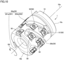
- Fig. 10 is a schematic perspective view illustrating a cutting tool according to a second embodiment of the present disclosure.
- Figs. 11 and 13 are schematic side views illustrating the cutting tool in Fig. 10 .
- Fig. 12 is a schematic sectional view taken along a line XII-XII in Fig. 11 .
- Fig. 14 is a schematic sectional view taken along a line XIV-XIV in Fig. 13 .
- Fig. 15 is a schematic front view illustrating the cutting tool in Fig. 10 when viewed from the distal end surface side.
- Cutting tool 1 in Figs. 10 to 15 basically has the same configuration as the cutting tool 1 in Figs. 1 to 9 , but differs from cutting tool 1 in Figs. 1 to 9 in the shape of groove 20 in main body 10, the structure of cutting insert 50 disposed in groove 20, and the method for fixing cutting insert 50 to main body 10. The details will be described below.
- the plurality of spiral grooves 20 are formed on side surface 10e of main body 10.
- Each of the plurality of grooves 20 is separated into a portion (distal end side groove 201) on the side of distal end surface 10b of main body 10 and a rear end side groove 202 disposed at an interval from the distal end side groove.
- a first groove 20a, a second groove 20b, and a third groove 20c are formed on side surface 10e.
- First groove 20a includes a distal end side groove 201a and a rear end side groove 202a.
- three grooves 20 are formed in main body 10, and the number of grooves 20 may be at least four or two.
- At least four cutting inserts 50 are disposed in each of first groove 20a, second groove 20b, and third groove 20c. Specifically, for example, one cutting insert 50 is disposed in distal end side groove 201a of first groove 20a. Four cutting inserts 50 are disposed in rear end side groove 202a of first groove 20a. The number of cutting inserts 50 disposed in rear end side groove 202a may be greater than or equal to five or less than or equal to three. The number of cutting inserts 50 disposed in distal end side groove 201a may be at least two. Inside first groove 20a, at least four cutting inserts 50 include a first cutting insert 51 and a second cutting insert 52 that are disposed third or later from the side of distal end surface 10b of main body 10.
- first cutting insert 51 is located closest to the side of rear end surface 10c in the rear end side groove 202a among at least four cutting inserts 50.
- Second cutting insert 52 is located closer to the side of distal end surface 10b than first cutting insert 51.
- second cutting insert 52 is the cutting insert disposed second from the side of rear end surface 10c and fourth from the side of distal end surface 10b.
- a plurality of installation surfaces on which cutting insert 50 is installed are formed on the inner surface of first groove 20a.
- the plurality of installation surfaces 10d are formed so as to face the radial outside of main body 10 in the first groove 20 a.
- first installation surface 10da is formed in the region on the side of rear end surface 10c of first groove 20a.
- First installation surface 10da is disposed so as to face the radially outside of main body 10.
- First cutting insert 51 is installed on first installation surface 10da of main body 10.
- a fixing hole 2 that is a screw hole is made in first installation surface 10da.
- Fixing hole 2 is formed so as to extend in the direction (radial direction) toward rotation axis 10a of main body 10.
- a through-hole into which a fixing screw 30 is inserted is made in first cutting insert 51.
- First cutting insert 51 is disposed on first installation surface 10da such that the through-hole and fixing hole 2 overlap each other.
- Fixing screw 30 is inserted into and fixed to fixing hole 2 through the through-hole of first cutting insert 51.
- first cutting insert 51 is fixed to first installation surface 10da by fixing screw 30 disposed so as to extend in the radial direction.
- a second installation surface 10db is formed on the side of distal end surface 10b with respect to first installation surface 10da. Similarly to first installation surface 10da, second installation surface 10db is also disposed so as to face the radial outside of main body 10. Second cutting insert 52 is installed on second installation surface 10db of main body 10. The method for fixing second cutting insert 52 to second installation surface 10db is similar to the method for fixing first cutting insert 51 to first installation surface 10da.
- Fig. 12 is a schematic sectional view illustrating cutting tool 1 in a first section that passes through center 2a of first installation surface 10da and is perpendicular to rotation axis 10a.
- the length from first installation surface 10da to second groove 20b in the circumferential direction along rotation direction RD of main body 10 is set to first length L1.
- a section that passes through center 2a of first installation surface 10da and is perpendicular to rotation axis 10a is considered.
- an intersection between a semi-straight line that passes through center 2a of first installation surface 10da and extends toward the outside of side surface 10e with rotation axis 10a as a start point and the outermost periphery of a trajectory of side surface 10e when main body 10 rotates about rotation axis 10a is set to a start point 10ea.
- Center 2a is a center point of fixing hole 2 on first installation surface 10da.
- an intersection between a line segment connecting an intersection line (intersection 20ba) between the side wall of second groove 20b (side wall on the side of first groove 20a) and side surface 10e of main body 10 and rotation axis 10a and the outermost periphery of the trajectory of side surface 10e is set to an end point 10eb.
- a length along side surface 10e from start point 10ea to end point 10eb is set to first length L1.
- an angle (central angle ⁇ 1) formed by a line segment connecting rotation axis 10a and center 2a and a line segment connecting rotation axis 10a and intersection 20ba may be used in the cross section.
- Fig. 14 is a schematic sectional view illustrating cutting tool 1 in a second section that passes through center 2a of second installation surface 10db and is perpendicular to rotation axis 10a.
- the length from second installation surface 10db to second groove 20b in the circumferential direction along rotation direction RD of main body 10 is set to second length L2.
- a section that passes through center 2a of second installation surface 10db and is perpendicular to rotation axis 10a is considered.
- an intersection between a semi-straight line that passes through center 2a of second installation surface 10db and extends toward the outside of side surface 10e with rotation axis 10a as the start point and the outermost periphery of the trajectory of side surface 10e when main body 10 rotates about rotation axis 10a is set to start point 10ea.
- Center 2a is a center point of fixing hole 2 on second installation surface 10db.
- an intersection between a line segment connecting an intersection line (intersection 20ba) between the side wall of second groove 20b (side wall on the side of first groove 20a) and side surface 10e of main body 10 and rotation axis 10a and the outermost periphery of the trajectory of side surface 10e is set to an end point 10eb.
- a length along side surface 10e from start point 10ea to end point 10eb is set to second length L2.
- the angle (central angle ⁇ 2) formed by the line segment connecting rotation axis 10a and center 2a and the line segment connecting rotation axis 10a and intersection 20ba may be used in the cross section.
- first length L1 is longer than second length L2.
- Central angle ⁇ 1 is larger than central angle ⁇ 2.
- distal end side groove 201a of first groove 20a intersects distal end surface 10b.
- edge 21 of first groove 20a (distal end side groove 201a) in distal end surface 10b includes a curved portion protruding toward the side of rotation axis 10a.
- edge 21 includes a first region 21a and a second region 21b.
- First region 21a is located on the side close to the plurality of installation surfaces 10d inside first groove 20a.
- Second region 21b is located farther from the plurality of installation surfaces 10d inside first groove 20a than first region 21a.
- first region 21a is located on the side close to the plurality of cutting inserts 50 arranged in first groove 20a.
- First region 21a has a curved shape protruding toward the side of rotation axis 10a.
- Second region 21b is located on the opposite side of the plurality of cutting inserts 50 installed in first groove 20a when viewed from first region 21a.
- Second region 21b has a substantially linear shape.
- a curvature of first region 21a is larger than a curvature of second region 21b.
- First region 21a includes a portion closer to rotation axis 10a than second region 21b.
- cutting tool 1 includes third cutting insert 53 that is disposed inside third groove 20c and disposed so as to have the position overlapping first cutting insert 51 in the direction along rotation axis 10a.
- cutting tool 1 includes fourth cutting insert 54 that is disposed inside third groove 20c and disposed so as to have the position overlapping second cutting insert 52 in the direction along rotation axis 10a.
- cutting tool 1 includes fifth cutting insert 56 that is disposed inside second groove 20b and disposed so as to have the position overlapping first cutting insert 51 in the direction along rotation axis 10a.
- cutting tool 1 includes sixth cutting insert 57 that is disposed inside second groove 20b and disposed so as to have the position overlapping second cutting insert 52 in the direction along rotation axis 10a.
- the relationship (corresponding to the relationship between first length L1 and second length L2) between the lengths of the portions of main body 10 adjacent to third cutting insert 53 and fourth cutting insert 54 that are disposed in third groove 20c is the same as the relationship between the lengths of the portions of main body 10 adjacent to first cutting insert 51 and second cutting insert 52 that are disposed in first groove 20a.
- the relationship (corresponding to the relationship between first length L1 and second length L2) between the lengths of the portions of main body 10 adjacent to fifth cutting insert 56 and sixth cutting insert 57 that are disposed in second groove 20b is the same as the relationship between the lengths of the portions of main body 10 adjacent to first cutting insert 51 and second cutting insert 52 that are disposed in first groove 20a.
- Cutting tool 1 in Figs. 10 to 15 can also obtain the same effects as those of cutting tool 1 in Figs. 1 to 9 .
- NVX5080 manufactured by DMG Mori Seiki Co., Ltd., spindle size BBT50
- S50C classified as a carbon steel material S-C material according to the Japanese Industrial Standard (JIS) G4051:2016 was used as a material of the workpiece.
- a square bar was used as the workpiece such that sufficient rigidity can be ensured during cutting.
- the size of the workpiece was 85 mm ⁇ 100 mm ⁇ 300 mm. The workpiece was fixed by holding the side surface with a vice.
- a shank type tool having a tool diameter of 32 mm ⁇ , an effective blade length of 35 mm, the number of effective blades of 3, the total number of blades of 12, and a shank diameter of 32 mm ⁇ was used as the tool.
- a general-purpose cutting insert having a model number AOMT11T308PEER-G manufactured by Sumitomo Electric Hard Metal Co., Ltd. was used as the cutting insert.
- the tool of the example has the configuration in Figs. 1 to 9 .
- a tool of a comparative example a tool having the same configuration as the tool of the above example except that central angle ⁇ 1 in Fig. 3 and central angle ⁇ 2 in Fig. 5 are the same was used.
- Fig. 16 is a schematic diagram illustrating a test method. As illustrated in Fig. 16 , tests cutting workpieces 100 with the tools of the example and the comparative example were performed. As cutting conditions, a rotation speed was set to 150 m/min, a feed amount was set to 0.1 mm/blade, and an axial cutting amount 101 was set to 30 mm. The initial value of radial cutting amount 102 was set to 5 mm, and the initial value was increased by 5 mm until the chatter vibration was generated. A tool protrusion length was 60 mm from the holder.
- a downcutting method As a cutting method, a downcutting method was adopted as illustrated in Fig. 16 . An oil supply method (coolant supply method) during cutting was dry.
- the existence of generation of high sound was used as a criterion. It was determined that the chatter vibration was generated when the high sound was generated.
- the tool of the example and the tool of the comparative example were used to compare the radial cutting amounts at which the chatter vibration was generated.
- the chatter vibration was not generated when the radial cutting amounts were 5 mm, 10 mm, and 15 mm. However, when the radial cut amount was 20 mm, the chatter vibration was generated. In addition, when the radial cut amount was 25 mm, the chatter vibration was markedly generated.
- the chatter vibration was not generated when the radial cutting amounts were 5 mm, 10 mm, 15 mm, and 20 mm.
- the radial cut amount was 25 mm
- the chatter vibration was generated.
- the radial cut amount was 30 mm
- the chatter vibration was markedly generated.
- the tool of the example has the larger radial cutting amount that can be applied without generating the chatter vibration than the tool of the comparative example, it was illustrated that a chatter resistance is high.
- the same vertical machining center as in the example 1 was used.
- the workpiece having the same material and shape as those of the workpiece used in the example 1 was used as the workpiece.
- a shank type tool having a tool diameter of 25 mm ⁇ and a shank diameter of 25 mm ⁇ was used.
- the rotation speed was set to 200 m/min
- the feed amount was set to 0.1 mm/blade
- the axial cutting amount was set to 15 mm
- the radial cutting amount was set to 2 mm.
- the tool protrusion length was 63 mm from the holder.
- the downcutting method was adopted similarly to the example 1.
- the oil supply method at the time of cutting was dry.
- the workpiece was cut using the tool 1 and the tool 2 under the above cutting conditions. Then, the size of the burr on the upper surface of the workpiece was compared.
- 1 cutting tool, 2: fixing hole, 2a, 10daa, 10dba: center, 10: main body, 10a: rotation axis, 10b: distal end surface, 10c: rear end surface, 10d: installation surface, 10da: first installation surface, 10db: second installation surface, 10e: side surface, 10ea: start point, 10eb: end point, 20: groove, 20a: first groove, 20b: second groove, 20ba: intersection, 20c: third groove, 21: edge, 21a: first region, 21b: second region, 24: side wall upper end, 24a: first point, 24b: second point, 25, 55: line segment, 30: fixing screw, 50: cutting insert, 50a: cutting edge, 50b: rake surface, 50c: flank surface, 51: first cutting insert, 52: second cutting insert, 53: third cutting insert, 54: fourth cutting insert, 56: fifth cutting insert, 57: sixth cutting insert, 100: workpiece, 101: axial cutting amount, 102: radial cutting amount, 201,
Landscapes
- Engineering & Computer Science (AREA)
- Mechanical Engineering (AREA)
- Milling Processes (AREA)
Abstract
Description
- The present disclosure relates to a cutting tool.
- Conventionally, there has been known a cutting tool including a rotatable main body and a plurality of cutting inserts disposed on wall surfaces of chip discharge grooves formed on an outer periphery of the main body (for example, see
Japanese Patent Laying-Open No. 2016-190274 - PTL 1:
Japanese Patent Laying-Open No. 2016-190274 - A cutting tool according to one aspect of the present disclosure is a cutting tool rotatable about a rotation axis, and includes a main body. The main body includes a distal end surface, a rear end surface, and a side surface. The side surface is continuous to the distal end surface. The rear end surface is continuous to the side surface and is located on the side opposite to the distal end surface in a direction along the rotation axis. A spiral first groove and a spiral second groove are formed on the side surface of the main body. The second groove is adjacent to the rear side in a rotation direction of the main body when viewed from the first groove. The first groove has at least four installation surfaces inside the first groove. The at least four installation surfaces are used to install a cutting insert. The at least four installation surfaces include a first installation surface and a second installation surface that are disposed third or later from the distal end surface side of the main body. The first installation surface is located on a most rear end surface side among the at least four installation surfaces. The second installation surface is located closer to a distal end surface side with respect to the first installation surface. The at least four installation surfaces have fixing holes fixing the cutting insert, respectively. In the at least four installation surfaces, a center of each fixing hole is set to a center of each of the at least four installation surfaces. In a first section that passes through the center of the first installation surface and is perpendicular to the rotation axis, an intersection of a side surface and a semi-straight line that passes through the center of the first installation surface and extends toward the outside of the side surface with the rotation axis as a start point is set to a first start point. In the first section, an intersection between the side wall of the second groove on the first groove side and the side surface is set to a first end point. A length of the side surface of the main body from the first start point to the first end point in the first section is set to a first length. In a second section that passes through the center of the second installation surface and is perpendicular to the rotation axis, an intersection of the side surface and a semi-straight line that passes through the center of the second installation surface and extends toward the outside of the side surface with the rotation axis as a start point is set to a second start point. In the second section, an intersection between the side wall of the second groove on the first groove side and the side surface is set to a second end point. A length of the side surface of the main body from the second start point to the second end point in the second section is set to a second length. In this case, the first length is longer than the second length.
-
-
Fig. 1 is a schematic perspective view illustrating a cutting tool according to a first embodiment of the present disclosure. -
Fig. 2 is a schematic side view illustrating the cutting tool inFig. 1 . -
Fig. 3 is a schematic sectional view taken along a line III-III inFig. 2 . -
Fig. 4 is a schematic side view illustrating the cutting tool inFig. 1 . -
Fig. 5 is a schematic sectional view taken along a line V-V inFig. 4 . -
Fig. 6 is a schematic front view illustrating the cutting tool inFig. 1 when viewed from a distal end surface side. -
Fig. 7 is a schematic side view illustrating a configuration of the cutting tool inFig. 1 . -
Fig. 8 is a schematic side view illustrating an axial rake angle of the cutting tool inFig. 1 . -
Fig. 9 is a schematic side view illustrating the axial rake angle of the cutting tool inFig. 1 . -
Fig. 10 is a schematic perspective view illustrating a cutting tool according to a second embodiment of the present disclosure. -
Fig. 11 is a schematic side view illustrating the cutting tool inFig. 10 . -
Fig. 12 is a schematic sectional view taken along a line XII-XII inFig. 11 . -
Fig. 13 is a schematic side view illustrating the cutting tool inFig. 10 . -
Fig. 14 is a schematic sectional view taken along a line XIV-XIV inFig. 13 . -
Fig. 15 is a schematic front view illustrating the cutting tool inFig. 10 when viewed from the distal end surface side. -
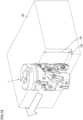
Fig. 16 is a schematic diagram illustrating a test method. - In a conventional cutting tool, vibration (what is called chatter vibration) during cutting is prevented by adjusting disposition of the cutting insert. However, there is a limit to the prevention of the chatter vibration by adjusting the disposition of the cutting insert.
- The present disclosure has been made to solve the above problem. More specifically, the present invention provides a cutting tool capable of preventing the chatter vibration during the cutting.
- According to the cutting tool of the present disclosure, the chatter vibration during the cutting can be prevented.
- An embodiment of the present disclosure will first be described.
- (1) A cutting tool according to one aspect of the present disclosure is a cutting tool rotatable about a rotation axis, and includes a main body. The main body includes a distal end surface, a rear end surface, and a side surface. The side surface is continuous to the distal end surface. The rear end surface is continuous to the side surface and is located on the side opposite to the distal end surface in a direction along the rotation axis. A spiral first groove and a spiral second groove are formed on the side surface of the main body. The second groove is adjacent to the rear side in a rotation direction of the main body when viewed from the first groove. The first groove has at least four installation surfaces inside the first groove. The at least four installation surfaces are used to install a cutting insert. The at least four installation surfaces include a first installation surface and a second installation surface that are disposed third or later from the distal end surface side of the main body. The first installation surface is located on a most rear end surface side among the at least four installation surfaces. The second installation surface is located closer to a distal end surface side with respect to the first installation surface. The at least four installation surfaces have fixing holes fixing the cutting insert, respectively. In the at least four installation surfaces, a center of each fixing hole is set to a center of each of the at least four installation surfaces. In a first section that passes through the center of the first installation surface and is perpendicular to the rotation axis, an intersection of a side surface and a semi-straight line that passes through the center of the first installation surface and extends toward the outside of the side surface with the rotation axis as a start point is set to a first start point. In the first section, an intersection between the side wall of the second groove on the first groove side and the side surface is set to a first end point. A length of the side surface of the main body from the first start point to the first end point in the first section is set to a first length. In a second section that passes through the center of the second installation surface and is perpendicular to the rotation axis, an intersection of the side surface and a semi-straight line that passes through the center of the second installation surface and extends toward the outside of the side surface with the rotation axis as a start point is set to a second start point. In the second section, an intersection between the side wall of the second groove on the first groove side and the side surface is set to a second end point. A length of the side surface of the main body from the second start point to the second end point in the second section is set to a second length. In this case, the first length is longer than the second length.
At this point, chip clogging is difficult to generate toward the rear end surface side of the first groove. That is, because a bottom surface of the workpiece is on the distal end surface side, a space in which the chip generated from the cutting insert is discharged is relatively small. Regarding the cutting insert second from the distal end surface side in the first groove, because a portion holding the cutting insert on the distal end surface side exists in the main body, a space in which the chip is discharged is relatively small. For this reason, the first and second cutting inserts from the distal end surface side are likely to be clogged with the chip. On the other hand, with respect to the cutting insert disposed third or later from the distal end surface side in the first groove, even when capacity of the space in which the chip is discharged is about the same as capacity of the space related to the cutting insert on the distal end surface side described above, sometimes the chip accumulate downward (on the distal end surface side) due to gravity. For this reason, the chip is easily clogged toward the distal end surface side of the main body. In addition, the surface (upper surface) of the workpiece is located on the rear end surface side of the first groove, and a sufficient space can be secured behind the surface. For this reason, the chip is relatively less likely to be clogged on the rear end surface side of the first groove than on the distal end surface side. Thus, the width of the groove can be made smaller in a region closer to the rear end surface in the first groove and the second groove. As a result, the first length of the first cutting insert located on the rear end surface side of the first groove can be longer than the second length of the second cutting insert. That is, a volume of the portion of the main body supporting the first cutting insert can be made larger than a volume of the portion of the main body supporting the second cutting insert. As a result, the rigidity of the main body can be enhanced by increasing the volume of the main body as compared with a case where the first groove and the second groove have substantially the same width over the entire extending direction. Thus, the chatter vibration during the cutting can be prevented. - (2) (1) In the cutting tool, when the main body is viewed from a direction that is perpendicular to the rotation axis and is parallel to the second installation surface, an angle formed by a line segment connecting the center of the first installation surface and the center of the second installation surface and the rotation axis may be set as an insert disposition angle. When the main body is viewed from the direction that is perpendicular to the rotation axis and is parallel to the second installation surface, an angle formed by the rotation axis and a line segment connecting a first point and a second point at a sidewall upper end of the first groove located on the front side in the rotation direction with respect to the first installation surface may be set to a groove angle, the center of the first installation surface and a position of the first point in the direction along the rotation axis are the same and the center of the second installation surface and a position of the second point in the direction along the rotation axis are the same. In this case, the groove angle may be larger than the insert disposition angle.
In this case, the sidewall upper end of the first groove comes closer to the first cutting insert and the second cutting insert side toward the rear end surface side of the main body. As a result, the width of the first groove becomes narrower toward the rear end surface side. Thus, the volume of the portion of the main body supporting the first cutting insert can be easily made larger than the volume of the portion of the main body supporting the second cutting insert. - (3) In the cutting tool of (1) or (2), when the main body is viewed from a direction that is perpendicular to the rotation axis and is parallel to the first installation surface, a shortest distance from the center of the first installation surface to the sidewall upper end of the first groove located on a front side in a rotation direction of the main body with respect to the first installation surface may be set to a first width. When the main body is viewed from a direction that is perpendicular to the rotation axis and is parallel to the second installation surface, the shortest distance from the center of the second installation surface to the sidewall upper end of the first groove may be set to a second width. The first width may be smaller than the second width.
In this case, the width (first width) of the first groove in the portion where the first cutting insert is disposed is smaller than the width (second width) of the first groove in the portion where the second cutting insert is disposed. Thus, the volume of the portion of the main body supporting the first cutting insert can be easily made larger than the volume of the portion of the main body supporting the second cutting insert. - (4) The cutting tool of (1) to (3) may further include at least four cutting inserts that are disposed inside the first groove and disposed on at least four installation surfaces, respectively. The at least four cutting inserts may include a first cutting insert and a second cutting insert. The first cutting insert may be installed on the first installation surface. The second cutting insert may be installed on the second installation surface. Each of the at least four cutting inserts may have a rake surface facing the front side in the rotation direction in the main body and a flank surface continuous to the rake surface on the side surface side of the main body. Each of the ridgelines of the rake surface and the flank surface may be a cutting edge. When the main body is viewed from the direction that is perpendicular to the rotation axis and is parallel to the first installation surface, an angle formed between the rotation axis and a tangent on the distal end surface side of the cutting edge of the first cutting insert may be set to a first axial rake angle. When the main body is viewed from the direction that is perpendicular to the rotation axis and is parallel to the second installation surface, an angle formed between the rotation axis and a tangent on the distal end surface side of the cutting edge of the second cutting insert may be set to a second axial rake angle. In this case, the first axial rake angle may be smaller than the second axial rake angle.
In this case, the chip flows easily to the distal end surface side of the main body by reducing the axial rake angle of the first cutting insert located on the rear end surface side in the first groove, and as a result, the generation of burrs can be prevented. Furthermore, the chips are difficult to clog in the region on the rear end surface side in the first groove, the generation of the burrs can be prevented while the generation of the chip clogging is prevented. - (5) In the cutting tools of (1) to (4), the first groove may intersect the distal end surface. The edge of the first groove in the distal end surface may have a curved shape protruding toward the rotation axis side. The edge may include a first region located on a side closer to the at least four installation surfaces and a second region located on a side farther from the at least four installation surfaces than the first region. The curvature of the first region may be larger than the curvature of the second region.
- In this case, on the distal end surface side of the main body, the chips generated by cutting of the cutting insert can be quickly flowed along the inner surface of the first groove. For this reason, the generation of the chip clogging can be prevented on the distal end surface side of the main body.
- With reference to the drawings, an embodiment of the present disclosure will be described in detail. In the following drawings, the same or corresponding component is designated by the same reference numeral, and the overlapping description will be omitted.
-
Fig. 1 is a schematic perspective view illustrating a cutting tool according to a first embodiment of the present disclosure.Figs. 2 and4 are schematic side views illustrating the cutting tool inFig. 1 .Fig. 3 is a schematic sectional view taken along a line III-III inFig. 2 .Fig. 5 is a schematic sectional view taken along a line V-V inFig. 4 .Fig. 6 is a schematic front view illustrating the cutting tool inFig. 1 when viewed from a distal end surface side.Fig. 7 is a schematic side view illustrating a configuration of the cutting tool inFig. 1 .Fig. 8 is a schematic side view illustrating an axial rake angle of the cutting tool inFig. 1 .Fig. 9 is a schematic side view illustrating the axial rake angle of the cutting tool inFig. 1 . - As illustrated in
Figs. 1 to 9 , acutting tool 1 according to one aspect of the present disclosure includes amain body 10 and at least four cutting inserts 50.Main body 10 has a substantially cylindrical shape.Main body 10 is rotatable around arotation axis 10a.Main body 10 has adistal end surface 10b, arear end surface 10c, and aside surface 10e.Rear end surface 10c is located on an opposite side todistal end surface 10b.Side surface 10e is an outer peripheral surface that connectsdistal end surface 10b andrear end surface 10c. - A plurality of
spiral grooves 20 are formed onside surface 10e ofmain body 10. Specifically, afirst groove 20a, asecond groove 20b, and athird groove 20c are formed onside surface 10e.Second groove 20b is adjacent to a rear side ofmain body 10 in a rotation direction RD at intervals when viewed fromfirst groove 20a.Third groove 20c is adjacent to a front side ofmain body 10 in rotation direction RD at intervals when viewed fromfirst groove 20a. In cuttingtool 1 ofFigs. 1 to 9 , threegrooves 20 are formed inmain body 10. However, a number ofgrooves 20 may be at least four or two. - At least four cutting
inserts 50 are disposed in each offirst groove 20a,second groove 20b, andthird groove 20c. Insidefirst groove 20a, at least four cuttinginserts 50 include afirst cutting insert 51 and asecond cutting insert 52 that are disposed third or later from the side ofdistal end surface 10b ofmain body 10. - As illustrated in
Fig. 1 and the like, first cuttinginsert 51 is located on the side of mostrear end surface 10c in at least four cutting inserts 50. Second cuttinginsert 52 is located closer to the side ofdistal end surface 10b than first cuttinginsert 51. In cuttingtool 1,second cutting insert 52 is a cutting insert disposed second from the side ofrear end surface 10c. - A plurality of installation surfaces on which cutting
insert 50 is installed are formed on the inner surface offirst groove 20a. The plurality of installation surfaces may be a planar shape. The plurality of installation surfaces are formed so as to face the front side in rotation direction RD of themain body 10 infirst groove 20a. Specifically, a first installation surface 10da is formed in a region on the side ofrear end surface 10c offirst groove 20a. First cuttinginsert 51 is installed on first installation surface 10da ofmain body 10. Specifically, a fixinghole 2 that is a screw hole is made in first installation surface 10da. Fixinghole 2 is made so as to extend in a direction (circumferential direction) along rotation direction RD ofmain body 10. A through-hole into which a fixingscrew 30 is inserted is made infirst cutting insert 51. First cuttinginsert 51 is disposed on first installation surface 10da such that the through-hole and fixinghole 2 overlap each other. Fixingscrew 30 is inserted into and fixed to fixinghole 2 through the through-hole offirst cutting insert 51. In this manner, first cuttinginsert 51 is fixed to first installation surface 10da by fixingscrew 30. - In
first groove 20a, a second installation surface 10db is formed on the side ofdistal end surface 10b with respect to first installation surface 10da. Second cuttinginsert 52 is installed on second installation surface 10db ofmain body 10. -
Fig. 3 is a schematic sectional view illustratingcutting tool 1 in a first section that passes through acenter 2a of first installation surface 10da and is perpendicular torotation axis 10a. As illustrated inFig. 3 , a length from first installation surface 10da tosecond groove 20b in the circumferential direction along rotation direction RD ofmain body 10 is set to a first length L1. Specifically, a section that passes throughcenter 2a of first installation surface 10da and is perpendicular torotation axis 10a is considered. In the section, an intersection between a semi-straight line that passes throughcenter 2a of first installation surface 10da and extends toward the outside ofside surface 10e withrotation axis 10a as a start point and the outermost periphery of a trajectory ofside surface 10e whenmain body 10 rotates aboutrotation axis 10a is set to a start point 10ea.Center 2a is a center point of fixinghole 2 on first installation surface 10da. In the section, an intersection between a line segment connecting an intersection line (intersection 20ba) between the side wall ofsecond groove 20b (side wall on the side offirst groove 20a) andside surface 10e ofmain body 10 androtation axis 10a and the outermost periphery of the trajectory ofside surface 10e is set to an end point 10eb. In the section, a length alongside surface 10e from start point 10ea to end point 10eb is set to first length L1. As an index indicating the length from start point 10ea to end point 10eb, an angle (central angle θ1) formed by a line segment connectingrotation axis 10a andcenter 2a and a line segment connectingrotation axis 10a and intersection 20ba may be used in the cross section. -
Fig. 5 is a schematic sectional view illustratingcutting tool 1 in a second section that passes throughcenter 2a of second installation surface 10db and is perpendicular torotation axis 10a. As illustrated inFig. 5 , a length from second installation surface 10db tosecond groove 20b in the circumferential direction along rotation direction RD ofmain body 10 is set to a second length L2. Specifically, a section that passes throughcenter 2a of second installation surface 10db and is perpendicular torotation axis 10a is considered. In the section, an intersection between a semi-straight line that passes throughcenter 2a of second installation surface 10db and extends toward the outside ofside surface 10e withrotation axis 10a as the start point and the outermost periphery of the trajectory ofside surface 10e whenmain body 10 rotates aboutrotation axis 10a is set to start point 10ea.Center 2a is a center point of fixinghole 2 on second installation surface 10db. In the section, an intersection between a line segment connecting an intersection line (intersection 20ba) between the side wall ofsecond groove 20b (side wall on the side offirst groove 20a) andside surface 10e ofmain body 10 androtation axis 10a and the outermost periphery of the trajectory ofside surface 10e is set to an end point 10eb. In the section, a length alongside surface 10e from start point 10ea to end point 10eb is set to second length L2. As the index indicating the length from start point 10ea to end point 10eb, an angle (central angle θ2) formed by the line segment connectingrotation axis 10a andcenter 2a and the line segment connectingrotation axis 10a and intersection 20ba may be used in the cross section. - In cutting
tool 1 ofFigs. 1 to 5 , first length L1 is longer than second length L2. Central angle θ1 is larger than central angle θ2. The relationship between the lengths of the portions ofmain body 10 adjacent tofirst cutting insert 51 and second cuttinginsert 52 that are installed infirst groove 20a described above (the relationship between first length L1 and second length L2) also holds for cuttinginserts 50 installed inother grooves 20. - As illustrated in
Figs. 1 and6 , in cuttingtool 1,first groove 20a intersectsdistal end surface 10b. Whendistal end surface 10b is viewed alongrotation axis 10a, anedge 21 offirst groove 20a indistal end surface 10b has a curved shape protruding toward the side ofrotation axis 10a. Specifically, as illustrated inFig. 6 ,edge 21 includes afirst region 21a and asecond region 21b.First region 21a is located on the side close to the plurality ofinstallation surfaces 10d insidefirst groove 20a.Second region 21b is located farther from the plurality ofinstallation surfaces 10d insidefirst groove 20a thanfirst region 21a. From another point of view,first region 21a is located on the side close to the plurality of cutting inserts 50 arranged infirst groove 20a.Second region 21b is located on the opposite side of the plurality of cutting inserts 50 when viewed fromfirst region 21a. A curvature offirst region 21a is larger than a curvature ofsecond region 21b.First region 21a is disposed in the region closer torotation axis 10a thansecond region 21b. - When
distal end surface 10b is viewed alongrotation axis 10a, the shape ofedge 21 has a curvature corresponding to a certain point ofedge 21. The shape offirst region 21a may have substantially the same curvature with respect to all points offirst region 21a. The shape offirst region 21a may have different curvatures corresponding to points onfirst region 21a. Similarly, the shape ofsecond region 21b may have substantially the same curvature with respect to all points ofsecond region 21b. Similarly, the shape ofsecond region 21b may have different curvatures corresponding to points onsecond region 21b. In the present specification, the "curvature" offirst region 21a means a range of values of curvature corresponding to all points onfirst region 21a. Similarly, in the present specification, the "curvature" ofsecond region 21b means a range of values of curvature corresponding to all points onsecond region 21b. -
Fig. 7 is a schematic side view illustratingcutting tool 1 when viewed from a direction that is perpendicular torotation axis 10a and is parallel to second installation surface 10db. As illustrated inFig. 7 , the direction in which the plurality of cutting inserts 50 are arranged in onegroove 20 in cuttingtool 1 is different from the extending direction of a sidewallupper end 24 on the front side in rotation direction RD of cuttinginsert 50 ingroove 20. From a different point of view,cutting tool 1 described above has the following features. - As illustrated in
Fig. 7 , a case wheremain body 10 is viewed from the direction that is perpendicular torotation axis 10a and parallel to the second installation surface 10db will be considered. A center 10daa of first installation surface 10da on which first cuttinginsert 51 is disposed is specified. Center 10daa may be center 2a of fixinghole 2 of first installation surface 10da inFig. 3 . A center 10dba of second installation surface 10db on whichsecond cutting insert 52 is disposed is specified. Center 10dba may be center 2a of fixinghole 2 of second installation surface 10db inFig. 5 . An angle formed by aline segment 55 connecting center 10daa of first installation surface 10da and center 10dba of second installation surface 10db androtation axis 10a is set to an insert disposition angle θ4. - When
main body 10 is viewed from the direction that is perpendicular torotation axis 10a and is parallel to second installation surface 10db, afirst point 24a having the same position in the direction alongrotation axis 10a as center 10daa of first installation surface 10da is specified at sidewallupper end 24 offirst groove 20a located on the front side in the rotation direction RD of first installation surface 10da.Second point 24b having the same position in the direction along therotation axis 10a as center 10dba of second installation surface 10db is specified. An angle formed by aline segment 25 connectingfirst point 24a andsecond point 24b androtation axis 10a is set to a groove angle θ3. Groove angle θ3 is larger than insert disposition angle θ4. -
Fig. 8 is a schematic side view illustratingcutting tool 1 when viewed from the direction that is perpendicular torotation axis 10a and is parallel to first installation surface 10da.Fig. 9 is a schematic side view illustratingcutting tool 1 when viewed from the direction that is perpendicular torotation axis 10a and is parallel to second installation surface 10db. In cuttingtool 1 described above, the distance between the plurality of cutting inserts 50 and sidewallupper end 24 ofgroove 20 decreases towardrear end surface 10c ofmain body 10. From a different point of view, in cuttingtool 1 described above, the distance from first installation surface 10da to sidewallupper end 24 is different from the distance from second installation surface 10db to sidewallupper end 24. That is, as illustrated inFig. 8 , the shortest distance from center 10daa of first installation surface 10da to sidewallupper end 24 offirst groove 20a located on the front side in rotation direction RD ofmain body 10 with respect to first installation surface 10da is set to a first width W1. As illustrated inFig. 9 , the shortest distance from center 10dba of second installation surface 10db to sidewallupper end 24 offirst groove 20a is set to a second width W2. First width W1 is smaller than second width W2. - As illustrated in
Fig. 3 , cuttingtool 1 includes athird cutting insert 53 that is disposed insidethird groove 20c and disposed so as to have a position overlapping first cuttinginsert 51 in the direction alongrotation axis 10a. As illustrated inFig. 5 , cuttingtool 1 includes afourth cutting insert 54 that is disposed insidethird groove 20c and disposed so as to have a position overlapping second cuttinginsert 52 in the direction alongrotation axis 10a. - As illustrated in
Fig. 3 , cuttingtool 1 includes afifth cutting insert 56 that is disposed insidesecond groove 20b and disposed so as to have a position overlapping first cuttinginsert 51 in the direction alongrotation axis 10a. As illustrated inFig. 5 , cuttingtool 1 includes asixth cutting insert 57 that is disposed insidesecond groove 20b and disposed so as to have a position overlapping second cuttinginsert 52 in the direction alongrotation axis 10a. The relationship (corresponding to the relationship between first length L1 and second length L2) between the lengths of the portions ofmain body 10 adjacent tothird cutting insert 53 and fourth cuttinginsert 54 that are disposed inthird groove 20c is the same as the relationship between the lengths of the portions ofmain body 10 adjacent tofirst cutting insert 51 and second cuttinginsert 52 that are disposed infirst groove 20a. The relationship (corresponding to the relationship between first length L1 and second length L2) between the lengths of the portions ofmain body 10 adjacent tofifth cutting insert 56 and sixth cuttinginsert 57 that are disposed insecond groove 20b is the same as the relationship between the lengths of the portions ofmain body 10 adjacent tofirst cutting insert 51 and second cuttinginsert 52 that are disposed infirst groove 20a. - As illustrated in
Figs. 8 and 9 , in cuttingtool 1, each of the plurality of cutting inserts 50 includes arake surface 50b facing the front side in rotation direction RD inmain body 10 and aflank surface 50c continuous to rakesurface 50b on the side ofside surface 10e ofmain body 10. Each of the ridgelines of therake surface 50b and theflank surface 50c is acutting edge 50a. Whenmain body 10 is viewed from the direction that is perpendicular torotation axis 10a and is parallel to first installation surface 10da, an angle formed between a tangent on the side ofdistal end surface 10b of cuttingedge 50a of first cuttinginsert 51 androtation axis 10a may be set to a first axial rake angle θ5. Whenmain body 10 is viewed from the direction that is perpendicular torotation axis 10a and is parallel to second installation surface 10db, an angle formed between a tangent on the side ofdistal end surface 10b of cuttingedge 50a ofsecond cutting insert 52 androtation axis 10a may be set to a second axial rake angle θ6. In this case, first axial rake angle θ5 is smaller than second axial rake angle θ6. - In cutting
tool 1, the length from first installation surface 10da on which first cuttinginsert 51 is disposed tosecond groove 20b in the circumferential direction along rotation direction RD ofmain body 10 is set to first length L1. The length from second installation surface 10db on whichsecond cutting insert 52 is disposed tosecond groove 20b in the circumferential direction is set to second length L2. Cuttingtool 1 is configured such that first length L1 is longer than second length L2. - In this way, the volume of the portion (portion of
main body 10 supporting first cuttinginsert 51 from the rear side in rotation direction RD of main body 10) ofmain body 10 supporting first cuttinginsert 51 can be made larger than the volume of the portion ofmain body 10 supporting second cuttinginsert 52. As a result, the rigidity ofmain body 10 can be enhanced by increasing the volume ofmain body 10 as compared with the case wherefirst groove 20a andsecond groove 20b have substantially the same width over the entire extending direction. Thus, the chatter vibration during the cutting can be prevented. - In cutting
tool 1, as illustrated inFig. 7 , groove angle θ3 is larger than insert disposition angle θ4. In this case, sidewallupper end 24 offirst groove 20a comes closer to the sides offirst cutting insert 51 and second cuttinginsert 52 towardrear end surface 10c ofmain body 10. As a result, the width offirst groove 20a becomes narrower towardrear end surface 10c. Thus, the volume of the portion ofmain body 10 supporting first cuttinginsert 51 can be easily made larger than the volume of the portion ofmain body 10 supporting second cuttinginsert 52. As a result, the rigidity ofmain body 10 can be enhanced. - In cutting
tool 1, as illustrated inFig. 8 , the shortest distance from center 10daa of first installation surface 10da to sidewallupper end 24 offirst groove 20a located on the front side in rotation direction RD ofmain body 10 with respect to first installation surface 10da is set to first width W1. As illustrated inFig. 9 , the shortest distance from center 10dba of second installation surface 10db to sidewallupper end 24 offirst groove 20a is set to second width W2. First width W1 is smaller than second width W2. In this case, the width (first width W1) offirst groove 20a in the portion where first cuttinginsert 51 is disposed is smaller than the width (second width W2) offirst groove 20a in the portion wheresecond cutting insert 52 is disposed. Thus, the volume of the portion ofmain body 10 supporting first cuttinginsert 51 can be easily made larger than the volume of the portion ofmain body 10 supporting second cuttinginsert 52. As a result, the rigidity ofmain body 10 can be enhanced. - In cutting
tool 1,third groove 20c is formed inside surface 10e ofmain body 10.Third groove 20c is adjacent to the front side in rotation direction RD ofmain body 10 when viewed fromfirst groove 20a. Cuttingtool 1 includesthird cutting insert 53 that is disposed insidethird groove 20c and disposed so as to have the position overlapping first cuttinginsert 51 in the direction alongrotation axis 10a. Cuttingtool 1 includes fourth cuttinginsert 54 that is disposed insidethird groove 20c and disposed so as to have the position overlapping second cuttinginsert 52 in the direction alongrotation axis 10a. - In this case, the volume of the portion of
main body 10 supporting third cuttinginsert 53 can be made larger than the volume of the portion ofmain body 10 supporting fourth cuttinginsert 54. Thus, the rigidity ofmain body 10 can be enhanced. - In cutting
tool 1, first axial rake angle θ5 with respect to rakesurface 50b offirst cutting insert 51 is smaller than second axial rake angle θ6 with respect to rakesurface 50b ofsecond cutting insert 52. In this case, chips flow easily to the side ofdistal end surface 10b ofmain body 10 by reducing first axial rake angle θ5 offirst cutting insert 51 located on the side ofrear end surface 10c infirst groove 20a, and as a result, generation of burrs can be prevented. Furthermore, the chips are difficult to clog in the region on the side ofrear end surface 10c infirst groove 20a, the generation of the burrs can be prevented while the generation of the chip clogging is prevented. - In cutting
tool 1, edge 21 offirst groove 20a ondistal end surface 10b has a curved shape protruding towardrotation axis 10a. The curvature offirst region 21a inedge 21 is larger than the curvature ofsecond region 21b. - In this case, on the side of
distal end surface 10b ofmain body 10, the chips generated by cutting of cuttinginsert 50 can be quickly flowed along the inner surface offirst groove 20a. For this reason, the generation of the chip clogging can be prevented on the distal end surface side ofmain body 10. -
Fig. 10 is a schematic perspective view illustrating a cutting tool according to a second embodiment of the present disclosure.Figs. 11 and13 are schematic side views illustrating the cutting tool inFig. 10 .Fig. 12 is a schematic sectional view taken along a line XII-XII inFig. 11 .Fig. 14 is a schematic sectional view taken along a line XIV-XIV inFig. 13 .Fig. 15 is a schematic front view illustrating the cutting tool inFig. 10 when viewed from the distal end surface side. - Cutting
tool 1 inFigs. 10 to 15 basically has the same configuration as thecutting tool 1 inFigs. 1 to 9 , but differs from cuttingtool 1 inFigs. 1 to 9 in the shape ofgroove 20 inmain body 10, the structure of cuttinginsert 50 disposed ingroove 20, and the method for fixing cuttinginsert 50 tomain body 10. The details will be described below. - As illustrated in
Figs. 10 to 15 , the plurality ofspiral grooves 20 are formed onside surface 10e ofmain body 10. Each of the plurality ofgrooves 20 is separated into a portion (distal end side groove 201) on the side ofdistal end surface 10b ofmain body 10 and a rearend side groove 202 disposed at an interval from the distal end side groove. Specifically, afirst groove 20a, asecond groove 20b, and athird groove 20c are formed onside surface 10e.First groove 20a includes a distalend side groove 201a and a rearend side groove 202a. In cuttingtool 1 ofFigs. 10 to 15 , threegrooves 20 are formed inmain body 10, and the number ofgrooves 20 may be at least four or two. - At least four cutting
inserts 50 are disposed in each offirst groove 20a,second groove 20b, andthird groove 20c. Specifically, for example, one cuttinginsert 50 is disposed in distalend side groove 201a offirst groove 20a. Four cutting inserts 50 are disposed in rearend side groove 202a offirst groove 20a. The number of cutting inserts 50 disposed in rearend side groove 202a may be greater than or equal to five or less than or equal to three. The number of cutting inserts 50 disposed in distalend side groove 201a may be at least two. Insidefirst groove 20a, at least four cuttinginserts 50 include afirst cutting insert 51 and asecond cutting insert 52 that are disposed third or later from the side ofdistal end surface 10b ofmain body 10. - As illustrated in
Fig. 10 and the like, first cuttinginsert 51 is located closest to the side ofrear end surface 10c in the rearend side groove 202a among at least four cutting inserts 50. Second cuttinginsert 52 is located closer to the side ofdistal end surface 10b than first cuttinginsert 51. Inillustrated cutting tool 1,second cutting insert 52 is the cutting insert disposed second from the side ofrear end surface 10c and fourth from the side ofdistal end surface 10b. - A plurality of installation surfaces on which cutting
insert 50 is installed are formed on the inner surface offirst groove 20a. The plurality ofinstallation surfaces 10d are formed so as to face the radial outside ofmain body 10 in thefirst groove 20 a. Specifically, as illustrated inFig. 12 , first installation surface 10da is formed in the region on the side ofrear end surface 10c offirst groove 20a. First installation surface 10da is disposed so as to face the radially outside ofmain body 10. First cuttinginsert 51 is installed on first installation surface 10da ofmain body 10. Specifically, a fixinghole 2 that is a screw hole is made in first installation surface 10da. Fixinghole 2 is formed so as to extend in the direction (radial direction) towardrotation axis 10a ofmain body 10. A through-hole into which a fixingscrew 30 is inserted is made infirst cutting insert 51. First cuttinginsert 51 is disposed on first installation surface 10da such that the through-hole and fixinghole 2 overlap each other. Fixingscrew 30 is inserted into and fixed to fixinghole 2 through the through-hole offirst cutting insert 51. In this manner, first cuttinginsert 51 is fixed to first installation surface 10da by fixingscrew 30 disposed so as to extend in the radial direction. - In
first groove 20a, a second installation surface 10db is formed on the side ofdistal end surface 10b with respect to first installation surface 10da. Similarly to first installation surface 10da, second installation surface 10db is also disposed so as to face the radial outside ofmain body 10. Second cuttinginsert 52 is installed on second installation surface 10db ofmain body 10. The method for fixingsecond cutting insert 52 to second installation surface 10db is similar to the method for fixing first cuttinginsert 51 to first installation surface 10da. -
Fig. 12 is a schematic sectional view illustratingcutting tool 1 in a first section that passes throughcenter 2a of first installation surface 10da and is perpendicular torotation axis 10a. As illustrated inFig. 12 , the length from first installation surface 10da tosecond groove 20b in the circumferential direction along rotation direction RD ofmain body 10 is set to first length L1. Specifically, a section that passes throughcenter 2a of first installation surface 10da and is perpendicular torotation axis 10a is considered. In the section, an intersection between a semi-straight line that passes throughcenter 2a of first installation surface 10da and extends toward the outside ofside surface 10e withrotation axis 10a as a start point and the outermost periphery of a trajectory ofside surface 10e whenmain body 10 rotates aboutrotation axis 10a is set to a start point 10ea.Center 2a is a center point of fixinghole 2 on first installation surface 10da. In the section, an intersection between a line segment connecting an intersection line (intersection 20ba) between the side wall ofsecond groove 20b (side wall on the side offirst groove 20a) andside surface 10e ofmain body 10 androtation axis 10a and the outermost periphery of the trajectory ofside surface 10e is set to an end point 10eb. In the section, a length alongside surface 10e from start point 10ea to end point 10eb is set to first length L1. As an index indicating the length from start point 10ea to end point 10eb, an angle (central angle θ1) formed by a line segment connectingrotation axis 10a andcenter 2a and a line segment connectingrotation axis 10a and intersection 20ba may be used in the cross section. -
Fig. 14 is a schematic sectional view illustratingcutting tool 1 in a second section that passes throughcenter 2a of second installation surface 10db and is perpendicular torotation axis 10a. As illustrated inFig. 14 , the length from second installation surface 10db tosecond groove 20b in the circumferential direction along rotation direction RD ofmain body 10 is set to second length L2. Specifically, a section that passes throughcenter 2a of second installation surface 10db and is perpendicular torotation axis 10a is considered. In the section, an intersection between a semi-straight line that passes throughcenter 2a of second installation surface 10db and extends toward the outside ofside surface 10e withrotation axis 10a as the start point and the outermost periphery of the trajectory ofside surface 10e whenmain body 10 rotates aboutrotation axis 10a is set to start point 10ea.Center 2a is a center point of fixinghole 2 on second installation surface 10db. In the section, an intersection between a line segment connecting an intersection line (intersection 20ba) between the side wall ofsecond groove 20b (side wall on the side offirst groove 20a) andside surface 10e ofmain body 10 androtation axis 10a and the outermost periphery of the trajectory ofside surface 10e is set to an end point 10eb. In the section, a length alongside surface 10e from start point 10ea to end point 10eb is set to second length L2. As the index indicating the length from start point 10ea to end point 10eb, the angle (central angle θ2) formed by the line segment connectingrotation axis 10a andcenter 2a and the line segment connectingrotation axis 10a and intersection 20ba may be used in the cross section. - In cutting
tool 1 ofFigs. 10 to 14 , first length L1 is longer than second length L2. Central angle θ1 is larger than central angle θ2. The relationship between the lengths of the portions ofmain body 10 adjacent tofirst cutting insert 51 and second cuttinginsert 52 that are installed infirst groove 20a described above (the relationship between first length L1 and second length L2) also holds for cuttinginserts 50 installed inother grooves 20. - As illustrated in
Figs. 10 and15 , in cuttingtool 1, distalend side groove 201a offirst groove 20a intersectsdistal end surface 10b. Whendistal end surface 10b is viewed alongrotation axis 10a, edge 21 offirst groove 20a (distalend side groove 201a) indistal end surface 10b includes a curved portion protruding toward the side ofrotation axis 10a. Specifically, as illustrated inFig. 15 ,edge 21 includes afirst region 21a and asecond region 21b.First region 21a is located on the side close to the plurality ofinstallation surfaces 10d insidefirst groove 20a.Second region 21b is located farther from the plurality ofinstallation surfaces 10d insidefirst groove 20a thanfirst region 21a. From another point of view,first region 21a is located on the side close to the plurality of cutting inserts 50 arranged infirst groove 20a.First region 21a has a curved shape protruding toward the side ofrotation axis 10a.Second region 21b is located on the opposite side of the plurality of cutting inserts 50 installed infirst groove 20a when viewed fromfirst region 21a.Second region 21b has a substantially linear shape. A curvature offirst region 21a is larger than a curvature ofsecond region 21b.First region 21a includes a portion closer torotation axis 10a thansecond region 21b. - As illustrated in
Fig. 12 , cuttingtool 1 includesthird cutting insert 53 that is disposed insidethird groove 20c and disposed so as to have the position overlapping first cuttinginsert 51 in the direction alongrotation axis 10a. As illustrated inFig. 14 , cuttingtool 1 includes fourth cuttinginsert 54 that is disposed insidethird groove 20c and disposed so as to have the position overlapping second cuttinginsert 52 in the direction alongrotation axis 10a. - As illustrated in
Fig. 12 , cuttingtool 1 includesfifth cutting insert 56 that is disposed insidesecond groove 20b and disposed so as to have the position overlapping first cuttinginsert 51 in the direction alongrotation axis 10a. As illustrated inFig. 14 , cuttingtool 1 includes sixth cuttinginsert 57 that is disposed insidesecond groove 20b and disposed so as to have the position overlapping second cuttinginsert 52 in the direction alongrotation axis 10a. The relationship (corresponding to the relationship between first length L1 and second length L2) between the lengths of the portions ofmain body 10 adjacent tothird cutting insert 53 and fourth cuttinginsert 54 that are disposed inthird groove 20c is the same as the relationship between the lengths of the portions ofmain body 10 adjacent tofirst cutting insert 51 and second cuttinginsert 52 that are disposed infirst groove 20a. The relationship (corresponding to the relationship between first length L1 and second length L2) between the lengths of the portions ofmain body 10 adjacent tofifth cutting insert 56 and sixth cuttinginsert 57 that are disposed insecond groove 20b is the same as the relationship between the lengths of the portions ofmain body 10 adjacent tofirst cutting insert 51 and second cuttinginsert 52 that are disposed infirst groove 20a. - Cutting
tool 1 inFigs. 10 to 15 can also obtain the same effects as those of cuttingtool 1 inFigs. 1 to 9 . - A test was conducted regarding the effect of preventing chatter vibration.
- For the test, a vertical machining center (NVX5080 manufactured by DMG Mori Seiki Co., Ltd., spindle size BBT50) was used.
- S50C classified as a carbon steel material S-C material according to the Japanese Industrial Standard (JIS) G4051:2016 was used as a material of the workpiece. A square bar was used as the workpiece such that sufficient rigidity can be ensured during cutting. The size of the workpiece was 85 mm×100 mm×300 mm. The workpiece was fixed by holding the side surface with a vice.
- A shank type tool having a tool diameter of 32 mm ϕ, an effective blade length of 35 mm, the number of effective blades of 3, the total number of blades of 12, and a shank diameter of 32 mm ϕ was used as the tool. A general-purpose cutting insert having a model number AOMT11T308PEER-G manufactured by Sumitomo Electric Hard Metal Co., Ltd. was used as the cutting insert. The tool of the example has the configuration in
Figs. 1 to 9 . As a tool of a comparative example, a tool having the same configuration as the tool of the above example except that central angle θ1 inFig. 3 and central angle θ2 inFig. 5 are the same was used. -
Fig. 16 is a schematic diagram illustrating a test method. As illustrated inFig. 16 ,tests cutting workpieces 100 with the tools of the example and the comparative example were performed. As cutting conditions, a rotation speed was set to 150 m/min, a feed amount was set to 0.1 mm/blade, and anaxial cutting amount 101 was set to 30 mm. The initial value ofradial cutting amount 102 was set to 5 mm, and the initial value was increased by 5 mm until the chatter vibration was generated. A tool protrusion length was 60 mm from the holder. - As a cutting method, a downcutting method was adopted as illustrated in
Fig. 16 . An oil supply method (coolant supply method) during cutting was dry. - As a criterion for determining existence of the chatter vibration, the existence of generation of high sound was used as a criterion. It was determined that the chatter vibration was generated when the high sound was generated.
- Under the above cutting conditions, the tool of the example and the tool of the comparative example were used to compare the radial cutting amounts at which the chatter vibration was generated.
- In the tool of the comparative example, the chatter vibration was not generated when the radial cutting amounts were 5 mm, 10 mm, and 15 mm. However, when the radial cut amount was 20 mm, the chatter vibration was generated. In addition, when the radial cut amount was 25 mm, the chatter vibration was markedly generated.
- On the other hand, in the tool of the example, the chatter vibration was not generated when the radial cutting amounts were 5 mm, 10 mm, 15 mm, and 20 mm. When the radial cut amount was 25 mm, the chatter vibration was generated. In addition, when the radial cut amount was 30 mm, the chatter vibration was markedly generated.
- As described above, because the tool of the example has the larger radial cutting amount that can be applied without generating the chatter vibration than the tool of the comparative example, it was illustrated that a chatter resistance is high.
- A test was conducted on the relationship between the generation of the burrs and the axial rake angle.
- For the test, the same vertical machining center as in the example 1 was used. In addition, the workpiece having the same material and shape as those of the workpiece used in the example 1 was used as the workpiece.
- As the tool, a shank type tool having a tool diameter of 25 mm ϕ and a shank diameter of 25 mm ϕ was used. A
tool 1 in which the axial rake angle (axial rake) of the cutting insert processing an upper surface portion of the workpiece was 16° and atool 2 in which the axial rake angle was -1° were prepared. - A general-purpose cutting insert having a model number AOMT11T308PEER-G manufactured by Sumitomo Electric Hard Metal Co., Ltd. was used as the cutting insert.
- As cutting conditions, the rotation speed was set to 200 m/min, the feed amount was set to 0.1 mm/blade, the axial cutting amount was set to 15 mm, and the radial cutting amount was set to 2 mm. The tool protrusion length was 63 mm from the holder.
- As the cutting method, the downcutting method was adopted similarly to the example 1. The oil supply method at the time of cutting was dry.
- The workpiece was cut using the
tool 1 and thetool 2 under the above cutting conditions. Then, the size of the burr on the upper surface of the workpiece was compared. - The generation of the visually-checked burrs was prevented in the case of using the
tool 2 than in the case of using thetool 1. Thus, it was illustrated that the burrs were prevented by reducing the axial rake angle. - It should be understood that the first and second embodiments disclosed herein are illustrative in all respects and are not restrictive. The basic scope of the present invention is defined not by the first and second embodiments but by the claims, and is intended to include meanings equivalent to the claims and all modifications within the scope.
- 1: cutting tool, 2: fixing hole, 2a, 10daa, 10dba: center, 10: main body, 10a: rotation axis, 10b: distal end surface, 10c: rear end surface, 10d: installation surface, 10da: first installation surface, 10db: second installation surface, 10e: side surface, 10ea: start point, 10eb: end point, 20: groove, 20a: first groove, 20b: second groove, 20ba: intersection, 20c: third groove, 21: edge, 21a: first region, 21b: second region, 24: side wall upper end, 24a: first point, 24b: second point, 25, 55: line segment, 30: fixing screw, 50: cutting insert, 50a: cutting edge, 50b: rake surface, 50c: flank surface, 51: first cutting insert, 52: second cutting insert, 53: third cutting insert, 54: fourth cutting insert, 56: fifth cutting insert, 57: sixth cutting insert, 100: workpiece, 101: axial cutting amount, 102: radial cutting amount, 201, 201a: distal end-side groove, 202, 202a: rear end-side groove, L1: first length, L2: second length, RD: rotation direction, W1: first width, W2: second width, θ1, θ2: central angle, θ3: groove angle, θ4: insert disposition angle, θ5: first axial rake angle, θ6: second axial rake angle
Claims (5)
- A cutting tool rotatable about a rotation axis, the cutting tool comprising a main body that includes a distal end surface, a side surface continuous to the distal end surface, and a rear end surface that is continuous to the side surface and is located on a side opposite to the distal end surface in a direction along the rotation axis,wherein a spiral first groove and a spiral second groove are formed on the side surface of the main body,the second groove is adjacent to a rear side in a rotation direction of the main body when viewed from the first groove,the first groove has at least four installation surfaces inside the first groove,the at least four installation surfaces are used to install a cutting insert,the at least four installation surfaces include a first installation surface and a second installation surface that are disposed third or later from the distal end surface side of the main body,the first installation surface is located on a most rear end surface side among the at least four installation surfaces,the second installation surface is located closer to the distal end surface than the first installation surface,the at least four installation surfaces have fixing holes fixing the cutting insert, respectively,a center of each of the fixing holes on the at least four installation surfaces is set to a center of each of the at least four installation surfaces, andwhen an intersection of the side surface and a semi-straight line is set to a first start point, the semi-straight line passing through the center of the first installation surface and extending toward an outside of the side surface with the rotation axis as a start point, in a first section that passes through the center of the first installation surface and is perpendicular to the rotation axis,when an intersection between a side wall of the second groove on the first groove side and the side surface in the first section is set to a first end point,when a length of the side surface of the main body from the first start point to the first end point in the first section is set to a first length,when an intersection of the side surface and a semi-straight line is set to a second start point, the semi-straight line passing through the center of the second installation surface and extends toward an outside of the side surface with the rotation axis as a start point, in a second section passing through the center of the second installation surface and perpendicular to the rotation axis,when an intersection between a side wall of the second groove on the first groove side and the side surface in the second section is set to a second end point, andwhen a length of the side surface of the main body from the second start point to the second end point in the second section is set to a second length,the first length is longer than the second length.
- The cutting tool according to claim 1, wherein when the main body is viewed from a direction that is perpendicular to the rotation axis and is parallel to the second installation surface,an angle formed by the rotation axis and a line segment connecting the center of the first installation surface and the center of the second installation surface is set to an insert disposition angle, andan angle formed by the rotation axis and a line segment connecting a first point and a second point at a sidewall upper end of the first groove located on a front side in the rotation direction with respect to the first installation surface is set to a groove angle, the center of the first installation surface and a position of the first point in a direction along the rotation axis are identical and the center of the second installation surface and a position of the second point in the direction along the rotation axis are identical, andthe groove angle is larger than the insert disposition angle.
- The cutting tool according to claim 1 or 2, wherein a shortest distance from the center of the first installation surface to a sidewall upper end of the first groove is set to a first width, the sidewall upper end of the first groove being located on the front side in the rotation direction of the main body with respect to the first installation surface, when the main body is viewed from a direction that is perpendicular to the rotation axis and is parallel to the first installation surface, anda shortest distance from the center of the second installation surface to the sidewall upper end of the first groove is set to a second width when the main body is viewed from a direction perpendicular to the rotation axis and parallel to the second installation surface, andthe first width is smaller than the second width.
- The cutting tool according to any one of claims 1 to 3, further comprising at least four cutting inserts that are disposed inside the first groove and are disposed on the at least four installation surfaces, respectively,wherein the at least four cutting inserts include a first cutting insert and a second cutting insert,the first cutting insert is installed on the first installation surface,the second cutting insert is installed on the second installation surface,each of the at least four cutting inserts includes a rake surface facing the front side in the rotation direction in the main body and a flank surface continuous to the rake surface on the side surface side of the main body,a ridgeline of each of the rake surface and the flank surface is a cutting edge,an angle formed between a tangent on the distal end surface side of the cutting edge of the first cutting insert and the rotation axis is set to a first axial rake angle when the main body is viewed from a direction that is perpendicular to the rotation axis and is parallel to the first installation surface, andan angle formed by a tangent on the distal end surface side of the cutting edge of the second cutting insert and the rotation axis is set to a second axial rake angle when the main body is viewed from a direction that is perpendicular to the rotation axis and is parallel to the second installation surface, andthe first axial rake angle is smaller than the second axial rake angle.
- The cutting tool according to any one of claims 1 to 4, wherein the first groove intersects the distal end surface,an edge of the first groove in the distal end surface has a curved shape protruding toward the rotation axis side,the edge includes a first region located on a side closer to the at least four installation surfaces and a second region located on a side farther from the at least four installation surfaces than the first region, anda curvature of the first region is larger than a curvature of the second region.
Applications Claiming Priority (1)
| Application Number | Priority Date | Filing Date | Title |
|---|---|---|---|
| PCT/JP2021/014488 WO2022215114A1 (en) | 2021-04-05 | 2021-04-05 | Cutting tool |
Publications (2)
| Publication Number | Publication Date |
|---|---|
| EP4321285A1 true EP4321285A1 (en) | 2024-02-14 |
| EP4321285A4 EP4321285A4 (en) | 2024-06-19 |
Family
ID=81260069
Family Applications (1)
| Application Number | Title | Priority Date | Filing Date |
|---|---|---|---|
| EP21935922.1A Pending EP4321285A4 (en) | 2021-04-05 | 2021-04-05 | Cutting tool |
Country Status (5)
| Country | Link |
|---|---|
| US (1) | US12358060B2 (en) |
| EP (1) | EP4321285A4 (en) |
| JP (1) | JP7052176B1 (en) |
| CN (1) | CN116867593B (en) |
| WO (1) | WO2022215114A1 (en) |
Families Citing this family (4)
| Publication number | Priority date | Publication date | Assignee | Title |
|---|---|---|---|---|
| PL3795316T3 (en) * | 2019-09-19 | 2026-03-23 | Ledermann Gmbh & Co. Kg | Tool head of the machining tool |
| USD1065274S1 (en) * | 2020-08-24 | 2025-03-04 | Sumitomo Electric Hardmetal Corp. | Pressing tool for cutting tool |
| USD1123001S1 (en) | 2020-09-01 | 2026-04-21 | Sumitomo Electric Hardmetal Corp. | Cutting tool |
| JP2025059719A (en) | 2023-09-29 | 2025-04-10 | 三菱マテリアル株式会社 | Cutting inserts and indexable end mills |
Family Cites Families (27)
| Publication number | Priority date | Publication date | Assignee | Title |
|---|---|---|---|---|
| JPH0131370Y2 (en) * | 1985-05-30 | 1989-09-26 | ||
| JPH0141527Y2 (en) | 1985-06-21 | 1989-12-07 | ||
| US4681485A (en) * | 1986-02-25 | 1987-07-21 | Gte Valeron Corporation | End mill cutting tool and indexable insert therefor |
| US4790693A (en) * | 1987-02-06 | 1988-12-13 | Ingersoll Cutting Tool Company | Interfitting on-edge inserts for milling cutters |
| JPH0179510U (en) * | 1987-11-11 | 1989-05-29 | ||
| JP2878443B2 (en) * | 1990-11-16 | 1999-04-05 | 東芝タンガロイ株式会社 | Indexable end mill |
| JPH081426A (en) * | 1994-06-15 | 1996-01-09 | Toshiba Tungaloy Co Ltd | Roughing end mill |
| US5913644A (en) * | 1998-04-20 | 1999-06-22 | Kennametal Inc. | Helical mill having multiple flutes with differing rake angles |
| US6976811B1 (en) | 2000-10-04 | 2005-12-20 | Kennametal Inc. | Milling cutter |
| US7399146B2 (en) * | 2003-09-29 | 2008-07-15 | Kennametal Inc. | Rotary cutting tool having irregular insert orientation |
| SE526769C2 (en) | 2003-12-16 | 2005-11-01 | Sandvik Intellectual Property | Milling tools with overlap planes and a first cut of different length |
| US7753625B2 (en) * | 2005-06-13 | 2010-07-13 | Kennametal Inc. | Helical cutting insert with multiple cutting edges |
| JP5023628B2 (en) * | 2006-09-13 | 2012-09-12 | 三菱マテリアル株式会社 | Roughing end mill |
| US8613574B2 (en) | 2008-02-22 | 2013-12-24 | Kennametal Inc. | Helical milling cutter |
| WO2010100953A1 (en) * | 2009-03-06 | 2010-09-10 | 三菱マテリアル株式会社 | Cutting inset and tool having cutting inserts |
| JP5834518B2 (en) | 2010-06-16 | 2015-12-24 | 三菱日立ツール株式会社 | Replaceable cutting edge rotary cutting tool |
| US8647026B2 (en) * | 2011-11-23 | 2014-02-11 | Kennametal Inc. | Cutting tool with pocket feature for reducing stress |
| JP2014083629A (en) * | 2012-10-23 | 2014-05-12 | Mitsubishi Materials Corp | Tip replaceable cutting tool and tool body of the same |
| US20170197257A1 (en) | 2013-12-25 | 2017-07-13 | Tungaloy Corporation | Indexable rotary cutting tool and tool body |
| EP3147057B1 (en) * | 2014-07-14 | 2022-03-02 | Tungaloy Corporation | Indexable rotary cutting tool |
| US9505066B2 (en) * | 2014-08-01 | 2016-11-29 | Kennametal Inc. | Rotary cutting tool with regrindable cutting inserts |
| AT14369U1 (en) * | 2014-11-24 | 2015-09-15 | Ceratizit Austria Gmbh | Tool for machining |
| JP6587090B2 (en) | 2015-03-30 | 2019-10-09 | 国立大学法人名古屋大学 | Turning tool |
| US10556278B2 (en) * | 2016-08-16 | 2020-02-11 | Kennametal Inc. | Tool body for a shell end mill and cutting tool |
| DE112017007563T5 (en) * | 2017-08-09 | 2020-02-20 | Osg Corporation | Indexable insert tool |
| CN111712344B (en) | 2018-02-26 | 2023-10-27 | 京瓷株式会社 | Cutting tool and method for manufacturing cutting workpiece |
| DE102019127027A1 (en) * | 2019-10-08 | 2021-04-08 | Kennametal Inc. | Cutting tool |
-
2021
- 2021-04-05 EP EP21935922.1A patent/EP4321285A4/en active Pending
- 2021-04-05 WO PCT/JP2021/014488 patent/WO2022215114A1/en not_active Ceased
- 2021-04-05 CN CN202180086256.7A patent/CN116867593B/en active Active
- 2021-04-05 US US17/768,480 patent/US12358060B2/en active Active
- 2021-04-05 JP JP2021576996A patent/JP7052176B1/en active Active
Also Published As
| Publication number | Publication date |
|---|---|
| CN116867593B (en) | 2025-09-19 |
| JP7052176B1 (en) | 2022-04-12 |
| EP4321285A4 (en) | 2024-06-19 |
| US20240293877A1 (en) | 2024-09-05 |
| CN116867593A (en) | 2023-10-10 |
| JPWO2022215114A1 (en) | 2022-10-13 |
| US12358060B2 (en) | 2025-07-15 |
| WO2022215114A1 (en) | 2022-10-13 |
Similar Documents
| Publication | Publication Date | Title |
|---|---|---|
| US12358060B2 (en) | Cutting tool | |
| US8550756B2 (en) | Drill bit for drilling having at least two cutting edges, each with two cutting portions and a non-cutting portion between the two cutting portions | |
| JP6421792B2 (en) | Drill and drill head | |
| JP5365298B2 (en) | Drill inserts and insert drills | |
| JP4976181B2 (en) | Tip placement method for throw-away drills | |
| EP2441543B1 (en) | Drilling tool | |
| JP4965667B2 (en) | drill | |
| EP2181787B1 (en) | End mill | |
| EP2815830A1 (en) | End mill with coolant holes | |
| EP2305406B1 (en) | Cutting tool and cutting method using same | |
| JP5383149B2 (en) | Drill and cutting method | |
| CN112839763B (en) | Oil hole reamer | |
| KR20080051074A (en) | drill | |
| EP2532460A1 (en) | Cutting edge replacement type groove forming tool and end face groove forming method | |
| JP6467049B2 (en) | CUTTING TOOL AND MANUFACTURING METHOD OF CUT WORK | |
| EP4209297A1 (en) | Cutting insert for rotational cutting tool and rotational cutting tool | |
| JP2014083629A (en) | Tip replaceable cutting tool and tool body of the same | |
| JP4815386B2 (en) | 3-flute ball end mill and 4-flute ball end mill | |
| JP7763258B2 (en) | drill | |
| WO2019220778A9 (en) | Cutting insert for drill, and drill | |
| US11548078B2 (en) | Drilling tool | |
| JPWO2023032180A5 (en) | ||
| JP2002166316A (en) | Drilling tool | |
| CN114867575B (en) | Indexable insert cutting tool cage and indexable insert cutting tool | |
| JP6462364B2 (en) | THROW-AWAY TYPE DRILL AND METHOD FOR MANUFACTURING CUTTING PRODUCT USING THE SAME |
Legal Events
| Date | Code | Title | Description |
|---|---|---|---|
| STAA | Information on the status of an ep patent application or granted ep patent |
Free format text: STATUS: THE INTERNATIONAL PUBLICATION HAS BEEN MADE |
|
| PUAI | Public reference made under article 153(3) epc to a published international application that has entered the european phase |
Free format text: ORIGINAL CODE: 0009012 |
|
| STAA | Information on the status of an ep patent application or granted ep patent |
Free format text: STATUS: REQUEST FOR EXAMINATION WAS MADE |
|
| 17P | Request for examination filed |
Effective date: 20230623 |
|
| AK | Designated contracting states |
Kind code of ref document: A1 Designated state(s): AL AT BE BG CH CY CZ DE DK EE ES FI FR GB GR HR HU IE IS IT LI LT LU LV MC MK MT NL NO PL PT RO RS SE SI SK SM TR |
|
| A4 | Supplementary search report drawn up and despatched |
Effective date: 20240523 |
|
| RIC1 | Information provided on ipc code assigned before grant |
Ipc: B23C 5/00 20060101ALI20240516BHEP Ipc: B23C 5/10 20060101AFI20240516BHEP |
|
| DAV | Request for validation of the european patent (deleted) | ||
| DAX | Request for extension of the european patent (deleted) |