EP4321262A1 - Slot die coater and multi-lane double coating apparatus comprising same - Google Patents
Slot die coater and multi-lane double coating apparatus comprising same Download PDFInfo
- Publication number
- EP4321262A1 EP4321262A1 EP22911697.5A EP22911697A EP4321262A1 EP 4321262 A1 EP4321262 A1 EP 4321262A1 EP 22911697 A EP22911697 A EP 22911697A EP 4321262 A1 EP4321262 A1 EP 4321262A1
- Authority
- EP
- European Patent Office
- Prior art keywords
- slot
- concave portion
- die block
- manifold
- coating solution
- Prior art date
- Legal status (The legal status is an assumption and is not a legal conclusion. Google has not performed a legal analysis and makes no representation as to the accuracy of the status listed.)
- Granted
Links
Images




Classifications
-
- B—PERFORMING OPERATIONS; TRANSPORTING
- B05—SPRAYING OR ATOMISING IN GENERAL; APPLYING FLUENT MATERIALS TO SURFACES, IN GENERAL
- B05C—APPARATUS FOR APPLYING FLUENT MATERIALS TO SURFACES, IN GENERAL
- B05C5/00—Apparatus in which liquid or other fluent material is projected, poured or allowed to flow on to the surface of the work
- B05C5/02—Apparatus in which liquid or other fluent material is projected, poured or allowed to flow on to the surface of the work the liquid or other fluent material being discharged through an outlet orifice by pressure, e.g. from an outlet device in contact or almost in contact, with the work
- B05C5/0254—Coating heads with slot-shaped outlet
-
- B—PERFORMING OPERATIONS; TRANSPORTING
- B05—SPRAYING OR ATOMISING IN GENERAL; APPLYING FLUENT MATERIALS TO SURFACES, IN GENERAL
- B05C—APPARATUS FOR APPLYING FLUENT MATERIALS TO SURFACES, IN GENERAL
- B05C11/00—Component parts, details or accessories not specifically provided for in groups B05C1/00 - B05C9/00
- B05C11/10—Storage, supply or control of liquid or other fluent material; Recovery of excess liquid or other fluent material
-
- B—PERFORMING OPERATIONS; TRANSPORTING
- B05—SPRAYING OR ATOMISING IN GENERAL; APPLYING FLUENT MATERIALS TO SURFACES, IN GENERAL
- B05C—APPARATUS FOR APPLYING FLUENT MATERIALS TO SURFACES, IN GENERAL
- B05C11/00—Component parts, details or accessories not specifically provided for in groups B05C1/00 - B05C9/00
- B05C11/10—Storage, supply or control of liquid or other fluent material; Recovery of excess liquid or other fluent material
- B05C11/1044—Apparatus or installations for supplying liquid or other fluent material to several applying apparatus or several dispensing outlets, e.g. to several extrusion nozzles
-
- B—PERFORMING OPERATIONS; TRANSPORTING
- B05—SPRAYING OR ATOMISING IN GENERAL; APPLYING FLUENT MATERIALS TO SURFACES, IN GENERAL
- B05C—APPARATUS FOR APPLYING FLUENT MATERIALS TO SURFACES, IN GENERAL
- B05C5/00—Apparatus in which liquid or other fluent material is projected, poured or allowed to flow on to the surface of the work
- B05C5/02—Apparatus in which liquid or other fluent material is projected, poured or allowed to flow on to the surface of the work the liquid or other fluent material being discharged through an outlet orifice by pressure, e.g. from an outlet device in contact or almost in contact, with the work
- B05C5/027—Coating heads with several outlets, e.g. aligned transversally to the moving direction of a web to be coated
-
- B—PERFORMING OPERATIONS; TRANSPORTING
- B05—SPRAYING OR ATOMISING IN GENERAL; APPLYING FLUENT MATERIALS TO SURFACES, IN GENERAL
- B05C—APPARATUS FOR APPLYING FLUENT MATERIALS TO SURFACES, IN GENERAL
- B05C9/00—Apparatus or plant for applying liquid or other fluent material to surfaces by means not covered by any preceding group, or in which the means of applying the liquid or other fluent material is not important
- B05C9/06—Apparatus or plant for applying liquid or other fluent material to surfaces by means not covered by any preceding group, or in which the means of applying the liquid or other fluent material is not important for applying two different liquids or other fluent materials, or the same liquid or other fluent material twice, to the same side of the work
-
- H—ELECTRICITY
- H01—ELECTRIC ELEMENTS
- H01M—PROCESSES OR MEANS, e.g. BATTERIES, FOR THE DIRECT CONVERSION OF CHEMICAL ENERGY INTO ELECTRICAL ENERGY
- H01M10/00—Secondary cells; Manufacture thereof
- H01M10/42—Methods or arrangements for servicing or maintenance of secondary cells or secondary half-cells
- H01M10/4235—Safety or regulating additives or arrangements in electrodes, separators or electrolyte
-
- H—ELECTRICITY
- H01—ELECTRIC ELEMENTS
- H01M—PROCESSES OR MEANS, e.g. BATTERIES, FOR THE DIRECT CONVERSION OF CHEMICAL ENERGY INTO ELECTRICAL ENERGY
- H01M4/00—Electrodes
- H01M4/02—Electrodes composed of, or comprising, active material
- H01M4/04—Processes of manufacture in general
- H01M4/0402—Methods of deposition of the material
- H01M4/0404—Methods of deposition of the material by coating on electrode collectors
-
- Y—GENERAL TAGGING OF NEW TECHNOLOGICAL DEVELOPMENTS; GENERAL TAGGING OF CROSS-SECTIONAL TECHNOLOGIES SPANNING OVER SEVERAL SECTIONS OF THE IPC; TECHNICAL SUBJECTS COVERED BY FORMER USPC CROSS-REFERENCE ART COLLECTIONS [XRACs] AND DIGESTS
- Y02—TECHNOLOGIES OR APPLICATIONS FOR MITIGATION OR ADAPTATION AGAINST CLIMATE CHANGE
- Y02E—REDUCTION OF GREENHOUSE GAS [GHG] EMISSIONS, RELATED TO ENERGY GENERATION, TRANSMISSION OR DISTRIBUTION
- Y02E60/00—Enabling technologies; Technologies with a potential or indirect contribution to GHG emissions mitigation
- Y02E60/10—Energy storage using batteries
Definitions
- the present disclosure relates to a slot die coater, and more particularly, to a slot die coater capable of simultaneously forming an electrode active material coating layer and an insulating coating layer on both side portions of the electrode active material coating layer on an electrode current collector, and a multi-lane double coating device including the slot die coater.
- a secondary battery in general, includes a battery case, and an electrode assembly accommodated together with an electrolyte in the battery case.
- the electrode assembly has a structure in which a positive electrode, a separator, and a negative electrode are alternately stacked.
- the positive electrode and the negative electrode of the electrode assembly respectively include current collectors formed of aluminum (Al)-foil and copper (Cu)-foil.
- a positive electrode active material and a negative electrode active material are respectively applied to the positive electrode current collector and the negative electrode current collector, and an electrode tab is connected to a portion to which an active material is not applied, that is, a non-coated portion.
- a positive active material layer and a negative active material layer should be precisely coated on current collectors.
- a slot coating process is usually performed.
- FIG. 1 is a cross-sectional view illustrating a general slot die coater for performing a slot coating process.
- an electrode active material slurry discharged from the slot die coater 30 is applied to a current collector 20 transported by a coating roll 10.
- the electrode active material slurry discharged from the slot die coater 30 is widely applied to one surface of the current collector 20 to form an electrode active material coating layer.
- the slot die coater 30 includes two die blocks 32, 36 and a slot 36 is formed between the two die blocks 32, 34.
- An electrode active material slurry supplied from a feed unit (not shown) may be accommodated in a manifold 38, and then may be discharged through a discharge port 39 communicating with the slot 36 to form an electrode active material coating layer.
- Reference numerals 32a and 34a respectively denote die lips that are front ends of the die blocks 32, 34.
- a coating width of the electrode active material coating layer coated on the current collector 20 is determined by a width of the slot 36.
- various coating widths may be achieved by changing a shim plate 35 for determining a width of the slot 36 and an inner space of the manifold 38.
- a polyolefin-based material commonly used as a separator has a disadvantage in that it thermally shrinks to its original size at high temperature due to material properties. Accordingly, when a temperature of a secondary battery greatly increases, the possibility of an electrical short circuit between positive and negative electrode current collectors increases as the separator shrinks.
- a ceramic-based insulating coating solution may be simultaneously coated on both sides of the electrode active material coating layer, which is a so-called multi-lane double coating process.
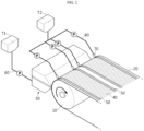
- a multi-line double coating device includes the slot die coater 30, one slurry tank T1, one slurry supply pipe 60, one pump P provided on a path of the slurry supply pipe 60, four insulating liquid dies 70 for insulating liquid coating, one insulating liquid tank T2, four insulating liquid supply pipes 80, and four pumps P provided on paths of the insulating liquid supply pipes 80.
- the multi-lane double coating device of the prior art has a problem in that, because the number of insulating coating solution dies 70, insulating liquid supply pipes 80, and pumps P is determined according to the number of coating lanes on the current collector, an equipment layout is complicated and equipment investment cost increase as the number of coating lanes increases. Accordingly, there is a need to improve an existing multi-lane double coating device.
- the present disclosure is designed to solve the problems of the related art, and therefore the present disclosure is directed to providing a slot die coater capable of simultaneously forming an electrode active material coating layer and an insulating coating layer on both side portions of the electrode active material coating layer on an electrode current collector by improving a shim plate.
- the present disclosure is directed to reducing an equipment layout and investment cost by providing a multi-lane double coating device including the slot die coater.
- the first concave portion may extend from an end of the shim plate facing the discharge port in a direction away from the discharge port by a length enough to communicate with the first manifold
- the second concave portion may extend from an end of the shim plate in a direction away from the discharge port by a length enough to communicate with the second manifold.
- the first concave portion may be recessed by a certain thickness compared to other portions of the first surface, and the second concave portion may be recessed by a certain thickness compared to other portions of the second surface.
- the slot may include a slurry slot provided between the lower die block and the first concave portion of the first surface, and an insulating coating solution slot provided between the upper die block and the second concave portion of the second surface.
- the first concave portion may be provided in two or more spaced apart at a predetermined interval along the width direction of the shim plate.
- the two or more first concave portions may communicate with the first manifold so that the electrode active material slurry moves along the slurry slot to be applied to the current collector through the discharge port.
- the second concave portion located on both sides of the first concave portion may communicate with the second manifold so that the insulating coating solution moves along the insulating coating solution slot to be applied to the current collector through the discharge port.
- At least one of edge portions of the first concave portion and the second concave portion adjacent to each other is chamfered.
- the lower die block may include a first feed unit configured to form a path for supplying the electrode active material slurry to the first manifold, and the upper die block may include a second feed unit configured to form a path for supplying the insulating coating solution to the second manifold.
- a multi-lane double coating device including the slot die coater, an electrode slurry storage tank in which the electrode active material slurry is stored, one slurry supply pipe connected to the lower die block of the slot die coater from the electrode slurry storage tank, a coating solution storage tank in which the insulating coating solution is stored, and one coating solution supply pipe connected to the upper die block of the slot die coater from the coating solution storage tank.
- a slot die coater capable of simultaneously coating an electrode active material coating layer and an insulating coating layer on both side portions of the electrode active material coating layer on an electrode current collector.
- a slot through which an electrode active material slurry may flow and a slot through which an insulating coating solution may flow are formed between a lower die block and an upper die block due to one shim plate. Accordingly, according to the slot die coater of the present disclosure, the efficiency and yield of a multi-lane double coating processing may be improved.
- a multi-lane double coating device that has a simpler equipment layout than that of the prior art and may reduce equipment investment cost.
- the present disclosure may have various other effects, which will be described in each embodiment, or descriptions of effects that may be easily inferred by one of ordinary skill in the art will be omitted.
- a first manifold in which an insulating coating solution is accommodated is provided in an upper die block
- a second manifold in which an electrode active material slurry is accommodated is provided in a lower die block.
- the terms "upper” and “lower” are for convenience of explanation, and may vary according to a position of a target object or an observer.
- an upper die block of FIG. 7 may be interpreted as a lower die block and a lower die block of FIG. 7 may be interpreted as an upper die block.
- a first manifold in which an insulating coating solution is accommodated is provided in an upper die block and a second manifold in which an electrode active material slurry is accommodated is provided in a lower die block.
- FIG. 3 is a view schematically illustrating a configuration of a multi-lane double coating device, according to an embodiment of the present disclosure.
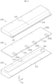
- FIG. 4 is a schematic exploded perspective view illustrating a slot die coater, according to an embodiment of the present disclosure.
- a multi-lane double coating device is a device for simultaneously coating an electrode active material slurry 40 and an insulating coating solution 50 on a current collector 20, and includes a slot die coater 100, an electrode slurry storage tank 200, a slurry supply pipe 300, a coating solution storage tank 400, and one coating solution supply pipe 500.
- the electrode slurry storage tank 200 and the slot die coater 100 are connected to one slurry supply pipe 300, and the coating solution storage tank 400 and the slot die coater 100 are also connected to one coating solution supply pipe 500, regardless of the number of lanes in which the electrode active material slurry 40 and the insulating coating solution 50 are applied to the current collector 20 (in an X direction).
- the multi-lane double coating device according to the present disclosure has a simple piping configuration and layout. Also, according to the present disclosure, because the electrode active material slurry 40 and the insulating coating solution 50 are simultaneously discharged through one slot die coater 100 and applied to the current collector 20, a coating process speed and yield are higher than those in the prior art.
- the slot die coater 100 that is a main element of the multi-lane double coating device according to the present disclosure includes a lower die block 110, an upper die block 120, and a shim plate 130 configured to integrally form two types of slots between the lower die block 110 and the upper die block 120.
- the two types of slots refer to two types of paths through which the electrode active material slurry 40 and the insulating coating solution 50 may respectively flow toward a discharge port 102, between the lower die block 110 and the upper die block 120.
- the slot die coater 100 is provided so that a direction (X direction) in which the electrode active material slurry 40 is discharged is almost horizontal (e.g., about ⁇ 5°).
- a direction in which the electrode active material slurry 40 is discharged is almost horizontal (e.g., about ⁇ 5°).
- the present disclosure is not limited thereto.
- the slot die coater 100 may be configured as a vertical die in which a direction in which the electrode active material slurry 40 is discharged is upward (Z direction).
- a slot is formed between the lower die block 110 and the upper die block 120 facing each other.
- the shim plate 130 is provided between the lower die block 110 and the upper die block 120 to form a gap, and thus, the slot through which the electrode active material slurry 40 or the insulating coating solution 50 may flow is formed.
- the slot (see FIGS. 7 and 8 ) of the slot die coater 100 of the present disclosure includes a slurry slot 101a through which the electrode active material slurry 40 may flow and an insulating coating solution slot 101b through which the insulating coating solution 50 may flow.
- the lower die block 110 includes a first manifold 111 having a certain depth, longitudinally extending in a width direction (Y direction) of the lower die block 110, and communicating with the slurry slot 101a. Also, the lower die block 110 includes a first feed unit 113 that forms an internal path for supplying the electrode active material slurry 40 to the first manifold 111.
- the first manifold 111 is connected to the slurry storage tank 200 and the slurry supply pipe 300 provided at the outside, and the first feed unit 113 to receive the electrode active material slurry 40, as shown in FIG. 3 .
- the first feed unit 113 of the present embodiment extends toward a rear side (-X direction) of the lower die block 110 in the first manifold 111, unlike in the present embodiment, for example, the first feed unit 113 may extend toward a lower side of the lower die block 110.
- the electrode active material slurry 40 When the electrode active material slurry 40 is filled in the first manifold 111, the electrode active material slurry 40 is guided to flow along the slurry slot 101a and discharged to the outside through the discharge port 102.
- the upper die block 120 includes a second manifold 121 having a certain depth, longitudinally extending in a width direction (Y direction) of the upper die block 120, and communicating with the insulating coating solution slot 101b. Also, the upper die block 120 includes a second feed unit 123 that forms an internal path for supplying the insulating coating solution 50 to the second manifold 121.
- the second manifold 121 is connected to the coating solution storage tank 400 provided at the outside to receive the insulating coating solution 50. As shown in FIG. 3 , the insulating coating solution 50 moves from the coating solution storage tank 400 to a rear side of the upper die block 120 through the coating solution supply pipe 500, and moves to the second manifold 121 in the inside of the upper die block 120 through the second feed unit 123 and is accommodated in the second manifold 121.
- the second feed unit 123 extends toward the rear side of the upper die block 120 in the second manifold 121 in the present embodiment, the second feed unit 123 may extend, for example, an upper side of the upper die block when necessary.
- the insulating coating solution 50 When the insulating coating solution 50 is filled in the second manifold 121, the insulating coating solution 50 is guided to flow along the insulating coating solution slot 101b and discharged to the outside through the discharge port 102.
- an electrode active material coating layer and an insulating coating layer may be continuously formed.
- a pattern coating may be intermittently formed on the current collector 20 by alternately supplying and stopping the electrode active material slurry 40 and the insulating coating solution 50.
- the shim plate 130 for forming the slurry slot 101a and the insulating coating solution slot 101b will be described in more detail with reference to FIGS. 5 to 11 .
- the shim plate 130 includes a first surface 130a and a second surface 130b, and the first surface 130a and the second surface 130b are located between the lower die block 110 and the upper die block 120 so that the first surface 130a covers the first manifold 111 and faces the lower die block 110 and the second surface 130b covers the second manifold 121 and faces the upper die block 120.
- the first surface 130a includes a first concave portion 131 that is upwardly concave
- the second surface 130b includes second concave portions 133a, 133b that are downwardly concave.
- the first concave portion 131 is recessed by a certain thickness when compared to other portions of the first surface 130a, and two first concave portions 131 may be spaced apart from each other by a certain interval in a width direction of the shim plate 130. Unlike in the present embodiment, one, or three or more first concave portions 131 may be provided.
- the first concave portion 131 may extend from an end (facing the discharge port 102) of the shim plate 130 in a direction (-X direction) away from the discharge port 102 by a length enough to communicate with the first manifold 111, and a width of the of the first concave portion 131 (in a ⁇ Y direction) may correspond to a width of a coating layer of the electrode active material slurry 40 to be coated on the current collector 20.
- a gap may be formed between a facing surface of the lower die block 110 and the first concave portion 131 of the first surface 130a, to form the slurry slot 101a corresponding to a path through which the electrode active material slurry 40 may flow.
- the second concave portions 133a, 133b are provided as a pair on both sides in a width direction (Y direction) of the first concave portion 131, and are recessed by a certain thickness when compared to other portions of the second surface 130b. That is, because two first concave portions 131 are provided in the present embodiment, the second concave portions 133a, 133b are provided on both sides of each first concave portion 131, and thus, a total of four second concave portions are provided. In other words, when the number of first concave portions 131 on the first surface 130a is N, the number of second concave portions 133a, 133b on the second surface 130b is 2N.
- the second concave portions 133a, 133b may extend from an end (facing the discharge port 102) of the shim plate 130 in a direction (-X direction) away from the discharge port 102 by a length enough to communicate with the second manifold 121, and a width of the second concave portions 133a, 133b (in the ⁇ Y direction) may correspond to a width of an insulating coating layer to be formed on the current collector 20.
- a gap may be formed between a facing surface of the upper die block 120 and the second concave portions 133a, 133b of the second surface 130b to form the insulating coating solution slot 101b corresponding to a path through which the insulating coating solution 50 may flow.
- the slurry slot 101a and the insulating coating solution slot 101b extend to the discharge port 102 of the slot die coater 100 (in the +X direction), and as shown in FIG. 9 , the slurry slot 101a and the insulating coating solution slot 101b are alternately arranged in a width direction (Y direction) of the discharge port 102.
- the electrode active material slurry 40 and the insulating coating solution 50 may be simultaneously discharged to the outside through the discharge port 102 of the slot die coater 100.
- the discharge port 102 is formed between a lower die lip 115 that is a front end of the lower die block 110 and an upper die lip 125 that is a front end of the upper die block 120, and may be formed when the lower die lip 115 and the upper die lip 125 are spaced apart from each other.
- portions of the first surface 130a of the shim plate 130 with no first concave portions 131 are in close contact with the facing surface of the lower die block 110. Accordingly, a gap is not formed between the portions with no first concave portions 131 and the facing surface of the lower die block 110. Accordingly, the first manifold 111 may be blocked by the portions with no first concave portions 131, and thus the electrode active material slurry 40 may not move to the portions.
- a gap corresponding to a depth of the first concave portion 131 is formed between portions of the first surface 130a of the shim plate 130 with the first concave portions 131 and the facing surface of the lower die block 110, to form the slurry slot 101a.
- the first concave portions 131 may communicate with the first manifold 111, and the electrode active material slurry 40 may move along the slurry slot 101 to be discharged to the outside through the discharge port 102.
- the discharged electrode active material slurry 40 may be continuously applied to the current collector 20 that is moved by the coating roll 10.
- portions of the second surface 130b of the shim plate 130 with no second concave portions 133a, 133b are in close contact with the facing surface of the upper die block 120. Accordingly, a gap is not formed between the portions with no second concave portions 133a, 133b and the facing surface of the upper die block 120. Accordingly, the second manifold 121 may be blocked by the portions with no second concave portions 133a, 133b, and thus the insulating coating solution 50 may not move to the portions.
- a gap corresponding to a depth of the second concave portions 133a, 133b is formed between portions of the second surface 130b of the shim plate 130 with the second concave portions 133a, 133b and the facing surface of the upper die block 120, to form the insulating coating solution slot 101b.
- the second concave portions 133a, 133b may communicate with the second manifold 121, and the insulating coating solution 50 may move along the insulating coating solution slot 101b to be discharged to the outside through the discharge port 102.
- the discharged insulating coating solution 50 may be continuously applied to both side portion of the electrode active material slurry 40 on the current collector 20.
- the shim plate 130 may be provided so that at least one of edge portions of the first concave portion 131 and the second concave portion 133a,133b adjacent to each other is chamfered (CH).
- one edge portion may be chamfered so that widths of the second concave portions 133a, 133b extend to both ends of the first concave portion 131 shown in FIG. 10 .
- even a small interval difference between the slurry slot 101a and the insulating coating solution slot 101b in the width direction (Y direction) of the discharge port 102 may be compensated. Accordingly, the possibility of a non-coated portion formed at a boundary between an electrode active material slurry coating layer and an insulating coating layer may be reduced and a stable interface may be formed between the electrode active material coating layer and the insulating coating layer.
- a 2-lane electrode active material coating layer and a 4-lane insulting coating layer are formed on the current collector 20.
- the scope of the present disclosure is not limited to the embodiment. That is, when N first concave portions 131 are formed on the first surface 130a of the shim plate 130 and 2N second concave portions 133a, 133b are formed on the second surface 130b, an N-lane electrode active material coating layer and a 2N-lane insulating coating layer may be formed on the current collector 20.
- the slurry slot 101a and the insulating coating slot 101b may be formed in the slot die coater 100 by using one shim plate 130, and the slot die coater 100 capable of simultaneously coating an electrode active material coating layer and an insulating coating layer on both side portions of the current active material coating layer on the current collector 20 may be provided.
- the multi-lane double coating device according to the present disclosure includes the slot die coater 100. Accordingly, the multi-lane double coating device (see FIG. 3 ) according to the present disclosure may omit the insulating coating solution die 70 and may reduce the number of insulating liquid supply pipe 80 and pumps P to 1, when compared to the multi-lane double coating device (see FIG. 2 ) according to the prior art. Accordingly, the multi-lane double coating device according to the present disclosure may simplify an equipment layout and reduce equipment investment cost.
Landscapes
- Engineering & Computer Science (AREA)
- Manufacturing & Machinery (AREA)
- Chemical & Material Sciences (AREA)
- Chemical Kinetics & Catalysis (AREA)
- Electrochemistry (AREA)
- General Chemical & Material Sciences (AREA)
- Coating Apparatus (AREA)
- Battery Electrode And Active Subsutance (AREA)
- Secondary Cells (AREA)
Abstract
Description
- The present disclosure relates to a slot die coater, and more particularly, to a slot die coater capable of simultaneously forming an electrode active material coating layer and an insulating coating layer on both side portions of the electrode active material coating layer on an electrode current collector, and a multi-lane double coating device including the slot die coater.
- The present application claims priority to
Korean Patent Application No. 10-2021-0184341 filed on December 21, 2021 - In general, a secondary battery includes a battery case, and an electrode assembly accommodated together with an electrolyte in the battery case.
- The electrode assembly has a structure in which a positive electrode, a separator, and a negative electrode are alternately stacked. The positive electrode and the negative electrode of the electrode assembly respectively include current collectors formed of aluminum (Al)-foil and copper (Cu)-foil. A positive electrode active material and a negative electrode active material are respectively applied to the positive electrode current collector and the negative electrode current collector, and an electrode tab is connected to a portion to which an active material is not applied, that is, a non-coated portion.
- To uniformize charge and discharge characteristics of a secondary battery, a positive active material layer and a negative active material layer should be precisely coated on current collectors. To this end, a slot coating process is usually performed.
-
FIG. 1 is a cross-sectional view illustrating a general slot die coater for performing a slot coating process. - Referring to
FIG. 1 , in an electrode manufacturing method using aslot die coater 30, an electrode active material slurry discharged from theslot die coater 30 is applied to acurrent collector 20 transported by acoating roll 10. The electrode active material slurry discharged from theslot die coater 30 is widely applied to one surface of thecurrent collector 20 to form an electrode active material coating layer. The slot diecoater 30 includes two dieblocks slot 36 is formed between the two dieblocks manifold 38, and then may be discharged through adischarge port 39 communicating with theslot 36 to form an electrode active material coating layer.Reference numerals blocks - A coating width of the electrode active material coating layer coated on the
current collector 20 is determined by a width of theslot 36. When the coating width needs to be changed, various coating widths may be achieved by changing ashim plate 35 for determining a width of theslot 36 and an inner space of themanifold 38. - A polyolefin-based material commonly used as a separator has a disadvantage in that it thermally shrinks to its original size at high temperature due to material properties. Accordingly, when a temperature of a secondary battery greatly increases, the possibility of an electrical short circuit between positive and negative electrode current collectors increases as the separator shrinks. In order to solve this problem, when the electrode active material slurry is coated on one surface of the current collector, for example, a ceramic-based insulating coating solution may be simultaneously coated on both sides of the electrode active material coating layer, which is a so-called multi-lane double coating process.
- As shown in
FIG. 2 , a multi-line double coating device according to the prior art includes theslot die coater 30, one slurry tank T1, oneslurry supply pipe 60, one pump P provided on a path of theslurry supply pipe 60, four insulating liquid dies 70 for insulating liquid coating, one insulating liquid tank T2, four insulatingliquid supply pipes 80, and four pumps P provided on paths of the insulatingliquid supply pipes 80. - However, the multi-lane double coating device of the prior art has a problem in that, because the number of insulating coating solution dies 70, insulating
liquid supply pipes 80, and pumps P is determined according to the number of coating lanes on the current collector, an equipment layout is complicated and equipment investment cost increase as the number of coating lanes increases. Accordingly, there is a need to improve an existing multi-lane double coating device. - The present disclosure is designed to solve the problems of the related art, and therefore the present disclosure is directed to providing a slot die coater capable of simultaneously forming an electrode active material coating layer and an insulating coating layer on both side portions of the electrode active material coating layer on an electrode current collector by improving a shim plate.
- Also, the present disclosure is directed to reducing an equipment layout and investment cost by providing a multi-lane double coating device including the slot die coater.
- However, technical objectives to be achieved by the present disclosure are not limited thereto, and other unmentioned technical objectives will be apparent to one of ordinary skill in the art from the description of the present disclosure.
- In one aspect of the present disclosure, there is provided a slot die coater for discharging and applying an electrode active material slurry to a current collector through a discharge port includes a lower die block including a first manifold in which the electrode active material slurry is accommodated, an upper die block including a second manifold in which an insulating coating solution is accommodated, and a shim plate located between the lower die block and the upper die block to form a slot communicating with the discharge port, wherein the shim plate includes a first concave portion provided in an upwardly concave shape on a first surface located to cover the first manifold of the lower die block, and a second concave portion provided in a downwardly concave shape on a second surface located to cover the second manifold of the upper die block, wherein the second concave portion may be configured to be located one by one on both sides of the first concave portion in a width direction.
- The first concave portion may extend from an end of the shim plate facing the discharge port in a direction away from the discharge port by a length enough to communicate with the first manifold, and the second concave portion may extend from an end of the shim plate in a direction away from the discharge port by a length enough to communicate with the second manifold.
- The first concave portion may be recessed by a certain thickness compared to other portions of the first surface, and the second concave portion may be recessed by a certain thickness compared to other portions of the second surface.
- The slot may include a slurry slot provided between the lower die block and the first concave portion of the first surface, and an insulating coating solution slot provided between the upper die block and the second concave portion of the second surface.
- The first concave portion may be provided in two or more spaced apart at a predetermined interval along the width direction of the shim plate.
- The two or more first concave portions may communicate with the first manifold so that the electrode active material slurry moves along the slurry slot to be applied to the current collector through the discharge port.
- The second concave portion located on both sides of the first concave portion may communicate with the second manifold so that the insulating coating solution moves along the insulating coating solution slot to be applied to the current collector through the discharge port.
- At least one of edge portions of the first concave portion and the second concave portion adjacent to each other is chamfered.
- The lower die block may include a first feed unit configured to form a path for supplying the electrode active material slurry to the first manifold, and the upper die block may include a second feed unit configured to form a path for supplying the insulating coating solution to the second manifold.
- According to another aspect of the present disclosure, there is provided a multi-lane double coating device including the slot die coater, an electrode slurry storage tank in which the electrode active material slurry is stored, one slurry supply pipe connected to the lower die block of the slot die coater from the electrode slurry storage tank, a coating solution storage tank in which the insulating coating solution is stored, and one coating solution supply pipe connected to the upper die block of the slot die coater from the coating solution storage tank.
- According to the present disclosure, there may be provided a slot die coater capable of simultaneously coating an electrode active material coating layer and an insulating coating layer on both side portions of the electrode active material coating layer on an electrode current collector.
- In particular, according to the present disclosure, a slot through which an electrode active material slurry may flow and a slot through which an insulating coating solution may flow are formed between a lower die block and an upper die block due to one shim plate. Accordingly, according to the slot die coater of the present disclosure, the efficiency and yield of a multi-lane double coating processing may be improved.
- Also, according to the present disclosure, there may be provided a multi-lane double coating device that has a simpler equipment layout than that of the prior art and may reduce equipment investment cost.
- The present disclosure may have various other effects, which will be described in each embodiment, or descriptions of effects that may be easily inferred by one of ordinary skill in the art will be omitted.
-
-
FIG. 1 is a cross-sectional view illustrating a slot die coater for performing a slot coating process, according to the prior art. -
FIG. 2 is a view schematically illustrating a configuration of a multi-lane double coating device, according to the prior art. -
FIG. 3 is a view schematically illustrating a configuration of a multi-lane double coating device, according to an embodiment of the present disclosure. -
FIG. 4 is a schematic exploded perspective view illustrating a slot die coater, according to an embodiment of the present disclosure. -
FIG. 5 is a view illustrating a first surface of a shim plate, according to an embodiment of the present disclosure. -
FIG. 6 is a view illustrating a second surface of a shim plate, according to an embodiment of the present disclosure. -
FIG. 7 is a cross-sectional view illustrating a slot die coater (where a first concave portion is located), according to an embodiment of the present disclosure. -
FIG. 8 is a cross-sectional view illustrating a slot die coater (where a second concave portion is located), according to an embodiment of the present disclosure. -
FIG. 9 is a view illustrating a part of a discharge port of a slot die coater (viewed in a -X axis direction), according to an embodiment of the present disclosure. -
FIG. 10 is a view illustrating a modified example of a shim plate ofFIG. 9 . -
FIG. 11 is a view schematically illustrating an example where a shim plate is used, according to an embodiment of the present disclosure. - Hereinafter, preferred embodiments of the present disclosure will be described in detail with reference to the accompanying drawings. Prior to the description, it should be understood that the terms used in the specification and the appended claims should not be construed as limited to general and dictionary meanings, but interpreted based on the meanings and concepts corresponding to technical aspects of the present disclosure on the basis of the principle that the inventor is allowed to define terms appropriately for the best explanation. Therefore, the description proposed herein is just a preferable example for the purpose of illustrations only, not intended to limit the scope of the disclosure, so it should be understood that other equivalents and modifications could be made thereto without departing from the scope of the disclosure.
- In the specification and the claims described below, a first manifold in which an insulating coating solution is accommodated is provided in an upper die block, and a second manifold in which an electrode active material slurry is accommodated is provided in a lower die block.
- However, it is obvious to one of ordinary skill in the art that in the upper die block and the lower die block, the terms "upper" and "lower" are for convenience of explanation, and may vary according to a position of a target object or an observer. For example, when a slot die coater of
FIG. 7 is vertically inverted, an upper die block ofFIG. 7 may be interpreted as a lower die block and a lower die block ofFIG. 7 may be interpreted as an upper die block. In this case, contrary to the following description, it should be noted that a first manifold in which an insulating coating solution is accommodated is provided in an upper die block and a second manifold in which an electrode active material slurry is accommodated is provided in a lower die block. -
FIG. 3 is a view schematically illustrating a configuration of a multi-lane double coating device, according to an embodiment of the present disclosure.FIG. 4 is a schematic exploded perspective view illustrating a slot die coater, according to an embodiment of the present disclosure. - As shown in
FIG. 3 , a multi-lane double coating device according to an embodiment of the present disclosure is a device for simultaneously coating an electrodeactive material slurry 40 and an insulatingcoating solution 50 on acurrent collector 20, and includes aslot die coater 100, an electrodeslurry storage tank 200, aslurry supply pipe 300, a coatingsolution storage tank 400, and one coatingsolution supply pipe 500. - Unlike a multi-lane double coating device (see
FIG. 2 ) according to the prior art, in the multi-lane double coating device, the electrodeslurry storage tank 200 and theslot die coater 100 are connected to oneslurry supply pipe 300, and the coatingsolution storage tank 400 and theslot die coater 100 are also connected to one coatingsolution supply pipe 500, regardless of the number of lanes in which the electrodeactive material slurry 40 and the insulatingcoating solution 50 are applied to the current collector 20 (in an X direction). Accordingly, the multi-lane double coating device according to the present disclosure has a simple piping configuration and layout. Also, according to the present disclosure, because the electrodeactive material slurry 40 and the insulatingcoating solution 50 are simultaneously discharged through oneslot die coater 100 and applied to thecurrent collector 20, a coating process speed and yield are higher than those in the prior art. - Referring to
FIGS. 3 and4 , theslot die coater 100 that is a main element of the multi-lane double coating device according to the present disclosure includes alower die block 110, anupper die block 120, and ashim plate 130 configured to integrally form two types of slots between thelower die block 110 and theupper die block 120. The two types of slots refer to two types of paths through which the electrodeactive material slurry 40 and the insulatingcoating solution 50 may respectively flow toward adischarge port 102, between thelower die block 110 and theupper die block 120. - In
FIG. 3 , theslot die coater 100 is provided so that a direction (X direction) in which the electrodeactive material slurry 40 is discharged is almost horizontal (e.g., about ±5°). However, the present disclosure is not limited thereto. For example, theslot die coater 100 may be configured as a vertical die in which a direction in which the electrodeactive material slurry 40 is discharged is upward (Z direction). - A slot is formed between the
lower die block 110 and theupper die block 120 facing each other. Theshim plate 130 is provided between thelower die block 110 and theupper die block 120 to form a gap, and thus, the slot through which the electrodeactive material slurry 40 or the insulatingcoating solution 50 may flow is formed. In particular, the slot (seeFIGS. 7 and 8 ) of theslot die coater 100 of the present disclosure includes aslurry slot 101a through which the electrodeactive material slurry 40 may flow and an insulatingcoating solution slot 101b through which the insulatingcoating solution 50 may flow. - As shown in
FIG. 4 , thelower die block 110 includes afirst manifold 111 having a certain depth, longitudinally extending in a width direction (Y direction) of thelower die block 110, and communicating with theslurry slot 101a. Also, thelower die block 110 includes afirst feed unit 113 that forms an internal path for supplying the electrodeactive material slurry 40 to thefirst manifold 111. Thefirst manifold 111 is connected to theslurry storage tank 200 and theslurry supply pipe 300 provided at the outside, and thefirst feed unit 113 to receive the electrodeactive material slurry 40, as shown inFIG. 3 . Although thefirst feed unit 113 of the present embodiment extends toward a rear side (-X direction) of thelower die block 110 in thefirst manifold 111, unlike in the present embodiment, for example, thefirst feed unit 113 may extend toward a lower side of thelower die block 110. - When the electrode
active material slurry 40 is filled in thefirst manifold 111, the electrodeactive material slurry 40 is guided to flow along theslurry slot 101a and discharged to the outside through thedischarge port 102. - Like the
lower die block 110, theupper die block 120 includes asecond manifold 121 having a certain depth, longitudinally extending in a width direction (Y direction) of theupper die block 120, and communicating with the insulatingcoating solution slot 101b. Also, theupper die block 120 includes asecond feed unit 123 that forms an internal path for supplying the insulatingcoating solution 50 to thesecond manifold 121. - The
second manifold 121 is connected to the coatingsolution storage tank 400 provided at the outside to receive the insulatingcoating solution 50. As shown inFIG. 3 , the insulatingcoating solution 50 moves from the coatingsolution storage tank 400 to a rear side of theupper die block 120 through the coatingsolution supply pipe 500, and moves to thesecond manifold 121 in the inside of theupper die block 120 through thesecond feed unit 123 and is accommodated in thesecond manifold 121. Although thesecond feed unit 123 extends toward the rear side of theupper die block 120 in thesecond manifold 121 in the present embodiment, thesecond feed unit 123 may extend, for example, an upper side of the upper die block when necessary. - When the insulating
coating solution 50 is filled in thesecond manifold 121, the insulatingcoating solution 50 is guided to flow along the insulatingcoating solution slot 101b and discharged to the outside through thedischarge port 102. - According to the
slot die coater 100, because acoating roll 10 that is rotatably provided is located in front of theslot die coater 100 and the electrodeactive material slurry 40 and the insulatingcoating solution 50 are simultaneously discharged and applied to one surface of thecurrent collector 20 that is moved by the rotation of thecoating roll 10, an electrode active material coating layer and an insulating coating layer may be continuously formed. Alternatively, a pattern coating may be intermittently formed on thecurrent collector 20 by alternately supplying and stopping the electrodeactive material slurry 40 and the insulatingcoating solution 50. - Hereinafter, the
shim plate 130 for forming theslurry slot 101a and the insulatingcoating solution slot 101b will be described in more detail with reference toFIGS. 5 to 11 . - As shown in
FIGS. 5 and 6 , theshim plate 130 includes afirst surface 130a and asecond surface 130b, and thefirst surface 130a and thesecond surface 130b are located between thelower die block 110 and theupper die block 120 so that thefirst surface 130a covers thefirst manifold 111 and faces thelower die block 110 and thesecond surface 130b covers thesecond manifold 121 and faces theupper die block 120. - The
first surface 130a includes a firstconcave portion 131 that is upwardly concave, and thesecond surface 130b includes secondconcave portions - As shown in
FIG. 5 , the firstconcave portion 131 is recessed by a certain thickness when compared to other portions of thefirst surface 130a, and two firstconcave portions 131 may be spaced apart from each other by a certain interval in a width direction of theshim plate 130. Unlike in the present embodiment, one, or three or more firstconcave portions 131 may be provided. - Also, the first
concave portion 131 may extend from an end (facing the discharge port 102) of theshim plate 130 in a direction (-X direction) away from thedischarge port 102 by a length enough to communicate with thefirst manifold 111, and a width of the of the first concave portion 131 (in a ±Y direction) may correspond to a width of a coating layer of the electrodeactive material slurry 40 to be coated on thecurrent collector 20. - According to this configuration of the
first surface 130a of theshim plate 130, as shown inFIG. 7 , a gap may be formed between a facing surface of thelower die block 110 and the firstconcave portion 131 of thefirst surface 130a, to form theslurry slot 101a corresponding to a path through which the electrodeactive material slurry 40 may flow. - As shown in
FIG. 6 , the secondconcave portions concave portion 131, and are recessed by a certain thickness when compared to other portions of thesecond surface 130b. That is, because two firstconcave portions 131 are provided in the present embodiment, the secondconcave portions concave portion 131, and thus, a total of four second concave portions are provided. In other words, when the number of firstconcave portions 131 on thefirst surface 130a is N, the number of secondconcave portions second surface 130b is 2N. - Like the first
concave portion 131, the secondconcave portions shim plate 130 in a direction (-X direction) away from thedischarge port 102 by a length enough to communicate with thesecond manifold 121, and a width of the secondconcave portions current collector 20. - According to this configuration of the
second surface 130b of theshim plate 130, as shown inFIG. 8 , a gap may be formed between a facing surface of theupper die block 120 and the secondconcave portions second surface 130b to form the insulatingcoating solution slot 101b corresponding to a path through which the insulatingcoating solution 50 may flow. - Referring back to
FIGS. 7 and 8 , theslurry slot 101a and the insulatingcoating solution slot 101b extend to thedischarge port 102 of the slot die coater 100 (in the +X direction), and as shown inFIG. 9 , theslurry slot 101a and the insulatingcoating solution slot 101b are alternately arranged in a width direction (Y direction) of thedischarge port 102. - Accordingly, the electrode
active material slurry 40 and the insulatingcoating solution 50 may be simultaneously discharged to the outside through thedischarge port 102 of theslot die coater 100. Thedischarge port 102 is formed between alower die lip 115 that is a front end of thelower die block 110 and anupper die lip 125 that is a front end of theupper die block 120, and may be formed when thelower die lip 115 and theupper die lip 125 are spaced apart from each other. - In addition, portions of the
first surface 130a of theshim plate 130 with no firstconcave portions 131 are in close contact with the facing surface of thelower die block 110. Accordingly, a gap is not formed between the portions with no firstconcave portions 131 and the facing surface of thelower die block 110. Accordingly, thefirst manifold 111 may be blocked by the portions with no firstconcave portions 131, and thus the electrodeactive material slurry 40 may not move to the portions. - In contrast, as shown in
FIG. 7 , a gap corresponding to a depth of the firstconcave portion 131 is formed between portions of thefirst surface 130a of theshim plate 130 with the firstconcave portions 131 and the facing surface of thelower die block 110, to form theslurry slot 101a. Accordingly, the firstconcave portions 131 may communicate with thefirst manifold 111, and the electrodeactive material slurry 40 may move along the slurry slot 101 to be discharged to the outside through thedischarge port 102. As such, the discharged electrodeactive material slurry 40 may be continuously applied to thecurrent collector 20 that is moved by thecoating roll 10. - Also, portions of the
second surface 130b of theshim plate 130 with no secondconcave portions upper die block 120. Accordingly, a gap is not formed between the portions with no secondconcave portions upper die block 120. Accordingly, thesecond manifold 121 may be blocked by the portions with no secondconcave portions coating solution 50 may not move to the portions. - In contrast, as shown in
FIG. 8 , a gap corresponding to a depth of the secondconcave portions second surface 130b of theshim plate 130 with the secondconcave portions upper die block 120, to form the insulatingcoating solution slot 101b. Accordingly, the secondconcave portions second manifold 121, and the insulatingcoating solution 50 may move along the insulatingcoating solution slot 101b to be discharged to the outside through thedischarge port 102. - In this case, as shown in
FIG. 9 , because the secondconcave portions concave portion 131 in the width direction (Y direction) of the firstconcave portion 131, as shown inFIG. 11 , the discharged insulatingcoating solution 50 may be continuously applied to both side portion of the electrodeactive material slurry 40 on thecurrent collector 20. - As a modified example of the
shim plate 130 ofFIG. 9 , theshim plate 130 may be provided so that at least one of edge portions of the firstconcave portion 131 and the secondconcave portion concave portions concave portion 131 shown inFIG. 10 . In this case, even a small interval difference between theslurry slot 101a and the insulatingcoating solution slot 101b in the width direction (Y direction) of thedischarge port 102 may be compensated. Accordingly, the possibility of a non-coated portion formed at a boundary between an electrode active material slurry coating layer and an insulating coating layer may be reduced and a stable interface may be formed between the electrode active material coating layer and the insulating coating layer. - When the
shim plate 130 according to an embodiment of the present disclosure is used, a 2-lane electrode active material coating layer and a 4-lane insulting coating layer are formed on thecurrent collector 20. However, the scope of the present disclosure is not limited to the embodiment. That is, when N firstconcave portions 131 are formed on thefirst surface 130a of theshim plate 130 and 2N secondconcave portions second surface 130b, an N-lane electrode active material coating layer and a 2N-lane insulating coating layer may be formed on thecurrent collector 20. - As described above, according to the present disclosure, the
slurry slot 101a and the insulatingcoating slot 101b may be formed in theslot die coater 100 by using oneshim plate 130, and theslot die coater 100 capable of simultaneously coating an electrode active material coating layer and an insulating coating layer on both side portions of the current active material coating layer on thecurrent collector 20 may be provided. Also, the multi-lane double coating device according to the present disclosure includes theslot die coater 100. Accordingly, the multi-lane double coating device (seeFIG. 3 ) according to the present disclosure may omit the insulating coating solution die 70 and may reduce the number of insulatingliquid supply pipe 80 and pumps P to 1, when compared to the multi-lane double coating device (seeFIG. 2 ) according to the prior art. Accordingly, the multi-lane double coating device according to the present disclosure may simplify an equipment layout and reduce equipment investment cost. - While one or more embodiments of the present disclosure have been described with reference to the embodiments and figures, the present disclosure is not limited thereto, and it will be understood by one of ordinary skill in the art that various changes in form and details may be made therein without departing from the scope of the present disclosure as defined by the following claims.
- It will be understood by one of ordinary skill in the art that when terms indicating directions such as upper, lower, left, and right are used, these terms are only for convenience of explanation and may vary according to a position of a target object, a position of an observer, etc.
Claims (10)
- A slot die coater for discharging and applying an electrode active material slurry to a current collector through a discharge port, the slot die coater comprising:a lower die block comprising a first manifold in which the electrode active material slurry is accommodated;an upper die block comprising a second manifold in which an insulating coating solution is accommodated; anda shim plate located between the lower die block and the upper die block to form a slot communicating with the discharge port,wherein the shim plate comprises:a first concave portion provided in an upwardly concave shape on a first surface located to cover the first manifold of the lower die block; and a second concave portion provided in a downwardly concave shape on a second surface located to cover the second manifold of the upper die block,wherein the second concave portion is configured to be located one by one on both sides of the first concave portion in a width direction.
- The slot die coater according to claim 1, whereinthe first concave portion extends from an end of the shim plate facing the discharge port in a direction away from the discharge port by a length enough to communicate with the first manifold, andthe second concave portion extends from an end of the shim plate in a direction away from the discharge port by a length enough to communicate with the second manifold.
- The slot die coater according to claim 1, whereinthe first concave portion is recessed by a certain thickness compared to other portions of the first surface, andthe second concave portion is recessed by a certain thickness compared to other portions of the second surface.
- The slot die coater according to claim 1, wherein the slot comprisesa slurry slot provided between the lower die block and the first concave portion of the first surface, andan insulating coating solution slot provided between the upper die block and the second concave portion of the second surface.
- The slot die coater according to claim 4, wherein the first concave portion is provided in two or more spaced apart at a predetermined interval along the width direction of the shim plate.
- The slot die coater according to claim 5, wherein the two or more first concave portions communicate with the first manifold so that the electrode active material slurry moves along the slurry slot to be applied to the current collector through the discharge port.
- The slot die coater according to claim 5, wherein the second concave portion located on both sides of the first concave portion communicate with the second manifold so that the insulating coating solution moves along the insulating coating solution slot to be applied to the current collector through the discharge port.
- The slot die coater according to claim 1, wherein at least one of edge portions of the first concave portion and the second concave portion adjacent to each other is chamfered.
- The slot die coater according to claim 1, whereinthe lower die block comprises a first feed unit configured to form a path for supplying the electrode active material slurry to the first manifold, andthe upper die block comprises a second feed unit configured to form a path for supplying the insulating coating solution to the second manifold.
- A multi-lane double coating device comprising:the slot die coater according to any one of claims 1 to 9;an electrode slurry storage tank in which the electrode active material slurry is stored;one slurry supply pipe connected to the lower die block of the slot die coater from the electrode slurry storage tank;a coating solution storage tank in which the insulating coating solution is stored; andone coating solution supply pipe connected to the upper die block of the slot die coater from the coating solution storage tank.
Applications Claiming Priority (2)
| Application Number | Priority Date | Filing Date | Title |
|---|---|---|---|
| KR1020210184341A KR102864423B1 (en) | 2021-12-21 | 2021-12-21 | slot die coater and multi-lane double coating apparatus including the same |
| PCT/KR2022/019806 WO2023121064A1 (en) | 2021-12-21 | 2022-12-07 | Slot die coater and multi-lane double coating apparatus comprising same |
Publications (3)
| Publication Number | Publication Date |
|---|---|
| EP4321262A1 true EP4321262A1 (en) | 2024-02-14 |
| EP4321262A4 EP4321262A4 (en) | 2024-12-04 |
| EP4321262B1 EP4321262B1 (en) | 2025-11-05 |
Family
ID=86902977
Family Applications (1)
| Application Number | Title | Priority Date | Filing Date |
|---|---|---|---|
| EP22911697.5A Active EP4321262B1 (en) | 2021-12-21 | 2022-12-07 | Slot die coater and multi-lane double coating device including the same |
Country Status (7)
| Country | Link |
|---|---|
| US (1) | US20240149292A1 (en) |
| EP (1) | EP4321262B1 (en) |
| JP (1) | JP7678132B2 (en) |
| KR (1) | KR102864423B1 (en) |
| CN (1) | CN117042889A (en) |
| ES (1) | ES3054482T3 (en) |
| WO (1) | WO2023121064A1 (en) |
Families Citing this family (5)
| Publication number | Priority date | Publication date | Assignee | Title |
|---|---|---|---|---|
| KR20220059744A (en) * | 2020-11-03 | 2022-05-10 | 주식회사 엘지에너지솔루션 | Shim for die coater, die coater including the same, and lithium secondary battery including a positive electrode manufactured using the same |
| KR20220094459A (en) * | 2020-12-29 | 2022-07-06 | 주식회사 엘지에너지솔루션 | Dual slot die coater |
| CN116871124B (en) * | 2023-08-01 | 2026-01-23 | 苏州擎动动力科技有限公司 | Coating die head and coating device |
| KR102890817B1 (en) * | 2023-12-28 | 2025-11-25 | 씨아이에스(주) | Dual slot die coater |
| CN119742307A (en) * | 2024-11-26 | 2025-04-01 | 深圳市豪鹏科技股份有限公司 | Coating sheet, coating device, coating method, slitting method and pole piece |
Family Cites Families (15)
| Publication number | Priority date | Publication date | Assignee | Title |
|---|---|---|---|---|
| US4106437A (en) * | 1977-08-22 | 1978-08-15 | Eastman Kodak Company | Apparatus for multiple stripe coating |
| JPH11226469A (en) * | 1998-02-16 | 1999-08-24 | Nitto Denko Corp | Stripe coating method, method for producing pressure-sensitive adhesive tape, and die for stripe coating |
| JP2004148184A (en) * | 2002-10-30 | 2004-05-27 | Toray Eng Co Ltd | Coating method and coating apparatus |
| JP2004305955A (en) * | 2003-04-09 | 2004-11-04 | Lintec Corp | Slot die and slot die coater |
| JP2008178818A (en) * | 2007-01-25 | 2008-08-07 | Chugai Ro Co Ltd | Slit die and shim |
| JP4983890B2 (en) * | 2009-10-28 | 2012-07-25 | 住友化学株式会社 | Manufacturing method of organic EL element |
| US10232399B2 (en) * | 2014-10-22 | 2019-03-19 | Lg Chem, Ltd. | Slot coater having fluid control unit |
| KR20160070481A (en) * | 2014-12-10 | 2016-06-20 | 주식회사 엘지화학 | Die coater and method for preparing coating film using the same |
| KR101762813B1 (en) * | 2015-01-14 | 2017-07-28 | 주식회사 엘지화학 | Slot Die Having Two Shims and Coating Device Comprising the Same |
| KR102134587B1 (en) * | 2016-02-12 | 2020-07-16 | 주식회사 엘지화학 | Electrode Coating Apparatus Capable of Simultaneously Coating Different Substances Constituting Electrode for Secondary Battery |
| EP3578272B8 (en) * | 2017-02-03 | 2024-12-04 | Vehicle Energy Japan Inc. | Coating die, coating device, coating method, and method for manufacturing secondary cell |
| KR102031631B1 (en) * | 2017-12-29 | 2019-10-14 | 한국기술교육대학교 산학협력단 | A slot die head for high-resolution |
| CN109482428A (en) * | 2018-12-05 | 2019-03-19 | 深圳市曼恩斯特科技有限公司 | Slot coated head |
| JP7124695B2 (en) * | 2018-12-27 | 2022-08-24 | トヨタ自動車株式会社 | Positive electrode manufacturing equipment |
| JP7496407B2 (en) * | 2020-02-12 | 2024-06-06 | パナソニックホールディングス株式会社 | Coating dies and coating equipment |
-
2021
- 2021-12-21 KR KR1020210184341A patent/KR102864423B1/en active Active
-
2022
- 2022-12-07 EP EP22911697.5A patent/EP4321262B1/en active Active
- 2022-12-07 US US18/280,610 patent/US20240149292A1/en active Pending
- 2022-12-07 JP JP2023559805A patent/JP7678132B2/en active Active
- 2022-12-07 WO PCT/KR2022/019806 patent/WO2023121064A1/en not_active Ceased
- 2022-12-07 CN CN202280023792.7A patent/CN117042889A/en active Pending
- 2022-12-07 ES ES22911697T patent/ES3054482T3/en active Active
Also Published As
| Publication number | Publication date |
|---|---|
| KR20230094865A (en) | 2023-06-28 |
| US20240149292A1 (en) | 2024-05-09 |
| WO2023121064A1 (en) | 2023-06-29 |
| EP4321262A4 (en) | 2024-12-04 |
| CN117042889A (en) | 2023-11-10 |
| JP7678132B2 (en) | 2025-05-15 |
| ES3054482T3 (en) | 2026-02-04 |
| KR102864423B1 (en) | 2025-09-24 |
| EP4321262B1 (en) | 2025-11-05 |
| JP2024512998A (en) | 2024-03-21 |
Similar Documents
| Publication | Publication Date | Title |
|---|---|---|
| EP4321262B1 (en) | Slot die coater and multi-lane double coating device including the same | |
| US10381651B2 (en) | Device and method of manufacturing high-aspect ratio structures | |
| JP7116936B1 (en) | die head | |
| US9577242B2 (en) | Internal header flow divider for uniform electrolyte distribution | |
| EP4243109B1 (en) | Die coater shim and die coater for coating active material on current collector for secondary battery | |
| CN115066298B (en) | Slot Die Coater | |
| CN110198792A (en) | The manufacturing method of applicator die, applying device, coating method and secondary cell | |
| CN216085206U (en) | Diaphragm and lithium ion battery | |
| US11964298B2 (en) | Slot die coating device for electrode production | |
| CN114079039B (en) | Negative electrode, electrode assembly and manufacturing method thereof, battery cell, battery pack, device including the same and measurement method | |
| CN113646093A (en) | Slit die coating apparatus with vent holes | |
| KR20190096114A (en) | The Die Coater And The Shim For Thereof | |
| EP4190456A1 (en) | Dual slot die coater comprising air vent | |
| JP2024086863A (en) | Intermittent valve and intermittent coating device | |
| CN115379906B (en) | Slot die coater | |
| CN216998636U (en) | Electroplating device and electroplating equipment | |
| EP4092823A1 (en) | Secondary battery electrode | |
| KR20170093343A (en) | Coating Device of Electrode Mix Having Main Discharging Member and Auxiliary Discharging Member and Method for Coating with the Same | |
| KR101751002B1 (en) | Discharge Member of Novel Structure and Coating Apparatus of Electrode Depolarizing Mix Containing the Same | |
| CN112449730B (en) | Energy storage device | |
| JP7664497B1 (en) | Slot Die Coater | |
| CN223733121U (en) | Coating die head and coating device | |
| EP4663307A1 (en) | Die coater, coating equipment comprising same, and method for coating electrode using same | |
| CN117881486A (en) | Slot Die Coater | |
| CN220444235U (en) | Coating gasket and slurry coating device |
Legal Events
| Date | Code | Title | Description |
|---|---|---|---|
| STAA | Information on the status of an ep patent application or granted ep patent |
Free format text: STATUS: THE INTERNATIONAL PUBLICATION HAS BEEN MADE |
|
| PUAI | Public reference made under article 153(3) epc to a published international application that has entered the european phase |
Free format text: ORIGINAL CODE: 0009012 |
|
| STAA | Information on the status of an ep patent application or granted ep patent |
Free format text: STATUS: REQUEST FOR EXAMINATION WAS MADE |
|
| 17P | Request for examination filed |
Effective date: 20231106 |
|
| AK | Designated contracting states |
Kind code of ref document: A1 Designated state(s): AL AT BE BG CH CY CZ DE DK EE ES FI FR GB GR HR HU IE IS IT LI LT LU LV MC ME MK MT NL NO PL PT RO RS SE SI SK SM TR |
|
| A4 | Supplementary search report drawn up and despatched |
Effective date: 20241031 |
|
| RIC1 | Information provided on ipc code assigned before grant |
Ipc: H01M 10/42 20060101ALI20241025BHEP Ipc: H01M 4/04 20060101ALI20241025BHEP Ipc: B05C 11/10 20060101ALI20241025BHEP Ipc: B05C 5/02 20060101AFI20241025BHEP |
|
| DAV | Request for validation of the european patent (deleted) | ||
| DAX | Request for extension of the european patent (deleted) | ||
| GRAP | Despatch of communication of intention to grant a patent |
Free format text: ORIGINAL CODE: EPIDOSNIGR1 |
|
| STAA | Information on the status of an ep patent application or granted ep patent |
Free format text: STATUS: GRANT OF PATENT IS INTENDED |
|
| INTG | Intention to grant announced |
Effective date: 20250801 |
|
| GRAS | Grant fee paid |
Free format text: ORIGINAL CODE: EPIDOSNIGR3 |
|
| GRAA | (expected) grant |
Free format text: ORIGINAL CODE: 0009210 |
|
| STAA | Information on the status of an ep patent application or granted ep patent |
Free format text: STATUS: THE PATENT HAS BEEN GRANTED |
|
| P01 | Opt-out of the competence of the unified patent court (upc) registered |
Free format text: CASE NUMBER: UPC_APP_6760_4321262/2025 Effective date: 20250911 |
|
| AK | Designated contracting states |
Kind code of ref document: B1 Designated state(s): AL AT BE BG CH CY CZ DE DK EE ES FI FR GB GR HR HU IE IS IT LI LT LU LV MC ME MK MT NL NO PL PT RO RS SE SI SK SM TR |
|
| REG | Reference to a national code |
Ref country code: CH Ref legal event code: F10 Free format text: ST27 STATUS EVENT CODE: U-0-0-F10-F00 (AS PROVIDED BY THE NATIONAL OFFICE) Effective date: 20251105 Ref country code: GB Ref legal event code: FG4D |
|
| REG | Reference to a national code |
Ref country code: DE Ref legal event code: R096 Ref document number: 602022024687 Country of ref document: DE |
|
| REG | Reference to a national code |
Ref country code: IE Ref legal event code: FG4D |
|
| PGFP | Annual fee paid to national office [announced via postgrant information from national office to epo] |
Ref country code: AT Payment date: 20260113 Year of fee payment: 4 |
|
| PGFP | Annual fee paid to national office [announced via postgrant information from national office to epo] |
Ref country code: FR Payment date: 20251223 Year of fee payment: 4 |
|
| PGFP | Annual fee paid to national office [announced via postgrant information from national office to epo] |
Ref country code: BE Payment date: 20251209 Year of fee payment: 4 |
|
| REG | Reference to a national code |
Ref country code: ES Ref legal event code: FG2A Ref document number: 3054482 Country of ref document: ES Kind code of ref document: T3 Effective date: 20260204 |
|
| PGFP | Annual fee paid to national office [announced via postgrant information from national office to epo] |
Ref country code: HU Payment date: 20260129 Year of fee payment: 4 |
|
| REG | Reference to a national code |
Ref country code: NL Ref legal event code: MP Effective date: 20251105 |
|
| PGFP | Annual fee paid to national office [announced via postgrant information from national office to epo] |
Ref country code: ES Payment date: 20260122 Year of fee payment: 4 |
|
| REG | Reference to a national code |
Ref country code: LT Ref legal event code: MG9D |
|
| PG25 | Lapsed in a contracting state [announced via postgrant information from national office to epo] |
Ref country code: NO Free format text: LAPSE BECAUSE OF FAILURE TO SUBMIT A TRANSLATION OF THE DESCRIPTION OR TO PAY THE FEE WITHIN THE PRESCRIBED TIME-LIMIT Effective date: 20260205 |
|
| PGFP | Annual fee paid to national office [announced via postgrant information from national office to epo] |
Ref country code: DE Payment date: 20251222 Year of fee payment: 4 |
|
| PG25 | Lapsed in a contracting state [announced via postgrant information from national office to epo] |
Ref country code: HR Free format text: LAPSE BECAUSE OF FAILURE TO SUBMIT A TRANSLATION OF THE DESCRIPTION OR TO PAY THE FEE WITHIN THE PRESCRIBED TIME-LIMIT Effective date: 20251105 Ref country code: AT Free format text: LAPSE BECAUSE OF FAILURE TO SUBMIT A TRANSLATION OF THE DESCRIPTION OR TO PAY THE FEE WITHIN THE PRESCRIBED TIME-LIMIT Effective date: 20251105 Ref country code: FI Free format text: LAPSE BECAUSE OF FAILURE TO SUBMIT A TRANSLATION OF THE DESCRIPTION OR TO PAY THE FEE WITHIN THE PRESCRIBED TIME-LIMIT Effective date: 20251105 |
|
| REG | Reference to a national code |
Ref country code: AT Ref legal event code: MK05 Ref document number: 1853806 Country of ref document: AT Kind code of ref document: T Effective date: 20251105 |
|
| PG25 | Lapsed in a contracting state [announced via postgrant information from national office to epo] |
Ref country code: NL Free format text: LAPSE BECAUSE OF FAILURE TO SUBMIT A TRANSLATION OF THE DESCRIPTION OR TO PAY THE FEE WITHIN THE PRESCRIBED TIME-LIMIT Effective date: 20251105 |
|
| PG25 | Lapsed in a contracting state [announced via postgrant information from national office to epo] |
Ref country code: RS Free format text: LAPSE BECAUSE OF FAILURE TO SUBMIT A TRANSLATION OF THE DESCRIPTION OR TO PAY THE FEE WITHIN THE PRESCRIBED TIME-LIMIT Effective date: 20260205 |
|
| PG25 | Lapsed in a contracting state [announced via postgrant information from national office to epo] |
Ref country code: IS Free format text: LAPSE BECAUSE OF FAILURE TO SUBMIT A TRANSLATION OF THE DESCRIPTION OR TO PAY THE FEE WITHIN THE PRESCRIBED TIME-LIMIT Effective date: 20260305 |
|
| PG25 | Lapsed in a contracting state [announced via postgrant information from national office to epo] |
Ref country code: PT Free format text: LAPSE BECAUSE OF FAILURE TO SUBMIT A TRANSLATION OF THE DESCRIPTION OR TO PAY THE FEE WITHIN THE PRESCRIBED TIME-LIMIT Effective date: 20260305 |
|
| PG25 | Lapsed in a contracting state [announced via postgrant information from national office to epo] |
Ref country code: PL Free format text: LAPSE BECAUSE OF FAILURE TO SUBMIT A TRANSLATION OF THE DESCRIPTION OR TO PAY THE FEE WITHIN THE PRESCRIBED TIME-LIMIT Effective date: 20251105 |
|
| PG25 | Lapsed in a contracting state [announced via postgrant information from national office to epo] |
Ref country code: LV Free format text: LAPSE BECAUSE OF FAILURE TO SUBMIT A TRANSLATION OF THE DESCRIPTION OR TO PAY THE FEE WITHIN THE PRESCRIBED TIME-LIMIT Effective date: 20251105 |
|
| PG25 | Lapsed in a contracting state [announced via postgrant information from national office to epo] |
Ref country code: BG Free format text: LAPSE BECAUSE OF FAILURE TO SUBMIT A TRANSLATION OF THE DESCRIPTION OR TO PAY THE FEE WITHIN THE PRESCRIBED TIME-LIMIT Effective date: 20251105 |