EP4321202A1 - Einführungsnadel und tätowierungsvorrichtung - Google Patents
Einführungsnadel und tätowierungsvorrichtung Download PDFInfo
- Publication number
- EP4321202A1 EP4321202A1 EP22787222.3A EP22787222A EP4321202A1 EP 4321202 A1 EP4321202 A1 EP 4321202A1 EP 22787222 A EP22787222 A EP 22787222A EP 4321202 A1 EP4321202 A1 EP 4321202A1
- Authority
- EP
- European Patent Office
- Prior art keywords
- needle
- liquid guiding
- guiding member
- liquid
- case
- Prior art date
- Legal status (The legal status is an assumption and is not a legal conclusion. Google has not performed a legal analysis and makes no representation as to the accuracy of the status listed.)
- Pending
Links
- 239000007788 liquid Substances 0.000 claims abstract description 451
- 239000000758 substrate Substances 0.000 claims abstract description 93
- 230000000670 limiting effect Effects 0.000 claims abstract description 87
- 238000003860 storage Methods 0.000 claims description 82
- 239000002184 metal Substances 0.000 claims description 23
- 239000000835 fiber Substances 0.000 claims description 19
- 239000002344 surface layer Substances 0.000 claims description 12
- 230000004323 axial length Effects 0.000 claims description 11
- 229920001296 polysiloxane Polymers 0.000 claims description 10
- 239000000126 substance Substances 0.000 claims description 6
- 241001465754 Metazoa Species 0.000 claims description 3
- 210000004209 hair Anatomy 0.000 claims description 3
- 230000033001 locomotion Effects 0.000 claims description 2
- 239000012530 fluid Substances 0.000 abstract 1
- 230000001737 promoting effect Effects 0.000 abstract 1
- 210000003491 skin Anatomy 0.000 description 117
- 239000000049 pigment Substances 0.000 description 44
- 238000004040 coloring Methods 0.000 description 15
- 238000000034 method Methods 0.000 description 15
- 230000000694 effects Effects 0.000 description 12
- 230000008569 process Effects 0.000 description 12
- 230000000717 retained effect Effects 0.000 description 12
- 238000005562 fading Methods 0.000 description 11
- 230000002829 reductive effect Effects 0.000 description 10
- 210000002615 epidermis Anatomy 0.000 description 9
- 239000010410 layer Substances 0.000 description 9
- 238000007920 subcutaneous administration Methods 0.000 description 6
- 230000014759 maintenance of location Effects 0.000 description 5
- 239000000243 solution Substances 0.000 description 5
- 238000012360 testing method Methods 0.000 description 5
- 230000003796 beauty Effects 0.000 description 4
- 230000035515 penetration Effects 0.000 description 4
- 230000037380 skin damage Effects 0.000 description 4
- 210000004204 blood vessel Anatomy 0.000 description 3
- 239000000306 component Substances 0.000 description 3
- 238000010586 diagram Methods 0.000 description 3
- 238000002474 experimental method Methods 0.000 description 3
- 210000004709 eyebrow Anatomy 0.000 description 3
- 208000015181 infectious disease Diseases 0.000 description 3
- 239000002245 particle Substances 0.000 description 3
- 230000008439 repair process Effects 0.000 description 3
- 208000012260 Accidental injury Diseases 0.000 description 2
- 238000010521 absorption reaction Methods 0.000 description 2
- 230000006978 adaptation Effects 0.000 description 2
- 238000013459 approach Methods 0.000 description 2
- 230000000740 bleeding effect Effects 0.000 description 2
- 230000007547 defect Effects 0.000 description 2
- 210000004207 dermis Anatomy 0.000 description 2
- 239000000975 dye Substances 0.000 description 2
- 230000007613 environmental effect Effects 0.000 description 2
- 208000014674 injury Diseases 0.000 description 2
- 230000001788 irregular Effects 0.000 description 2
- 238000004519 manufacturing process Methods 0.000 description 2
- 239000000463 material Substances 0.000 description 2
- 230000004060 metabolic process Effects 0.000 description 2
- 230000007704 transition Effects 0.000 description 2
- 238000012795 verification Methods 0.000 description 2
- 208000019838 Blood disease Diseases 0.000 description 1
- 102000008186 Collagen Human genes 0.000 description 1
- 108010035532 Collagen Proteins 0.000 description 1
- 208000027418 Wounds and injury Diseases 0.000 description 1
- 230000001133 acceleration Effects 0.000 description 1
- 239000000853 adhesive Substances 0.000 description 1
- 230000001070 adhesive effect Effects 0.000 description 1
- 238000004458 analytical method Methods 0.000 description 1
- 230000004888 barrier function Effects 0.000 description 1
- 238000005452 bending Methods 0.000 description 1
- 230000009286 beneficial effect Effects 0.000 description 1
- 239000012503 blood component Substances 0.000 description 1
- 238000004140 cleaning Methods 0.000 description 1
- 229920001436 collagen Polymers 0.000 description 1
- 238000005520 cutting process Methods 0.000 description 1
- 230000006378 damage Effects 0.000 description 1
- 230000003247 decreasing effect Effects 0.000 description 1
- 230000007812 deficiency Effects 0.000 description 1
- 238000013461 design Methods 0.000 description 1
- 238000005516 engineering process Methods 0.000 description 1
- 238000005530 etching Methods 0.000 description 1
- 210000000744 eyelid Anatomy 0.000 description 1
- 230000014509 gene expression Effects 0.000 description 1
- 230000005484 gravity Effects 0.000 description 1
- 238000000227 grinding Methods 0.000 description 1
- 230000036541 health Effects 0.000 description 1
- 208000014951 hematologic disease Diseases 0.000 description 1
- 208000018706 hematopoietic system disease Diseases 0.000 description 1
- 238000001746 injection moulding Methods 0.000 description 1
- 230000002452 interceptive effect Effects 0.000 description 1
- 230000009545 invasion Effects 0.000 description 1
- 238000005259 measurement Methods 0.000 description 1
- 230000005541 medical transmission Effects 0.000 description 1
- 239000007769 metal material Substances 0.000 description 1
- 230000000813 microbial effect Effects 0.000 description 1
- 238000012986 modification Methods 0.000 description 1
- 230000004048 modification Effects 0.000 description 1
- 229910021421 monocrystalline silicon Inorganic materials 0.000 description 1
- 210000001539 phagocyte Anatomy 0.000 description 1
- 229920000515 polycarbonate Polymers 0.000 description 1
- 239000004417 polycarbonate Substances 0.000 description 1
- 230000002035 prolonged effect Effects 0.000 description 1
- 239000007787 solid Substances 0.000 description 1
- 230000007480 spreading Effects 0.000 description 1
- 238000003892 spreading Methods 0.000 description 1
- 210000001519 tissue Anatomy 0.000 description 1
- 230000002792 vascular Effects 0.000 description 1
- XLYOFNOQVPJJNP-UHFFFAOYSA-N water Substances O XLYOFNOQVPJJNP-UHFFFAOYSA-N 0.000 description 1
Images


Classifications
-
- A—HUMAN NECESSITIES
- A61—MEDICAL OR VETERINARY SCIENCE; HYGIENE
- A61M—DEVICES FOR INTRODUCING MEDIA INTO, OR ONTO, THE BODY; DEVICES FOR TRANSDUCING BODY MEDIA OR FOR TAKING MEDIA FROM THE BODY; DEVICES FOR PRODUCING OR ENDING SLEEP OR STUPOR
- A61M37/00—Other apparatus for introducing media into the body; Percutany, i.e. introducing medicines into the body by diffusion through the skin
- A61M37/0076—Tattooing apparatus
- A61M37/0084—Tattooing apparatus with incorporated liquid feeding device
-
- A—HUMAN NECESSITIES
- A61—MEDICAL OR VETERINARY SCIENCE; HYGIENE
- A61M—DEVICES FOR INTRODUCING MEDIA INTO, OR ONTO, THE BODY; DEVICES FOR TRANSDUCING BODY MEDIA OR FOR TAKING MEDIA FROM THE BODY; DEVICES FOR PRODUCING OR ENDING SLEEP OR STUPOR
- A61M37/00—Other apparatus for introducing media into the body; Percutany, i.e. introducing medicines into the body by diffusion through the skin
- A61M37/0015—Other apparatus for introducing media into the body; Percutany, i.e. introducing medicines into the body by diffusion through the skin by using microneedles
- A61M2037/003—Other apparatus for introducing media into the body; Percutany, i.e. introducing medicines into the body by diffusion through the skin by using microneedles having a lumen
Definitions
- the present invention relates to the field of tattoo tools, and in particular to an introduction needle and a tattoo device.
- Tattoo is a method of embellish a face by introducing a color pigment into a certain depth of the skin, and the color pigment may be retained for months to years.
- a working principle of tattoo is disrupting the skin and applying color to the skin.
- An essential component of a tattoo tool in the art is a metal needle filament having one sharpened end.
- semi-permanent tattoo has emerged in the art.
- the pigment is retained at a shallower layer of the skin, i.e., at a layer between the epidermis and the dermis, or at a layer of the dermis near the epidermis.
- the color may be retained for 1-2 years and may be metabolized naturally.
- Tattoo is actually coloring the skin by minimal invasion.
- the pigment is planted in the skin tissue to form a stable color block. Since the epidermis is quite thin and is semi-translucent, the color of the pigment can be observed through the epidermis layer to cover up defects, to express the beauty but avoid shortcomings, and to modify and embellish the skin.
- Any pigment that is introduced into the skin is in a form of a small particle, and a diameter of the small particle is less than one micrometer.
- the small particle may be quickly surrounded by collagen but cannot be phagocytosed by phagocytes, and therefore, a mark is formed on the skin.
- a tattooist While producing a tattoo, a tattooist needs to use a tattoo tool to leave a mark on the skin.
- the tattooist In order to produce the tattoo, which may be retained in the skin for 1 to 2 year and metabolized naturally afterwards, the tattooist needs to accurately control, while producing the tattoo, a depth that the needle reaches in the skin, and that is, a length that a needle projects out of the tattoo tool must be accurately adjusted.
- the tattoo tool cannot accurately control a length that the metal needle filament at a front end of the tattoo tool projects out of the tattoo tool and the depth that the needle reaches in the skin.
- the tattooist has to adjust, by naked eyes and based on experience, the length that the metal needle filament at the front end of the tattoo tool projects out of the tattoo tool.
- the tattooist While the tattoo tool is started up for adjustment, the tattooist has to adjust, by naked eyes, the length that the metal needle filament projects out of the tattoo tool while the needle filament is extending and retracting at a high speed.
- the adjustment, performed based on experience, may have a large error rate, it may be difficult for learners to learn the method, and the tattoo method may not be easily industrialized.
- a needling length of the needle and a needling depth of the needle are adjust depending on experience of a tattooist, so that the needling length and the needling depth are difficult to control, and an error rate of the adjustment depending on experience is high.
- the present invention provides an introduction needle and a tattoo device, the technical solutions are as follows.
- An introduction needle comprises a liquid guiding member and a needle piercing portion disposed at an end of the liquid guiding member, wherein the needle piercing portion comprises a piercing projection, the piercing projection comprises a substrate and a needle tooth, the needle tooth is fixedly arranged on a side surface of the substrate, a central axis of the needle tooth is perpendicular to the side surface of the substrate, the liquid guiding member is columnar, a side surface of the other side of the substrate is fixed to the end of the columnar liquid guiding member, a central axis of the columnar liquid guiding member is parallel to the central axis of the needle tooth.
- the liquid guiding member comprises a liquid guiding post and a connecting rod connected to the liquid guiding post, the connecting rod is connected to a drive portion, the liquid guiding member is driven by the drive portion to move reciprocately along the central axis of the liquid guiding member;
- the liquid guiding post has a first end surface and a second end surface, a central axis of the liquid guiding post extends through a center of the first end surface and a center of the second end surface, and the side surface of the other side of the substrate is fixed to the first end surface of the liquid guiding post.
- a shape and a size of the first end surface are the same as a shape and a size of the second end surface; or a shape of the first end surface is the same as a shape of the second end surface, and a size of the first end surface is less than a size of the second end surface; or a shape of the first end surface is different from a shape of the second end surface, and a size of the first end surface is less than a size of the second end surface.
- an axial length of the liquid guiding post is greater than a length of a longer edge of a cross section of the first end surface of the liquid guiding post or a diameter of the first end surface of the liquid guiding post.
- the axial length of the liquid guiding post is at least two times of a length of a shortest edge of the first end surface of the liquid guiding post or the diameter of the first end surface of the liquid guiding pos, and the axial length of the liquid guiding post is greater than the length of a longest edge of the first end surface or the diameter of the first end surface.
- the piercing projection comprises one substrate and one needle tooth arranged on the substrate, the substrate forms a depth limiting plate to limit a piercing depth of the needle tooth, and the substrate and the needle tooth are integrally formed, the needle tooth is a tapered needle tooth, a tapered bottom face of the tapered needle tooth is connected to the substrate, a tapered top end of the tapered needle tooth is free end, a height of the tapered needle tooth is in a range from 50 ⁇ m to 1000 ⁇ m, and a diameter of the tapered bottom face of the tapered needle tooth is in a range from 20 ⁇ m to 500 ⁇ m; or the needle tooth is a tower-shaped needle tooth, the tower-shaped needle tooth comprises a columnar tail pin and a tapered top pin integrally formed with one end of the columnar tail pin, and the other end of the columnar tail pin is fixedly connected to the substrate.
- the liquid guiding post is provided with a capillary liquid storage unit, the liquid stored by the capillary liquid storage unit is guided to flow to the needle piercing portion; and the needle tooth is configured to pierce into a surface layer of a skin, and the liquid is introduced, along the needle tooth, into the surface layer of the skin.
- the liquid guiding post is provided with a plurality of channels, the plurality of channels are defined in an outer wall of the liquid guiding post and/or in an interior of the liquid guiding post, the plurality of channels cooperatively serves as the capillary liquid storage unit; and when at least one of the plurality of channels temporarily stores liquid, the liquid in the at least one of the plurality of channels is guided to flow to the needle tooth.
- the channels extend from the liquid guiding post close to the second end surface vertically to the first end surface; and/or the channels extend from the liquid guiding post close to the second end surface spirally to the first end surface; and/or the channels are annular grooves provided on the outer wall of the liquid guiding post, and the annular grooves are spaced on the outer wall of the liquid guiding post.
- the plurality of channels is disposed on the outer wall of the liquid guiding post, the plurality of channels forms the capillary liquid storage unit; or the liquid guiding post comprises a plurality of flat-end needle filaments or a plurality of small posts, the plurality of flat-end needle filaments and the plurality of small posts are arranged adjacent to each other, or the plurality of flat-end needle filaments are arranged adjacent to each other, or the plurality of small posts are arranged adjacent to each other, gaps defined between adjacent two of the plurality of small posts form the channels of the capillary liquid storage unit, a gap defined between one of the flat-end needle filaments and one of the small posts forms one channel of the capillary liquid storage unit.
- a liquid storage structure is disposed on the outer wall of the liquid guiding post, the liquid storage structure comprises one or more sheets, the one or more sheets are attached to the outer wall of the liquid guiding post, a gap is defined between the sheets and the outer wall of the liquid guiding post, the gap serves as the capillary liquid storage unit, when liquid is temporarily stored in the capillary storage unit, the liquid is guided to flow to the needle tooth of the needle piercing portion; or the liquid storage structure is formed by natural or man-made porous sheets; or the liquid storage structure comprises a plurality of filaments, the filaments comprise fiber filaments, gaps between the fiber filaments and gaps between the fiber filaments and the outer wall of the liquid guiding post form the capillary liquid storage unit, the capillary liquid storage unit temporarily stores liquid, and the liquid is guided onto the needle tooth of the needle piercing portion.
- the fiber filaments comprise animal hair, plant fiber filaments, and chemical fiber filaments.
- the filaments further comprise metal filaments, gaps between the metal filaments and gaps between the metal filaments and the outer wall of the liquid guiding member form the capillary liquid storage unit, the capillary liquid storage unit temporarily stores liquid, and the liquid is guided onto the needle tooth of the needle piercing portion.
- one corner or one edge of the substrate is disposed in proximity to an edge of an outer wall of the liquid guiding member, to allow the needle tooth disposed on the substrate to receive liquid flowing from the liquid guiding member.
- one corner or one edge of the substrate is substantially aligned with the edge of the outer wall of the liquid guiding member; or the substrate of the piercing projection is disposed at a middle of an end surface of the liquid guiding member, and a distance from the one corner or the one edge of the substrate to the edge of the outer wall of the liquid guiding member is not greater than 0.18 mm.
- the introduction needle further comprises a case, wherein the case is a tubular cylinder, the case has a fastening end, an intermediate connecting tube, and a needle outlet end; the fastening end, the intermediate connecting tube and the needle outlet end are connected with each other in sequence to form a channel in which the liquid guiding member moves reciprocately; a central axis of the fastening end and a central axis of the intermediate connecting tube coincides with a central axis of the case; the fastening end is detachably connected to an external drive member, the needle outlet end defines a needle outlet port; and the liquid guiding member and the needle piercing portion disposed at the end of the liquid guiding member are mounted in the intermediate connecting tube of the case along the central axis of the case, the needle piercing portion is disposed near the needle outlet end, the liquid guiding member moves reciprocately in the intermediate connecting tube, the liquid guiding member drives the needle tooth of the needle piercing portion to move to an outside of the needle outlet port or to retract
- the case is arranged with a limiting structure
- the limiting structure is disposed inside the intermediate connecting tube of the case and/or on the fastening end of the case and/or at the needle outlet end of the case; when the liquid guiding member moves reciprocately along the central axis of the case, the liquid guiding member abuts against the limiting structure, and the limiting structure limits the liquid guiding member from swinging in a direction of a cross section of the case, so that the liquid guiding member drives the needle tooth of the needle piercing portion to move vertically out of the case to pierce into the surface layer of the skin and retracts the needle tooth of the needle piercing portion vertically to the inside of the needle outlet port of the case.
- the limiting structure comprises a limiting hole and/or a limiting tube
- the limiting hole is a through hole
- the liquid guiding member when the liquid guiding member is moving reciprocately along the central axis of the case, the liquid guiding member abuts against the through hole, and the through hole limits the liquid guiding member from swinging in the direction of the cross section of the case
- the limiting tube has a channel
- the liquid guiding member when the liquid guiding member is moving reciprocately along the central axis of the case, the liquid guiding member abuts against the channel
- the channel limits the liquid guiding member from swinging in the direction of the cross section of the case.
- the limiting structure comprises a limiting plate, the limiting plate has a limiting surface, and a plane on which the limiting side surface is located forms an angle with or is parallel to a central axis of the liquid guiding member; and when the liquid guiding member is moving reciprocately along the central axis of the case, the liquid guiding member abuts against the limiting surface, and the limiting surface limits the liquid guiding member from swinging in the direction of the cross section of the case.
- the limiting structure comprises a limiting bracket, the limiting bracket is disposed at an end of the case or disposed inside the case, the limiting bracket comprises one or more sub-brackets, a side of each sub-bracket abuts against the liquid guiding member, and the sub-bracket limits the liquid guiding member from swinging in the direction of the cross section of the case; and when the liquid guiding member is moving reciprocately along the central axis of the case, the liquid guiding member abuts against one side of each sub-bracket, and the liquid guiding member is guided to the needle outlet port of the case due to abutting against the side of the sub-bracket.
- the needle outlet end of the case is tubular; the needle outlet port of the needle outlet end is a flat port or a sloped port; the liquid guiding member is freely retractable at the needle outlet port of the needle outlet end of the case; when the liquid guiding member moves reciprocately within the case, a gap between the outer wall of the liquid guiding member and an inner wall of the needle outlet end serves as a combined capillary space; when the introduction needle is intaking liquid, the liquid is temporarily stored in the combined capillary space, the liquid temporarily stored in the combined capillary space is guided to flow to the needle piercing portion and is introduced into the surface layer of the skin while the needle tooth of the needle piercing portion pierces into the skin.
- the introduction needle further comprises an elastic member, wherein one end of the elastic member is connected to the case, and the other end of the elastic member is connected to the liquid guiding member; when the liquid guiding member is driven by an external force to move along the central axis of the case towards the needle outlet port of the case, the elastic member is elastically deformed to drive the liquid guiding member to move back to an initial position of the liquid guiding member, the elastic member comprises a spring, a silicone member, and a rubber band.
- the present invention also provides a tattoo device.
- the tattoo device comprises the introduction needle above mentioned and an external drive member driving movement of the liquid guiding member of the introduction needle, wherein, the external drive member comprises a manual rod, a motorized rod, and an intelligent arm.
- the present invention further provides a tattoo device including the above-described introduction needle.
- any orientation or positional relationship indicated by the terms “top”, “bottom”, “top”, “bottom”, “inside”, “outside”, and so on, is an orientation or a positional relationship as shown in the accompanying drawings.
- the terms are used only to facilitate and simplify the description of the present invention, but do not indicate or imply that the device or element referred to must have a particular orientation or must be constructed and operated in a particular orientation. Therefore, the terms cannot be interpreted as limiting the present invention.
- the term "a plurality of” means two or more, unless otherwise expressly and specifically limited.
- connection may be fixed connection, detachable connection, or two elements being configured as a one-piece structure; or may be mechanical connection or electrical connection; or may be direct connection, indirect connection through an intermediate medium, or two elements being internally connected or being interactive with each other. Any ordinary skilled person in the art shall understand specific meanings of the above terms in the present invention in a case-by-case manner.
- FIG. 22(a) shows a structural schematic view of the single needle device, wherein the single needle device 999, a metal needle filament 1001, a needle handle 1002, a fixation end 1003 of the needle handle, a tattoo rod 1004, a needle tip portion 1005.
- FIG. 22(a) includes the single metal needle filament 1001 having a sharpened end, the needle handle 1002, the fixation end 1003 of the needle handle, the tattoo rod 1004, and the needle tip portion 1005.
- the needle tip portion 1005 is a part of the sharpened end of the single metal needle filament and protrudes from the needle handle.
- a length of the needle tip of the single needle device in the art is in a range from 3mm to 10mm.
- the needle tip 1005 of the single needle device 999 in the present embodiment is 3 mm.
- FIG. 22(b) is a schematic view of the single needle device shown in FIG. 22(a) being separated from a tattoo rod.
- the above single needle device may be taken to perform point-pricking to color the skin.
- the point-pricking refers to the device repetitively pricking single points of the skin to bring the pigment into the skin.
- the above single needle device may be taken to draw lines to colour the skin. Drawing lines to color the skin refers to the device breaking the skin from a single point and subsequently pulling the skin to bring the pigment into the skin.
- the operating end may prick the skin to reach an excessively large depth, and in this case, the pigments may spread outside a target color area under the skin. Therefore, the pigment may be unable to be completely metabolized for several years, also known as "color fading" in the tattoo industry.
- color fading in the tattoo industry.
- the single needle device of the existing tattoo tool is easy to injure an operator by mistake in the process of disassembling after use, is not easy to be damaged, is more easy to injure others by mistake in the process of discarding to generate contact pollution, and is even repeatedly used to generate the risk of blood disease transmission.
- the above “color fading” accident refers to: during the tattoo coloring process, a certain amount of pigment enters the subcutaneous vascular network after excessive bleeding, diffuses to the non-target coloring area, and changes color and turns blue after mixing with blood components to form a "color fading” phenomenon. Once the "color fading" occurs, it not only affects the beauty of the tattoo work, but also the dark color of the color fading usually needs laser cleaning, while the light color of the color fading cannot be exploded by laser and may remain under the skin for more than 5 years.
- the tattoo tool cannot accurately control a length that the metal needle filament at an operating end of the tattoo tool projects out of the tattoo tool and needling depth.
- the tattooist has to adjust, by naked eyes and based on experience, the length that the metal needle filament at the front end of the tattoo tool projects out of the tattoo tool. While the tattoo tool is started up for adjustment, the tattooist has to adjust, by naked eyes, the length that the metal needle filament projects out of the tattoo tool while the needle filament is extending and retracting at a high speed.
- the adjustment, performed based on experience may have a large error rate.
- an average thickness of the epidermis of the human face is in a range from 0.2mm to 1.0mm, an average thickness of the epidermis at the eyebrow region is 0.5mm, and an average thickness of the epidermis at the eyelid region is 0.33mm.
- a thickness of one piece of conventional A4 paper of 80g is 0.11 mm. That is, a thickness of the epidermis at the relatively thinner region of the human face is approximately equal to thicknesses of 2 to 3 pieces of conventional A4 paper. It may be difficult to control, based on subjective experience, a depth that is reached by the single needle device in the art piercing into the skin having the above thickness.
- the piercing depth of tattoo may be determined and controlled in advance according to the thickness of the epidermis of various operating regions, such that a bleeding rate may be reduced to prevent occurrence of "color fading".
- the pigment when the skin at the eyebrow region is pierced for a depth of 0.05mm to 1.0mm, the pigment may be retained at the skin for 3 months to 10 years in average. As the skin is pierced more deeply, the pigment may be retained longer. When the piercing depth is more than 1.0mm, an average time length that the color can be retained is more than 10 years.
- semi-permanent tattoo is the main demand in the market.
- the semi-permanent tattoo refers to the color being retained for 1-2 years, and the piercing depth into the skin shall be controlled in the range of 0.3mm to 0.6mm, i.e., approximately thicknesses of 2-4 pieces of conventional A4 paper, each in the weight of 80g.
- a single needle device in a commonly used model i.e., a diameter of the needle filament is 0.30mm, a length of the needle tip is 3mm
- the single needle device is taken to prick a simulated silicone skin, and all simulated silicone skins applied in the various pricking tests are in a same specification.
- an average height that the needle tip leaves the simulated silicone skin is 5mm, and the needle tip pricks the simulated silicone skin twice per second in average.
- the depth that the single needle device of the tattoo tool in the art pierces into the skin cannot be precisely controlled, causing the "color fading" problems. Further, the depth that the single needle device pierces into the skin is closely related to the time length that the pigment is retained in the skin. An effect of the tattoo may be affected since depths of various piercings are inconsistent and not controllable.
- the present invention provides a tattoo needle, wherein the tattoo needle can be used for small-area fine coloring and the depth that the tattoo needle may pierce into the skin may be accurately defined in advance, such that the tattoo needle may be prevented from piercing into the skin excessively deeply, and the pigments may be prevented from spreading to a non-target coloring region, the tattoo needle can reduce the bending of the needle tip, reduce the skin damage, and increase the effective coloring rate, thereby improving the tattooing efficiency and the excellent rate of works.
- the design of easy damage after the use of tattoo tools is added to prevent repeated use and disposal of pollution, thereby reducing health and safety risks.
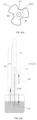
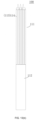
- an introduction needle 100 may include a liquid guiding member 110 and a needle piercing portion 140 disposed at an end of the liquid guiding member 110.
- the needle piercing portion 140 includes a piercing projection 141.
- the piercing projection 141 includes a substrate 1411 and a single needle tooth 1412.
- the needle tooth 1412 is fixedly arranged on a side surface of the substrate 1411.
- a central axis of the needle tooth 1412 is perpendicular to the side surface of the substrate 1411.
- the substrate 1411 may limit a depth that the needle pierces the skin.
- the substrate 1411 presses against the skin to limit the depth that the needle tooth 1412 pierces into the skin.
- the liquid guiding member 110 may be columnar. A side surface of the other side of the substrate 1411 is fixed to an end of the columnar liquid guiding member 110. A central axis of the columnar liquid guiding member 110 is parallel to the central axis of the needle tooth 1412.
- the structure of the introduction needle 100 may be similar to a pen.
- the liquid guiding member 110 may be similar to a barrel of the pen.
- the needle piercing portion 140 may be similar to a tip of the pen.
- the liquid guiding member 110 may pierce the skin in the vertical direction, ensuring that a piercing position may not be shifted, the needle tip may not slip, and a redundant wound may not be generated.
- the liquid guiding member 110 may include a liquid guiding post 111 and a connecting rod 112 connected to the liquid guiding post 111. That is, the liquid guiding member 110 includes two parts, one of the two parts guides ink to flow, and the other one of the two parts is configured for connection and driving.
- the connecting rod 112 is connected to a drive portion. The liquid guiding member 110 reciprocates, driven by the drive portion, along the central axis of the liquid guiding member 110.
- the drive portion may be a motorized rod, and that is, the connecting rod 112 of the liquid guiding member 110 is directly connected to the motorized rod (which may be fixed connection or a non-fixed connection (including abutting connection, hanging connection, and contact connection)).
- the motorized rod directly drives the liquid guiding member 110 to move.
- the drive portion may be an elastic member 170, such as a spring.
- the connecting rod 112 of the liquid guiding member 110 is connected to an end of the spring.
- a case (or a member fixedly connected to the case) is connected to the other end of the spring. Further, an external force is applied to drive the spring to be deformed.
- the liquid guiding member 110 When the liquid guiding member 110 is moving along an axial direction of the case 150 towards a needle outlet end, the liquid guiding member 110 may be reset by a force from the deformed elastic member, such that the liquid guiding member 110 moves reciprocately within the case 150. In still another case, an operator may also hold the connecting rod 112 by hand to directly tattoo.
- the present embodiment provides a piercing projection 141, as shown in FIG. 3(d) .
- the piercing projection 141 may include a substrate 1411 and a needle tooth 1412 arranged on the substrate 1411.
- the substrate 1411 serves as a depth limiting plate to limit a depth that the needle tooth 1412 pierces into the skin.
- the substrate 1411 and the needle tooth 1412 may be configured as a one-piece and integral structure, or configured as separated elements being fixedly connected with each other.
- connection strength and stability of the needle tooth 1412 may be enhanced. Further, safety of the needle tooth 1412 may be improved while the needle tooth 1412 is piercing the skin.
- the one-piece and integral structure may be more suitable for a high frequency piercing process.
- a cross-sectional structure of the skin is noted as h.
- the single needle device 999 of the tattoo tool in the art is connected to the tattoo rod 1004.
- the operator may hold the tattoo rod 1004 by hand to repetitively streak the skin along a direction indicated by an arrow B to color the skin.
- a front end Z of the needle tip 1005 is under the skin and may be subjected to a resistance force F in a direction opposite to the direction B.
- the front end Z of the needle tip 1005 may be bent, as shown at K.
- the front end Z of the needle tip 1005 under the skin may be bent because of a force moment.
- the introduction needle provided by the present invention may limit the depth that the needle tip pierces into the skin, and that is, a maximum moment applied to the needle tip is limited, and the needle tip may be prevented from being bent.
- the cross-sectional structure of the skin is noted as h, and subcutaneous blood vessels are noted as g.
- the operator holds the tattoo rod 1004 by hand to repeatedly prick the skin along the arrow A in an up-down direction to color the skin.
- the needle tip 1005 pierces into the skin to reach position as indicated by c, d, and e, in FIG. 24(a) , and the position c, d, and e refer to different depths under the skin.
- the depths of the positions d and e show that the needle tip has reached locations at which the subcutaneous blood vessels are located.
- the operator may alternatively directly hold the connecting rod 112 to repeatedly prick the skin to color the skin.
- the needle tooth 1412 having a predetermined piercing length pierces into the skin, and the substrate 1411 contacts the skin to form a barrier, such that the piercing depth is limited. As indicated by points 1, 2, and 3 shown in FIG. 24(b) , the piercing depths are controllable and are consistent.
- a height of the needle tooth 1412 is predetermined within a certain range to prevent the subcutaneous blood vessels from being pierced and to prevent the tip from being bent due to an excessive large force moment.
- the needle tooth 1412 of the present invention may be may be a tapered needle tooth.
- a bottom of the tapered needle tooth is connected to the substrate 1411, and a tapered top end of the tapered needle tooth is free end.
- a height range h1412 of the tapered needle tooth is 50 ⁇ m ⁇ h1412 ⁇ 1000 ⁇ m
- a diameter range D1412 of a tapered bottom of the tapered needle teeth is 20 ⁇ m ⁇ D1412 ⁇ 500 ⁇ m, in general, D1412 ⁇ h1412.
- the substrate 1411 is in an arbitrary polygonal shape.
- the needle tooth 1412 is disposed on a side surface of the substrate 1411.
- a minimum edge length of the substrate 1411 is recorded as D1411.
- the pigments may flow to reach the substrate 1411 from the relatively thick liquid guiding post 111 and may further be guided from the substrate to the needle tooth 1412.
- a diameter of a first end face 1111 of the liquid guiding post 111 is D1111.
- D1111 Based on repeated experiments by the inventor, in order to achieve the better effect of guiding the pigments and to have a certain extent of rigidity, 180 ⁇ m ⁇ D1111 ⁇ 1800 ⁇ m, and D1111 > D1411.
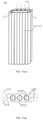
- three channels 115 are defined in the liquid guiding post 111 (CH1, CH2, and CH3 in FIG. 4(c) each represents one of the three channels).
- a length of the liquid guiding post 111 is L111, and L111>D1111.
- a cross section of the piercing projection 141, taken by the substrate 1411 may be arbitrary polygonal, for example, the cross section may be triangular, quadrilateral, pentagonal, or in other regular or irregular polygonal shapes.
- an axial length of the liquid guiding post 111 is at least two times of the length of the shortest edge of the first end face 1111 of the liquid guiding post 111, and the axial length of the liquid guiding post 111 is greater than a length of the longest edge of the first end face 1111.
- the liquid guiding member 110 is arranged with a capillary liquid storage unit 120.
- a channel 115 in the capillary liquid storage unit 120 is defined in an outer wall of the liquid guiding member 110.
- a capillary principle is applied to enable the channel 115 to store the pigments (the pigments and the ink in the present invention both refer to dyes that can color the skin).
- the needle piercing portion 140 of the introduction needle 100 and a bottom of the channel 115 are submerged into the pigments, and the pigments rises along the channel 115 against the gravity.
- the channel 115 serves as a capillary liquid storage unit 120 that can temporarily store the pigments.
- the capillary liquid storage unit may continuously supply ink to the needle tooth of the needle piercing portion.
- the liquid guiding member 110 is dipped into the pigments to intake the pigments, the pigments rises along the capillary liquid storage unit 120 to form a pigment column.
- a height of the pigment column is recorded as H300.
- the piercing projection 141 is fixed to the first end face 1111 of the liquid guiding member 110, and a radius of the channel 115 in the outer wall of the liquid guiding member 110 may be recorded as R115.
- a density of the pigments in the art at room temperature is about 0.7-1.31g/ml, and a surface tension of the pigments at the room temperature is almost equal to a surface tension of water, which is about 72mN/m.
- the ⁇ is an angle between a liquid surface and a wall of the capillary tube.
- the radius of the channel R115 of the liquid storage unit 120 corresponds to the radius of the capillary tube r in the capillary formula.
- a value of the R115 is reduced, a value of the H300 is increased. That is, as the channel of the capillary liquid storage unit 120 is thinner, the height of the pigment column H300 is higher, and more pigments may be carried. Therefore, the needle may not dip the pigments frequently, the tattooing may be performed continuously and efficiently.
- the liquid guiding member 110 of the introduction needle 100 is made of polycarbonate.
- the radius of the channel of the capillary liquid storage unit 120 may be made to have a precision of 0.1 mm, and the height of the pigment column H300 may be more than 100 mm.
- a lowest position W of the introduction needle 100 that is held by the hand is generally not more than 50mm from the needle tip. Therefore, the height H300 of the channel of the capillary liquid storage unit 120 arranged on the introduction needle 100 in the present embodiment is ⁇ 50mm.
- the liquid guiding post 111 is fixed, by adhering, to the substrate 1411 of the piercing projection 141.
- at least one corner V1, V2, and/or an edge M of the substrate 1411 on which the piercing projection 1411 is arranged is aligned with (infinitely approach) an edge of the outer wall of the liquid guiding post 111.
- the substrate 1411 of the piercing projection 141 is disposed at a middle of an end face of the liquid guiding member 110, and a distance from the edge of the outer wall of the liquid guiding member to one corner or one edge of the substrate is not more than 0.18 mm. That is, in an embodiment, the substrate may be disposed at a center of the first end face. However, in order to achieve the better effect of guiding the pigments, a distance from the edge of the outer wall of the liquid guiding member to one corner or one edge of the substrate is not more than 0.18 mm.
- an adhesive seam is defined between the liquid guiding member 110 and the piercing projection 141.
- the introduction needle 100 may be functionally destroyed by separating, by any sharp instrument, the liquid guiding member 110 from the piercing projection 141.
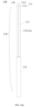
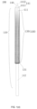
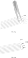
- FIG. 1(a) shows an introduction needle 100, and a depth that the introduction needle 100 pierces into the skin from a single point, may be accurately predefined.
- the introduction needle 100 includes a liquid guiding member 110, a needle piercing portion 140, and a channel 115 defined in an outer wall of the liquid guiding member 110.
- the channel 115 serves as a capillary liquid storage unit 120.
- the liquid guiding post 111 includes three metal filaments ZC1, ZC22, and ZC3 that are cut flat.
- the metal filaments ZC1, ZC22, ZC3 are adjacent to each other and are not fixedly connected to each other.
- a gap between the filaments has a capillary effect and serves as the capillary liquid storage unit.
- the liquid guiding post 111 is fixedly connected to the connecting rod 112.
- the liquid guiding post 111 is welded and fixed to the substrate 1411 of the piercing projection 141.
- the needle tooth 1412 of the present invention is a tower-shaped needle tooth
- the tower-shaped needle tooth includes a columnar tail pin and a tapered top pin integrally formed with an end of the columnar tail pin.
- the other end of the columnar tail pin is fixedly connected to the substrate 1411.
- the edge of the outer wall of the liquid guiding post 111 is aligned with (indefinitely approach) at least one corner J1, J2, J3 of the substrate 1411 and/or with one edge P of the substrate 1411.
- the liquid guiding post 111 is welded and fixed to the piercing projection 141 of the introduction needle 100, in the present embodiment.
- the piercing projection 141 is made of monocrystalline silicon.
- the introduction needle 100 may be functionally destroyed by knocking, by any sharp instrument, off the needle tooth 1412. The destroyed introduction needle may be shown as FIG. 7(b) .
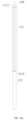
- FIG. 1(d) shows an introduction needle 100, and a depth that the introduction needle 100 pierces into the skin from a single point, may be accurately predefined.
- the introduction needle 100 includes a piercing projection 141, a liquid guiding post 111, and a capillary liquid storage unit 120.
- the piercing projection 141 includes one needle tooth 1412 and a substrate 1411. A depth that the needle tooth 1412 pierces into the skin may be predefined, and the needle tooth 1412 is mounted on the substrate 1411.
- the needle tooth may be tapered.
- the substrate 1411 and the needle tooth 1412 are configured as a one-piece and integral structure. The substrate 1411 limits the depth that the needle tooth 1412 pierces into the skin. In an embodiment, as shown in FIG.
- the liquid guiding post 111 is a strip.
- a fibrous substance may be attached to the outer wall of the liquid guiding post 111.
- a gap in a body of the fibrous substance and a gap between the body of the fibrous substance and the outer wall of the liquid guiding post 111 cooperatively serve as the capillary liquid storage unit 120.
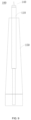
- the liquid guiding post 111 may have a first end face 1111 and a second end face 1112.
- the central axis of the liquid guiding column 111 extends through a center of the first end face 1111 and a center of the second end face 1112.
- the liquid guiding column 111 may be a column in any shape, such as a cylinder, a square column, a cone-like column (or a circular truncated cone), an irregular column, and so on.
- a side surface of the substrate 1411 is fixed to the first end face 1111 of the liquid guiding post 111 (the substrate may be adhered to and fixed to the first end face).
- the connecting rod 112 may be fixedly or detachably connected to the second end face 1112 of the liquid guiding post 111.
- the connecting rod 112 may be a column or in other shapes.
- the connecting rod 112 is substantially configured to connect the liquid guiding post 111 to the drive portion.
- a shape of the liquid guiding post 111 of the present invention may be arbitrary, as long as any one of the following conditions is met.
- a shape of the first end face 1111 is the same as a shape of the second end face 1112, and a size of the first end face 1111 is the same as a size of the second end face 1112.
- the shape of the first end face 1111 is the same as the shape of the second end face 1112, and the size of the first end face 1111 is less than the size of the second end face 1112.
- the shape of the first end face 1111 is different from the shape of the second end face 1112, and the size of the first end face 1111 is less than the size of the second end face 1112.
- the most basic characteristics of the liquid guiding member 110 is that the liquid guiding member 110 is a column.
- the shape of the liquid guiding member 110 is arbitrary.
- the shape of the liquid guiding member 110 may be determined based on the operator's demands.
- the accompanying drawings, which show that the shape is columnar and conical-like, are for illustrating the structure of the liquid guiding member only, and shall not be interpreted as limiting the shape of the shape of the liquid guiding member 110.
- the axial length of the liquid guiding post 111 is greater than a length of the longest edge or a diameter of a cross section of the first end face 1111 of the liquid guiding post 111. That is, the liquid guiding post 111 of the present invention is preferably an elongated column.
- the axial length of the liquid guiding post 111 is at least two times of the length of the shortest edge or the diameter of the first end face 1111 of the liquid guiding post 111, and the axial length of the liquid guiding post 111 is greater than the length of the longest edge or the diameter of the first end face 1111.
- this length-to-diameter ratio is met, the shape of the liquid guiding member 110 is standardized, and the elongated liquid guiding member 110, when being vertically disposed, provides a better liquid guiding and storage effect.
- the tattoo ink 300 (or dye) may be introduced into a superficial layer of the skin through the tattoo tool.
- the tattoo tool in the art may not adsorb, when being submerged into the ink 300, a large amount of ink 300.
- the amount of ink in the tattoo tool does not reach the amount of ink required for one piercing stage. Therefore, a high rate of empty needle during piercing may be caused.
- the liquid guiding member 110 of the introduction needle in the present invention is improved to meet the amount of ink required for one tattoo process.
- the structure of the liquid guiding member 110 will be described in detail below.
- the capillary liquid storage unit 120 is arranged in the liquid guiding post 111. Liquid stored in the capillary liquid storage unit 120 (under the gravitational force or other forces) is guided to flow to the needle piercing portion 140. The needle tooth 1412 pierces into the surface of the skin 200, and at the same time, the liquid is introduced into the surface of the skin 200 along the needle tooth 1412.
- the capillary liquid storage unit 120 may temporarily store the ink 300.
- the liquid guiding member 110 may be submerged in an ink bottle, and the capillary liquid storage unit 120 in the liquid guiding member 110 may adsorb and temporarily store the ink.
- the capillary liquid storage unit 120 is arranged to allow the the liquid guiding member 110 to release the ink gradually, ensuring continuous supply of the ink and reducing a rate of empty needles.
- the introduction needle is required to be break into the skin during the tattoo process. Therefore, the introduction needle that has been used needs to be destroyed to prevent microbial spread caused by secondary usage.
- the introduction needle provided by the present invention has taken this into account. Therefore, as shown in FIGS. 7(a) to 7(b) , the needle tooth 1412 of the introduction needle are destroyed. Alternatively, the needle piercing portion of the introduction needle is directly destroyed, and the remaining liquid guiding post 111 may be further reused.
- the liquid guiding post 111 of the present invention defines a plurality of channels 115.
- the plurality of channels 115 extend along the axial direction of the liquid guiding member 110 and are defined in the outer wall of the liquid guiding post 111 and/or at an interior of the liquid guiding post 111.
- the plurality of channels 115 cooperatively serve as the capillary liquid storage unit 120.
- the capillary liquid storage unit 120 is substantially configured to continuously supplying ink 300 to the tip of the needle tooth 1412.
- At least one of the plurality of channels 115 temporarily stores the liquid, and the liquid in the at least one of the plurality of channels 115 may be guided by the gravitational force to flow to reach the needle tooth 1412 of the needle piercing portion 140.
- the plurality of channels 115 may be integrally defined in the outer wall of the liquid guiding member 110 by etching, cutting, engraving and grinding, or injection molding.
- the plurality of channels 115 are arranged on the outer wall of the liquid guiding post 111.
- the plurality of channels 115 serve as the capillary liquid storage unit 120.
- the plurality of channels 115 in the present embodiment may be objects, such as a needle filament or a needle tube, that are connected to the liquid guiding post 111 and may form a gap.
- the liquid guiding post 111 of the present invention may be formed by a plurality of needle filaments 113 having flat ends and/or a plurality of small posts 114.
- the plurality of needle filaments 113 having the flat ends and the plurality of small posts 114 are arranged adjacent to each other.
- the plurality of said needle filaments 113 having the flat ends are arranged adjacent to each other.
- the plurality of small posts 114 are arranged adjacent to each other.
- a gap between two adjacent needle filaments 113 having the flat ends serves as the channel 115 which serves as the capillary liquid storage unit 120.
- a gap between two adjacent small posts 114 serves as the channel 115 which serves as the capillary liquid storage unit 120.
- a gap between one needle filament 113 having the flat end and one small post 114 serves as the channel 115 which serves as the capillary liquid storage unit 120.
- the needle filament or the small post 114 in the present embodiment may be solid or hollow.
- the capillary may be formed by the gap, which is defined by splicing the needle filaments or the small posts 114.
- the needle filament or the small post 114 may be configured to be hollow to provide an auxiliary capillary.
- the capillary liquid storage unit 120 in the present invention may be arranged by attaching a structure to an outside of the liquid guiding post.
- a liquid storage structure 130 is provided and includes one or more sheets. The sheets are attached to the outer wall of the liquid guiding post 111, and a gap is defined between the outer wall of the liquid guiding post 111 and the sheets. The gap serves as the capillary liquid storage unit 120.
- the capillary liquid storage unit 120 stores liquid temporarily. The liquid is guided to flow to the needle tooth 1412 of the needle piercing portion 140.
- the liquid storage structure 130 is formed by natural or man-made porous sheets.
- the liquid storage structure 130 includes a plurality of filaments.
- the plurality of filaments include fiber filaments 131.
- a gap between the plurality of fiber filaments 131 and a gap between the fiber filaments 131 and the outer wall of the liquid guiding post 111 serve as the capillary liquid storage unit 120.
- the capillary liquid storage unit 120 stores liquid temporarily. The liquid is guided to flow to the needle tooth 1412 of the needle piercing portion 140.
- the fiber filaments 131 may include animal hair, plant fiber filaments 131, chemical fiber filaments, and so on.
- the filaments may further include metal filaments.
- a gap between a plurality of metal filaments and a gap between the metal filaments and the outer wall of the liquid guiding member 110 serve as the capillary storage unit 120.
- the capillary storage unit 120 stores liquid temporarily, and the liquid is guided to flow to the needle tooth 1412 of the needle piercing portion 140.
- a position to which the liquid storage structure 130 is attached and area that the attached liquid storage structure 130 occupies may be determined based on a unit amount of ink stored in the liquid storage structure 130 and a target amount of stored ink of the liquid guiding member 110.
- the number of layers of the liquid storage structure 130 and the area of the liquid storage structure 130 may be customized based on the amount of ink used for tattoo.
- the introduction needle provided in the present invention serving as a tattoo tool, may introduce the tattoo ink 300 into the superficial layer of the skin. Therefore, a liquid guiding path may be formed between the ink 300 adsorbed into the liquid guiding member 110 and the needle tooth 1412 to ensure the ink 300 in the liquid guiding member 110 to flow to the tip of the needle tooth 1412 to be further introduced into the skin. Therefore, in the introduction needle of the present invention, one corner or one edge of at least one substrate 1411 of the piercing projection 141 needs to be disposed near the edge of the outer wall of the liquid guiding member 110. In this way, the needle tooth 1412 arranged on the substrate 1411 may receive the liquid flowing from the liquid guiding member 110.
- the outer edge of the substrate 1411 of the piercing projection 141 has a portion that is substantially aligned with the outer edge of the liquid guiding post 111.
- the aligned portion ensures that the ink in the liquid guiding post 111 may flow to the tip of the needle tooth 1412.
- Similar structures are shown in FIG. 17(a) to FIG. 17(b) or FIG. 18(a) to FIG. 18(b) .
- one corner or one edge of the substrate 1411 of the piercing projection 141 is substantially aligned with the edge of the outer wall of the liquid guiding member 110.
- the substrate 1411 of the piercing projection 141 is disposed at a middle of an end face of the liquid guiding member 110, and the corner or the edge of the substrate 1411 is no more than 0.18 mm away from the edge of the outer wall of the liquid guiding member 110.
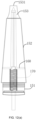
- the introduction needle of the present invention may further be arranged with a case 150.
- the liquid guiding member 110 is arranged inside the case 150.
- the liquid guiding member 110 may move reciprocately inside the case 150 to achieve the piercing operations.
- the case 150 of the present invention may be a tubular cylinder. As shown in FIG. 10 , the case 150 may have a fastening end 151, an intermediate connecting tube 152, and a needle outlet end 153.
- the fastening end 151, the intermediate connecting tube 152, and the needle outlet end 153 are connected to each other sequentially to define a channel for the liquid guiding member 110 to move reciprocactely.
- Each of a central axis of the fastening end 151 and a central axis of the intermediate connecting tube 152 coincides with a central axis of the case 150.
- the fastening end 151 of the present invention is detachably connectable to an external drive member (such that the introduction needle may be replaced easily).
- the needle outlet end 153 defines a needle outlet port 1531.
- the needle tooth 1412 moves reciprocately at a location near the needle outlet port 1531.
- the liquid guiding member 110 and the needle piercing portion 140 disposed at an end of the liquid guiding member 110 are mounted, along the central axis of the case 150, in the intermediate connecting tube 152 of the case 150.
- the needle piercing portion 140 is disposed near the needle outlet end 153.
- the liquid guiding member 110 moves reciprocately in the intermediate connecting tube 152. Further, the liquid guiding member 110 drives the needle tooth 1412 of the needle piercing portion 140 to move out of the needle outlet port 1531 or to move to be retracted into needle outlet port 1531.
- the needle outlet end 153 of the case 150 of the present invention may be tubular.
- the needle outlet port 1531 may have a flat port or a sloped port.
- the needle outlet port 1531 is the flat port
- a gap between the outer wall of the liquid guiding member 110 and an inner wall of the needle outlet end 153 serves as a combined capillary space.
- Liquid may be temporarily stored in the combined capillary space when the needle is intaking the liquid.
- the liquid temporarily stored in the combined capillary may be guided by the gravitational force to flow to the needle piercing portion 140 and may be introduced into the surface layer 200 of the skin while the needle tooth 1412 of the needle piercing portion 140 is piercing into the skin.
- the needle outlet port 1531 is the sloped port
- a gap between the outer wall of the liquid guiding member 110 and an inner wall of the sloped port serves as a combined capillary space.
- Liquid is temporarily stored in the combined capillary space when the needle is intaking the liquid.
- the liquid temporarily stored in the combined capillary space is guided to flow to the needle piercing portion 140 and is introduced into the surface layer of the skin while the needle tooth 1412 of the needle piercing portion 140 is piercing the skin.
- the outer wall of the liquid guiding member 110 may abut against the inner wall of the sloped port.
- the sloped port serves as a limiting plate for the liquid guiding post, allowing the liquid guiding post to be vertically piercing into the skin surface layer.
- an angle may be formed between the central axis of the case and a plane in which the plate of the sloped port is located.
- the sloped port may provide abutting for the liquid guiding member.
- the introduction needle While performing tattoo, the introduction needle is operating at a relatively high frequency. Therefore, while the needle is piercing the skin, the needle may be deviated and skewed, resulting in needle slippage. Therefore, the present invention provides an introduction needle to limit the liquid guiding member 110, assisting the liquid guiding member 110 to pierce into and leave out of the skin in a straight direction, and the piercing may be accurately performed.
- a limiting structure 160 is arranged inside the case 150 of the introduction needle in the present embodiment.
- the limiting structure 160 is disposed inside the intermediate connecting tube 152 of the case 150 and/or on the fastening end 151 of the case 150 and/or on the needle outlet end 153 of the case 150.
- the liquid guiding member 110 may abut against the limiting structure 160.
- the limiting structure 160 limits the liquid guiding member 110 from swinging in a direction along a cross section of the case 150.
- the liquid guiding member 110 drives the needle tooth 1412 of the needle piercing portion 140 to vertically move out of the case 150 to pierce into the skin surface 200. Further, the liquid guiding member 110 drives the needle tooth 1412 of the needle piercing portion 140 to vertically move from the outside of the needle outlet port 1531 to the inside of the case 150.
- the limiting structure 160 of the present invention may be a limiting hole 161.
- the limiting hole 161 may be a through hole.
- a central axis of the through hole may or may not coincide with the central axis of the liquid guiding member 110.
- the central axis of the through hole does not coincide with the central axis of the liquid guiding member 110.
- An inner diameter of the through hole may be adapted to an outer diameter of the liquid guiding member 110.
- a shape and a size of the central through hole may be adapted to a shape and a size of the largest cross section of the liquid guiding member 110.
- a cylindrical liquid guiding member may be adapted with a square through hole.
- a gap between the cylindrical liquid guiding member and the square through hole may provide the capillary effect to store the liquid, ensuring the liquid guiding member 110 to move straight in the central through hole (the limiting structure provides abutting to the liquid guiding member to limit the liquid guiding member from swinging in a lateral direction and to ensure the liquid guiding member to move straight in central through hole).
- the central through hole limits a position of the liquid guiding member 110.
- the central through hole may be circular or irregularly shaped. As shown in FIG. 11(a) , when the through hole is irregularly shaped, the through hole may be suitable for various shapes of liquid guiding members.
- the limiting structure 160 of the present invention may be a limiting tube 162.
- the limiting tube 162 has a channel.
- a central axis of the channel may or may not coincide with the central axis of the liquid guiding member 110.
- An inner diameter of the channel is adapted to the outer diameter of the liquid guiding member 110.
- a shape and a size of the channel are adapted to the shape and the size of the largest cross section of the liquid guiding member 110.
- the adaptation in this case may not refer to the shape and the size of the channel being identical to the shape and the size of the largest cross section of the liquid guiding member, but allows the liquid guiding member to pass through the channel.
- the cylindrical liquid guiding member may be adapted with a square channel. In this case, a gap between the cylindrical liquid guiding member and the square channel may provide the capillary effect to store the liquid, ensuring the liquid guiding member 110 to move straight in the central channel.
- the central channel limits the position of the liquid guiding member 110.
- the limiting structure 160 of the present invention may be a limiting plate 164.
- the limiting plate 164 has a limiting surface. An angle is generated between a plane in which the limiting surface is located and the central axis of the liquid guiding member 110. In one case, the plane in which the limiting surface is located may be parallel to the central axis of the liquid guiding member 110.
- the liquid guiding member 110 is moving reciprocately along the central axis of the case 150, the liquid guiding member 110 abuts against the limiting surface.
- the limiting surface limits the liquid guiding member 110 from swinging in the direction of the cross section of the case 150.
- the limiting plate 164 of the present invention may be disposed at the needle outlet port 1531 of the needle outlet end 153 of the case 150.
- One or more limiting structures 164 may be arranged. When more than one limiting structures 164 are arranged, the more than one limiting structures 164 may be evenly distributed at the needle outlet port 1531 to define a channel, and the needle piercing portion 140 may move straight in and out of the channel.
- the limiting structure 160 of the present invention may be a limiting bracket 163.
- the limiting bracket 163 is disposed at an end of the case 150 (or disposed inside the case).
- the limiting bracket 163 includes one or more sub-brackets. A side of each sub-bracket abuts against the liquid guiding member 110.
- the sub-brackets limit the liquid guiding member 110 from swinging in the direction of the cross section of the case 150.
- the liquid guiding member 110 moves reciprocately along the central axis of the case 150, the liquid guiding member 110 abuts against a side of the sub-bracket. Further, due to abutting against the side of the sub-bracket, the liquid guiding member 110 is guided to move to the needle outlet port 1531 of the case 150.
- the limiting structure 160 in the present embodiment may effectively limit and guide the liquid guiding member 110, ensuring the needle to pierce the skin at desired position accurately and preventing the needle from being skewed or from slipping.
- the introduction needle 100 in the present embodiment may further include an elastic member 170, such as a spring, a silicone member, or a rubber band.
- An end of the elastic member 170 is connected to the case 150, and the other end of the elastic member 170 is connected to the connecting rod of the liquid guiding member 110.
- the elastic member may be connected to the case or the liquid guiding member in various ways, such as connection by abutting, encased connection, or connection by hooks, and so on.
- the case 150 is connected to the motorized rod.
- the elastic member 170 is elastically deformed to drive the liquid guiding member 110 to move back to its initial position.
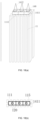
- the present invention further provides an introduction needle 100, and the piercing projection 141 of the introduction needle includes one or more substrates 1411 and one needle tooth 1412 arranged on one substrate 1411. The needle tooth 1412 and the one substrate are arranged in one row.
- the introduction needle having more than one needle teeth are arranged in a row.
- This type of introduction needle may be configured to produce a tattoo having a relatively long linear pattern and a small transition arc.
- the introduction needle having more than one needle teeth in the present embodiment may produce specific patterns more quickly.
- the introduction needle having the single needle tooth may be more advantageous.
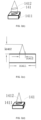
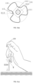
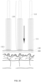
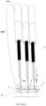
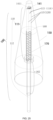
- FIG. 19 is a schematic view showing an in-use state of the introduction needle while intaking the ink.
- the needle piercing portion in the drawings has a plurality of substrates and a plurality of needle teeth.
- the ink in an ink bottle is adsorbed into the capillary liquid storage unit 120 from the end of the liquid guiding member.
- FIG. 20 when the introduction needle is being used to pierce into the skin, each of the plurality of substrates 1411 of the needle piercing portion 140 limits a depth that a corresponding one of the plurality of needle teeth 1412 pierces into the skin.
- the plurality of needle teeth pierce into the skin at the same time. Such an arrangement of the substrates and the needle teeth allows the needle piercing portion to be more suitable for drawing lines.
- the needle piercing portion having a single row of the plurality of needle teeth may also be destroyed simply.
- the present invention further provides a tattoo device.
- the tattoo device includes any one of the above-mentioned introduction needles 100 and an external drive member that drives the liquid guiding member 110 of the introduction needle 100 to move.
- the external drive member includes a manual rod, a motorized rod, and an intelligent arm.
- the introduction needle and tattoo device provided by the present invention has the following advantages:
- the terms “an embodiment”, “some embodiments”, “examples”, “specific examples”, or “some examples” mean that specific features, structures, materials or characteristics described in one embodiment or one example are included in at least one embodiments or examples of the present invention.
- exemplary expressions of the above terms may not be directed to the same embodiment or the same example.
- the specific features, structures, materials, or characteristics described may be combined in any one or more embodiments or examples in a suitable manner.
- any ordinary skilled person in the art may join and combine different embodiments or examples described in the present specification.
Landscapes
- Health & Medical Sciences (AREA)
- Engineering & Computer Science (AREA)
- Dermatology (AREA)
- Medical Informatics (AREA)
- Anesthesiology (AREA)
- Biomedical Technology (AREA)
- Heart & Thoracic Surgery (AREA)
- Hematology (AREA)
- Life Sciences & Earth Sciences (AREA)
- Animal Behavior & Ethology (AREA)
- General Health & Medical Sciences (AREA)
- Public Health (AREA)
- Veterinary Medicine (AREA)
- Virology (AREA)
- Infusion, Injection, And Reservoir Apparatuses (AREA)
- Finger-Pressure Massage (AREA)
Applications Claiming Priority (2)
| Application Number | Priority Date | Filing Date | Title |
|---|---|---|---|
| CN202110402463.0A CN115212444A (zh) | 2021-04-14 | 2021-04-14 | 一种导入针头及纹绣装置 |
| PCT/CN2022/071556 WO2022217990A1 (zh) | 2021-04-14 | 2022-01-12 | 一种导入针头及纹绣装置 |
Publications (2)
| Publication Number | Publication Date |
|---|---|
| EP4321202A1 true EP4321202A1 (de) | 2024-02-14 |
| EP4321202A4 EP4321202A4 (de) | 2024-10-09 |
Family
ID=83605485
Family Applications (1)
| Application Number | Title | Priority Date | Filing Date |
|---|---|---|---|
| EP22787222.3A Pending EP4321202A4 (de) | 2021-04-14 | 2022-01-12 | Einführungsnadel und tätowierungsvorrichtung |
Country Status (4)
| Country | Link |
|---|---|
| US (1) | US11998713B2 (de) |
| EP (1) | EP4321202A4 (de) |
| CN (1) | CN115212444A (de) |
| WO (1) | WO2022217990A1 (de) |
Families Citing this family (2)
| Publication number | Priority date | Publication date | Assignee | Title |
|---|---|---|---|---|
| CN220404632U (zh) * | 2023-03-28 | 2024-01-30 | 王健 | 一种分体式纹绣针刺的连接结构 |
| US12274849B2 (en) * | 2021-04-14 | 2025-04-15 | Tingting XIA | Introduction needle and tattoo device |
Family Cites Families (11)
| Publication number | Priority date | Publication date | Assignee | Title |
|---|---|---|---|---|
| US8251986B2 (en) * | 2000-08-17 | 2012-08-28 | Angiodynamics, Inc. | Method of destroying tissue cells by eletroporation |
| KR100444139B1 (ko) * | 2002-04-10 | 2004-08-11 | 이상호 | 문신기구 |
| IL212262A (en) * | 2011-04-11 | 2014-05-28 | Hawk Medical Technologies Ltd | Skin puncture device for use in a non-surgical tattoo removal method |
| CN202777447U (zh) * | 2012-09-07 | 2013-03-13 | 詹玲莉 | 纹眉机 |
| US20190217072A1 (en) * | 2018-01-18 | 2019-07-18 | Long Xiao | Devices for applying liquid to skin |
| CN207520450U (zh) * | 2017-05-09 | 2018-06-22 | 夏婷婷 | 一种纹绣针 |
| USD888240S1 (en) * | 2018-11-19 | 2020-06-23 | Importla, Llc | Tattoo needle cluster |
| CN209286492U (zh) * | 2018-12-20 | 2019-08-23 | 张立萍 | 新型纹身纹眉纹唇用针 |
| CN209827966U (zh) * | 2019-04-01 | 2019-12-24 | 倪贝贝 | 一种纹绣针头的限位装置 |
| US11291819B2 (en) * | 2019-04-16 | 2022-04-05 | BlinkInk LLC | Customizable tattoo stamp for permanent multicolor tattoo on skin |
| CN211561565U (zh) * | 2019-12-30 | 2020-09-25 | 苏州美沃思医疗科技有限公司 | 一种手持式多功能微针导入仪 |
-
2021
- 2021-04-14 CN CN202110402463.0A patent/CN115212444A/zh active Pending
-
2022
- 2022-01-12 WO PCT/CN2022/071556 patent/WO2022217990A1/zh not_active Ceased
- 2022-01-12 EP EP22787222.3A patent/EP4321202A4/de active Pending
-
2023
- 2023-09-06 US US18/243,091 patent/US11998713B2/en active Active
Also Published As
| Publication number | Publication date |
|---|---|
| EP4321202A4 (de) | 2024-10-09 |
| WO2022217990A1 (zh) | 2022-10-20 |
| CN115212444A (zh) | 2022-10-21 |
| US11998713B2 (en) | 2024-06-04 |
| US20230414914A1 (en) | 2023-12-28 |
Similar Documents
| Publication | Publication Date | Title |
|---|---|---|
| US11998713B2 (en) | Introduction needle and tattoo device | |
| US20220039812A1 (en) | Method of delivering material or stimulus to a biological subject | |
| KR200458906Y1 (ko) | 문신용 니들유닛 및 이를 이용한 문신장치 | |
| US11998714B2 (en) | Tattoo needle and tattoo device | |
| CN204890944U (zh) | 一种超纳微晶美肤枪 | |
| CN215691016U (zh) | 一种导入针头及纹绣装置 | |
| CN216022667U (zh) | 一种一体式单点纹绣针头及纹绣装置 | |
| CN215875950U (zh) | 一种通用纹绣针头及纹绣装置 | |
| CN215875951U (zh) | 一种线雾两用纹绣针头及纹绣装置 | |
| CN215875952U (zh) | 一种一体线式单排纹绣针头及纹绣装置 | |
| US9271805B2 (en) | Isomark needle | |
| US12274849B2 (en) | Introduction needle and tattoo device | |
| CN215691015U (zh) | 一种纹绣针及纹绣装置 | |
| CN215691014U (zh) | 一种纹绣针头及纹绣装置 | |
| CN216022666U (zh) | 一种可持续缓释供墨的多点上色纹绣针头及纹绣装置 | |
| WO2020182665A1 (en) | Jet injection system | |
| US12268834B2 (en) | Introduction needle and tattoo device | |
| CN115212443A (zh) | 一种通用纹绣针头及纹绣装置 | |
| KR102170519B1 (ko) | 피부 시술용 니들 및 이를 이용한 피부 시술 장치 | |
| DE102012009848A1 (de) | Tiefengenaue Kapillarnadel zum repetierenden Einbringen flüssiger Stoffe in die Haut. | |
| JP2007037885A (ja) | 経皮性薬剤配送装置及び経皮性薬剤配送方法並びに経皮性薬剤配送装置用針装置の製造方法 | |
| CN216535444U (zh) | 祛皮赘工具 | |
| KR102631974B1 (ko) | 문신용 니들 장치 | |
| US20260027340A1 (en) | Needle module and mouthpiece for tattoo devices | |
| AT518804B1 (de) | Verfahren und Vorrichtung zum Aufbringen von dekorativen Darstellungen auf einer mehrschichtigen Oberfläche von Kaffee |
Legal Events
| Date | Code | Title | Description |
|---|---|---|---|
| STAA | Information on the status of an ep patent application or granted ep patent |
Free format text: STATUS: THE INTERNATIONAL PUBLICATION HAS BEEN MADE |
|
| PUAI | Public reference made under article 153(3) epc to a published international application that has entered the european phase |
Free format text: ORIGINAL CODE: 0009012 |
|
| STAA | Information on the status of an ep patent application or granted ep patent |
Free format text: STATUS: REQUEST FOR EXAMINATION WAS MADE |
|
| 17P | Request for examination filed |
Effective date: 20231109 |
|
| AK | Designated contracting states |
Kind code of ref document: A1 Designated state(s): AL AT BE BG CH CY CZ DE DK EE ES FI FR GB GR HR HU IE IS IT LI LT LU LV MC MK MT NL NO PL PT RO RS SE SI SK SM TR |
|
| DAV | Request for validation of the european patent (deleted) | ||
| DAX | Request for extension of the european patent (deleted) | ||
| A4 | Supplementary search report drawn up and despatched |
Effective date: 20240910 |
|
| RIC1 | Information provided on ipc code assigned before grant |
Ipc: A61M 37/00 20060101AFI20240904BHEP |