EP4320552B1 - Training von maschinengelernten modulen zur radarbasierten gestenerkennung in einer umgebungsberechnungsumgebung - Google Patents
Training von maschinengelernten modulen zur radarbasierten gestenerkennung in einer umgebungsberechnungsumgebung Download PDFInfo
- Publication number
- EP4320552B1 EP4320552B1 EP22722986.1A EP22722986A EP4320552B1 EP 4320552 B1 EP4320552 B1 EP 4320552B1 EP 22722986 A EP22722986 A EP 22722986A EP 4320552 B1 EP4320552 B1 EP 4320552B1
- Authority
- EP
- European Patent Office
- Prior art keywords
- gesture
- radar
- data
- ambient
- machine
- Prior art date
- Legal status (The legal status is an assumption and is not a legal conclusion. Google has not performed a legal analysis and makes no representation as to the accuracy of the status listed.)
- Active
Links
Images


Classifications
-
- G—PHYSICS
- G06—COMPUTING OR CALCULATING; COUNTING
- G06F—ELECTRIC DIGITAL DATA PROCESSING
- G06F3/00—Input arrangements for transferring data to be processed into a form capable of being handled by the computer; Output arrangements for transferring data from processing unit to output unit, e.g. interface arrangements
- G06F3/01—Input arrangements or combined input and output arrangements for interaction between user and computer
- G06F3/017—Gesture based interaction, e.g. based on a set of recognized hand gestures
-
- G—PHYSICS
- G01—MEASURING; TESTING
- G01S—RADIO DIRECTION-FINDING; RADIO NAVIGATION; DETERMINING DISTANCE OR VELOCITY BY USE OF RADIO WAVES; LOCATING OR PRESENCE-DETECTING BY USE OF THE REFLECTION OR RERADIATION OF RADIO WAVES; ANALOGOUS ARRANGEMENTS USING OTHER WAVES
- G01S13/00—Systems using the reflection or reradiation of radio waves, e.g. radar systems; Analogous systems using reflection or reradiation of waves whose nature or wavelength is irrelevant or unspecified
- G01S13/02—Systems using reflection of radio waves, e.g. primary radar systems; Analogous systems
- G01S13/06—Systems determining position data of a target
- G01S13/08—Systems for measuring distance only
- G01S13/32—Systems for measuring distance only using transmission of continuous waves, whether amplitude-, frequency-, or phase-modulated, or unmodulated
- G01S13/34—Systems for measuring distance only using transmission of continuous waves, whether amplitude-, frequency-, or phase-modulated, or unmodulated using transmission of continuous, frequency-modulated waves while heterodyning the received signal, or a signal derived therefrom, with a locally-generated signal related to the contemporaneously transmitted signal
- G01S13/345—Systems for measuring distance only using transmission of continuous waves, whether amplitude-, frequency-, or phase-modulated, or unmodulated using transmission of continuous, frequency-modulated waves while heterodyning the received signal, or a signal derived therefrom, with a locally-generated signal related to the contemporaneously transmitted signal using triangular modulation
-
- G—PHYSICS
- G01—MEASURING; TESTING
- G01S—RADIO DIRECTION-FINDING; RADIO NAVIGATION; DETERMINING DISTANCE OR VELOCITY BY USE OF RADIO WAVES; LOCATING OR PRESENCE-DETECTING BY USE OF THE REFLECTION OR RERADIATION OF RADIO WAVES; ANALOGOUS ARRANGEMENTS USING OTHER WAVES
- G01S13/00—Systems using the reflection or reradiation of radio waves, e.g. radar systems; Analogous systems using reflection or reradiation of waves whose nature or wavelength is irrelevant or unspecified
- G01S13/02—Systems using reflection of radio waves, e.g. primary radar systems; Analogous systems
- G01S13/50—Systems of measurement based on relative movement of target
- G01S13/58—Velocity or trajectory determination systems; Sense-of-movement determination systems
- G01S13/583—Velocity or trajectory determination systems; Sense-of-movement determination systems using transmission of continuous unmodulated waves, amplitude-, frequency-, or phase-modulated waves and based upon the Doppler effect resulting from movement of targets
- G01S13/584—Velocity or trajectory determination systems; Sense-of-movement determination systems using transmission of continuous unmodulated waves, amplitude-, frequency-, or phase-modulated waves and based upon the Doppler effect resulting from movement of targets adapted for simultaneous range and velocity measurements
-
- G—PHYSICS
- G01—MEASURING; TESTING
- G01S—RADIO DIRECTION-FINDING; RADIO NAVIGATION; DETERMINING DISTANCE OR VELOCITY BY USE OF RADIO WAVES; LOCATING OR PRESENCE-DETECTING BY USE OF THE REFLECTION OR RERADIATION OF RADIO WAVES; ANALOGOUS ARRANGEMENTS USING OTHER WAVES
- G01S7/00—Details of systems according to groups G01S13/00, G01S15/00, G01S17/00
- G01S7/02—Details of systems according to groups G01S13/00, G01S15/00, G01S17/00 of systems according to group G01S13/00
- G01S7/35—Details of non-pulse systems
- G01S7/352—Receivers
- G01S7/358—Receivers using I/Q processing
-
- G—PHYSICS
- G01—MEASURING; TESTING
- G01S—RADIO DIRECTION-FINDING; RADIO NAVIGATION; DETERMINING DISTANCE OR VELOCITY BY USE OF RADIO WAVES; LOCATING OR PRESENCE-DETECTING BY USE OF THE REFLECTION OR RERADIATION OF RADIO WAVES; ANALOGOUS ARRANGEMENTS USING OTHER WAVES
- G01S7/00—Details of systems according to groups G01S13/00, G01S15/00, G01S17/00
- G01S7/02—Details of systems according to groups G01S13/00, G01S15/00, G01S17/00 of systems according to group G01S13/00
- G01S7/41—Details of systems according to groups G01S13/00, G01S15/00, G01S17/00 of systems according to group G01S13/00 using analysis of echo signal for target characterisation; Target signature; Target cross-section
- G01S7/417—Details of systems according to groups G01S13/00, G01S15/00, G01S17/00 of systems according to group G01S13/00 using analysis of echo signal for target characterisation; Target signature; Target cross-section involving the use of neural networks
-
- G—PHYSICS
- G06—COMPUTING OR CALCULATING; COUNTING
- G06N—COMPUTING ARRANGEMENTS BASED ON SPECIFIC COMPUTATIONAL MODELS
- G06N20/00—Machine learning
-
- G—PHYSICS
- G06—COMPUTING OR CALCULATING; COUNTING
- G06N—COMPUTING ARRANGEMENTS BASED ON SPECIFIC COMPUTATIONAL MODELS
- G06N3/00—Computing arrangements based on biological models
- G06N3/02—Neural networks
- G06N3/04—Architecture, e.g. interconnection topology
- G06N3/044—Recurrent networks, e.g. Hopfield networks
- G06N3/0442—Recurrent networks, e.g. Hopfield networks characterised by memory or gating, e.g. long short-term memory [LSTM] or gated recurrent units [GRU]
-
- G—PHYSICS
- G06—COMPUTING OR CALCULATING; COUNTING
- G06N—COMPUTING ARRANGEMENTS BASED ON SPECIFIC COMPUTATIONAL MODELS
- G06N3/00—Computing arrangements based on biological models
- G06N3/02—Neural networks
- G06N3/04—Architecture, e.g. interconnection topology
- G06N3/045—Combinations of networks
-
- G—PHYSICS
- G06—COMPUTING OR CALCULATING; COUNTING
- G06N—COMPUTING ARRANGEMENTS BASED ON SPECIFIC COMPUTATIONAL MODELS
- G06N3/00—Computing arrangements based on biological models
- G06N3/02—Neural networks
- G06N3/04—Architecture, e.g. interconnection topology
- G06N3/0464—Convolutional networks [CNN, ConvNet]
-
- G—PHYSICS
- G06—COMPUTING OR CALCULATING; COUNTING
- G06N—COMPUTING ARRANGEMENTS BASED ON SPECIFIC COMPUTATIONAL MODELS
- G06N3/00—Computing arrangements based on biological models
- G06N3/02—Neural networks
- G06N3/08—Learning methods
- G06N3/082—Learning methods modifying the architecture, e.g. adding, deleting or silencing nodes or connections
-
- G—PHYSICS
- G06—COMPUTING OR CALCULATING; COUNTING
- G06N—COMPUTING ARRANGEMENTS BASED ON SPECIFIC COMPUTATIONAL MODELS
- G06N3/00—Computing arrangements based on biological models
- G06N3/02—Neural networks
- G06N3/08—Learning methods
- G06N3/09—Supervised learning
-
- G—PHYSICS
- G06—COMPUTING OR CALCULATING; COUNTING
- G06N—COMPUTING ARRANGEMENTS BASED ON SPECIFIC COMPUTATIONAL MODELS
- G06N3/00—Computing arrangements based on biological models
- G06N3/02—Neural networks
- G06N3/08—Learning methods
- G06N3/0985—Hyperparameter optimisation; Meta-learning; Learning-to-learn
-
- G—PHYSICS
- G06—COMPUTING OR CALCULATING; COUNTING
- G06N—COMPUTING ARRANGEMENTS BASED ON SPECIFIC COMPUTATIONAL MODELS
- G06N5/00—Computing arrangements using knowledge-based models
- G06N5/01—Dynamic search techniques; Heuristics; Dynamic trees; Branch-and-bound
-
- H—ELECTRICITY
- H04—ELECTRIC COMMUNICATION TECHNIQUE
- H04L—TRANSMISSION OF DIGITAL INFORMATION, e.g. TELEGRAPHIC COMMUNICATION
- H04L27/00—Modulated-carrier systems
- H04L27/10—Frequency-modulated carrier systems, i.e. using frequency-shift keying
- H04L27/103—Chirp modulation
-
- G—PHYSICS
- G06—COMPUTING OR CALCULATING; COUNTING
- G06N—COMPUTING ARRANGEMENTS BASED ON SPECIFIC COMPUTATIONAL MODELS
- G06N3/00—Computing arrangements based on biological models
- G06N3/02—Neural networks
- G06N3/04—Architecture, e.g. interconnection topology
- G06N3/044—Recurrent networks, e.g. Hopfield networks
Definitions
- a user may use one or more smart devices to get daily weather and traffic information, control a temperature of a home, answer a doorbell, turn on or off a light, and/or play background music. Interacting with some smart devices, however, can be cumbersome and inefficient.
- a smart device for instance, can have a physical user interface that may require a user to navigate through one or more prompts by physically touching the smart device. In this case, the user has to devote attention away from other primary tasks to interact with the smart device, which can be inconvenient and disruptive.
- Gesture recognition using machine learning is e.g. known from US 2019/383903 A1 or EP 5 651 055 A1 .
- a smart device with a radar system can support ambient computing by providing an eye-free interaction and less cognitively demanding gesture-based user interface.
- the radar system can be designed to address a variety of challenges associated with ambient computing, including power consumption, environmental variations, background noise, size, and user privacy.
- the radar system uses an ambient-computing machine-learned module to quickly recognize gestures performed by a user up to at least two meters away.
- the training of the ambient-computing machine-learned module involves, in part, a two-phase evaluation process.
- the two-phase evaluation process includes a first phase, which performs a segmented classification task using pre-segmented data.
- a second phase performs an unsegmented recognition task using unsegmented or continuous time-series data and a gesture debouncer.
- the unsegmented recognition task can be significantly more challenging than the segmented classification task as it is unknown when the gestures occur within the continuous time-series data.
- the ambient-computing machine-learned module can be trained to filter background noise and have a sufficiently low false positive rate to enhance the user experience.
- a claimed solution is specified by a method according to claim 1 and by a system according to claim 15.
- Dependent claims specify embodiments thereof. Aspects described below include a method for training a machine-learned module to perform ambient computing.
- the method includes evaluating a machine-learned module using a two-phase evaluation process.
- the evaluating comprises performing, using pre-segmented data, a segmented classification task using the machine-learned module to evaluate an error associated with classification of multiple gestures.
- the pre-segmented data comprising complex radar data having multiple gesture segments.
- Each gesture segment of the multiple gesture segments comprises a gesture motion. Centers of gesture motions across the multiple gesture segments have a same relative timing alignment within each gesture segment.
- the method also includes performing, using continuous time-series data, an unsegmented recognition task using the machine-learned module to evaluate a false positive rate.
- the continuous time-series data comprises other complex radar data.
- the method additionally includes adjusting one or more elements of the machine-learned module to reduce the error and the false positive rate.
- aspects described below also include a system comprising a radar system and a processor.
- the processor configured to process complex radar data generated by the radar system according to a machine-learned module having been trained according to any one of the described methods.
- aspects described below include a computer-readable storage medium comprising computer-executable instructions that, responsive to execution by a processor, cause a system to perform any one of the described methods.
- aspects described below also include a smart device comprising a radar system and a processor.
- the processor configured to process complex radar data generated by the radar system according to a machine-learned module having been trained according to any one of the described methods.
- aspects described below also include a system with means for training a machine-learned module of a radar system to perform ambient computing.
- a user may use one or more smart devices to get daily weather and traffic information, control a temperature of a home, answer a doorbell, turn on or off a light, and/or play background music. Interacting with some smart devices, however, can be cumbersome and inefficient.
- a smart device for instance, can have a physical user interface that may require a user to navigate through one or more prompts by physically touching the smart device. In this case, the user has to devote attention away from other primary tasks to interact with the smart device, which can be inconvenient and disruptive.
- some smart devices support ambient computing, which enables a user to interact with the smart device in a non-physical and less cognitively demanding way compared to other interfaces that require physical touch and/or the user's visual attention.
- ambient computing the smart device seamlessly exists in the surrounding environment and provides the user access to information and services while the user performs a primary task, such as cooking, cleaning, driving, talking with people, or reading a book.
- a second challenge is the various environments in which the smart device may perform ambient computing.
- natural changes occur in a given environment based on the progression of time (e.g., from day to night, or from summer to winter). These natural changes can lead to temperature fluctuations and/or changes in lighting conditions. As such, it is desirable for the smart device to be able to perform ambient computing across such environmental variations.
- a third challenge involves background noise.
- Smart devices that perform ambient computing can experience a larger quantity of background noise as they operate in the perpetual "on state" compared to other devices that enable user interactions in response to a touch-based input.
- the background noise can include background conversations.
- this can include other movements that are associated with everyday tasks.
- a fourth challenge is size. It is desirable for the smart device to have a relatively small footprint. This enables the smart device to be embedded within other objects or occupy less space on a counter or wall.
- a fifth challenge is user privacy. As smart devices may be used in personal spaces (e.g., including bedrooms, living rooms, or workplaces), it is desirable to incorporate ambient computing in a way that protects the user's privacy.
- the radar system can be integrated within power-constrained and space-constrained smart devices.
- the radar system consumes twenty milliwatts of power or less and has a footprint of four millimeters by six millimeters.
- the radar system can also be readily housed behind materials that do not substantially affect radio-frequency signal propagation, such as plastic, glass, or other non-metallic materials.
- the radar system is less susceptible to temperature or lighting variations compared to an infrared sensor or a camera.
- the radar sensor does not produce a distinguishable representation of a user's spatial structure or voice. In this way, the radar sensor can provide better privacy protection compared to other image-based sensors.
- the radar system uses an ambient-computing machine-learned module, which is designed to operate with limited power and limited computational resources.
- the ambient-computing machine-learned module enables the radar system to quickly recognize gestures performed by a user at distance of at least two meters away. This allows the user flexibility to interact with the smart device while performing other tasks at farther distances away from the smart device.
- the training of the ambient-computing machine-learned module involves, in part, a two-phase evaluation process.
- the two-phase evaluation process includes a first phase, which performs a segmented classification task using pre-segmented data.
- a second phase performs an unsegmented recognition task using unsegmented or continuous time-series data and a gesture debouncer.
- the unsegmented recognition task can be significantly more challenging than the segmented classification task as it is unknown when the gestures occur within the continuous time-series data.
- the ambient-computing machine-learned module can be trained to filter background noise and have a sufficiently low false positive rate to enhance the user experience.
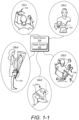
- FIG. 1-1 is an illustration of example environments 100-1 to 100-5 in which techniques using, and an apparatus including, ambient computing using a radar system may be embodied.
- a smart device 104 includes a radar system 102 capable of performing ambient computing.
- the smart device 104 is shown to be a smartphone in environments 100-1 to 100-5, the smart device 104 can generally be implemented as any type of device or object, as further described with respect to FIG. 2 .
- a user performs different types of gestures, which are detected by the radar system 102.
- the user performs a gesture using an appendage or body part.
- the user can also perform a gesture using a stylus, a hand-held object, a ring, or any type of material that can reflect radar signals.
- gestures can be associated with a particular direction used for navigating visual or audible content presented by the smart device 104. These gestures may be performed along a horizontal plane that is substantially parallel to the smart device 104 (e.g., substantially parallel to a display of the smart device 104). For instance, a user can perform a first swipe gesture that travels from a left side of the smart device 104 to a right side of the smart device 104 (e.g., a right swipe) to play a next song in a queue or skip forwards within a song.
- a first swipe gesture that travels from a left side of the smart device 104 to a right side of the smart device 104 (e.g., a right swipe) to play a next song in a queue or skip forwards within a song.
- the smart device can support ambient computing by providing shortcuts to everyday tasks.
- Example shortcuts include managing interruptions from alarm clocks, timers, or smoke detectors.
- Other shortcuts include accelerating interactions with a voice-controlled smart device. This type of shortcut can activate voice recognition in the smart device without using key words to wake-up the smart device.
- a user may prefer to use gesture-based shortcuts instead of voice-activated shortcuts, particularly in situations in which they are engaged in conversation or in environments where it may be inappropriate to speak, such as in a classroom or in a quiet section of a library.
- ambient computing using the radar system can enable the user to accept or decline a change in global navigation satellite system (GNSS) route.
- GNSS global navigation satellite system
- Ambient computing also has applications in public spaces to control everyday objects.
- the radar system 102 can recognize gestures that control features of a building. These gestures can enable people to open automatic doors, select a floor within an elevator, and raise or lower blinds in an office room.
- the radar system 102 can recognize gestures to operate faucets, flush a toilet, or a drinking fountain.
- the radar system 102 recognizes different types of swipe gestures, which are further described with respect to FIG. 1-2 .
- the radar system can also recognize a tap gesture, which is further described with respect to FIG. 1-3 .
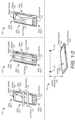
- FIG. 1-2 illustrates example types of swipe gestures associated with ambient computing.
- a swipe gesture represents a sweeping motion that traverses at least two sides of the smart device 104.
- the swipe gesture can resemble a motion made to brush crumbs off a table.
- the user can perform the swipe gesture using a hand oriented with a palm facing towards the smart device 104 (e.g., with the hand positioned parallel to the smart device 104).
- the user can perform the swipe gesture using a hand with the palm facing towards or away from the direction of motion (e.g., with the hand positioned perpendicular to the smart device 104).
- the swipe gesture may be associated with a timing requirement. For example, to be considered a swipe gesture, the user is to sweep an object across two opposite points on the smart device 104 within approximately 0.5 seconds.
- the third side 108-3 of the smart device 104 corresponds to a top side of the smart device 104
- a fourth side 108-4 of the smart device 104 corresponds to a bottom of the smart device 104 (e.g., a side positioned proximate to the ground).
- arrows depict a direction of a right swipe 112 (e.g., a right-swipe gesture) and a direction of a left swipe 114 (e.g., a left-swipe gesture) relative to the smart device 104.
- the user moves an object (e.g., an appendage or a stylus) from the first side 108-1 of the smart device 104 to the second side 108-2 of the smart device 104.
- the left swipe 114 the user moves an object from the second side 108-2 of the smart device 104 to the first side 108-1 of the smart device 104.
- the right swipe 112 and the left swipe 114 traverse a path that is substantially parallel to the third and fourth sides 108-3 and 108-4 and substantially perpendicular to the first and second sides 108-1 and 108-2.
- arrows depict a direction of an up swipe 118 (e.g., an up-swipe gesture) and a direction of a down swipe 120 (e.g., a down-swipe gesture) relative to the smart device 104.
- an up swipe 118 e.g., an up-swipe gesture
- a down swipe 120 e.g., a down-swipe gesture
- the up swipe 118 and the down swipe 120 traverse a path that is substantially parallel to the first and second sides 108-1 and 108-2 and substantially perpendicular to the third and fourth sides 108-3 and 108-4.
- an arrow depicts a direction of an example omni swipe (e.g., an omni-swipe gesture) relative to the smart device 104 using an arrow.
- the omni swipe 124 represents a swipe that is not necessarily parallel or perpendicular to a given side.
- the omni swipe 124 represents any type of swipe motion, including the directional swipes mentioned above (e.g., the right swipe 112, the left swipe 114, the up swipe 118, and the down swipe 120).
- the omni swipe 124 is a diagonal swipe that traverses from a point where the sides 108-1 and 108-3 touch to another point where the sides 108-2 and 108-4 touch.
- Other types of diagonal motions are also possible, such as a diagonal swipe from a point where the sides 108-1 and 108-4 touch to another point where the sides 108-2 and 108-3 touch.
- the various swipe gestures can be defined from a device-centric perspective.
- a right swipe 112 generally travels from a left side of the smart device 104 to a right side of the smart device 104, regardless of the smart device 104's orientation.
- the smart device 104 is positioned in a landscape orientation with the display 106 facing the user and the third side 108-3 with the radar system 102 positioned on a right side of the smart device 104.
- the first side 108-1 represents the top side of the smart device 104
- the second side 108-2 represents the bottom side of the smart device 104.
- the third side 108-3 represents a right side of the smart device 104
- the fourth side 108-4 represents a left side of the smart device 104.
- the user performs the right swipe 112 or the left swipe 114 by moving an object across the third side 108-3 and the fourth side 108-4.
- the user moves an object across the first side 108-1 and the second side 108-2.
- a vertical distance 128 between the object performing any of the swipe gestures 112, 114, 118, 120, and 124 and the front surface of the smart device 104 is shown to remain relatively unchanged throughout the gesture.
- a start position 130 of a swipe gesture can be at approximately a same vertical distance 128 from the smart device 104 as an end position 132 of the swipe gesture.
- the term "approximately” can mean that the distance of the start position 130 can be within +/-10% of the distance of the end position 132 or less (e.g., within +/- 5%, +/- 3%, or +/-2% of the end position 132).
- the swipe gesture involves a motion that traverses a path that is substantially parallel to a surface of the smart device 104 (e.g., substantially parallel to the surface of the display 106).
- the swipe gesture may be associated with a particular range of vertical distances 128 from the smart device 104.
- a gesture can be considered a swipe gesture if the gesture is performed at a vertical distance 128 that is between approximately 3 and 20 centimeters from the smart device 104.
- the term "approximately” can mean that the distance of can be within +/-10% of a specified value or less (e.g., within +/- 5%, +/- 3%, or +/-2% of a specified value).
- the start position 130 and the end position 132 of other swipe gestures can be positioned further away from the smart device 104, especially in situations in which the user performs the swipe gestures at a horizontal distance from the smart device 104.
- the user can perform the swipe gesture more than 0.3 meters away from the smart device 104.
- FIG. 1-3 illustrates an example tap gesture associated with ambient computing.
- a tap gesture is a "bounce-like" motion that first moves towards the smart device 104 and then moves away from the smart device 104. This motion is substantially perpendicular to a surface of the smart device 104 (e.g., substantially perpendicular to a surface of the display 106).
- the user can perform the tap gesture using a hand with a palm that faces towards the smart device 104 (e.g., with the hand positioned parallel to the smart device 104).
- FIG. 1-3 depicts a motion of the tap gesture over time, with time progressing from left to right.
- the user positions an object (e.g., an appendage or a stylus) at a start position 136, which is at a first distance 138 from the smart device 104.
- the user moves the object from the start position 136 to a middle position 140.
- the middle position 140 is at a second distance 142 from the smart device 104.
- the second distance 142 is less than the first distance 138.
- the user moves the object from the middle position 140 to the end position 146, which is at a third distance 148 from the smart device 104.
- the third distance 148 is greater than the second distance 142.
- the third distance 148 can be similar to or different than the first distance 138.
- the smart device 104 and the radar system 102 are further described with respect to FIG. 2 .
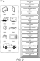
- FIG. 2 illustrates the radar system 102 as part of the smart device 104.
- the smart device 104 is illustrated with various non-limiting example devices including a desktop computer 104-1, a tablet 104-2, a laptop 104 3, a television 104-4, a computing watch 104-5, computing glasses 104-6, a gaming system 104-7, a microwave 104-8, and a vehicle 104-9.
- Other devices may also be used, such as a home service device, a smart speaker, a smart thermostat, a security camera, a baby monitor, a Wi-Fi TM router, a drone, a trackpad, a drawing pad, a netbook, an e-reader, a home automation and control system, a wall display, and another home appliance.
- the smart device 104 can be wearable, non-wearable but mobile, or relatively immobile (e.g., desktops and appliances).
- the radar system 102 can be used as a stand-alone radar system or used with, or embedded within, many different smart devices 104 or peripherals, such as in control panels that control home appliances and systems, in automobiles to control internal functions (e.g., volume, cruise control, or even driving of the car), or as an attachment to a laptop computer to control computing applications on the laptop.
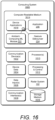
- the smart device 104 includes one or more computer processors 202 and at least one computer-readable medium 204, which includes memory media and storage media. Applications and/or an operating system (not shown) embodied as computer-readable instructions on the computer-readable medium 204 can be executed by the computer processor 202 to provide some of the functionalities described herein.
- the computer-readable medium 204 also includes an application 206, which uses an ambient computing event (e.g., a gesture input) detected by the radar system 102 to perform an action associated with gesture-based touch-free control.
- the radar system 102 can also provide radar data to support presence-based touch-free control, collision avoidance for autonomous driving, health monitoring, fitness tracking, spatial mapping, human activity recognition, and so forth.
- the smart device 104 can also include a network interface 208 for communicating data over wired, wireless, or optical networks.
- the network interface 208 may communicate data over a local-area-network (LAN), a wireless local-area-network (WLAN), a personal-area-network (PAN), a wire-area-network (WAN), an intranet, the Internet, a peer-to-peer network, point-to-point network, a mesh network, and the like.
- the smart device 104 may also include the display 106.
- the radar system 102 includes a communication interface 210 to transmit radar data to a remote device, though this need not be used when the radar system 102 is integrated within the smart device 104.
- the radar data can include the ambient computing event and can optionally include other types of data, such as data associated with presence detection, collision avoidance, health monitoring, fitness tracking, spatial mapping, or human activity recognition.
- the radar data provided by the communication interface 210 is in a format usable by the application 206.
- the radar system 102 also includes at least one antenna array 212 and at least one transceiver 214 to transmit and receive radar signals.
- the antenna array 212 includes at least one transmit antenna element and at least two receive antenna elements. In some situations, the antenna array 212 includes multiple transmit antenna elements and/or multiple receive antenna elements. With multiple transmit antenna elements and multiple receive antenna elements, the radar system 102 can implement a multiple-input multiple-output (MIMO) radar capable of transmitting multiple distinct waveforms at a given time (e.g., a different waveform per transmit antenna element).
- MIMO multiple-input multiple-output
- the antenna elements can be circularly polarized, horizontally polarized, vertically polarized, or a combination thereof.
- the multiple receive antenna elements of the antenna array 212 can be positioned in a one-dimensional shape (e.g., a line) or a two-dimensional shape (e.g., a rectangular arrangement, a triangular arrangement, or an "L" shape arrangement) for implementations that include three or more receive antenna elements.
- the one-dimensional shape enables the radar system 102 to measure one angular dimension (e.g., an azimuth or an elevation) while the two-dimensional shape enables the radar system 102 to measure two angular dimensions (e.g., to determine both an azimuth angle and an elevation angle of the object).
- An element spacing associated with the receive antenna elements can be less than, greater than, or equal to half a center wavelength of the radar signal.
- the transceiver 214 includes circuitry and logic for transmitting and receiving radar signals via the antenna array 212.
- Components of the transceiver 214 can include amplifiers, phase shifters, mixers, switches, analog-to-digital converters, or filters for conditioning the radar signals.
- the transceiver 214 also includes logic to perform in phase/quadrature (I/Q) operations, such as modulation or demodulation.
- I/Q phase/quadrature
- modulation or demodulation can be used, including linear frequency modulations, triangular frequency modulations, stepped frequency modulations, or phase modulations.
- the transceiver 214 can produce radar signals having a relatively constant frequency or a single tone.
- the transceiver 214 can be configured to support continuous-wave or pulsed radar operations.
- a frequency spectrum (e.g., range of frequencies) that the transceiver 214 uses to generate the radar signals can encompass frequencies between 1 and 400 gigahertz (GHz), between 4 and 100 GHz, between 1 and 24 GHz, between 24 GHz and 70 GHz, between 2 and 4 GHz, between 57 and 64 GHz, or at approximately 2.4 GHz.
- the frequency spectrum can be divided into multiple sub-spectrums that have similar or different bandwidths.
- the bandwidths can be on the order of 500 megahertz (MHz), 1 GHz, 2 GHz, 4 GHz, 6 GHz, and so forth. In some cases, the bandwidths are approximately 20% or more of a center frequency to implement an ultrawideband (UWB) radar.
- UWB ultrawideband
- Different frequency sub-spectrums may include, for example, frequencies between approximately 57 and 59 GHz, 59 and 61 GHz, or 61 and 63 GHz.
- the example frequency sub-spectrums described above are contiguous, other frequency sub-spectrums may not be contiguous.
- multiple frequency sub-spectrums (contiguous or not) that have a same bandwidth may be used by the transceiver 214 to generate multiple radar signals, which are transmitted simultaneously or separated in time.
- multiple contiguous frequency sub-spectrums may be used to transmit a single radar signal, thereby enabling the radar signal to have a wide bandwidth.
- the radar system 102 also includes one or more system processors 216 and at least one system medium 218 (e.g., one or more computer-readable storage media).
- the system medium 218 optionally includes a hardware abstraction module 220.
- the radar system 102's system medium 218 includes an ambient-computing machine-learned module 222 and a gesture debouncer 224.
- the hardware abstraction module 220, the ambient-computing machine-learned module 222, and the gesture debouncer 224 can be implemented using hardware, software, firmware, or a combination thereof.
- the system processor 216 implements the hardware-abstraction module 220, the ambient-computing machine-learned module 222, and the gesture debouncer 224.
- the hardware-abstraction module 220, the ambient-computing machine-learned module 222, and the gesture debouncer enable the system processor 216 to process responses from the receive antenna elements in the antenna array 212 to recognize a gesture performed by the user in the context of ambient computing.
- the hardware-abstraction module 220, the ambient-computing machine-learned module 222, and/or the gesture debouncer 224 are included within the computer-readable medium 204 and implemented by the computer processor 202. This enables the radar system 102 to provide the smart device 104 raw data via the communication interface 210 such that the computer processor 202 can process the raw data for the application 206.
- the hardware-abstraction module 220 transforms raw data provided by the transceiver 214 into hardware-agnostic data, which can be processed by the ambient-computing machine-learned module 222.
- the hardware-abstraction module 220 conforms complex data from a variety of different types of radar signals to an expected input of the ambient-computing machine-learned module 222. This enables the ambient-computing machine-learned module 222 to process different types of radar signals received by the radar system 102, including those that utilize different modulations schemes for frequency-modulated continuous-wave radar, phase-modulated spread spectrum radar, or impulse radar.
- the hardware-abstraction module 220 can also normalize complex data from radar signals with different center frequencies, bandwidths, transmit power levels, or pulsewidths.
- the hardware-abstraction module 220 conforms complex data generated using different hardware architectures.
- Different hardware architectures can include different antenna arrays 212 positioned on different surfaces of the smart device 104 or different sets of antenna elements within an antenna array 212.
- the ambient-computing machine-learned module 222 can process complex data generated by different sets of antenna elements with different gains, different sets of antenna elements of various quantities, or different sets of antenna elements with different antenna element spacings.
- the ambient-computing machine-learned module 222 can operate in radar systems 102 with different limitations that affect the available radar modulation schemes, transmission parameters, or types of hardware architectures.
- the hardware-abstraction module 220 is further described with respect to FIGs. 6-1 and 6-2 .
- Some types of machine-learned modules are designed and trained to recognize gestures within a particular or segmented time interval, such as a time interval initiated by a touch event or a time interval corresponding to a display being in an active state.
- the ambient-computing machine-learned module is designed and trained to recognize gestures across time in a continuous and unsegmented manner.
- the gesture debouncer 224 determines whether or not the user performed a gesture based on the likelihoods (or probabilities) provided by the ambient-computing machine-learned module 222.
- the gesture debouncer 224 is further described with respect to FIGs. 7-1 and 7-2 .
- the radar system 102 is further described with respect to FIG. 3-1 .
- FIG. 3-1 illustrates an example operation of the radar system 102.
- the radar system 102 is implemented as a frequency-modulated continuous-wave radar.
- other types of radar architectures can be implemented, as described above with respect to FIG. 2 .
- an object 302 is located at a particular slant range 304 from the radar system 102 and is manipulated by a user to perform a gesture.
- the object 302 can be an appendage of the user (e.g., a hand, a finger, or an arm), an item that is worn by the user, or an item that is held by the user (e.g., a stylus).
- the radar system 102 transmits a radar transmit signal 306.
- the radar system 102 can transmit the radar transmit signal 306 using a substantially broad radiation pattern.
- a main lobe of the radiation pattern can have a beamwidth that is approximately 90 degrees or greater (e.g., approximately 110, 130, or 150 degrees).
- This broad radiation pattern enables the user more flexibility in where they perform a gesture for ambient computing.
- a center frequency of the radar transmit signal 306 can be approximately 60 GHz
- a bandwidth of the radar transmit signal 306 can be between approximately 4 and 6 GHz (e.g., approximately 4.5 or 5.5 GHz).
- the term "approximately" can mean that the bandwidths of can be within +/-10% of a specified value or less (e.g., within +/- 5%, +/- 3%, or +/-2% of a specified value).
- At least a portion of the radar transmit signal 306 is reflected by the object 302. This reflected portion represents a radar receive signal 308.
- the radar system 102 receives the radar receive signal 308 and processes the radar receive signal 308 to extract data for gesture recognition. As depicted, an amplitude of the radar receive signal 308 is smaller than an amplitude of the radar transmit signal 306 due to losses incurred during propagation and reflection.
- the radar transmit signal 306 includes a sequence of chirps 310-1 to 310-N, where N represents a positive integer greater than one.
- the radar system 102 can transmit the chirps 310-1 to 310-N in a continuous burst or transmit the chirps 310-1 to 310-N as time-separated pulses, as further described with respect to FIG. 3-2 .
- a duration of each chirp 310-1 to 310-N can be on the order of tens or thousands of microseconds (e.g., between approximately 30 microseconds ( ⁇ s) and 5 milliseconds (ms)), for instance.
- An example pulse repetition frequency (PRF) of the radar system 102 can be greater than 1500 Hz, such as approximately 2000 Hz or 3000 Hz.
- the term “approximately” can mean that the pulse repetition frequencies of can be within +/-10% of a specified value or less (e.g., within +/- 5%, +/- 3%, or +/-2% of a specified value).
- the radar system 102 employs a two-slope cycle (e.g., triangular frequency modulation) to linearly increase and linearly decrease the frequencies of the chirps 310-1 to 310-N over time.
- the two-slope cycle enables the radar system 102 to measure the Doppler frequency shift caused by motion of the object 302.
- transmission characteristics of the chirps 310-1 to 310-N e.g., bandwidth, center frequency, duration, and transmit power
- chirp generally refers to a segment or portion of the radar signal.
- the “chirp” represents individual pulses of a pulsed radar signal.
- the “chirp” represents segments of a continuous-wave radar signal.
- the radar receive signal 308 represents a delayed version of the radar transmit signal 306.
- the amount of delay is proportional to the slant range 304 (e.g., distance) from the antenna array 212 of the radar system 102 to the object 302.
- this delay represents a summation of a time it takes for the radar transmit signal 306 to propagate from the radar system 102 to the object 302 and a time it takes for the radar receive signal 308 to propagate from the object 302 to the radar system 102. If the object 302 is moving, the radar receive signal 308 is shifted in frequency relative to the radar transmit signal 306 due to the Doppler effect.
- a difference in frequency between the radar transmit signal 306 and the radar receive signal 308 can be referred to as a beat frequency 312.
- a value of the beat frequency is based on the slant range 304 and the Doppler frequency.
- the radar receive signal 308 is composed of one or more of the chirps 310-1 to 310-N.
- the multiple chirps 310-1 to 310-N enable the radar system 102 to make multiple observations of the object 302 over a predetermined time period.
- a radar framing structure determines a timing of the chirps 310-1 to 310-N, as further described with respect to FIG. 3-2 .
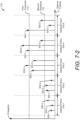
- FIG. 3-2 illustrates an example radar framing structure 314 for ambient computing.
- the radar framing structure 314 includes three different types of frames.
- the radar framing structure 314 includes a sequence of gesture frames 316 (or main frames), which can be in an active state or an inactive state.
- the active state consumes a larger amount of power relative to the inactive state.
- the radar framing structure 314 includes a sequence of feature frames 318, which can similarly be in the active state or the inactive state.
- Different types of feature frames 318 include a pulse-mode feature frame 320 (shown at the bottom-left of FIG.
- the radar framing structure 314 includes a sequence of radar frames (RF) 324, which can also be in the active state or the inactive state.
- RF radar frames
- the radar system 102 transmits and receives a radar signal during an active radar frame 324.
- the radar frames 324 are individually analyzed for basic radar operations, such as search and track, clutter map generation, user location determination, and so forth. Radar data collected during each active radar frame 324 can be saved to a buffer after completion of the radar frame 324 or provided directly to the system processor 216 of FIG. 2 .
- the radar system 102 analyzes the radar data across multiple radar frames 324 (e.g., across a group of radar frames 324 associated with an active feature frame 318) to identify a particular feature.
- Example types of features include one or more stationary objects within the external environment, material characteristics of these one or more objects (e.g., reflective properties), physical characteristics (e.g., size) of these one or more objects.
- the radar system 102 analyzes the radar data associated with multiple active feature frames 318.
- a duration of the gesture frame 316 may be on the order of milliseconds or seconds (e.g., between approximately 10 milliseconds (ms) and 10 seconds (s)).
- the radar system 102 is inactive, as shown by inactive gesture frames 316-3 and 316-4.
- a duration of the inactive gesture frames 316-3 and 316-4 is characterized by a deep sleep time 326, which may be on the order of tens of milliseconds or more (e.g., greater than 50 ms).
- the radar system 102 turns off all of the active components (e.g., an amplifier, an active filter, a voltage-controlled oscillator (VCO), a voltage-controlled buffer, a multiplexer, an analog-to-digital converter, a phase-lock loop (PLL) or a crystal oscillator) within the transceiver 214 to conserve power during the deep sleep time 326.
- the active components e.g., an amplifier, an active filter, a voltage-controlled oscillator (VCO), a voltage-controlled buffer, a multiplexer, an analog-to-digital converter, a phase-lock loop (PLL) or a crystal oscillator
- each gesture frame 316 includes K feature frames 318, where K is a positive integer. If the gesture frame 316 is in the inactive state, all of the feature frames 318 associated with that gesture frame 316 are also in the inactive state. In contrast, an active gesture frame 316 includes J active feature frames 318 and K-J inactive feature frames 318, where J is a positive integer that is less than or equal to K.
- a quantity of feature frames 318 can be adjusted based on a complexity of the environment or a complexity of a gesture. For example, a gesture frame 316 can include a few to a hundred feature frames 316 or more (e.g., K may equal 2, 10, 30, 60, or 100).
- a duration of each feature frame 318 may be on the order of milliseconds (e.g., between approximately 1 ms and 50 ms). In example implementations, the duration of each feature frame 318 is between approximately 30 ms and 50 ms.
- the active feature frames 318-1 to 318-J occur prior to the inactive feature frames 318-(J+1) to 318-K.
- a duration of the inactive feature frames 318-(J+1) to 318-K is characterized by a sleep time 328.
- the inactive feature frames 318-(J+1) to 318-K are consecutively executed such that the radar system 102 can be in a powered-down state for a longer duration relative to other techniques that may interleave the inactive feature frames 318-(J+1) to 318-K with the active feature frames 318-1 to 318-J.
- increasing a duration of the sleep time 328 enables the radar system 102 to turn off components within the transceiver 214 that require longer start-up times.
- Each feature frame 318 includes L radar frames 324, where L is a positive integer that may or may not be equal to J or K.
- a quantity of radar frames 324 may vary across different feature frames 318 and may comprise a few frames or hundreds of frames (e.g., L may equal 5, 15, 30, 100, or 500).
- a duration of a radar frame 324 may be on the order of tens or thousands of microseconds (e.g., between approximately 30 ⁇ s and 5 ms).
- the radar frames 324 within a particular feature frame 318 can be customized for a predetermined detection range, range resolution, or doppler sensitivity, which facilitates detection of a particular feature or gesture.
- the radar frames 324 may utilize a particular type of modulation, bandwidth, frequency, transmit power, or timing. If the feature frame 318 is in the inactive state, all of the radar frames 324 associated with that feature frame 318 are also in the inactive state.
- the pulse-mode feature frame 320 and the burst-mode feature frame 322 include different sequences of radar frames 324.
- the radar frames 324 within an active pulse-mode feature frame 320 transmit pulses that are separated in time by a predetermined amount. This disperses observations over time, which can make it easier for the radar system 102 to recognize a gesture due to larger changes in the observed chirps 310-1 to 310-N within the pulse-mode feature frame 320 relative to the burst-mode feature frame 322.
- the radar frames 324 within an active burst-mode feature frame 322 transmit pulses continuously across a portion of the burst-mode feature frame 322 (e.g., the pulses are not separated by a predetermined amount of time). This enables an active-burst-mode feature frame 322 to consume less power than the pulse-mode feature frame 320 by turning off a larger quantity of components, including those with longer start-up times, as further described below.
- each active pulse-mode feature frame 320 the sequence of radar frames 324 alternates between the active state and the inactive state.
- Each active radar frame 324 transmits a chirp 310 (e.g., a pulse), which is illustrated by a triangle.
- a duration of the chirp 310 is characterized by an active time 330.
- components within the transceiver 214 are powered-on.
- a short-idle time 332 which includes the remaining time within the active radar frame 324 and a duration of the following inactive radar frame 324, the radar system 102 conserves power by turning off one or more active components within the transceiver 214 that have a start-up time within a duration of the short-idle time 332.
- An active burst-mode feature frame 322 includes P active radar frames 324 and L-P inactive radar frames 324, where P is a positive integer that is less than or equal to L .
- the active radar frames 324-1 to 324-P occur prior to the inactive radar frames 324-(P+1) to 324-L.
- a duration of the inactive radar frames 324-(P+1) to 324-L is characterized by a long-idle time 334.
- the radar system 102 can be in a powered-down state for a longer duration relative to the short-idle time 332 that occurs during the pulse-mode feature frame 320. Additionally, the radar system 102 can turn off additional components within the transceiver 214 that have start-up times that are longer than the short-idle time 332 and shorter than the long-idle time 334.
- Each active radar frame 324 within an active burst-mode feature frame 322 transmits a portion of the chirp 310.
- the active radar frames 324-1 to 324-P alternate between transmitting a portion of the chirp 310 that increases in frequency and a portion of the chirp 310 that decreases in frequency.
- a first duty cycle 336 is based on a quantity of active feature frames 318 ( J ) relative to a total quantity of feature frames 318 ( K ).
- a second duty cycle 338 is based on a quantity of active radar frames 324 (e.g., L /2 or P ) relative to a total quantity of radar frames 324 ( L ).
- a third duty cycle 340 is based on a duration of the chirp 310 relative to a duration of a radar frame 324.
- the radar framing structure 314 for a power state that consumes approximately 2 milliwatts (mW) of power and has a main-frame update rate between approximately 1 and 4 hertz (Hz).
- the radar framing structure 314 includes a gesture frame 316 with a duration between approximately 250 ms and 1 second.
- the gesture frame 316 includes thirty-one pulse-mode feature frames 320 (e.g., K is equal to 31).
- One of the thirty-one pulse-mode feature frames 320 is in the active state. This results in the duty cycle 336 being approximately equal to 3.2%.
- a duration of each pulse-mode feature frame 320 is between approximately 8 and 32 ms.
- Each pulse-mode feature frame 320 is composed of eight radar frames 324 (e.g., L is equal to 8). Within the active pulse-mode feature frame 320, all eight radar frames 324 are in the active state. This results in the duty cycle 338 being equal to 100%. A duration of each radar frame 324 is between approximately 1 and 4 ms. An active time 330 within each of the active radar frames 324 is between approximately 32 and 128 ⁇ s. As such, the resulting duty cycle 340 is approximately 3.2%.
- This example radar framing structure 314 has been found to yield good performance results while also yielding good power efficiency results in the application context of a handheld smartphone in a low-power state. Furthermore, this performance enables the radar system 102 to satisfy power consumption and size constraints associated with ambient computing while maintaining responsiveness.
- the power savings can enable the radar system 102 to continuous transmit and receive radar signals for ambient computing over a time period of at least an hour in power-constrained devices.
- the radar system 102 can operate over a period of time on the order of tens of hours or multiple days.
- two-slope cycle signals e.g., triangular frequency modulated signals
- these techniques can be applied to other types of signals, including those mentioned with respect to FIG. 2 .
- Generation of the radar transmit signal 306 (of FIG. 3-1 ) and the processing of the radar receive signal 308 (of FIG. 3-1 ) are further described with respect to FIG. 4 .
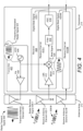
- FIG. 4 illustrates an example antenna array 212 and an example transceiver 214 of the radar system 102.
- the transceiver 214 includes a transmitter 402 and a receiver 404.
- the transmitter 402 includes at least one voltage-controlled oscillator 406 and at least one power amplifier 408.
- the receiver 404 includes at least two receive channels 410-1 to 410-M, where M is a positive integer greater than one.
- Each receive channel 410-1 to 410-M includes at least one low-noise amplifier 412, at least one mixer 414, at least one filter 416, and at least one analog-to-digital converter 418.
- the antenna array 212 includes at least one transmit antenna element 420 and at least two receive antenna elements 422-1 to 422-M.
- the transmit antenna element 420 is coupled to the transmitter 402.
- the receive antenna elements 422-1 to 422-M are respectively coupled to the receive channels 410-1 to 410-M.
- the voltage-controlled oscillator 406 During transmission, the voltage-controlled oscillator 406 generates a frequency-modulated radar signal 424 at radio frequencies.
- the power amplifier 408 amplifies the frequency-modulated radar signal 424 for transmission via the transmit antenna element 420.
- the transmitted frequency-modulated radar signal 424 is represented by the radar transmit signal 306, which can include multiple chirps 310-1 to 310-N based on the radar framing structure 314 of FIG. 3-2 .
- the radar transmit signal 306 is generated according to the burst-mode feature frame 322 of FIG. 3-2 and includes 16 chirps 310 (e.g., N equals 16).
- each receive antenna element 422-1 to 422-M receives a version of the radar receive signal 308-1 to 308-M.
- relative phase differences between these versions of the radar receive signals 308-1 to 308-M are due to differences in locations of the receive antenna elements 422-1 to 422-M.
- the low-noise amplifier 412 amplifies the radar receive signal 308, and the mixer 414 mixes the amplified radar receive signal 308 with the frequency-modulated radar signal 424.
- the mixer performs a beating operation, which downconverts and demodulates the radar receive signal 308 to generate a beat signal 426.
- a frequency of the beat signal 426 (e.g., the beat frequency 312) represents a frequency difference between the frequency-modulated radar signal 424 and the radar receive signal 308, which is proportional to the slant range 304 of FIG. 3-1 .
- the beat signal 426 can include multiple frequencies, which represents reflections from different objects or portions of an object within the external environment. In some cases, these different objects move at different speeds, move in different directions, or are positioned at different slant ranges relative to the radar system 102.
- the filter 416 filters the beat signal 426, and the analog-to-digital converter 418 digitizes the filtered beat signal 426.
- the receive channels 410-1 to 410-M respectively generate digital beat signals 428-1 to 428-M, which are provided to the system processor 216 for processing.
- the receive channels 410-1 to 410-M of the transceiver 214 are coupled to the system processor 216, as shown in FIG. 5 .
- FIG. 5 illustrates an example scheme implemented by the radar system 102 for performing ambient computing.
- the system processor 216 implements the hardware-abstraction module 220, the ambient-computing machine-learned module 222, and the gesture debouncer 224.
- the system processor 216 is connected to the receive channels 410-1 to 410-M and can also communicate with the computer processor 202 (of FIG. 2 ).
- the hardware-abstraction module 220, the ambient-computing machine-learned module 222, and/or the gesture debouncer 224 can alternatively be implemented by the computer processor 202.
- the hardware-abstraction module 220 accepts the digital beat signals 428-1 to 428-M from the receive channels 410-1 to 410-M.
- the digital beat signals 428-1 to 428-M represent raw or unprocessed complex data.
- the hardware-abstraction module 220 performs one or more operations to generate complex radar data 502-1 to 502-M based on digital beat signals 428-1 to 428-M.
- the hardware-abstraction module 220 transforms the complex data provided by the digital beat signals 428-1 to 428-M into a form that is expected by the ambient-computing machine-learned module 222.
- the hardware-abstraction module 220 normalizes amplitudes associated with different transmit power levels or transforms the complex data into a frequency-domain representation.
- the complex radar data 502-1 to 502-M includes magnitude and phase information (e.g., in-phase and quadrature components or real and imaginary numbers).
- the complex radar data 502-1 to 502-M represents a range-Doppler map for each receive channel 410-1 to 410-M and for each active feature frame 318, as further described with respect to FIG. 6-2 .
- the range-Doppler maps include implicit instead of explicit angular information.
- the complex radar data 502-1 to 502-M includes explicit angular information.
- the hardware abstraction module 220 can perform digital beamforming to explicitly provide the angular information, such as in the form of a four-dimensional range-Doppler-azimuth-elevation map.
- the complex radar data 502-1 to 502-M can include complex interferometry data for each receive channel 410-1 to 410-M.
- the complex interferometry data is an orthogonal representation of the range-Doppler map.
- the complex radar data 502-1 to 502-M includes frequency-domain representations of the digital beat signals 428-1 to 428-M for an active feature frame 318.
- other implementations of the radar system 102 can provide the digital beat signals 428-1 to 428-M directly to the ambient-computing machine-learned module 222.
- the complex radar data 502-1 to 502-M includes at least Doppler information as well as spatial information for one or more dimensions (e.g., range, azimuth, or elevation).
- the complex radar data 502 can include a combination of any of the above examples.
- the complex radar data 502 can include magnitude information associated with the range-Doppler maps and complex interferometry data.
- the gesture-recognition performance of the radar system 102 can improve if the complex radar data 502-1 to 502-M includes implicit or explicit information regarding an angular position of the object 302. This implicit or explicit can include phase information within the range-Doppler maps, angular information determined using beamforming techniques, and/or complex interferometry data.
- the ambient-computing machine-learned module 222 can provide a probabilistic classification.
- the ambient-computing machine-learned module 222 can be able to predict, given a sample input, a probability distribution over a set of classes.
- the ambient-computing machine-learned module 222 can output, for each class, a probability that the sample input belongs to such class.
- the probability distribution over all possible classes can sum to one.
- the ambient-computing machine-learned module 222 analyzes the complex radar data 502-1 to 502-M and generates probabilities 504. Some of the probabilities 504 are associated with various gestures that the radar system 102 can recognize. Another one of the probabilities 504 can be associated with a background task (e.g., background noise or gestures that are not recognized by the radar system 102).
- the gesture debouncer 224 analyzes the probabilities 504 to determine whether or not a user performed a gesture. If the gesture debouncer 224 determines that a gesture occurred, the gesture debouncer 224 informs the computer processor 202 of an ambient computing event 506.
- the ambient computing event 506 includes a signal that identifies an input associated with ambient computing.
- the signal identifies the recognized gesture and/or passes a gesture-control input to an application 206.
- the computer processor 202 or the application 206 Based on the ambient computing event 506, the computer processor 202 or the application 206 performs an action associated with the detected gesture or gesture-control input.
- the ambient computing event 506 can be expanded to indicate other events, such as whether or not the user is present within a given distance.
- An example implementation of the hardware-abstraction module 220 is further described with respect to FIGs. 6-1 to 6-2 .
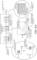
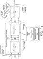
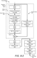
- FIG. 6-1 illustrates an example hardware-abstraction module 220 for ambient computing.
- the hardware-abstraction module 220 includes a pre-processing stage 602 and a signal-transformation stage 604.
- the pre-processing stage 602 operates on each chirp 310-1 to 310-N within the digital beat signals 428-1 to 428-M. In other words, the pre-processing stage 602 performs an operation for each active radar frame 324.
- the pre-processing stage 602 includes one-dimensional (1D) Fast-Fourier Transform (FFT) modules 606-1 to 606-M, which respectively process the digital beat signals 428-1 to 428-M.
- FFT Fast-Fourier Transform
- Other types of modules that perform similar operations are also possible, such as a Fourier Transform module.
- the signal-transformation stage 604 operates on the sequence of chirps 310-1 to 310-M within each of the digital beat signals 428-1 to 428-M. In other words, the signal-transformation stage 604 performs an operation for each active feature frame 318.
- the signal-transformation stage 604 includes buffers 608-1 to 608-M and two-dimensional (2D) FFT modules 610-1 to 610-M.
- the one-dimensional FFT modules 606-1 to 606-M perform individual FFT operations on the chirps 310-1 to 310-M within the digital beat signals 428-1 to 428-M. Assuming the radar receive signals 308-1 to 308-M include 16 chirps 310-1 to 310-N (e.g., N equals 16), each one-dimensional FFT module 606-1 to 606 M performs 16 FFT operations to generate pre-processed complex radar data per chirp 612-1 to 612-M. As the individual operations are performed, the buffers 608-1 to 608-M store the results.
- the information stored by the buffers 608-1 to 608-M represents pre-processed complex radar data per feature frame 614-1 to 614-M for the corresponding receive channels 410-1 to 410-M.
- Two-dimensional FFT modules 610-1 to 610-M respectively process the pre-processed complex radar data per feature frame 614-1 to 614-M to generate the complex radar data 502-1 to 502-M.
- the complex radar data 502-1 to 502-M represents range-Doppler maps, as further described with respect to FIG. 6-2 .
- FIG. 6-2 illustrates example complex radar data 502-1 generated by the hardware-abstraction module 220 for ambient computing.
- the hardware-abstraction module 220 is shown to process a digital beat signal 428-1 associated with the receive channel 410-1.
- the digital beat signal 428-1 includes the chirps 310-1 to 310-M, which are time-domain signals.
- the chirps 310-1 to 310-M are passed to the one-dimensional FFT module 606-1 in an order in which they are received and processed by the transceiver 214.
- the one-dimensional FFT module 606-1 performs an FFT operation on a first chirp 310-1 of the digital beat signal 428-1 at a first time.
- the buffer 608-1 stores a first portion of the pre-processed complex radar data 612-1, which is associated with the first chirp 310-1.
- the one-dimensional FFT module 606-1 continues to process subsequent chirps 310-2 to 310-N, and the buffer 608-1 continues to store the corresponding portions of the pre-processed complex radar data 612-1. This process continues until the buffer 608-1 stores a last portion of the pre-processed complex radar data 612-M, which is associated with the chirp 310-M.
- the buffer 608-1 stores pre-processed complex radar data associated with a particular feature frame 614-1.
- the pre-processed complex radar data per feature frame 614-1 represents magnitude information (as shown) and phase information (not shown) across different chirps 310-1 to 310-N and across different range bins 616-1 to 616-A (or range intervals), where A represents a positive integer.
- the two-dimensional FFT 610-1 accepts the pre-processed complex radar data per feature frame 614-1 and performs a two-dimensional FFT operation to form the complex radar data 502-1, which represents a range-Doppler map 620.
- the range-Doppler map 620 includes complex data for the range bins 616-1 to 616-A and Doppler bins 618-1 to 618-B (or Doppler-frequency intervals), where B represents a positive integer.
- each range bin 616-1 to 616-A and Doppler bin 618-1 to 618-B includes a complex number with real and/or imaginary parts that represent magnitude and phase information.
- the quantity of range bins 616-1 to 616-A can be on the order of tens or hundreds, such as 32, 64, or 128 (e.g., A equals 32, 64, or 128).
- the quantity of Doppler bins can be on the order of tens or hundreds, such as 16, 32, 64, or 124 (e.g., B equals 16, 32, 64, or 124).
- the quantity of range bins is 64 and the quantity of Doppler bins is 16.
- the quantity of range bins is 128 and the quantity of Doppler bins is 16.
- the quantity of range bins can reduce based on an expected slant range 304 of the gestures.
- the complex radar data 502-1, along with the complex radar data 502-2 to 502-M (of FIG. 6-1 ), are provided to the ambient-computing machine-learned module 222, as shown in FIG. 7-1 .
- the ambient-computing machine-learned module 222 groups the classes 708 according to three predictions.
- the three predictions can include a portrait prediction, a landscape prediction, or an omni prediction.
- Each prediction includes two or three classes 708.
- the portrait prediction includes the background class 712 and gesture classes 710 associated with the right swipe 112 and the left swipe 114.
- the landscape prediction includes the background class 712 and gesture classes 710 associated with the up swipe 118 and the down swipe 120.
- the omni prediction includes the background class 712 and a gesture class 710 associated with the omni swipe 124.
- the classes 708 are mutually exclusive within each prediction, however the classes 708 between two predictions may not be mutually exclusive.
- the right swipe 112 of the portrait prediction can correspond to the down swipe 120 of the landscape prediction.
- the left swipe 114 of the portrait prediction can correspond to the up swipe 118 of the landscape prediction.
- the gesture class 710 associated with the omni swipe 124 can correspond to any directional swipe in the other predictions.
- the probabilities 504 of the classes 708 sum up to one.
- the gesture debouncer 224 detects an ambient computing event 506 by evaluating the probabilities 504.
- the gesture debouncer 224 enables the radar system 102 to recognize gestures from a continuous data stream while keeping the false positive rate below a false-positive-rate threshold.
- the gesture debouncer 224 can utilize a first threshold 714 and/or a second threshold 716.
- a value of the first threshold 714 is determined so as to ensure that the radar system 102 can quickly and accurately recognize different gestures performed by different users.
- the value of the first threshold 714 can be determined experimentally to balance the radar system 102's responsiveness and false positive rate.
- the gesture debouncer 224 can determine that a gesture is performed if a probability 504 associated with a corresponding gesture class 710 is higher than the first threshold 714.
- the probability 504 for the gesture has to be higher than the first threshold 714 for multiple consecutive feature frames 318, such as two, three, or four consecutive feature frames 318.
- the gesture debouncer 224 can also use the second threshold 716 to keep the false positive rate below the false-positive-rate threshold. In particular, after the gesture is detected, the gesture debouncer 224 prevents another gesture from being detected until the probabilities 504 associated with the gesture classes 710 are less than the second threshold 716. In some implementations, the probabilities 504 of the gesture classes 710 have to be less than the second threshold 716 for multiple consecutive feature frames 318, such as two, three, or four consecutive feature frames 318. As an example, the second threshold 716 can be set to approximately 0.3%. An example operation of the gesture debouncer 224 is further described with respect to FIG. 7-2 .
- FIG. 7-2 illustrates an example graph 718 of probabilities 504 across multiple gesture frames 316.
- three probabilities 504-1, 504-2, and 504-3 are shown in the graph 718. These probabilities 504-1 to 504-3 are associated with different gesture classes 710. Although only three probabilities 504-1 to 504-3 are shown, the operations described below can apply to other implementations with other quantities of gesture classes 710 and probabilities 504.
- the probability 504 associated with the background class 712 is not explicitly shown for simplicity.
- the probabilities 504-1 to 504-3 are below the first threshold 714 and the second threshold 716 for gesture frames 316-1 and 316-2.
- the probability 504-2 is greater than the first threshold 714.
- the probabilities 504-1 and 504-3 are between the first threshold 714 and the second threshold 716 for the gesture frame 316-3.
- the probabilities 504-1 and 504-2 are above the first threshold 714 and the probability 504-3 is between the first threshold 714 and the second threshold 716.
- the probability 504-1 is greater than the first threshold 714
- the probability 504-2 is below the second threshold 716
- the probability 504-3 is between the first threshold 714 and the second threshold 716.
- the gesture debouncer 224 can detect an ambient computing event 506 responsive to one of the probabilities 504-1 to 504-3 being greater than the first threshold 714. In particular, the gesture debouncer 224 identifies a highest probability of the probabilities 504. If the highest probability is associated with one of the gesture classes 710 and not the background class 712, the gesture debouncer 224 detects the ambient computing event 506 associated with the gesture class 710 with the highest probability. In the case of the gesture frame 316-3, the gesture debouncer 224 can detect an ambient computing event 506 associated with the gesture class 710 that corresponds to the probability 504-2, which is greater than the first threshold 714.
- the gesture debouncer 224 can detect an ambient computing event 506 associated with the gesture class 710 that corresponds to the highest probability 504, which is the probability 504-2 in this example.
- the gesture debouncer 224 can detect an ambient computing event 506 responsive to a probability 504 being greater than the first threshold 714 for multiple consecutive gesture frames 316, such as two consecutive gesture frames 316. In this case, the gesture debouncer 224 does not detect an ambient computing event 506 at the gesture frame 316-3 because the probability 504-2 is below the first threshold 714 for the previous gesture frame 316-2. However, the gesture debouncer 224 detects the ambient computing event 506 at the gesture frame 316-4 because the probability 504-2 is greater than the first threshold 714 for the consecutive gesture frames 316-3 and 316-4. With this logic, the gesture debouncer 224 can also detect another ambient computing event 506 as occurring during the gesture frame 316-5 based on the probability 504-1 being greater than the first threshold 714 for the consecutive gesture frames 316-4 and 316-5.
- the gesture debouncer 224 can detect the ambient computing event 506 at the gesture frame 316-4 because the probabilities 504-1 to 504-3 were less than the second threshold 716 one or more gesture frames prior to the gesture frame 316-4 (e.g., at gesture frames 316-1 and 316-2). However, because the gesture debouncer 224 detects the ambient computing event 506 at the gesture frame 316-4, the gesture debouncer 224 does not detect another ambient computing event 506 at the gesture frame 316-5, even though the probability 504-1 is greater than the first threshold 714. This is because the probabilities 504-1 to 504-3 did not have a chance to decrease below the second threshold 716 for one or more gesture frames 316 after the ambient computing event 506 was detected at the gesture frame 316-4.
- a first example implementation of the ambient-computing machine-learned module 222 is described with respect to FIGs. 8-1 to 8-3 .
- This ambient-computing machine-learned module 222 is designed to recognize directional swipes and the omni swipe 124 of FIG. 1-2 .
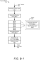
- a second example implementation of the ambient-computing machine-learned module 222 is described with respect to FIGs. 9-1 to 9-3 .
- This ambient-computing machine-learned module 222 is designed to recognize directional swipes and the tap gesture. Additionally, the ambient-computing machine-learned module 222 of FIGs. 9-1 to 9-3 enable recognition of gestures at farther distances compared to the ambient-computing machine-learned module 222 of FIGs. 8-1 to 8-3 .
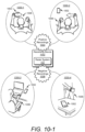
- the recording device 1002 aligns a timing window based on the detected center of the gesture motion.
- the timing window can have a particular duration. This duration can be associated with a particular quantity of feature frames 318, such as 12 or 30 feature frames 318. In general, the quantity of feature frames 318 is sufficient to capture the gestures associated with the gesture classes 710. In some cases, an additional offset is included within the timing window. The offset can be associated with a duration of one or more feature frames 318. A center of the timing window can be aligned with the detected center of the gesture motion.
- additional training data is generated by augmenting the recorded data.
- recorded data is augmented using magnitude scaling.
- magnitudes of the positive recordings 1004 and/or the negative recordings 1008 are scaled with a scaling factor chosen from a normal distribution.
- the normal distribution has a mean of 1 and a standard deviation of 0.025.
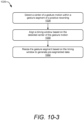
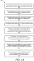
- a second phase described at 1210 includes performing an unsegmented recognition task using the ambient-computing machine-learned module and the gesture debouncer 224.
- the unsegmented recognition task is performed using continuous xwbrea (or a continuous data stream).
- a detection rate, and/or a false positive rate of the ambient-computing machine-learned module 222 can be evaluated.
- the unsegmented recognition task can be performed using the positive recordings 1004 to evaluate the detection rate, and the unsegmented recognition task can be performed using the negative recordings 1006 to evaluate the false positive rate.
- the unsegmented recognition task utilizes the gesture debouncer 224, which enables further tuning of the first threshold 714 and the second threshold 716 to achieve a desired detection rate and a desired false positive rate.
- FIGs. 13 to 15 depict example methods 1300, 1400, and 1500 for implementing aspects of ambient computing using a radar system.
- Methods 1300, 1400, and 1500 are shown as sets of operations (or acts) performed but not necessarily limited to the order or combinations in which the operations are shown herein. Further, any of one or more of the operations may be repeated, combined, reorganized, or linked to provide a wide array of additional and/or alternate methods.
- reference may be made to the environment 100-1 to 100-5 of FIG. 1 and entities detailed in FIG. 2 , 4 , 5 , and 7-1 , reference to which is made for example only.
- the techniques are not limited to performance by one entity or multiple entities operating on one device.
- a radar transmit signal comprising multiple frames is transmitted.
- Each frame of the multiple frames comprises multiple chirps.
- the radar system 102 transmits the radar transmit signal 306, as shown in FIG. 3-1 .
- the radar transmit signal 306 is associated with multiple feature frames 318, as shown in FIG. 3-2 .
- Each feature frame 318 includes multiple chirps 310, which are depicted within the active radar frames 324.
- the multiple feature frames 318 can correspond to a same gesture frame 316.
- probabilities associated with multiple gestures are generated by the second stage of the machine-learned module and based on the concatenated set of frame summaries.
- the temporal model 704 generates the probabilities 504 based on the concatenated set of frame summaries 840.
- the probabilities 504 are associated with multiple gestures or multiple gesture classes 710.
- Example gestures include directional swipes, an omni swipe, and a tap.
- One of the probabilities 504 can also be associated with a background task or a background class 712.
- a radar receive signal that is reflected by a user is received.
- the radar system 102 receives the radar receive signal 308, which is reflected by a user (or more generally the object 302), as shown in FIG. 3-1 .
- the complex radar data is processed using a machine-learned module.
- the machine-learned module has been trained, using supervised learning, to generate probabilities associated with multiple gestures.
- the complex radar data 502 is processed using the ambient-computing machine-learned module 222, as shown in FIG. 5 .
- the ambient-computing machine-learned module 222 has been trained, using supervised learning, to generate probabilities 504 associated with multiple gestures (e.g., multiple gestures classes 710), as shown in FIG. 7-1 .
- a gesture of the multiple gestures that has a highest probability of the probabilities is selected.
- the gesture debouncer 224 selects a gesture of the multiple gestures that has a highest probability of the probabilities 504.
- the gesture debouncer 224 selects the third probability 504-3 as the highest probability for the gesture frame 316-1.
- the gesture debouncer 224 selects the second probability 504-2 as the highest probability.
- the gesture debouncer 224 selects the first probability 504-1 as the highest probability.
- the highest probability is determined to be greater than a first threshold.
- the gesture debouncer 224 determines that the highest probability is greater than the first threshold.
- the gesture debouncer 224 determines that the highest probabilities within the gesture frames 316-1 and 316-2 (e.g., probabilities 504-3 and 504-2) are below the first threshold 714.
- the gesture debouncer 224 determines that the highest probability (e.g., probability 504-2) is greater than the first threshold 714.
- the first threshold 714 can be predetermined to realize a target responsiveness, a target detection rate, and/or a target false positive rate for the radar system 102. In general, increasing the first threshold 714 decreases the false positive rate of the radar system 102, but can decrease the responsiveness and decrease the detection rate. Likewise, decreasing the first threshold 714 can increase the responsiveness and/or the detection rate of the radar system 102 at the cost of increasing the false positive rate. In this way, the first threshold 714 can be chosen in a manner that optimizes the responsiveness, the detection rate, and the false positive rate of the radar system 102.
- a segmented classification task is performed using pre-segmented data and the machine-learned module to evaluate an error associated with classification of multiple gestures.
- the pre-segmented data comprises complex radar data with multiple gesture segments.
- Each gesture segment of the multiple gesture segments comprises a gesture motion. Centers of gesture motions across the multiple gestures segments have a same relative timing alignment within each gesture segment.
- the segmented classification task described at 1208 is performed using the pre-segmented data within the test data set.
- the pre-segmented data comprises complex radar data 502 having multiple gesture segments. Centers of gesture motions within each gesture segment is aligned according to the flow diagram 1026 of FIG. 10-3 .
- the error can represent an error in correctly identifying a gesture performed by a user.
- an unsegmented recognition task is performed using continuous time-series data, the machine-learned module, and a gesture debouncer to evaluate a false positive rate.
- the unsegmented recognition task is performed using continuous time-series data, as described at 1210 in FIG. 12 .
- the continuous time-series data is not pre-segmented.
- one or more elements of the machine-learned module are adjusted to reduce the error and the false positive rate.
- an overall architecture of the ambient-computing machine-learned module 222, adjustments to the training data, and/or adjustments to the hyperparameters can be adjusted to reduce the error and/or the false positive rate.
- FIG. 16 illustrates various components of an example computing system 1600 that can be implemented as any type of client, server, and/or computing device as described with reference to the previous FIG. 2 to implement aspects of training a machine-learned module to perform ambient computing.
- the computing system 1600 includes communication devices 1602 that enable wired and/or wireless communication of device data 1604 (e.g., received data, data that is being received, data scheduled for broadcast, or data packets of the data).
- the communication devices 1602 or the computing system 1600 can include one or more radar systems 102.
- the device data 1604 or other device content can include configuration settings of the device, media content stored on the device, and/or information associated with a user of the device.
- Media content stored on the computing system 1600 can include any type of audio, video, and/or image data.
- the computing system 1600 includes one or more data inputs 1606 via which any type of data, media content, and/or inputs can be received, such as human utterances, user-selectable inputs (explicit or implicit), messages, music, television media content, recorded video content, and any other type of audio, video, and/or image data received from any content and/or data source.
- data inputs 1606 via which any type of data, media content, and/or inputs can be received, such as human utterances, user-selectable inputs (explicit or implicit), messages, music, television media content, recorded video content, and any other type of audio, video, and/or image data received from any content and/or data source.
- the computing system 1600 also includes communication interfaces 1608, which can be implemented as any one or more of a serial and/or parallel interface, a wireless interface, any type of network interface, a modem, and as any other type of communication interface.
- the communication interfaces 1608 provide a connection and/or communication links between the computing system 1600 and a communication network by which other electronic, computing, and communication devices communicate data with the computing system 1600.
- the computing system 1600 includes one or more processors 1610 (e.g., any of microprocessors, controllers, and the like), which process various computer-executable instructions to control the operation of the computing system 1600.
- processors 1610 e.g., any of microprocessors, controllers, and the like
- the computing system 1600 can be implemented with any one or combination of hardware, firmware, or fixed logic circuitry that is implemented in connection with processing and control circuits which are generally identified at 1612.
- the computing system 1600 can include a system bus or data transfer system that couples the various components within the device.
- a system bus can include any one or combination of different bus structures, such as a memory bus or memory controller, a peripheral bus, a universal serial bus, and/or a processor or local bus that utilizes any of a variety of bus architectures.
- the computing system 1600 also includes a computer-readable medium 1614, such as one or more memory devices that enable persistent and/or non-transitory data storage (i.e., in contrast to mere signal transmission), examples of which include random access memory (RAM), non-volatile memory (e.g., any one or more of a read-only memory (ROM), flash memory, EPROM, EEPROM, etc.), and a disk storage device.
- RAM random access memory
- non-volatile memory e.g., any one or more of a read-only memory (ROM), flash memory, EPROM, EEPROM, etc.
- the disk storage device may be implemented as any type of magnetic or optical storage device, such as a hard disk drive, a recordable and/or rewriteable compact disc (CD), any type of a digital versatile disc (DVD), and the like.
- the computing system 1600 can also include a mass storage medium device (storage medium) 1616.
- the computer-readable medium 1614 provides data storage mechanisms to store the device data 1604, as well as various device applications 1618 and any other types of information and/or data related to operational aspects of the computing system 1600.
- an operating system 1620 can be maintained as a computer application with the computer-readable medium 1614 and executed on the processors 1610.
- the device applications 1618 may include a device manager, such as any form of a control application, software application, signal-processing and control module, code that is native to a particular device, a hardware abstraction layer for a particular device, and so on.
- the device applications 1618 also include any system components, engines, or managers to implement ambient computing.
- the device applications 1618 include the application 206, the ambient-computing machine-learned module 222, and the gesture debouncer 224 of FIG. 2 .
Landscapes
- Engineering & Computer Science (AREA)
- Theoretical Computer Science (AREA)
- Physics & Mathematics (AREA)
- General Physics & Mathematics (AREA)
- General Engineering & Computer Science (AREA)
- Software Systems (AREA)
- Artificial Intelligence (AREA)
- Evolutionary Computation (AREA)
- Data Mining & Analysis (AREA)
- Mathematical Physics (AREA)
- Computing Systems (AREA)
- Radar, Positioning & Navigation (AREA)
- Remote Sensing (AREA)
- Computational Linguistics (AREA)
- Biophysics (AREA)
- Molecular Biology (AREA)
- General Health & Medical Sciences (AREA)
- Biomedical Technology (AREA)
- Life Sciences & Earth Sciences (AREA)
- Health & Medical Sciences (AREA)
- Computer Networks & Wireless Communication (AREA)
- Signal Processing (AREA)
- Human Computer Interaction (AREA)
- Computer Vision & Pattern Recognition (AREA)
- Medical Informatics (AREA)
- User Interface Of Digital Computer (AREA)
Claims (15)
- Verfahren zum Trainieren eines maschinengelernten Moduls (222), wobei das Verfahren gekennzeichnet ist durch
Bewerten des maschinengelernten Moduls (222) unter Verwendung eines zweiphasigen Prozesses, wobei das Bewerten umfasst:Durchführen einer segmentierten Klassifizierungsaufgabe unter Verwendung des maschinengelernten Moduls (222) unter Verwendung von vorsegmentierten Daten, um einen Fehler zu bewerten, der der Klassifizierung mehrerer Gesten zugeordnet ist, wobei die vorsegmentierten Daten komplexe Radardaten umfassen, die mehrere Gestensegmente aufweisen, wobei jedes Gestensegment der mehreren Gestensegmente eine Gestenbewegung umfasst, wobei Mittelpunkte der Gestenbewegungen über die mehreren Gestensegmente eine gleiche relative zeitliche Ausrichtung innerhalb jedes Gestensegments aufweisen;Durchführen einer unsegmentierten Erkennungsaufgabe unter Verwendung des maschinengelernten Moduls (222) unter Verwendung kontinuierlicher Zeitreihendaten zum Bewerten einer Falsch-Positiv-Rate, wobei die kontinuierlichen Zeitreihendaten andere komplexe Radardaten (502-1 - 502-M) umfassen, undAnpassen eines oder mehrerer Elemente des maschinengelernten Moduls (222), um den Fehler und die Falsch-Positiv-Rate zu reduzieren, wobei diese Elemente eine Gesamtarchitektur des maschinengelernten Umgebungsrechenmoduls (222), die Trainingsdaten und/oder die Hyperparameter beinhalten. - Verfahren nach Anspruch 1, wobei die kontinuierlichen Zeitreihendaten nicht zeitlich segmentiert sind.
- Verfahren nach Anspruch 1 oder 2, wobei die kontinuierlichen Zeitreihendaten negative Aufzeichnungen umfassen, die mindestens einem Benutzer zugeordnet sind, der sich auf natürliche Weise bewegt oder sich wiederholende Bewegungen durchführt, die den mehreren Gesten ähnlich sind.
- Verfahren nach einem vorhergehenden Anspruch, ferner umfassend:Training der inneren Parameter des maschinengelernten Moduls (222) unter Verwendung von zweiten vorsegmentierten Daten vor dem Bewerten des maschinengelernten Moduls (222); undOptimieren von Hyperparametern des maschinengelernten Moduls (222) unter Verwendung von dritten vorsegmentierten Daten vor dem Bewerten des maschinengelernten Moduls (222).
- Verfahren nach einem vorhergehenden Anspruch, ferner umfassend:
Anwenden eines zufälligen Versatzes auf die vorsegmentierten Daten und die kontinuierlichen Zeitreihendaten vor dem Bewerten des maschinengelernten Moduls (222). - Verfahren nach Anspruch 5, wobei das Anwenden des zufälligen Versatzes mindestens eines von Folgendem umfasst:Anwenden einer Phasendrehung auf die komplexen Radardaten (502-1 - 502-M); oderAnwenden von Magnitudenskalieren auf die komplexen Radardaten (502-1 - 502-M).
- Verfahren nach einem vorhergehenden Anspruch, ferner umfassend:
Erzeugen der vorsegmentierten Daten vor dem Durchführen der segmentierten Klassifizierungsaufgabe, wobei das Erzeugen der vorsegmentierten Daten Folgendes umfasst:Detektieren des Mittelpunkts einer Gestenbewegung innerhalb jedes segmentierten Bereichs einer positiven Aufzeichnung;Ausrichten eines Zeitfensters basierend auf dem detektierten Mittelpunkt der Gestenbewegung; undGrößenändern des Gestensegments basierend auf dem Zeitfenster, um die vorsegmentierten Daten zu erzeugen. - Verfahren nach Anspruch 7, wobei das Detektieren des Mittelpunkts der Gestenbewegung das Detektieren eines Null-Doppler-Übergangs in jedem Gestensegment der positiven Aufzeichnung umfasst.
- Verfahren nach einem der vorhergehenden Ansprüche, wobei die vorsegmentierten Daten Folgendes umfassen:positive Datensätze, die mindestens einem Benutzer zugeordnet sind, der die mehreren Gesten durchführt; undnegative Aufzeichnungen, die mindestens einem Benutzer zugeordnet sind, der sich auf natürliche Weise bewegt oder sich wiederholende Bewegungen durchführt, die den mehreren Gesten ähnlich sind.
- Verfahren nach Anspruch 9, wobei die positiven Aufzeichnungen und negativen Aufzeichnungen die komplexen Radardaten (502-1 - 502-M) umfassen, die durch ein Radarsystem aufgezeichnet sind.
- Verfahren nach Anspruch 10, wobei die komplexen Radardaten (502-1 - 502-M) komplexe Entfernungs-Doppler-Karten (620) darstellen, die mehreren Empfangskanälen zugeordnet sind.
- Verfahren nach einem der Ansprüche 10 oder 11, wobei die positiven Aufzeichnungen dem mindestens einen Benutzer zugeordnet sind, der jede Geste der mehreren Gesten mehrmals in unterschiedlichen Entfernungen von dem Radarsystem und/oder in unterschiedlichen Winkeln relativ zu dem Radarsystem durchführt.
- Verfahren nach einem vorhergehenden Anspruch, wobei der Fehler eine Situation darstellt, in der das maschinengelernten Modul (222) eine von einem Benutzer durchgeführte Geste falsch klassifiziert oder eine von dem Benutzer durchgeführte Bewegung im Hintergrund falsch als Geste klassifiziert.
- Verfahren nach einem vorhergehenden Anspruch, ferner umfassend:Durchführen einer weiteren unsegmentierten Erkennungsaufgabe zum Bewerten einer Detektionsrate; undAnpassen eines oder mehrerer Elemente, um die Detektionsrate zu erhöhen.
- System, umfassend ein Radarsystem und einen Prozessor, wobei der Prozessor dazu konfiguriert ist, komplexe Radardaten (502-1 - 502-M), die durch das Radarsystem erzeugt werden, nach einem maschinengelernten Modul (222) zu verarbeiten, das nach einem der Ansprüche 1-14 trainiert wurde.
Applications Claiming Priority (2)
| Application Number | Priority Date | Filing Date | Title |
|---|---|---|---|
| US202163173082P | 2021-04-09 | 2021-04-09 | |
| PCT/US2022/071646 WO2022217288A1 (en) | 2021-04-09 | 2022-04-08 | Training machine-learned modules for radar-based gesture detection in an ambient compute environment |
Publications (2)
| Publication Number | Publication Date |
|---|---|
| EP4320552A1 EP4320552A1 (de) | 2024-02-14 |
| EP4320552B1 true EP4320552B1 (de) | 2025-07-02 |
Family
ID=81603712
Family Applications (3)
| Application Number | Title | Priority Date | Filing Date |
|---|---|---|---|
| EP22723526.4A Pending EP4320554A1 (de) | 2021-04-09 | 2022-04-08 | Verwendung eines maschinell erlernten moduls zur radarbasierten gestenerkennung in einer umgebungscomputerumgebung |
| EP22722987.9A Pending EP4320553A1 (de) | 2021-04-09 | 2022-04-08 | Verwendung eines maschinell erlernten moduls zur radarbasierten gestenerkennung in einer umgebungscomputerumgebung |
| EP22722986.1A Active EP4320552B1 (de) | 2021-04-09 | 2022-04-08 | Training von maschinengelernten modulen zur radarbasierten gestenerkennung in einer umgebungsberechnungsumgebung |
Family Applications Before (2)
| Application Number | Title | Priority Date | Filing Date |
|---|---|---|---|
| EP22723526.4A Pending EP4320554A1 (de) | 2021-04-09 | 2022-04-08 | Verwendung eines maschinell erlernten moduls zur radarbasierten gestenerkennung in einer umgebungscomputerumgebung |
| EP22722987.9A Pending EP4320553A1 (de) | 2021-04-09 | 2022-04-08 | Verwendung eines maschinell erlernten moduls zur radarbasierten gestenerkennung in einer umgebungscomputerumgebung |
Country Status (4)
| Country | Link |
|---|---|
| US (2) | US12265666B2 (de) |
| EP (3) | EP4320554A1 (de) |
| CN (3) | CN117203640A (de) |
| WO (3) | WO2022217290A1 (de) |
Families Citing this family (3)
| Publication number | Priority date | Publication date | Assignee | Title |
|---|---|---|---|---|
| EP4320554A1 (de) | 2021-04-09 | 2024-02-14 | Google LLC | Verwendung eines maschinell erlernten moduls zur radarbasierten gestenerkennung in einer umgebungscomputerumgebung |
| EP4390456A1 (de) * | 2022-12-19 | 2024-06-26 | Aptiv Technologies Limited | Strahlvektorfilterung und -disambiguierung unter verwendung eines geschwindigkeitsprofilmusters für ego-bewegung eines niedrigradars |
| US12366925B2 (en) | 2023-06-27 | 2025-07-22 | Samsung Electronics Co., Ltd. | Robustifying radar-based gesture recognition solution using contextual information |
Family Cites Families (29)
| Publication number | Priority date | Publication date | Assignee | Title |
|---|---|---|---|---|
| US9880632B2 (en) * | 2014-06-19 | 2018-01-30 | Thalmic Labs Inc. | Systems, devices, and methods for gesture identification |
| US10481696B2 (en) * | 2015-03-03 | 2019-11-19 | Nvidia Corporation | Radar based user interface |
| DE102016214391B4 (de) * | 2016-08-03 | 2020-12-10 | Carl Zeiss Industrielle Messtechnik Gmbh | Verfahren zum Steuern eines Betriebes eines Koordinatenmessgerätes und Koordinatenmessgerät mit Steuerung |
| WO2018031516A1 (en) * | 2016-08-09 | 2018-02-15 | Google Llc | Radar-based gestural interface |
| US10845477B2 (en) * | 2017-05-10 | 2020-11-24 | Google Llc | Power management using a low-power radar |
| CN110959160B (zh) * | 2017-08-01 | 2024-12-20 | 华为技术有限公司 | 一种手势识别方法、装置及设备 |
| CN112041784A (zh) * | 2017-11-30 | 2020-12-04 | 脸谱科技有限责任公司 | 用于离散和连续手势的同时检测的方法和装置 |
| US20190383903A1 (en) * | 2018-06-13 | 2019-12-19 | KaiKuTek Inc. | Gesture recognition system having machine-learning accelerator |
| US10890653B2 (en) * | 2018-08-22 | 2021-01-12 | Google Llc | Radar-based gesture enhancement for voice interfaces |
| US10770035B2 (en) * | 2018-08-22 | 2020-09-08 | Google Llc | Smartphone-based radar system for facilitating awareness of user presence and orientation |
| US10698603B2 (en) * | 2018-08-24 | 2020-06-30 | Google Llc | Smartphone-based radar system facilitating ease and accuracy of user interactions with displayed objects in an augmented-reality interface |
| US11068942B2 (en) * | 2018-10-19 | 2021-07-20 | Cerebri AI Inc. | Customer journey management engine |
| CN109583436B (zh) * | 2019-01-29 | 2023-09-12 | 杭州朗阳科技有限公司 | 一种基于毫米波雷达的手势识别系统 |
| EP3963355A1 (de) * | 2019-03-08 | 2022-03-09 | OSRAM GmbH | Komponente für ein lidar-sensorsystem, lidar-sensorsystem, lidar-sensorvorrichtung, verfahren für ein lidar-sensorsystem und verfahren für eine lidar-sensorvorrichtung |
| US11550031B2 (en) * | 2019-03-18 | 2023-01-10 | Samsung Electronics Co., Ltd. | Method and apparatus for biometric authentication using face radar signal |
| US11126885B2 (en) * | 2019-03-21 | 2021-09-21 | Infineon Technologies Ag | Character recognition in air-writing based on network of radars |
| CN110084209B (zh) * | 2019-04-30 | 2022-06-24 | 电子科技大学 | 基于父子分类器的实时性手势识别方法 |
| US11442550B2 (en) * | 2019-05-06 | 2022-09-13 | Samsung Electronics Co., Ltd. | Methods for gesture recognition and control |
| US11385722B2 (en) * | 2019-07-26 | 2022-07-12 | Google Llc | Robust radar-based gesture-recognition by user equipment |
| JP7481434B2 (ja) * | 2019-10-30 | 2024-05-10 | グーグル エルエルシー | 空間時間ニューラルネットワークを使用してジェスチャ認識を実行するスマートデバイスベースのレーダシステム |
| WO2021107958A1 (en) * | 2019-11-27 | 2021-06-03 | Google Llc | Detecting a frame-of-reference change in a smart-device-based radar system |
| US11467254B2 (en) * | 2020-02-27 | 2022-10-11 | Samsung Electronics Co., Ltd. | Method and apparatus of radar-based activity detection |
| CN111460976B (zh) * | 2020-03-30 | 2023-06-06 | 上海交通大学 | 一种数据驱动的基于rgb视频的实时手部动作评估方法 |
| CN111488823B (zh) * | 2020-04-09 | 2022-07-08 | 福州大学 | 基于二维激光雷达的增维手势识别与交互系统及方法 |
| CN111695420B (zh) * | 2020-04-30 | 2024-03-08 | 华为技术有限公司 | 一种手势识别方法以及相关装置 |
| WO2022139783A1 (en) * | 2020-12-21 | 2022-06-30 | Intel Corporation | High end imaging radar |
| EP4050460B1 (de) * | 2021-02-24 | 2025-07-16 | Infineon Technologies AG | Radarbasierte objektverfolgung unter verwendung eines neuronalen netzes |
| EP4320554A1 (de) | 2021-04-09 | 2024-02-14 | Google LLC | Verwendung eines maschinell erlernten moduls zur radarbasierten gestenerkennung in einer umgebungscomputerumgebung |
| EP4163666A1 (de) * | 2021-10-05 | 2023-04-12 | Infineon Technologies AG | Radarbasierte bewegungsklassifizierung unter verwendung einer oder mehrerer zeitreihen |
-
2022
- 2022-04-08 EP EP22723526.4A patent/EP4320554A1/de active Pending
- 2022-04-08 EP EP22722987.9A patent/EP4320553A1/de active Pending
- 2022-04-08 WO PCT/US2022/071648 patent/WO2022217290A1/en not_active Ceased
- 2022-04-08 WO PCT/US2022/071646 patent/WO2022217288A1/en not_active Ceased
- 2022-04-08 CN CN202280024774.0A patent/CN117203640A/zh active Pending
- 2022-04-08 EP EP22722986.1A patent/EP4320552B1/de active Active
- 2022-04-08 CN CN202280024776.XA patent/CN117203641A/zh active Pending
- 2022-04-08 US US18/554,337 patent/US12265666B2/en active Active
- 2022-04-08 CN CN202280024782.5A patent/CN117321604A/zh active Pending
- 2022-04-08 WO PCT/US2022/071647 patent/WO2022217289A1/en not_active Ceased
-
2025
- 2025-02-28 US US19/067,229 patent/US20250238085A1/en active Pending
Also Published As
| Publication number | Publication date |
|---|---|
| WO2022217288A1 (en) | 2022-10-13 |
| EP4320554A1 (de) | 2024-02-14 |
| EP4320553A1 (de) | 2024-02-14 |
| US12265666B2 (en) | 2025-04-01 |
| CN117203640A (zh) | 2023-12-08 |
| US20240231505A1 (en) | 2024-07-11 |
| CN117203641A (zh) | 2023-12-08 |
| EP4320552A1 (de) | 2024-02-14 |
| US20250238085A1 (en) | 2025-07-24 |
| WO2022217289A1 (en) | 2022-10-13 |
| WO2022217290A1 (en) | 2022-10-13 |
| CN117321604A (zh) | 2023-12-29 |
Similar Documents
| Publication | Publication Date | Title |
|---|---|---|
| US12055656B2 (en) | Detecting a frame-of-reference change in a smart-device-based radar system | |
| US12158991B2 (en) | Smart-device-based radar system performing gesture recognition using a space time neural network | |
| US20250238085A1 (en) | Training a Machine-Learned Module for Radar-Based Gesture Detection in an Ambient Compute Environment | |
| Liu et al. | M-gesture: Person-independent real-time in-air gesture recognition using commodity millimeter wave radar | |
| JP7340656B2 (ja) | 電子機器およびソフトウェアプログラム | |
| JP6816201B2 (ja) | タイプに依存しないrf信号表現 | |
| US20230161027A1 (en) | Smart-Device-Based Radar System Performing Near-Range Detection | |
| US20210190902A1 (en) | Smart-Device-Based Radar System Performing Symmetric Doppler Interference Mitigation | |
| US20240027600A1 (en) | Smart-Device-Based Radar System Performing Angular Position Estimation | |
| Li et al. | Di-gesture: Domain-independent and real-time gesture recognition with millimeter-wave signals | |
| EP4275105A1 (de) | Systeme und verfahren zur verwaltung der bewegungsdetektion einer elektronischen vorrichtung und zugehörige elektronische vorrichtungen | |
| EP4348292A1 (de) | Programmierschnittstelle für radaranwendungen | |
| US20250189629A1 (en) | Providing Radar Sensing for Multiple Applications | |
| US20230400564A1 (en) | Systems and methods for managing motion detection of an electronic device, and associated electronic devices |
Legal Events
| Date | Code | Title | Description |
|---|---|---|---|
| STAA | Information on the status of an ep patent application or granted ep patent |
Free format text: STATUS: UNKNOWN |
|
| STAA | Information on the status of an ep patent application or granted ep patent |
Free format text: STATUS: THE INTERNATIONAL PUBLICATION HAS BEEN MADE |
|
| PUAI | Public reference made under article 153(3) epc to a published international application that has entered the european phase |
Free format text: ORIGINAL CODE: 0009012 |
|
| STAA | Information on the status of an ep patent application or granted ep patent |
Free format text: STATUS: REQUEST FOR EXAMINATION WAS MADE |
|
| 17P | Request for examination filed |
Effective date: 20230913 |
|
| AK | Designated contracting states |
Kind code of ref document: A1 Designated state(s): AL AT BE BG CH CY CZ DE DK EE ES FI FR GB GR HR HU IE IS IT LI LT LU LV MC MK MT NL NO PL PT RO RS SE SI SK SM TR |
|
| DAV | Request for validation of the european patent (deleted) | ||
| DAX | Request for extension of the european patent (deleted) | ||
| GRAP | Despatch of communication of intention to grant a patent |
Free format text: ORIGINAL CODE: EPIDOSNIGR1 |
|
| STAA | Information on the status of an ep patent application or granted ep patent |
Free format text: STATUS: GRANT OF PATENT IS INTENDED |
|
| RIC1 | Information provided on ipc code assigned before grant |
Ipc: G06N 20/00 20190101ALI20250220BHEP Ipc: G06N 5/01 20230101ALI20250220BHEP Ipc: G06N 3/082 20230101ALI20250220BHEP Ipc: G06N 3/045 20230101ALI20250220BHEP Ipc: G01S 13/58 20060101ALI20250220BHEP Ipc: G01S 13/34 20060101ALI20250220BHEP Ipc: G01S 7/41 20060101ALI20250220BHEP Ipc: G01S 7/35 20060101ALI20250220BHEP Ipc: G06F 3/01 20060101ALI20250220BHEP Ipc: G06N 3/02 20060101AFI20250220BHEP |
|
| INTG | Intention to grant announced |
Effective date: 20250304 |
|
| GRAS | Grant fee paid |
Free format text: ORIGINAL CODE: EPIDOSNIGR3 |
|
| GRAA | (expected) grant |
Free format text: ORIGINAL CODE: 0009210 |
|
| STAA | Information on the status of an ep patent application or granted ep patent |
Free format text: STATUS: THE PATENT HAS BEEN GRANTED |
|
| P01 | Opt-out of the competence of the unified patent court (upc) registered |
Free format text: CASE NUMBER: APP_24247/2025 Effective date: 20250521 |
|
| AK | Designated contracting states |
Kind code of ref document: B1 Designated state(s): AL AT BE BG CH CY CZ DE DK EE ES FI FR GB GR HR HU IE IS IT LI LT LU LV MC MK MT NL NO PL PT RO RS SE SI SK SM TR |
|
| REG | Reference to a national code |
Ref country code: GB Ref legal event code: FG4D |
|
| REG | Reference to a national code |
Ref country code: CH Ref legal event code: EP |
|
| REG | Reference to a national code |
Ref country code: DE Ref legal event code: R096 Ref document number: 602022016890 Country of ref document: DE |
|
| REG | Reference to a national code |
Ref country code: IE Ref legal event code: FG4D |
|
| REG | Reference to a national code |
Ref country code: NL Ref legal event code: MP Effective date: 20250702 |
|
| PG25 | Lapsed in a contracting state [announced via postgrant information from national office to epo] |
Ref country code: PT Free format text: LAPSE BECAUSE OF FAILURE TO SUBMIT A TRANSLATION OF THE DESCRIPTION OR TO PAY THE FEE WITHIN THE PRESCRIBED TIME-LIMIT Effective date: 20251103 |
|
| PG25 | Lapsed in a contracting state [announced via postgrant information from national office to epo] |
Ref country code: NL Free format text: LAPSE BECAUSE OF FAILURE TO SUBMIT A TRANSLATION OF THE DESCRIPTION OR TO PAY THE FEE WITHIN THE PRESCRIBED TIME-LIMIT Effective date: 20250702 |
|
| REG | Reference to a national code |
Ref country code: AT Ref legal event code: MK05 Ref document number: 1810071 Country of ref document: AT Kind code of ref document: T Effective date: 20250702 |
|
| PG25 | Lapsed in a contracting state [announced via postgrant information from national office to epo] |
Ref country code: IS Free format text: LAPSE BECAUSE OF FAILURE TO SUBMIT A TRANSLATION OF THE DESCRIPTION OR TO PAY THE FEE WITHIN THE PRESCRIBED TIME-LIMIT Effective date: 20251102 |
|
| PG25 | Lapsed in a contracting state [announced via postgrant information from national office to epo] |
Ref country code: NO Free format text: LAPSE BECAUSE OF FAILURE TO SUBMIT A TRANSLATION OF THE DESCRIPTION OR TO PAY THE FEE WITHIN THE PRESCRIBED TIME-LIMIT Effective date: 20251002 |
|
| REG | Reference to a national code |
Ref country code: LT Ref legal event code: MG9D |
|
| PG25 | Lapsed in a contracting state [announced via postgrant information from national office to epo] |
Ref country code: AT Free format text: LAPSE BECAUSE OF FAILURE TO SUBMIT A TRANSLATION OF THE DESCRIPTION OR TO PAY THE FEE WITHIN THE PRESCRIBED TIME-LIMIT Effective date: 20250702 |
|
| PG25 | Lapsed in a contracting state [announced via postgrant information from national office to epo] |
Ref country code: FI Free format text: LAPSE BECAUSE OF FAILURE TO SUBMIT A TRANSLATION OF THE DESCRIPTION OR TO PAY THE FEE WITHIN THE PRESCRIBED TIME-LIMIT Effective date: 20250702 |
|
| PG25 | Lapsed in a contracting state [announced via postgrant information from national office to epo] |
Ref country code: HR Free format text: LAPSE BECAUSE OF FAILURE TO SUBMIT A TRANSLATION OF THE DESCRIPTION OR TO PAY THE FEE WITHIN THE PRESCRIBED TIME-LIMIT Effective date: 20250702 |
|
| PG25 | Lapsed in a contracting state [announced via postgrant information from national office to epo] |
Ref country code: GR Free format text: LAPSE BECAUSE OF FAILURE TO SUBMIT A TRANSLATION OF THE DESCRIPTION OR TO PAY THE FEE WITHIN THE PRESCRIBED TIME-LIMIT Effective date: 20251003 |
|
| PG25 | Lapsed in a contracting state [announced via postgrant information from national office to epo] |
Ref country code: SE Free format text: LAPSE BECAUSE OF FAILURE TO SUBMIT A TRANSLATION OF THE DESCRIPTION OR TO PAY THE FEE WITHIN THE PRESCRIBED TIME-LIMIT Effective date: 20250702 Ref country code: CZ Free format text: LAPSE BECAUSE OF FAILURE TO SUBMIT A TRANSLATION OF THE DESCRIPTION OR TO PAY THE FEE WITHIN THE PRESCRIBED TIME-LIMIT Effective date: 20250702 |
|
| PG25 | Lapsed in a contracting state [announced via postgrant information from national office to epo] |
Ref country code: LV Free format text: LAPSE BECAUSE OF FAILURE TO SUBMIT A TRANSLATION OF THE DESCRIPTION OR TO PAY THE FEE WITHIN THE PRESCRIBED TIME-LIMIT Effective date: 20250702 |
|
| PG25 | Lapsed in a contracting state [announced via postgrant information from national office to epo] |
Ref country code: PL Free format text: LAPSE BECAUSE OF FAILURE TO SUBMIT A TRANSLATION OF THE DESCRIPTION OR TO PAY THE FEE WITHIN THE PRESCRIBED TIME-LIMIT Effective date: 20250702 Ref country code: BG Free format text: LAPSE BECAUSE OF FAILURE TO SUBMIT A TRANSLATION OF THE DESCRIPTION OR TO PAY THE FEE WITHIN THE PRESCRIBED TIME-LIMIT Effective date: 20250702 |
|
| PG25 | Lapsed in a contracting state [announced via postgrant information from national office to epo] |
Ref country code: RS Free format text: LAPSE BECAUSE OF FAILURE TO SUBMIT A TRANSLATION OF THE DESCRIPTION OR TO PAY THE FEE WITHIN THE PRESCRIBED TIME-LIMIT Effective date: 20251002 |
|
| PG25 | Lapsed in a contracting state [announced via postgrant information from national office to epo] |
Ref country code: ES Free format text: LAPSE BECAUSE OF FAILURE TO SUBMIT A TRANSLATION OF THE DESCRIPTION OR TO PAY THE FEE WITHIN THE PRESCRIBED TIME-LIMIT Effective date: 20250702 |
|
| PG25 | Lapsed in a contracting state [announced via postgrant information from national office to epo] |
Ref country code: SM Free format text: LAPSE BECAUSE OF FAILURE TO SUBMIT A TRANSLATION OF THE DESCRIPTION OR TO PAY THE FEE WITHIN THE PRESCRIBED TIME-LIMIT Effective date: 20250702 |
|
| PG25 | Lapsed in a contracting state [announced via postgrant information from national office to epo] |
Ref country code: DK Free format text: LAPSE BECAUSE OF FAILURE TO SUBMIT A TRANSLATION OF THE DESCRIPTION OR TO PAY THE FEE WITHIN THE PRESCRIBED TIME-LIMIT Effective date: 20250702 |
|
| PG25 | Lapsed in a contracting state [announced via postgrant information from national office to epo] |
Ref country code: IT Free format text: LAPSE BECAUSE OF FAILURE TO SUBMIT A TRANSLATION OF THE DESCRIPTION OR TO PAY THE FEE WITHIN THE PRESCRIBED TIME-LIMIT Effective date: 20250702 |
|
| PG25 | Lapsed in a contracting state [announced via postgrant information from national office to epo] |
Ref country code: SK Free format text: LAPSE BECAUSE OF FAILURE TO SUBMIT A TRANSLATION OF THE DESCRIPTION OR TO PAY THE FEE WITHIN THE PRESCRIBED TIME-LIMIT Effective date: 20250702 Ref country code: EE Free format text: LAPSE BECAUSE OF FAILURE TO SUBMIT A TRANSLATION OF THE DESCRIPTION OR TO PAY THE FEE WITHIN THE PRESCRIBED TIME-LIMIT Effective date: 20250702 |