EP4319611B1 - Surface cleaner - Google Patents
Surface cleaner Download PDFInfo
- Publication number
- EP4319611B1 EP4319611B1 EP22726847.1A EP22726847A EP4319611B1 EP 4319611 B1 EP4319611 B1 EP 4319611B1 EP 22726847 A EP22726847 A EP 22726847A EP 4319611 B1 EP4319611 B1 EP 4319611B1
- Authority
- EP
- European Patent Office
- Prior art keywords
- surface cleaner
- canister assembly
- cleaning
- hose
- fluid
- Prior art date
- Legal status (The legal status is an assumption and is not a legal conclusion. Google has not performed a legal analysis and makes no representation as to the accuracy of the status listed.)
- Active
Links
Images


Classifications
-
- A—HUMAN NECESSITIES
- A47—FURNITURE; DOMESTIC ARTICLES OR APPLIANCES; COFFEE MILLS; SPICE MILLS; SUCTION CLEANERS IN GENERAL
- A47L—DOMESTIC WASHING OR CLEANING; SUCTION CLEANERS IN GENERAL
- A47L5/00—Structural features of suction cleaners
- A47L5/12—Structural features of suction cleaners with power-driven air-pumps or air-compressors, e.g. driven by motor vehicle engine vacuum
- A47L5/22—Structural features of suction cleaners with power-driven air-pumps or air-compressors, e.g. driven by motor vehicle engine vacuum with rotary fans
- A47L5/225—Convertible suction cleaners, i.e. convertible between different types thereof, e.g. from upright suction cleaners to sledge-type suction cleaners
-
- A—HUMAN NECESSITIES
- A47—FURNITURE; DOMESTIC ARTICLES OR APPLIANCES; COFFEE MILLS; SPICE MILLS; SUCTION CLEANERS IN GENERAL
- A47L—DOMESTIC WASHING OR CLEANING; SUCTION CLEANERS IN GENERAL
- A47L11/00—Machines for cleaning floors, carpets, furniture, walls, or wall coverings
- A47L11/02—Floor surfacing or polishing machines
- A47L11/20—Floor surfacing or polishing machines combined with vacuum cleaning devices
- A47L11/201—Floor surfacing or polishing machines combined with vacuum cleaning devices with supply of cleaning agents
-
- A—HUMAN NECESSITIES
- A47—FURNITURE; DOMESTIC ARTICLES OR APPLIANCES; COFFEE MILLS; SPICE MILLS; SUCTION CLEANERS IN GENERAL
- A47L—DOMESTIC WASHING OR CLEANING; SUCTION CLEANERS IN GENERAL
- A47L11/00—Machines for cleaning floors, carpets, furniture, walls, or wall coverings
- A47L11/29—Floor-scrubbing machines characterised by means for taking-up dirty liquid
- A47L11/30—Floor-scrubbing machines characterised by means for taking-up dirty liquid by suction
-
- A—HUMAN NECESSITIES
- A47—FURNITURE; DOMESTIC ARTICLES OR APPLIANCES; COFFEE MILLS; SPICE MILLS; SUCTION CLEANERS IN GENERAL
- A47L—DOMESTIC WASHING OR CLEANING; SUCTION CLEANERS IN GENERAL
- A47L11/00—Machines for cleaning floors, carpets, furniture, walls, or wall coverings
- A47L11/34—Machines for treating carpets in position by liquid, foam, or vapour, e.g. by steam
-
- A—HUMAN NECESSITIES
- A47—FURNITURE; DOMESTIC ARTICLES OR APPLIANCES; COFFEE MILLS; SPICE MILLS; SUCTION CLEANERS IN GENERAL
- A47L—DOMESTIC WASHING OR CLEANING; SUCTION CLEANERS IN GENERAL
- A47L11/00—Machines for cleaning floors, carpets, furniture, walls, or wall coverings
- A47L11/40—Parts or details of machines not provided for in groups A47L11/02 - A47L11/38, or not restricted to one of these groups, e.g. handles, arrangements of switches, skirts, buffers, levers
- A47L11/4002—Installations of electric equipment
- A47L11/4005—Arrangements of batteries or cells; Electric power supply arrangements
-
- A—HUMAN NECESSITIES
- A47—FURNITURE; DOMESTIC ARTICLES OR APPLIANCES; COFFEE MILLS; SPICE MILLS; SUCTION CLEANERS IN GENERAL
- A47L—DOMESTIC WASHING OR CLEANING; SUCTION CLEANERS IN GENERAL
- A47L11/00—Machines for cleaning floors, carpets, furniture, walls, or wall coverings
- A47L11/40—Parts or details of machines not provided for in groups A47L11/02 - A47L11/38, or not restricted to one of these groups, e.g. handles, arrangements of switches, skirts, buffers, levers
- A47L11/4013—Contaminants collecting devices, i.e. hoppers, tanks or the like
- A47L11/4016—Contaminants collecting devices, i.e. hoppers, tanks or the like specially adapted for collecting fluids
-
- A—HUMAN NECESSITIES
- A47—FURNITURE; DOMESTIC ARTICLES OR APPLIANCES; COFFEE MILLS; SPICE MILLS; SUCTION CLEANERS IN GENERAL
- A47L—DOMESTIC WASHING OR CLEANING; SUCTION CLEANERS IN GENERAL
- A47L11/00—Machines for cleaning floors, carpets, furniture, walls, or wall coverings
- A47L11/40—Parts or details of machines not provided for in groups A47L11/02 - A47L11/38, or not restricted to one of these groups, e.g. handles, arrangements of switches, skirts, buffers, levers
- A47L11/4063—Driving means; Transmission means therefor
- A47L11/4069—Driving or transmission means for the cleaning tools
-
- A—HUMAN NECESSITIES
- A47—FURNITURE; DOMESTIC ARTICLES OR APPLIANCES; COFFEE MILLS; SPICE MILLS; SUCTION CLEANERS IN GENERAL
- A47L—DOMESTIC WASHING OR CLEANING; SUCTION CLEANERS IN GENERAL
- A47L11/00—Machines for cleaning floors, carpets, furniture, walls, or wall coverings
- A47L11/40—Parts or details of machines not provided for in groups A47L11/02 - A47L11/38, or not restricted to one of these groups, e.g. handles, arrangements of switches, skirts, buffers, levers
- A47L11/4075—Handles; levers
-
- A—HUMAN NECESSITIES
- A47—FURNITURE; DOMESTIC ARTICLES OR APPLIANCES; COFFEE MILLS; SPICE MILLS; SUCTION CLEANERS IN GENERAL
- A47L—DOMESTIC WASHING OR CLEANING; SUCTION CLEANERS IN GENERAL
- A47L11/00—Machines for cleaning floors, carpets, furniture, walls, or wall coverings
- A47L11/40—Parts or details of machines not provided for in groups A47L11/02 - A47L11/38, or not restricted to one of these groups, e.g. handles, arrangements of switches, skirts, buffers, levers
- A47L11/408—Means for supplying cleaning or surface treating agents
- A47L11/4083—Liquid supply reservoirs; Preparation of the agents, e.g. mixing devices
-
- A—HUMAN NECESSITIES
- A47—FURNITURE; DOMESTIC ARTICLES OR APPLIANCES; COFFEE MILLS; SPICE MILLS; SUCTION CLEANERS IN GENERAL
- A47L—DOMESTIC WASHING OR CLEANING; SUCTION CLEANERS IN GENERAL
- A47L11/00—Machines for cleaning floors, carpets, furniture, walls, or wall coverings
- A47L11/40—Parts or details of machines not provided for in groups A47L11/02 - A47L11/38, or not restricted to one of these groups, e.g. handles, arrangements of switches, skirts, buffers, levers
- A47L11/408—Means for supplying cleaning or surface treating agents
- A47L11/4088—Supply pumps; Spraying devices; Supply conduits
-
- A—HUMAN NECESSITIES
- A47—FURNITURE; DOMESTIC ARTICLES OR APPLIANCES; COFFEE MILLS; SPICE MILLS; SUCTION CLEANERS IN GENERAL
- A47L—DOMESTIC WASHING OR CLEANING; SUCTION CLEANERS IN GENERAL
- A47L5/00—Structural features of suction cleaners
- A47L5/12—Structural features of suction cleaners with power-driven air-pumps or air-compressors, e.g. driven by motor vehicle engine vacuum
- A47L5/22—Structural features of suction cleaners with power-driven air-pumps or air-compressors, e.g. driven by motor vehicle engine vacuum with rotary fans
- A47L5/28—Suction cleaners with handles and nozzles fixed on the casings, e.g. wheeled suction cleaners with steering handle
- A47L5/32—Suction cleaners with handles and nozzles fixed on the casings, e.g. wheeled suction cleaners with steering handle with means for connecting a hose
-
- A—HUMAN NECESSITIES
- A47—FURNITURE; DOMESTIC ARTICLES OR APPLIANCES; COFFEE MILLS; SPICE MILLS; SUCTION CLEANERS IN GENERAL
- A47L—DOMESTIC WASHING OR CLEANING; SUCTION CLEANERS IN GENERAL
- A47L5/00—Structural features of suction cleaners
- A47L5/12—Structural features of suction cleaners with power-driven air-pumps or air-compressors, e.g. driven by motor vehicle engine vacuum
- A47L5/22—Structural features of suction cleaners with power-driven air-pumps or air-compressors, e.g. driven by motor vehicle engine vacuum with rotary fans
- A47L5/36—Suction cleaners with hose between nozzle and casing; Suction cleaners for fixing on staircases; Suction cleaners for carrying on the back
- A47L5/365—Suction cleaners with hose between nozzle and casing; Suction cleaners for fixing on staircases; Suction cleaners for carrying on the back of the vertical type, e.g. tank or bucket type
-
- A—HUMAN NECESSITIES
- A47—FURNITURE; DOMESTIC ARTICLES OR APPLIANCES; COFFEE MILLS; SPICE MILLS; SUCTION CLEANERS IN GENERAL
- A47L—DOMESTIC WASHING OR CLEANING; SUCTION CLEANERS IN GENERAL
- A47L7/00—Suction cleaners adapted for additional purposes; Tables with suction openings for cleaning purposes; Containers for cleaning articles by suction; Suction cleaners adapted to cleaning of brushes; Suction cleaners adapted to taking-up liquids
- A47L7/0004—Suction cleaners adapted to take up liquids, e.g. wet or dry vacuum cleaners
-
- A—HUMAN NECESSITIES
- A47—FURNITURE; DOMESTIC ARTICLES OR APPLIANCES; COFFEE MILLS; SPICE MILLS; SUCTION CLEANERS IN GENERAL
- A47L—DOMESTIC WASHING OR CLEANING; SUCTION CLEANERS IN GENERAL
- A47L7/00—Suction cleaners adapted for additional purposes; Tables with suction openings for cleaning purposes; Containers for cleaning articles by suction; Suction cleaners adapted to cleaning of brushes; Suction cleaners adapted to taking-up liquids
- A47L7/0004—Suction cleaners adapted to take up liquids, e.g. wet or dry vacuum cleaners
- A47L7/0023—Recovery tanks
-
- A—HUMAN NECESSITIES
- A47—FURNITURE; DOMESTIC ARTICLES OR APPLIANCES; COFFEE MILLS; SPICE MILLS; SUCTION CLEANERS IN GENERAL
- A47L—DOMESTIC WASHING OR CLEANING; SUCTION CLEANERS IN GENERAL
- A47L9/00—Details or accessories of suction cleaners, e.g. mechanical means for controlling the suction or for effecting pulsating action; Storing devices specially adapted to suction cleaners or parts thereof; Carrying-vehicles specially adapted for suction cleaners
- A47L9/02—Nozzles
- A47L9/04—Nozzles with driven brushes or agitators
- A47L9/0405—Driving means for the brushes or agitators
- A47L9/0411—Driving means for the brushes or agitators driven by electric motor
-
- A—HUMAN NECESSITIES
- A47—FURNITURE; DOMESTIC ARTICLES OR APPLIANCES; COFFEE MILLS; SPICE MILLS; SUCTION CLEANERS IN GENERAL
- A47L—DOMESTIC WASHING OR CLEANING; SUCTION CLEANERS IN GENERAL
- A47L9/00—Details or accessories of suction cleaners, e.g. mechanical means for controlling the suction or for effecting pulsating action; Storing devices specially adapted to suction cleaners or parts thereof; Carrying-vehicles specially adapted for suction cleaners
- A47L9/22—Mountings for motor fan assemblies
-
- A—HUMAN NECESSITIES
- A47—FURNITURE; DOMESTIC ARTICLES OR APPLIANCES; COFFEE MILLS; SPICE MILLS; SUCTION CLEANERS IN GENERAL
- A47L—DOMESTIC WASHING OR CLEANING; SUCTION CLEANERS IN GENERAL
- A47L9/00—Details or accessories of suction cleaners, e.g. mechanical means for controlling the suction or for effecting pulsating action; Storing devices specially adapted to suction cleaners or parts thereof; Carrying-vehicles specially adapted for suction cleaners
- A47L9/24—Hoses or pipes; Hose or pipe couplings
- A47L9/242—Hose or pipe couplings
-
- A—HUMAN NECESSITIES
- A47—FURNITURE; DOMESTIC ARTICLES OR APPLIANCES; COFFEE MILLS; SPICE MILLS; SUCTION CLEANERS IN GENERAL
- A47L—DOMESTIC WASHING OR CLEANING; SUCTION CLEANERS IN GENERAL
- A47L9/00—Details or accessories of suction cleaners, e.g. mechanical means for controlling the suction or for effecting pulsating action; Storing devices specially adapted to suction cleaners or parts thereof; Carrying-vehicles specially adapted for suction cleaners
- A47L9/28—Installation of the electric equipment, e.g. adaptation or attachment to the suction cleaner; Controlling suction cleaners by electric means
- A47L9/2868—Arrangements for power supply of vacuum cleaners or the accessories thereof
- A47L9/2878—Dual-powered vacuum cleaners, i.e. devices which can be operated with mains power supply or by batteries
-
- A—HUMAN NECESSITIES
- A47—FURNITURE; DOMESTIC ARTICLES OR APPLIANCES; COFFEE MILLS; SPICE MILLS; SUCTION CLEANERS IN GENERAL
- A47L—DOMESTIC WASHING OR CLEANING; SUCTION CLEANERS IN GENERAL
- A47L9/00—Details or accessories of suction cleaners, e.g. mechanical means for controlling the suction or for effecting pulsating action; Storing devices specially adapted to suction cleaners or parts thereof; Carrying-vehicles specially adapted for suction cleaners
- A47L9/32—Handles
- A47L9/325—Handles for wheeled suction cleaners with steering handle
-
- A—HUMAN NECESSITIES
- A47—FURNITURE; DOMESTIC ARTICLES OR APPLIANCES; COFFEE MILLS; SPICE MILLS; SUCTION CLEANERS IN GENERAL
- A47L—DOMESTIC WASHING OR CLEANING; SUCTION CLEANERS IN GENERAL
- A47L9/00—Details or accessories of suction cleaners, e.g. mechanical means for controlling the suction or for effecting pulsating action; Storing devices specially adapted to suction cleaners or parts thereof; Carrying-vehicles specially adapted for suction cleaners
- A47L9/32—Handles
- A47L9/327—Handles for suction cleaners with hose between nozzle and casing
Definitions
- the present invention relates to surface cleaners, and more particularly, a wet surface cleaner with more than one cleaning mode.
- US6058559 disclosed an electric vacuum cleaner comprising a vacuum cleaner body, a hose connected to the vacuum cleaner body, a support pipe connected to the hose and a suction device connected to the support pipe.
- CA2658397 discloses a surface cleaning apparatus including a removably mounted portable surface cleaning apparatus and is re-configurable to two or more different cleaning configurations.
- US8943647 discloses a vacuum cleaner including a base having a foot suction nozzle and a hand assembly removably coupled to the foot.
- US2018/177368 discloses a vacuum cleaner which includes an air treatment or debris removal assembly with a multi-layer filtration stage.
- a surface cleaner including a body, a base pivotally coupled to the body and configured to move across a cleaning surface, a nozzle, a handle, and a canister assembly coupled to the body.
- the body has a lower portion and an upper portion opposite the lower portion, the upper portion including the handle.
- the base is coupled to the lower portion of the body.
- the nozzle is positioned on the base adjacent the cleaning surface.
- the canister assembly is removably coupled to the body.
- the canister assembly includes a housing, a supply tank, and a recovery tank.
- the surface cleaner further includes a hose having a first end coupled to the canister assembly fluidly connected to the recovery tank and a second end coupled to the base fluidly connected to the nozzle.
- a suction source is in fluid communication with the recovery tank and is operable to draw fluid and debris through the hose into the recovery tank.
- the surface cleaner is operable in an upright cleaning mode when the canister assembly is coupled to the body.
- the surface cleaner is operable in an auxiliary cleaning mode when the canister assembly is uncoupled from the body.
- the nozzle is movable over the cleaning surface by a user grasping the handle such that in operation debris and fluid are drawn through the nozzle, through the hose and into the recovery tank.
- the present disclosure relates to a surface cleaner, specifically a surface cleaner configured to recover and/or distribute cleaning liquid, with multiple different cleaning positions or modes.
- the surface cleaner includes an upright cleaning mode, an auxiliary cleaning mode, and a lift-off cleaning mode. It is beneficial for the user to be able to have one machine that is able to serve multiple purposes.
- the surface cleaner includes a canister assembly removably coupled to a body, the canister assembly having a housing, a recovery tank, and a supply tank. The surface cleaner operates in the upright cleaning mode when the canister assembly is coupled to the body. The surface cleaner operates in the auxiliary cleaning mode when the canister assembly is removed from the body.
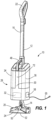
- Fig. 1 illustrates a perspective view of a surface cleaner 10 according to an embodiment of the invention.
- the surface cleaner 10 is a surface cleaner that delivers a liquid, such as an extractor, a hard floor cleaner, or the like.
- the surface cleaner 10 has a body 12 with a base 20 that supports the surface cleaner 10 on a cleaning surface.
- the body 12 includes a lower portion 14 and an upper portion 16 opposite the lower portion 14.
- the base 20 is pivotably coupled to the lower portion 14 and is configured to move across the cleaning surface.
- the upper portion 16 includes a handle 22, opposite the base 20.
- the base 20 is movable across the cleaning surface in an upright cleaning mode and an auxiliary cleaning mode by a user grasping the handle 22.
- the surface cleaner 10 includes a canister assembly 28 that is removably coupled to the body 12.
- the canister assembly 28 includes a housing 30, a suction source or motor 32, a supply tank 34, and a recovery tank 36.
- the canister assembly 28 is movable between a coupled position, illustrated in Figs. 1 and 10 , and an uncoupled position, illustrated in Figs. 2 , 3 , 7 , 8 , and 11 .
- a carrying handle 48 is positioned on the housing 30. The carrying handle 48 provides a user graspable portion to move the canister assembly 28 between the coupled position and the removed position.
- the canister assembly 28 may have different internal layouts of the motor 32, supply tank 34, and recovery tank 36.
- the supply tank 34 and the recovery tank 36 are in a side by side orientation.
- Side by side includes orientations where the supply tank 34 and the recovery tank 36 are adjacent and touching, as well as orientations where the supply tank 34 and the recovery tank 36 are separated by a frame portion 72, such as the housing 30 illustrated in Fig. 1 .
- the top end of the supply tank and the top end of the recovery tank are substantially the same level.
- the motor 32 is located at an elevation below the supply tank 34 and the recovery tank 36.
- the supply tank 34 is positioned above the recovery tank 36.
- the motor 32 is positioned at an elevation above the recovery tank 36 and adjacent the supply tank 34.
- the motor 32 is positioned at an elevation below both the recovery tank 36 and the supply tank 34.
- the surface cleaner 10 includes a nozzle 24 positioned on the base 20.
- the nozzle 24 is in fluid communication with the suction motor 32 and the recovery tank 36.
- the suction motor 32 generates a working airflow along an airpath extending from a suction inlet 52 on the nozzle 24 to an exhaust outlet 58, operable to draw debris and fluid from the cleaning surface through the suction inlet 52.
- the working airflow extends through the hose 40 and into the recovery tank 36.
- the hose 40 is coupled directly to the base 20 and is in fluid communication with the nozzle 24, allowing the suction motor 32 to draw fluid and debris from the nozzle 24 through the hose 40 into the recovery tank 36.
- the hose 40 is configured to be uncoupled from the base 20.
- the surface cleaner 10 includes a fluid distributor 50 positioned on the base 20.
- the fluid distributor 50 is in fluid communication with the supply tank 34 through a fluid line 54, and the fluid distributor 50 is configured to provide a cleaning fluid to the cleaning surface.
- the fluid line 54 extends along the hose 40. Fluid flows from the supply tank 34, through the fluid line 54, and out the fluid distributor 50 to the cleaning surface.
- the fluid distributor 50 delivers fluid forward of the nozzle 24.
- the fluid distributor is disposed to deliver fluid beneath the base 20 rearward of the nozzle 24.
- the surface cleaner 10 includes the hose 40 with a first end 42 coupled to the recovery tank 36 and a second end 44 for drawing debris and fluid from the cleaning surface to the recovery tank 36.
- the surface cleaner 10 is operable in the upright cleaning mode when the canister assembly 28 is coupled to the body 12 and the second end of the hose 44 is coupled directly to the base 20 in fluid communication with the nozzle 24.
- the surface cleaner 10 is operable in the auxiliary cleaning mode when the canister assembly 28 is removed from the body 12, and the second end of the hose 44 is coupled directly to the base 20.
- debris and fluid are vacuumed into the nozzle 24, through the hose 40, and into the recovery tank 36.
- the recovery tank 36 is configured to contain the debris and/or fluid collected from the cleaning surface.
- the upright cleaning mode enables the user to use the surface cleaner 10 in a familiar manner, similar to a traditional upright hard floor cleaner or upright extractor.
- the canister assembly 28 is coupled to the body 12 and the base 20 is moved across the surface by the handle 22.
- the auxiliary cleaning mode illustrated in Fig. 2 provides a different cleaning experience than in the upright cleaning mode.
- the canister assembly 28 is removed and the second end 44 of the hose is still coupled to the base 20. This allows the user to use the handle 22 to guide the base 20 along the cleaning surface in the same manner as the upright cleaning mode.
- the body 12 has a lower profile as well as a lighter weight. This lower profile operates similar to a traditional canister cleaner allowing the surface cleaner 10 to reach hard-to-reach areas, such as under a couch or a coffee table.
- the surface cleaner 10 is operable in the lift-off cleaning mode when the canister assembly 28 is removed from the body 12 and the hose 40 is uncoupled from the base 20.
- the nozzle 24 is configured to be removed from the base 20 and the second end 44 of the hose is coupled directly to the nozzle 24.
- the lift-off cleaning mode allows the user to operate the surface cleaner 10 for spot-cleaning or above-floor cleaning.
- the surface cleaner 10 may include an accessory cleaning tool 70 connectable to the second end 44 of the hose 40 in the lift-off cleaning mode.
- the cleaning tool 70 includes a fluid distributor 50'.
- the fluid distributor 50' is in fluid communication with the supply tank 34 through the fluid line 54', and the fluid distributor 50' is configured to provide a cleaning fluid to the cleaning surface.
- the fluid line 54' extends along the hose 40. Fluid flows from the supply tank 34, through the fluid line 54', to the cleaning tool 70 and out the fluid distributor 50' to the cleaning surface.
- the cleaning tool 70 includes an actuator 56 in fluid communication with the supply tank 34, fluid line 54', and the fluid distributor 50'.
- the fluid distributor 50' is activated by the actuator 56, such as a user-graspable trigger.
- the cleaning tool 70 is connectable to the second end of the hose 44 to fluidly connect the cleaning tool nozzle 52', 52" to the hose 40 and the cleaning tool fluid distributor 50' to the fluid line 54'.
- the hose 40 is configured to be uncoupled from the base 20 while the canister assembly 28 is coupled to the body 12, and the second end 44 of the hose 40 connectable to the cleaning tool 70 for above-floor cleaning.
- hose 40 connecting directly to the base 20 or the cleaning tool 70 is that the hose 40 creates a shorter and more direct airpath to recover debris and fluid from the cleaning surface. Secondly, it allows different constructions of the body 12 that allow a more compact and space efficient surface cleaner 10.
- the body 12 is a collapsible such that the lower portion 14 and the upper portion 16 are adjacent in a collapsed position. This may be accomplished by having the upper portion 16 and lower portion 14 of the body 12 telescope together. Because there is no airflow to consider in the body 12, the construction of the telescopic body is simplified. In one embodiment, not shown, the body 12 is collapsible by folding, such that the upper portion 16 and handle 22 are folded to be adjacent to the lower portion 14 at a joint. The collapsibility of the body 12 reduces the size of the surface cleaner 10 for storage.
- the surface cleaner 10 may also include an agitator 26 operatively positioned to engage the cleaning surface.
- the agitator 26 is driven by an agitator motor 64.
- the agitator 26 is configured to agitate the cleaning surface in both the upright cleaning mode and the auxiliary cleaning mode.
- the agitator 26 is operatively positioned in the base 20.
- the agitator 26 is operable in the upright cleaning mode and the auxiliary cleaning mode.
- the cleaning tool 70 of Fig. 6 includes suction through the nozzle 52 to draw debris and fluid, but does not include a rotatable agitation feature.
- the cleaning tool 70 includes bristles to enable manual agitation of the surface.
- the surface cleaner 10 is powered by household electricity connected by a power cord 65 to the canister assembly 28.
- Alternating current (AC) is supplied to the suction motor 32 by the cord 65 to power the suction motor 32 and controls of the surface cleaner 10.
- the cord 65 powers the suction motor 32 when the canister assembly 28 is both coupled to ( Fig. 1 ) and uncoupled from ( Fig. 2 ) the body 12.
- a power cord runs along or in the hose 40 to supply power from the canister assembly 28 via the power cord 65 to the agitator motor 64.
- the base 20' includes a battery 62 that powers the agitator motor 64 when the canister assembly 28 is uncoupled ( Fig. 7 ) from the body 12'.
- the battery 62 is rechargeable.
- the body 12' includes electrical contacts 67 and the canister assembly 28 includes corresponding electrical contacts that mate with the electrical contacts 67 of the body 12' when the canister assembly 28 is coupled to the body 12'.
- power is supplied from the cord 65 to the canister assembly 28 and to the battery 62 via the contacts 67 to recharge the battery.
- the agitator motor 64 is a direct current (DC) motor and the surface cleaner 10' includes an AC to DC converter.
- the agitator motor 64 is powered by the battery 62 when the canister assembly 28 is both uncoupled from and coupled to the body 12'. In such an embodiment, the battery 62 is charged when the canister assembly 28 is coupled to the body 12'.
- Figs. 7 and 8 that includes the battery 62, (described above) powering the agitator motor 64 with the battery 62 allows the power cord that runs along or in the hose 40 to be omitted. Omitting the power cord from the hose 40 provides a hose that is more flexible and less expensive to manufacture.
- the surface cleaner 10" includes a first or primary battery 60 and the battery 62 of the base 20 is a secondary battery.
- the first battery 60 powers the suction motor 32 and the secondary battery 62 powers agitator motor 64.
- contacts on the canister assembly 28 connect to contacts 67 on the body 12' to deliver power to the agitator motor 64 and to recharge the secondary battery 62.
- the surface cleaner 10" instead of operating on household electricity, includes the primary battery 60 coupled to the canister assembly 28 to operate the suction motor 32.
- the surface cleaner 10 includes the nozzle 24" positioned on the base 20, forward of the agitator 26".
- the nozzle 24" includes the suction inlet 52" in fluid communication with the suction motor 32 to vacuum up debris and fluid.
- the surface cleaner 10 is configured to operate in the upright cleaning mode or the auxiliary cleaning mode.
- the cleaning tool 70' is connectable to the second end 44 of the hose 40 in the lift-off cleaning mode.
- the cleaning tool 70' includes a suction inlet 52′′′ to vacuum debris and liquid from a surface.
- the cleaning tool 70' further includes an agitator 26′′′ to agitate the surface in the lift-off cleaning mode.
Landscapes
- Engineering & Computer Science (AREA)
- Mechanical Engineering (AREA)
- Nozzles For Electric Vacuum Cleaners (AREA)
- Polishing Bodies And Polishing Tools (AREA)
- Mechanical Treatment Of Semiconductor (AREA)
- Crystals, And After-Treatments Of Crystals (AREA)
Description
- This application claims priority to
U.S. Provisional Patent Application No. 63/172,347, filed April 8, 2021 - The present invention relates to surface cleaners, and more particularly, a wet surface cleaner with more than one cleaning mode.
-
US6058559 disclosed an electric vacuum cleaner comprising a vacuum cleaner body, a hose connected to the vacuum cleaner body, a support pipe connected to the hose and a suction device connected to the support pipe.CA2658397 discloses a surface cleaning apparatus including a removably mounted portable surface cleaning apparatus and is re-configurable to two or more different cleaning configurations.US8943647 discloses a vacuum cleaner including a base having a foot suction nozzle and a hand assembly removably coupled to the foot.US2018/177368 discloses a vacuum cleaner which includes an air treatment or debris removal assembly with a multi-layer filtration stage. - In one embodiment a surface cleaner is disclosed including a body, a base pivotally coupled to the body and configured to move across a cleaning surface, a nozzle, a handle, and a canister assembly coupled to the body. The body has a lower portion and an upper portion opposite the lower portion, the upper portion including the handle. The base is coupled to the lower portion of the body. The nozzle is positioned on the base adjacent the cleaning surface. The canister assembly is removably coupled to the body. The canister assembly includes a housing, a supply tank, and a recovery tank. The surface cleaner further includes a hose having a first end coupled to the canister assembly fluidly connected to the recovery tank and a second end coupled to the base fluidly connected to the nozzle. A suction source is in fluid communication with the recovery tank and is operable to draw fluid and debris through the hose into the recovery tank. The surface cleaner is operable in an upright cleaning mode when the canister assembly is coupled to the body. The surface cleaner is operable in an auxiliary cleaning mode when the canister assembly is uncoupled from the body. In the upright cleaning mode and in the auxiliary cleaning mode, the nozzle is movable over the cleaning surface by a user grasping the handle such that in operation debris and fluid are drawn through the nozzle, through the hose and into the recovery tank.
- Other aspects of the invention will become apparent by consideration of the detailed description and accompanying drawings.
-
-
Fig. 1 is a perspective view of a surface cleaner according to one embodiment. -
Fig. 2 is a perspective view of the surface cleaner ofFig. 1 shown with a canister assembly in a removed position. -
Fig. 3 is a perspective view of the surface cleaner ofFig. 1 shown with a canister assembly in a removed position. -
Fig. 4 is a perspective view showing a body and a base of the surface cleaner ofFig. 1 . -
Fig. 5a is a side view of a canister assembly of the surface cleaner shown inFig. 1 , according to one embodiment. -
Fig. 5b is a side view of a canister assembly of the surface cleaner shown inFig. 1 , according to an alternative embodiment. -
Fig. 6 is a perspective view of a cleaning tool, according to one embodiment. -
Fig. 7 is a perspective view of a surface cleaner shown with a canister assembly in a removed position according to one embodiment. -
Fig. 8 is a perspective view of the surface cleaner ofFig. 7 shown with a canister assembly in a removed position. -
Fig. 9 is a front view of a canister assembly and a base of a surface cleaner according to one embodiment. -
Fig. 10 is a perspective view of a surface cleaner according to an alternative embodiment. -
Fig. 11 is a perspective view of a canister assembly of the surface cleaner ofFig. 8 , with the canister assembly in a removed position. - Before any embodiments of the invention are explained in detail, it is to be understood that the invention is not limited in its application to the details of construction and the arrangement of components set forth in the following description or illustrated in the following drawings. The invention is capable of other embodiments and of being practiced or of being carried out in various ways.
- The present disclosure relates to a surface cleaner, specifically a surface cleaner configured to recover and/or distribute cleaning liquid, with multiple different cleaning positions or modes. The surface cleaner includes an upright cleaning mode, an auxiliary cleaning mode, and a lift-off cleaning mode. It is beneficial for the user to be able to have one machine that is able to serve multiple purposes. The surface cleaner includes a canister assembly removably coupled to a body, the canister assembly having a housing, a recovery tank, and a supply tank. The surface cleaner operates in the upright cleaning mode when the canister assembly is coupled to the body. The surface cleaner operates in the auxiliary cleaning mode when the canister assembly is removed from the body.
-
Fig. 1 illustrates a perspective view of asurface cleaner 10 according to an embodiment of the invention. Thesurface cleaner 10 is a surface cleaner that delivers a liquid, such as an extractor, a hard floor cleaner, or the like. Thesurface cleaner 10 has abody 12 with abase 20 that supports thesurface cleaner 10 on a cleaning surface. Thebody 12 includes alower portion 14 and anupper portion 16 opposite thelower portion 14. Thebase 20 is pivotably coupled to thelower portion 14 and is configured to move across the cleaning surface. Theupper portion 16 includes ahandle 22, opposite thebase 20. Thebase 20 is movable across the cleaning surface in an upright cleaning mode and an auxiliary cleaning mode by a user grasping thehandle 22. - The
surface cleaner 10 includes acanister assembly 28 that is removably coupled to thebody 12. Thecanister assembly 28 includes ahousing 30, a suction source ormotor 32, asupply tank 34, and arecovery tank 36. Thecanister assembly 28 is movable between a coupled position, illustrated inFigs. 1 and10 , and an uncoupled position, illustrated inFigs. 2 ,3 ,7 ,8 , and11 . In the embodiment illustrated inFigs. 1-3 7-11 , acarrying handle 48 is positioned on thehousing 30. Thecarrying handle 48 provides a user graspable portion to move thecanister assembly 28 between the coupled position and the removed position. - As shown in
Figs. 5a and 5b , thecanister assembly 28 may have different internal layouts of themotor 32,supply tank 34, andrecovery tank 36. In the embodiment illustrated inFig. 1 , thesupply tank 34 and therecovery tank 36 are in a side by side orientation. Side by side includes orientations where thesupply tank 34 and therecovery tank 36 are adjacent and touching, as well as orientations where thesupply tank 34 and therecovery tank 36 are separated by aframe portion 72, such as thehousing 30 illustrated inFig. 1 . In one embodiment, the top end of the supply tank and the top end of the recovery tank are substantially the same level. In the side by side embodiment illustrated inFig. 1 , themotor 32 is located at an elevation below thesupply tank 34 and therecovery tank 36. In the embodiments illustrated inFigs. 5a and 5b , thesupply tank 34 is positioned above therecovery tank 36. In the embodiment illustrated inFig. 5a , when thecanister assembly 28 is coupled to thebody 12 and the bodyupper portion 16 is positioned above thelower portion 14, themotor 32 is positioned at an elevation above therecovery tank 36 and adjacent thesupply tank 34. In the embodiment illustrated inFig. 5b , when thecanister assembly 28 is coupled to thebody 12 and the bodyupper portion 16 is positioned above thelower portion 14, themotor 32 is positioned at an elevation below both therecovery tank 36 and thesupply tank 34. The different orientations help optimize tank size, weight distribution, and user experience, among other factors, based on cleaning needs for the surface cleaner. - The
surface cleaner 10 includes anozzle 24 positioned on thebase 20. Thenozzle 24 is in fluid communication with thesuction motor 32 and therecovery tank 36. Thesuction motor 32 generates a working airflow along an airpath extending from asuction inlet 52 on thenozzle 24 to anexhaust outlet 58, operable to draw debris and fluid from the cleaning surface through thesuction inlet 52. The working airflow extends through thehose 40 and into therecovery tank 36. In the embodiment illustrated inFigs. 1 ,2 ,7 , and10 , thehose 40 is coupled directly to thebase 20 and is in fluid communication with thenozzle 24, allowing thesuction motor 32 to draw fluid and debris from thenozzle 24 through thehose 40 into therecovery tank 36. In the embodiment illustrated inFig. 3 , thehose 40 is configured to be uncoupled from thebase 20. - In the embodiment illustrated in
Figs. 1 and2 , thesurface cleaner 10 includes afluid distributor 50 positioned on thebase 20. As illustrated inFig. 2 , thefluid distributor 50 is in fluid communication with thesupply tank 34 through afluid line 54, and thefluid distributor 50 is configured to provide a cleaning fluid to the cleaning surface. Thefluid line 54 extends along thehose 40. Fluid flows from thesupply tank 34, through thefluid line 54, and out thefluid distributor 50 to the cleaning surface. In the illustrated embodiment, thefluid distributor 50 delivers fluid forward of thenozzle 24. In one embodiment, the fluid distributor is disposed to deliver fluid beneath the base 20 rearward of thenozzle 24. - The
surface cleaner 10 includes thehose 40 with afirst end 42 coupled to therecovery tank 36 and asecond end 44 for drawing debris and fluid from the cleaning surface to therecovery tank 36. As illustrated inFigs. 1 and10 , thesurface cleaner 10 is operable in the upright cleaning mode when thecanister assembly 28 is coupled to thebody 12 and the second end of thehose 44 is coupled directly to the base 20 in fluid communication with thenozzle 24. As illustrated inFig. 2 , thesurface cleaner 10 is operable in the auxiliary cleaning mode when thecanister assembly 28 is removed from thebody 12, and the second end of thehose 44 is coupled directly to thebase 20. In both the upright cleaning mode and the auxiliary cleaning mode, debris and fluid are vacuumed into thenozzle 24, through thehose 40, and into therecovery tank 36. Therecovery tank 36 is configured to contain the debris and/or fluid collected from the cleaning surface. - The upright cleaning mode enables the user to use the
surface cleaner 10 in a familiar manner, similar to a traditional upright hard floor cleaner or upright extractor. Thecanister assembly 28 is coupled to thebody 12 and thebase 20 is moved across the surface by thehandle 22. The auxiliary cleaning mode illustrated inFig. 2 provides a different cleaning experience than in the upright cleaning mode. In the auxiliary cleaning mode, thecanister assembly 28 is removed and thesecond end 44 of the hose is still coupled to thebase 20. This allows the user to use thehandle 22 to guide thebase 20 along the cleaning surface in the same manner as the upright cleaning mode. However, because thecanister assembly 28 is removed, thebody 12 has a lower profile as well as a lighter weight. This lower profile operates similar to a traditional canister cleaner allowing thesurface cleaner 10 to reach hard-to-reach areas, such as under a couch or a coffee table. - As illustrated in
Figs. 3 ,8 , and11 , thesurface cleaner 10 is operable in the lift-off cleaning mode when thecanister assembly 28 is removed from thebody 12 and thehose 40 is uncoupled from thebase 20. In one embodiment, thenozzle 24 is configured to be removed from thebase 20 and thesecond end 44 of the hose is coupled directly to thenozzle 24. The lift-off cleaning mode allows the user to operate thesurface cleaner 10 for spot-cleaning or above-floor cleaning. - The
surface cleaner 10 may include anaccessory cleaning tool 70 connectable to thesecond end 44 of thehose 40 in the lift-off cleaning mode. In the embodiment illustrated inFig. 6 , thecleaning tool 70 includes a fluid distributor 50'. The fluid distributor 50' is in fluid communication with thesupply tank 34 through the fluid line 54', and the fluid distributor 50' is configured to provide a cleaning fluid to the cleaning surface. The fluid line 54' extends along thehose 40. Fluid flows from thesupply tank 34, through the fluid line 54', to thecleaning tool 70 and out the fluid distributor 50' to the cleaning surface. In the embodiment illustrated inFig. 6 , thecleaning tool 70 includes anactuator 56 in fluid communication with thesupply tank 34, fluid line 54', and the fluid distributor 50'. The fluid distributor 50' is activated by theactuator 56, such as a user-graspable trigger. Thecleaning tool 70 is connectable to the second end of thehose 44 to fluidly connect thecleaning tool nozzle 52', 52" to thehose 40 and the cleaning tool fluid distributor 50' to the fluid line 54'. In one embodiment, thehose 40 is configured to be uncoupled from the base 20 while thecanister assembly 28 is coupled to thebody 12, and thesecond end 44 of thehose 40 connectable to thecleaning tool 70 for above-floor cleaning. - One advantage to the
hose 40 connecting directly to the base 20 or thecleaning tool 70 is that thehose 40 creates a shorter and more direct airpath to recover debris and fluid from the cleaning surface. Secondly, it allows different constructions of thebody 12 that allow a more compact and spaceefficient surface cleaner 10. - In the embodiment illustrated in
Fig. 4 , thebody 12 is a collapsible such that thelower portion 14 and theupper portion 16 are adjacent in a collapsed position. This may be accomplished by having theupper portion 16 andlower portion 14 of thebody 12 telescope together. Because there is no airflow to consider in thebody 12, the construction of the telescopic body is simplified. In one embodiment, not shown, thebody 12 is collapsible by folding, such that theupper portion 16 and handle 22 are folded to be adjacent to thelower portion 14 at a joint. The collapsibility of thebody 12 reduces the size of thesurface cleaner 10 for storage. - The
surface cleaner 10 may also include anagitator 26 operatively positioned to engage the cleaning surface. In one embodiment, theagitator 26 is driven by anagitator motor 64. Theagitator 26 is configured to agitate the cleaning surface in both the upright cleaning mode and the auxiliary cleaning mode. In the embodiment illustrated inFig. 2 , theagitator 26 is operatively positioned in thebase 20. In this embodiment, theagitator 26 is operable in the upright cleaning mode and the auxiliary cleaning mode. In the lift-off cleaning mode, thecleaning tool 70 ofFig. 6 includes suction through thenozzle 52 to draw debris and fluid, but does not include a rotatable agitation feature. In one embodiment, thecleaning tool 70 includes bristles to enable manual agitation of the surface. - In the embodiment of
Figs. 1-4 , thesurface cleaner 10 is powered by household electricity connected by apower cord 65 to thecanister assembly 28. Alternating current (AC) is supplied to thesuction motor 32 by thecord 65 to power thesuction motor 32 and controls of thesurface cleaner 10. In the illustrated embodiment, thecord 65 powers thesuction motor 32 when thecanister assembly 28 is both coupled to (Fig. 1 ) and uncoupled from (Fig. 2 ) thebody 12. A power cord runs along or in thehose 40 to supply power from thecanister assembly 28 via thepower cord 65 to theagitator motor 64. - In an alternative embodiment illustrated in
Figs. 7 and8 , the base 20' includes abattery 62 that powers theagitator motor 64 when thecanister assembly 28 is uncoupled (Fig. 7 ) from the body 12'. Thebattery 62 is rechargeable. The body 12' includeselectrical contacts 67 and thecanister assembly 28 includes corresponding electrical contacts that mate with theelectrical contacts 67 of the body 12' when thecanister assembly 28 is coupled to the body 12'. When thecanister assembly 28 is coupled to the body 12' power is supplied from thecord 65 to thecanister assembly 28 and to thebattery 62 via thecontacts 67 to recharge the battery. Also, when thecanister assembly 28 is coupled to the body 12' power is supplied from thecord 65 to thecanister assembly 28 and to theagitator motor 64 via thecontact 67 to power theagitator motor 64. In one embodiment, theagitator motor 64 is a direct current (DC) motor and the surface cleaner 10' includes an AC to DC converter. In another embodiment, theagitator motor 64 is powered by thebattery 62 when thecanister assembly 28 is both uncoupled from and coupled to the body 12'. In such an embodiment, thebattery 62 is charged when thecanister assembly 28 is coupled to the body 12'. - . In the embodiment of
Figs. 7 and8 that includes thebattery 62, (described above) powering theagitator motor 64 with thebattery 62 allows the power cord that runs along or in thehose 40 to be omitted. Omitting the power cord from thehose 40 provides a hose that is more flexible and less expensive to manufacture. - In the embodiment illustrated in
Fig. 9 , thesurface cleaner 10" includes a first orprimary battery 60 and thebattery 62 of thebase 20 is a secondary battery. Thefirst battery 60 powers thesuction motor 32 and thesecondary battery 62powers agitator motor 64. When thecanister assembly 28 is attached to the body 12', contacts on thecanister assembly 28 connect tocontacts 67 on the body 12' to deliver power to theagitator motor 64 and to recharge thesecondary battery 62. In the embodiment illustrated inFig. 9 , instead of operating on household electricity, thesurface cleaner 10" includes theprimary battery 60 coupled to thecanister assembly 28 to operate thesuction motor 32. - In the embodiment illustrated in
Fig. 10 , thesurface cleaner 10 includes thenozzle 24" positioned on thebase 20, forward of theagitator 26". Thenozzle 24" includes thesuction inlet 52" in fluid communication with thesuction motor 32 to vacuum up debris and fluid. In this arrangement, thesurface cleaner 10 is configured to operate in the upright cleaning mode or the auxiliary cleaning mode. In the embodiment illustrated inFig. 11 , the cleaning tool 70' is connectable to thesecond end 44 of thehose 40 in the lift-off cleaning mode. The cleaning tool 70' includes asuction inlet 52‴ to vacuum debris and liquid from a surface. The cleaning tool 70' further includes anagitator 26‴ to agitate the surface in the lift-off cleaning mode. - Various features and advantages of the invention are set forth in the following claims.
Claims (15)
- A surface cleaner (10) comprising:a body (12) having a lower portion (14) and an upper portion (16) opposite the lower portion (14), the upper portion (16) including a handle (22);a base (20) pivotably coupled to the lower portion (14) of the body (12) and configured to move across a cleaning surface;a nozzle (24) positioned on the base (20) adjacent the cleaning surface;a canister assembly (28) removably coupled to the body (12), the canister assembly (28) includes a housing (30), a supply tank (34) and a recovery tank (36);a hose (40) having a first end (42) coupled to the canister assembly (28) and fluidly connected to the recovery tank (36) and a second end (44) coupled to the base (20) and fluidly connected to the nozzle (24); anda suction source in fluid communication with the recovery tank (36), the suction source operable to draw fluid and debris through the hose (40) into the recovery tank (36);wherein the surface cleaner (10) is operable in an upright cleaning mode when the canister assembly (28) is coupled to the body (12) and the surface cleaner (10) is operable in an auxiliary cleaning mode when the canister assembly (28) is uncoupled from the body (12); andwherein in the upright cleaning mode and in the auxiliary cleaning mode the nozzle (24) is movable over the cleaning surface by a user grasping the handle (22) such that in operation debris and fluid are drawn through the nozzle (24), through the hose (40) and into the recovery tank (36).
- The surface cleaner (10) of claim 1 wherein the second end (44) of the hose (40) is configured to be uncoupled from the base (20), and wherein the surface cleaner (10) is operable in a lift-off cleaning mode when the canister assembly (28) is uncoupled from the body (12) and the second end (44) of the hose (40) is uncoupled from the base (20).
- The surface cleaner (10) according to claims 1 or 2, wherein the body (12) is collapsible into a collapsed position such that the lower portion (14) and the upper portion (16) are adjacent in the collapsed position.
- The surface cleaner (10) of claim 3, where in the upper portion (16) and the lower portion (14) telescope together.
- The surface cleaner (10) as in any of the preceding claims, wherein the supply tank (34) is fluidly connected to a fluid line (54) extending along the hose (40) to a fluid distributor (50) positioned on the base (20), the fluid distributor (50) configured to distribute fluid to the cleaning surface.
- The surface cleaner (10) of claim 5, wherein the surface cleaner (10) includes an actuator in fluid communication with the fluid line (54) to selectively dispense fluid from the supply tank (34) through the fluid distributor (50).
- The surface cleaner (10) as in claim 5 or claim 6, wherein the second end (44) of the hose (40) and the fluid line (54) are configured to be uncoupled from the base (20), and wherein the surface cleaner (10) further comprises a cleaning tool (70) having a cleaning tool nozzle (52,52") and a cleaning tool fluid distributor (50'), wherein the cleaning tool (70) is connectable to the second end (44) of the hose (40) fluidly connecting the cleaning tool nozzle (52,52") to the hose (40) and the cleaning tool fluid distributor (50') to the fluid line (54).
- The surface cleaner (10) as in any of the preceding claims, wherein when the canister assembly (28) is coupled to the body (12) and the body upper portion (16) is positioned above the lower portion, the surface cleaner (10) including a motor (32), the motor (32) being positioned at an elevation below the supply tank (34).
- The surface cleaner (10) as in any one of claims 1 through 7, wherein when the canister assembly (28) is coupled to the body (12) and the body upper portion (16) is positioned above the lower portion, (14) the supply tank (34) is positioned at an elevation above the recovery tank (36).
- The surface cleaner (10) of claim 9, wherein the motor (32) positioned at an elevation below the supply tank (34).
- The surface cleaner (10) as in any of claims 1 through 7, wherein when the canister assembly (28) is coupled to the body (12) and the body upper portion (16) is positioned above the lower portion (14), the surface cleaner (10) including a motor (32), the motor (32) is positioned at an elevation above the recovery tank (36).
- The surface cleaner (10) of as in any one of claims 1 through 7, wherein when the canister assembly (28) is coupled to the body (12) and the body upper portion (16) is positioned above the lower portion (14), the surface cleaner (10) including a motor (32), the motor (32) being positioned at an elevation below the recovery tank (36).
- The surface cleaner (10) as in any of the preceding claims, wherein the suction source is operable to generate a working airflow along an airpath extending from a suction inlet (52) to an exhaust outlet, wherein the airpath is external to the body upper portion (16).
- The surface cleaner (10) of claim 13, where the airpath is external to the body lower portion (14).
- The surface cleaner (10) as in any of the preceding claims, wherein the base (20) includes an agitator (26) driven by an agitator motor (64).
Applications Claiming Priority (2)
| Application Number | Priority Date | Filing Date | Title |
|---|---|---|---|
| US202163172347P | 2021-04-08 | 2021-04-08 | |
| PCT/US2022/024011 WO2022217044A1 (en) | 2021-04-08 | 2022-04-08 | Surface cleaner |
Publications (2)
| Publication Number | Publication Date |
|---|---|
| EP4319611A1 EP4319611A1 (en) | 2024-02-14 |
| EP4319611B1 true EP4319611B1 (en) | 2024-12-18 |
Family
ID=81854373
Family Applications (1)
| Application Number | Title | Priority Date | Filing Date |
|---|---|---|---|
| EP22726847.1A Active EP4319611B1 (en) | 2021-04-08 | 2022-04-08 | Surface cleaner |
Country Status (5)
| Country | Link |
|---|---|
| US (2) | US20220322896A1 (en) |
| EP (1) | EP4319611B1 (en) |
| CN (1) | CN117320606A (en) |
| AU (1) | AU2022255721B2 (en) |
| WO (1) | WO2022217044A1 (en) |
Family Cites Families (18)
| Publication number | Priority date | Publication date | Assignee | Title |
|---|---|---|---|---|
| US4318202A (en) * | 1980-10-16 | 1982-03-09 | Holman Donald M | Conversion device for cannister vacuum cleaners |
| US5715566A (en) * | 1993-02-12 | 1998-02-10 | Bissell Inc. | Cleaning machine with a detachable cleaning module |
| US5309600A (en) * | 1993-02-12 | 1994-05-10 | Bissell Inc. | Vacuum cleaner with a detachable vacuum module |
| DE19708955A1 (en) * | 1997-03-05 | 1998-09-10 | Bosch Siemens Hausgeraete | Multifunctional suction cleaning device |
| JP3609582B2 (en) * | 1997-06-23 | 2005-01-12 | 三洋電機株式会社 | Electric vacuum cleaner |
| US6145159A (en) * | 1999-01-08 | 2000-11-14 | Royal Appliance Mfg. Co. | Combination dirty fluid tank and nozzle for a carpet extractor |
| US20040134016A1 (en) * | 2003-01-10 | 2004-07-15 | Royal Appliance Manufacturing Company | Suction wet jet mop |
| US6966098B2 (en) * | 2003-02-27 | 2005-11-22 | Matsushita Electric Industrial Co., Ltd. | Cleaner |
| US7707682B2 (en) * | 2003-12-19 | 2010-05-04 | Techtronic Floor Care Technology Limited | Cleaning machine for cleaning a surface with edge cleaning capability |
| US7987552B2 (en) * | 2004-11-17 | 2011-08-02 | Techtronic Floor Care Technology Limited | Floor care appliance with a plurality of cleaning modes |
| US7891898B2 (en) * | 2005-01-28 | 2011-02-22 | S.C. Johnson & Son, Inc. | Cleaning pad for wet, damp or dry cleaning |
| US20090031522A1 (en) * | 2007-08-02 | 2009-02-05 | Samsung Gwangju Electronics Co., Ltd. | Suction port assembly of vacuum cleaner |
| CA2658397A1 (en) * | 2009-03-13 | 2010-09-13 | G.B.D. Corp. | Reconfigurable surface cleaning apparatus |
| US8943647B1 (en) * | 2013-08-09 | 2015-02-03 | Techtronic Floor Care Technology Limited | Vacuum cleaner including a removable handle assembly |
| CN208822676U (en) * | 2014-08-13 | 2019-05-07 | 创科实业有限公司 | Extraction type cleaning machine |
| US10638902B2 (en) * | 2016-12-22 | 2020-05-05 | Bissell Inc. | Vacuum cleaner |
| EP3787467A1 (en) * | 2018-09-21 | 2021-03-10 | Techtronic Floor Care Technology Limited | Cleaning tool for an extractor |
| AU2020260510B2 (en) * | 2019-11-06 | 2022-03-31 | Bissell Inc. | Surface cleaning apparatus |
-
2022
- 2022-04-08 EP EP22726847.1A patent/EP4319611B1/en active Active
- 2022-04-08 AU AU2022255721A patent/AU2022255721B2/en active Active
- 2022-04-08 WO PCT/US2022/024011 patent/WO2022217044A1/en not_active Ceased
- 2022-04-08 CN CN202280035635.8A patent/CN117320606A/en active Pending
- 2022-04-08 US US17/716,379 patent/US20220322896A1/en not_active Abandoned
-
2024
- 2024-08-26 US US18/815,155 patent/US20240415344A1/en active Pending
Also Published As
| Publication number | Publication date |
|---|---|
| WO2022217044A1 (en) | 2022-10-13 |
| AU2022255721B2 (en) | 2024-11-28 |
| CN117320606A (en) | 2023-12-29 |
| US20220322896A1 (en) | 2022-10-13 |
| AU2022255721A1 (en) | 2023-11-23 |
| US20240415344A1 (en) | 2024-12-19 |
| EP4319611A1 (en) | 2024-02-14 |
Similar Documents
| Publication | Publication Date | Title |
|---|---|---|
| US10251519B2 (en) | Surface cleaning apparatus | |
| WO2005084511B1 (en) | Vacuum cleaner with detachable cyclonic vacuum module | |
| CN106923745B (en) | Multifunctional surface cleaning system | |
| US20070226947A1 (en) | Vacuum cleaner with an integrated handheld vacuum cleaner unit | |
| EP4298976B1 (en) | Cleaner | |
| US20240000276A1 (en) | Robotic vacuum cleaning system | |
| KR20220122474A (en) | vacuum cleaner | |
| CN216221350U (en) | cleaning supplies | |
| AU2022255721B2 (en) | Surface cleaner | |
| WO2022096851A1 (en) | Robotic surface treating system | |
| US12245733B2 (en) | Dustpan accessory tool for vacuum cleaner | |
| US20230404340A1 (en) | Robotic vacuum cleaning system | |
| JP2004337427A (en) | Electric vacuum cleaner | |
| JP2013198703A (en) | Vacuum cleaner | |
| CN219289336U (en) | Vacuum cleaner and dustpan accessory thereof | |
| CN115399687A (en) | Vacuuming, cleaning, handheld three-in-one wet and dry dual-purpose multifunctional handheld stick vacuum cleaner | |
| KR102920435B1 (en) | Cleaner | |
| TWI842021B (en) | Cleaner | |
| EP4349237A1 (en) | Battery-powered surface cleaning apparatus | |
| JP2012090828A (en) | Vacuum cleaner |
Legal Events
| Date | Code | Title | Description |
|---|---|---|---|
| STAA | Information on the status of an ep patent application or granted ep patent |
Free format text: STATUS: UNKNOWN |
|
| STAA | Information on the status of an ep patent application or granted ep patent |
Free format text: STATUS: THE INTERNATIONAL PUBLICATION HAS BEEN MADE |
|
| PUAI | Public reference made under article 153(3) epc to a published international application that has entered the european phase |
Free format text: ORIGINAL CODE: 0009012 |
|
| STAA | Information on the status of an ep patent application or granted ep patent |
Free format text: STATUS: REQUEST FOR EXAMINATION WAS MADE |
|
| 17P | Request for examination filed |
Effective date: 20231107 |
|
| AK | Designated contracting states |
Kind code of ref document: A1 Designated state(s): AL AT BE BG CH CY CZ DE DK EE ES FI FR GB GR HR HU IE IS IT LI LT LU LV MC MK MT NL NO PL PT RO RS SE SI SK SM TR |
|
| GRAP | Despatch of communication of intention to grant a patent |
Free format text: ORIGINAL CODE: EPIDOSNIGR1 |
|
| STAA | Information on the status of an ep patent application or granted ep patent |
Free format text: STATUS: GRANT OF PATENT IS INTENDED |
|
| DAV | Request for validation of the european patent (deleted) | ||
| DAX | Request for extension of the european patent (deleted) | ||
| INTG | Intention to grant announced |
Effective date: 20240717 |
|
| GRAS | Grant fee paid |
Free format text: ORIGINAL CODE: EPIDOSNIGR3 |
|
| GRAA | (expected) grant |
Free format text: ORIGINAL CODE: 0009210 |
|
| STAA | Information on the status of an ep patent application or granted ep patent |
Free format text: STATUS: THE PATENT HAS BEEN GRANTED |
|
| AK | Designated contracting states |
Kind code of ref document: B1 Designated state(s): AL AT BE BG CH CY CZ DE DK EE ES FI FR GB GR HR HU IE IS IT LI LT LU LV MC MK MT NL NO PL PT RO RS SE SI SK SM TR |
|
| P01 | Opt-out of the competence of the unified patent court (upc) registered |
Free format text: CASE NUMBER: APP_60958/2024 Effective date: 20241113 |
|
| REG | Reference to a national code |
Ref country code: CH Ref legal event code: EP |
|
| REG | Reference to a national code |
Ref country code: DE Ref legal event code: R096 Ref document number: 602022008897 Country of ref document: DE |
|
| REG | Reference to a national code |
Ref country code: IE Ref legal event code: FG4D |
|
| REG | Reference to a national code |
Ref country code: LT Ref legal event code: MG9D |
|
| PG25 | Lapsed in a contracting state [announced via postgrant information from national office to epo] |
Ref country code: HR Free format text: LAPSE BECAUSE OF FAILURE TO SUBMIT A TRANSLATION OF THE DESCRIPTION OR TO PAY THE FEE WITHIN THE PRESCRIBED TIME-LIMIT Effective date: 20241218 |
|
| PG25 | Lapsed in a contracting state [announced via postgrant information from national office to epo] |
Ref country code: FI Free format text: LAPSE BECAUSE OF FAILURE TO SUBMIT A TRANSLATION OF THE DESCRIPTION OR TO PAY THE FEE WITHIN THE PRESCRIBED TIME-LIMIT Effective date: 20241218 |
|
| PG25 | Lapsed in a contracting state [announced via postgrant information from national office to epo] |
Ref country code: BG Free format text: LAPSE BECAUSE OF FAILURE TO SUBMIT A TRANSLATION OF THE DESCRIPTION OR TO PAY THE FEE WITHIN THE PRESCRIBED TIME-LIMIT Effective date: 20241218 |
|
| PG25 | Lapsed in a contracting state [announced via postgrant information from national office to epo] |
Ref country code: NO Free format text: LAPSE BECAUSE OF FAILURE TO SUBMIT A TRANSLATION OF THE DESCRIPTION OR TO PAY THE FEE WITHIN THE PRESCRIBED TIME-LIMIT Effective date: 20250318 |
|
| REG | Reference to a national code |
Ref country code: NL Ref legal event code: MP Effective date: 20241218 |
|
| PG25 | Lapsed in a contracting state [announced via postgrant information from national office to epo] |
Ref country code: GR Free format text: LAPSE BECAUSE OF FAILURE TO SUBMIT A TRANSLATION OF THE DESCRIPTION OR TO PAY THE FEE WITHIN THE PRESCRIBED TIME-LIMIT Effective date: 20250319 Ref country code: LV Free format text: LAPSE BECAUSE OF FAILURE TO SUBMIT A TRANSLATION OF THE DESCRIPTION OR TO PAY THE FEE WITHIN THE PRESCRIBED TIME-LIMIT Effective date: 20241218 |
|
| PG25 | Lapsed in a contracting state [announced via postgrant information from national office to epo] |
Ref country code: RS Free format text: LAPSE BECAUSE OF FAILURE TO SUBMIT A TRANSLATION OF THE DESCRIPTION OR TO PAY THE FEE WITHIN THE PRESCRIBED TIME-LIMIT Effective date: 20250318 |
|
| PG25 | Lapsed in a contracting state [announced via postgrant information from national office to epo] |
Ref country code: NL Free format text: LAPSE BECAUSE OF FAILURE TO SUBMIT A TRANSLATION OF THE DESCRIPTION OR TO PAY THE FEE WITHIN THE PRESCRIBED TIME-LIMIT Effective date: 20241218 |
|
| REG | Reference to a national code |
Ref country code: AT Ref legal event code: MK05 Ref document number: 1751506 Country of ref document: AT Kind code of ref document: T Effective date: 20241218 |
|
| PG25 | Lapsed in a contracting state [announced via postgrant information from national office to epo] |
Ref country code: SM Free format text: LAPSE BECAUSE OF FAILURE TO SUBMIT A TRANSLATION OF THE DESCRIPTION OR TO PAY THE FEE WITHIN THE PRESCRIBED TIME-LIMIT Effective date: 20241218 |
|
| PG25 | Lapsed in a contracting state [announced via postgrant information from national office to epo] |
Ref country code: PL Free format text: LAPSE BECAUSE OF FAILURE TO SUBMIT A TRANSLATION OF THE DESCRIPTION OR TO PAY THE FEE WITHIN THE PRESCRIBED TIME-LIMIT Effective date: 20241218 |
|
| PGFP | Annual fee paid to national office [announced via postgrant information from national office to epo] |
Ref country code: DE Payment date: 20250429 Year of fee payment: 4 |
|
| PG25 | Lapsed in a contracting state [announced via postgrant information from national office to epo] |
Ref country code: ES Free format text: LAPSE BECAUSE OF FAILURE TO SUBMIT A TRANSLATION OF THE DESCRIPTION OR TO PAY THE FEE WITHIN THE PRESCRIBED TIME-LIMIT Effective date: 20241218 |
|
| PG25 | Lapsed in a contracting state [announced via postgrant information from national office to epo] |
Ref country code: IS Free format text: LAPSE BECAUSE OF FAILURE TO SUBMIT A TRANSLATION OF THE DESCRIPTION OR TO PAY THE FEE WITHIN THE PRESCRIBED TIME-LIMIT Effective date: 20250418 |
|
| PG25 | Lapsed in a contracting state [announced via postgrant information from national office to epo] |
Ref country code: PT Free format text: LAPSE BECAUSE OF FAILURE TO SUBMIT A TRANSLATION OF THE DESCRIPTION OR TO PAY THE FEE WITHIN THE PRESCRIBED TIME-LIMIT Effective date: 20250421 |
|
| PG25 | Lapsed in a contracting state [announced via postgrant information from national office to epo] |
Ref country code: EE Free format text: LAPSE BECAUSE OF FAILURE TO SUBMIT A TRANSLATION OF THE DESCRIPTION OR TO PAY THE FEE WITHIN THE PRESCRIBED TIME-LIMIT Effective date: 20241218 |
|
| PGFP | Annual fee paid to national office [announced via postgrant information from national office to epo] |
Ref country code: FR Payment date: 20250425 Year of fee payment: 4 |
|
| PG25 | Lapsed in a contracting state [announced via postgrant information from national office to epo] |
Ref country code: AT Free format text: LAPSE BECAUSE OF FAILURE TO SUBMIT A TRANSLATION OF THE DESCRIPTION OR TO PAY THE FEE WITHIN THE PRESCRIBED TIME-LIMIT Effective date: 20241218 Ref country code: RO Free format text: LAPSE BECAUSE OF FAILURE TO SUBMIT A TRANSLATION OF THE DESCRIPTION OR TO PAY THE FEE WITHIN THE PRESCRIBED TIME-LIMIT Effective date: 20241218 |
|
| PG25 | Lapsed in a contracting state [announced via postgrant information from national office to epo] |
Ref country code: SK Free format text: LAPSE BECAUSE OF FAILURE TO SUBMIT A TRANSLATION OF THE DESCRIPTION OR TO PAY THE FEE WITHIN THE PRESCRIBED TIME-LIMIT Effective date: 20241218 |
|
| PG25 | Lapsed in a contracting state [announced via postgrant information from national office to epo] |
Ref country code: CZ Free format text: LAPSE BECAUSE OF FAILURE TO SUBMIT A TRANSLATION OF THE DESCRIPTION OR TO PAY THE FEE WITHIN THE PRESCRIBED TIME-LIMIT Effective date: 20241218 |
|
| PG25 | Lapsed in a contracting state [announced via postgrant information from national office to epo] |
Ref country code: IT Free format text: LAPSE BECAUSE OF FAILURE TO SUBMIT A TRANSLATION OF THE DESCRIPTION OR TO PAY THE FEE WITHIN THE PRESCRIBED TIME-LIMIT Effective date: 20241218 |
|
| PG25 | Lapsed in a contracting state [announced via postgrant information from national office to epo] |
Ref country code: SE Free format text: LAPSE BECAUSE OF FAILURE TO SUBMIT A TRANSLATION OF THE DESCRIPTION OR TO PAY THE FEE WITHIN THE PRESCRIBED TIME-LIMIT Effective date: 20241218 |
|
| REG | Reference to a national code |
Ref country code: DE Ref legal event code: R097 Ref document number: 602022008897 Country of ref document: DE |
|
| PG25 | Lapsed in a contracting state [announced via postgrant information from national office to epo] |
Ref country code: DK Free format text: LAPSE BECAUSE OF FAILURE TO SUBMIT A TRANSLATION OF THE DESCRIPTION OR TO PAY THE FEE WITHIN THE PRESCRIBED TIME-LIMIT Effective date: 20241218 |
|
| PLBE | No opposition filed within time limit |
Free format text: ORIGINAL CODE: 0009261 |
|
| STAA | Information on the status of an ep patent application or granted ep patent |
Free format text: STATUS: NO OPPOSITION FILED WITHIN TIME LIMIT |
|
| REG | Reference to a national code |
Ref country code: CH Ref legal event code: L10 Free format text: ST27 STATUS EVENT CODE: U-0-0-L10-L00 (AS PROVIDED BY THE NATIONAL OFFICE) Effective date: 20251029 |
|
| REG | Reference to a national code |
Ref country code: CH Ref legal event code: H13 Free format text: ST27 STATUS EVENT CODE: U-0-0-H10-H13 (AS PROVIDED BY THE NATIONAL OFFICE) Effective date: 20251125 |
|
| 26N | No opposition filed |
Effective date: 20250919 |
|
| PG25 | Lapsed in a contracting state [announced via postgrant information from national office to epo] |
Ref country code: LU Free format text: LAPSE BECAUSE OF NON-PAYMENT OF DUE FEES Effective date: 20250408 |
|
| PG25 | Lapsed in a contracting state [announced via postgrant information from national office to epo] |
Ref country code: MC Free format text: LAPSE BECAUSE OF FAILURE TO SUBMIT A TRANSLATION OF THE DESCRIPTION OR TO PAY THE FEE WITHIN THE PRESCRIBED TIME-LIMIT Effective date: 20241218 |
|
| REG | Reference to a national code |
Ref country code: BE Ref legal event code: MM Effective date: 20250430 |
|
| PG25 | Lapsed in a contracting state [announced via postgrant information from national office to epo] |
Ref country code: BE Free format text: LAPSE BECAUSE OF NON-PAYMENT OF DUE FEES Effective date: 20250430 |
|
| PG25 | Lapsed in a contracting state [announced via postgrant information from national office to epo] |
Ref country code: CH Free format text: LAPSE BECAUSE OF NON-PAYMENT OF DUE FEES Effective date: 20250430 |
|
| PG25 | Lapsed in a contracting state [announced via postgrant information from national office to epo] |
Ref country code: IE Free format text: LAPSE BECAUSE OF NON-PAYMENT OF DUE FEES Effective date: 20250408 |