EP4318891A1 - Stator - Google Patents
Stator Download PDFInfo
- Publication number
- EP4318891A1 EP4318891A1 EP21933498.4A EP21933498A EP4318891A1 EP 4318891 A1 EP4318891 A1 EP 4318891A1 EP 21933498 A EP21933498 A EP 21933498A EP 4318891 A1 EP4318891 A1 EP 4318891A1
- Authority
- EP
- European Patent Office
- Prior art keywords
- adhesive
- slot
- foaming
- insulation sheet
- adhesive layer
- Prior art date
- Legal status (The legal status is an assumption and is not a legal conclusion. Google has not performed a legal analysis and makes no representation as to the accuracy of the status listed.)
- Granted
Links
Images





Classifications
-
- H—ELECTRICITY
- H02—GENERATION; CONVERSION OR DISTRIBUTION OF ELECTRIC POWER
- H02K—DYNAMO-ELECTRIC MACHINES
- H02K3/00—Details of windings
- H02K3/32—Windings characterised by the shape, form or construction of the insulation
- H02K3/34—Windings characterised by the shape, form or construction of the insulation between conductors or between conductor and core, e.g. slot insulation
- H02K3/345—Windings characterised by the shape, form or construction of the insulation between conductors or between conductor and core, e.g. slot insulation between conductor and core, e.g. slot insulation
-
- H—ELECTRICITY
- H02—GENERATION; CONVERSION OR DISTRIBUTION OF ELECTRIC POWER
- H02K—DYNAMO-ELECTRIC MACHINES
- H02K15/00—Processes or apparatus specially adapted for manufacturing, assembling, maintaining or repairing of dynamo-electric machines
- H02K15/10—Applying solid insulation to windings, stators or rotors, e.g. applying insulating tapes
-
- H—ELECTRICITY
- H02—GENERATION; CONVERSION OR DISTRIBUTION OF ELECTRIC POWER
- H02K—DYNAMO-ELECTRIC MACHINES
- H02K3/00—Details of windings
- H02K3/30—Windings characterised by the insulating material
-
- H—ELECTRICITY
- H02—GENERATION; CONVERSION OR DISTRIBUTION OF ELECTRIC POWER
- H02K—DYNAMO-ELECTRIC MACHINES
- H02K15/00—Processes or apparatus specially adapted for manufacturing, assembling, maintaining or repairing of dynamo-electric machines
- H02K15/12—Impregnating, moulding insulation, heating or drying of windings, stators, rotors or machines
-
- H—ELECTRICITY
- H02—GENERATION; CONVERSION OR DISTRIBUTION OF ELECTRIC POWER
- H02K—DYNAMO-ELECTRIC MACHINES
- H02K15/00—Processes or apparatus specially adapted for manufacturing, assembling, maintaining or repairing of dynamo-electric machines
- H02K15/12—Impregnating, moulding insulation, heating or drying of windings, stators, rotors or machines
- H02K15/125—Heating or drying of machines in operational state, e.g. standstill heating
Definitions
- the present invention relates to a stator of a rotation electrical machine.
- an insulation sheet is used to insulate a stator and a winding wire.
- An adhesive such as a resinous adhesive that is in close contact with both the stator and the winding wire is disposed on a front surface of the insulation sheet.
- JP2011-244596A discloses a stator in which an insulation sheet having a front surface formed of foamed resin is heated and expanded in a state where the insulation sheet is sandwiched between an inner wall surface of a stator core and a winding wire. With the configuration, the stator and the winding wire can be brought into close contact with each other.
- An object of the invention is to provide a technique capable of improving the workability when inserting the winding wire into the stator without lowering the heat conductivity.
- a stator is a stator including, a stator core having a slot, a winding wire to be inserted into the slot; and an insulation sheet interposed between the slot and the winding wire and configured to electrically insulate an inner wall of the slot and the winding wire, wherein the insulation sheet includes an insulation paper, a first adhesive layer disposed on a front surface of the insulation paper facing the inner wall of the slot, and a second adhesive layer disposed on a back surface of the insulation paper facing the winding wire, a foaming adhesive to be thermally cured while foaming by heating is disposed on the first adhesive layer, and a non-foaming adhesive having lower viscosity than that of the foaming adhesive when unheated is disposed on the second adhesive layer.
- the foaming adhesive is disposed on a surface of the insulation sheet facing the inner wall of the slot, and the non-foaming adhesive having low viscosity is disposed on a surface facing a winding wire side, so that a reduction in the workability when inserting the winding wire into the slot can be suppressed.
- FIG. 1 is a diagram illustrating a stator 10 of a motor (rotation electrical machine) to which an insulation sheet according to the embodiment of the invention is applied when the stator 10 is observed from a rotation axis direction.
- the stator 10 includes a stator core 11 in which a plurality of slots 12 are formed, winding wires 30 inserted into the slots 12, and insulation sheets 20 (see FIG. 2 ) electrically insulating the stator core 11 and the winding wires 30.
- the stator core 11 is formed by laminating, in the rotation axis direction, electromagnetic steel sheets punched into a circular ring shape.
- the stator core 11 is formed with a circular ring-shaped back yoke 13 and a plurality of teeth 14 protruding to an inner peripheral side from the back yoke 13.
- a void formed between the teeth 14 constitutes the slot 12, and the winding wire 30 (indicated by hatching in FIG. 1 ) is inserted into the slot 12.
- a rotor (not illustrated) is disposed on an inner peripheral side of the stator 10. By passing a current through the winding wires 30 of the stator 10, the rotor rotates due to interaction with permanent magnets provided on the rotor.
- the number of the slots 12 is not limited to 48.
- the motor according to the present embodiment is mounted on, for example, an electric vehicle and functions as an electric motor that drives wheels.
- the motor functions as a generator that performs power generation (regeneration) by receiving a driving force generated by the rotation of the wheels.
- the motor may be used as a device other than the vehicle, for example, one of driving devices of various electric devices or industrial machines.
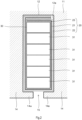
- FIG. 2 is a partially enlarged view of the slot 12 of the stator 10 according to the present embodiment.
- FIG. 2 illustrates one of the plurality of slots 12 illustrated in FIG. 1 as a representative, but configurations of the other slots 12 are the same.
- the slot 12 is a gap formed between the teeth 14 in the stator 10.
- a protrusion portion 14a protruding in a circumferential direction is formed at a tip of the tooth 14, and the slot 12 is opened to the inner peripheral side of the stator 10 from a gap 15 between the protrusion portions 14a.
- the winding wire 30 is inserted into the slot 12, and the insulation sheet 20 is interposed between an inner wall 12a of the slot 12 and the winding wire 30.
- the insulation sheet 20 electrically insulates the stator core 11 and the winding wire 30.
- the insulation sheet 20 is provided with a foamable adhesive on a front surface, and the inner wall 12a of the slot 12 and the winding wire 30 are tightly fixed with each other by foaming of the adhesive by heating.
- the winding wire 30 includes a plurality of rectangular wires 31 each having an insulation film.
- six rectangular wires 31 are accommodated in parallel in a radial direction in one slot 12.
- the number and a shape of the winding wires 30 are not limited thereto.
- thermosetting adhesive is previously coated to both surfaces of the insulation sheet 20 disposed between the slot 12 and the winding wire 30. After assembling the insulation sheet 20 into the inner wall of the slot 12, the winding wire 30 is inserted, the adhesive is melted by heating and then cured, and the inner wall 12a of the slot 12 and the winding wire 30 are brought into close contact with each other.
- the insulation sheet 20 by configuring the insulation sheet 20 as follows, the workability during assembly is improved without lowering the motor efficiency.
- the insulation sheet 20 is disposed to surround the winding wire 30 over an entire periphery of the inner wall 12a of the slot 12.
- a start point and an end point of the insulation sheet 20 are overlapped.
- the insulation sheet 20 includes an insulation paper 21, a first adhesive layer 22 provided on a front surface of the insulation paper 21, and a second adhesive layer 23 provided on a back surface of the insulation paper 21.
- the front surface of the insulation paper 21 is a surface of the insulation sheet 20 on an inner wall 12a side of the slot 12, and the back surface of the insulation paper 21 is a surface of the insulation sheet 20 on a winding wire 30 side.
- the insulation paper 21 is formed in a sheet shape by an insulation material made of paper, non-woven fabric, resin, or the like.
- the first adhesive layer 22 is coated with a foaming adhesive, which foams by heating and is cured after a volume thereof is expanded, in a predetermined thickness.
- the second adhesive layer 23 is coated with a non-foaming adhesive, which is cured by heating without foaming, in a predetermined thickness.
- the foaming adhesive is configured such that, for example, a minute binder that foams by heat is dispersed and mixed in an adhesive, the binder foams when the foaming adhesive is melted by heating, and a volume (thickness) thereof increases.
- the foaming adhesive is cured while maintaining a thickness thereof by further heating.
- the non-foaming adhesive does not contain a foamable material.
- the non-foaming adhesive is melted by heating, and is cured with little change in volume (thickness).
- the non-foaming adhesive is configured such that surface viscosity in an unheated state is lower than that of the foaming adhesive.
- a curing temperature of the non-foaming adhesive is set to be equal to or higher than a curing temperature of the foaming adhesive.
- the foaming adhesive is made of, for example, urethane resin.
- the non-foaming adhesive is made of, for example, epoxy resin.
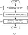
- FIG. 3 is a flowchart illustrating the assembling method of the stator 10 using the insulation sheet 20 according to the present embodiment.
- step S10 the insulation sheet 20 is attached to all the slots 12 of the stator core 11.
- a first front surface of the insulation sheet 20 is brought into close contact with the inner wall 12a of the slot 12 by a jig or the like.
- the front surface of the insulation paper 21 is the first adhesive layer 22 entirely coated with the foaming adhesive having high viscosity, and the insulation sheet 20 can be easily brought into close contact with the inner wall 12a of the slot 12.
- the second adhesive layer 23 on the back surface of the insulation paper 21 is entirely coated with the non-foaming adhesive having low viscosity, the non-foaming adhesive does not adhere to a hand of an operator or the jig during work, and does not interfere with the work.
- step S20 the winding wire 30 is inserted into each slot 12.
- the winding wire 30 includes a plurality of rectangular wires 31 having a U-shape.
- the rectangular wire 31 is inserted in an axial direction of the slot 12 from an open end.
- the inner wall 12a of the slot 12 and the insulation sheet 20 are in close contact with each other by the foaming adhesive having high viscosity.
- the non-foaming adhesive having low viscosity is disposed on the winding wire 30 side, the insulation sheet 20 is less likely to shift when the winding wire 30 is inserted.
- step S30 the insulation sheet 20 attached to the slot 12 is heated to the curing temperature.
- the insulation sheet 20 is kept at the curing temperature for a predetermined time until the foaming adhesive and the non-foaming adhesive are fully cured.
- step S30 first, the foaming adhesive is melted by the temperature rise.
- the foaming adhesive foams by melting to increase the volume thereof. Accordingly, as illustrated in FIG. 4 , the thickness of the foaming adhesive increases, and the void between the inner wall 12a of the slot 12 and the winding wire 30 is filled. Thereafter, the foaming adhesive is cured while maintaining the thickness. At the same time, or after the foaming adhesive is cured, the non-foaming adhesive is melted and cured.
- a thickness of the first adhesive layer is increased by the foaming of the foaming adhesive disposed on the first adhesive layer 22, the void between the inner wall 12a of the slot 12 and the winding wire 30 is filled, and the winding wire 30 is fixed in the slot 12.
- the stator 10 includes the stator core 11 including the slots 12, the winding wires 30 inserted into the slots 12, and the insulation sheets 20 interposed between the slot 12 and the winding wire 30 and electrically insulating the inner wall 12a of the slot 12 and the winding wire 30.
- the insulation sheet 20 includes the insulation paper 21, the first adhesive layer 22 disposed on the front surface of the insulation paper 21 facing the inner wall 12a of the slot 12, and the second adhesive layer 23 disposed on the back surface of the insulation paper 21 facing the winding wire 30.
- the foaming adhesive that is thermally cured while foaming by heating is disposed on the first adhesive layer 22, and the non-foaming adhesive that has lower viscosity than that of a first adhesive when unheated is disposed on the second adhesive layer 23.
- the foaming adhesive is disposed on the front surface facing the inner wall 12a of the slot 12 and the non-foaming adhesive having low viscosity is disposed on the back surface facing the winding wire 30 side, so that insertion resistance of the winding wire 30 when the winding wire 30 is inserted into the slot 12 is reduced, and a reduction in the workability due to shift of the insulation sheet 20 or the like can be suppressed.
- the thickness of the insulation sheet 20 is increased by the foaming of the foaming adhesive by heating and the winding wire 30 and the slot 12 are brought in close contact with each other, so that a decrease in the heat conductivity between the stator core 11 and the winding wire 30 can be suppressed.
- the clearance between the slot 12 and the winding wire 30 can be minimized, and the design of the magnetic circuit including the slot 12 and the winding wire 30 is not restricted. Accordingly, the motor efficiency can be improved.
- the foaming adhesive is disposed on the whole first adhesive layer 22, and the non-foaming adhesive is disposed on the whole second adhesive layer 23.
- the winding wire 30 can be brought into more close contact with the inner wall 12a of the slot 12 by the foaming adhesive.
- the curing temperature of the non-foaming adhesive is equal to or higher (the same or higher) than the curing temperature of the foaming adhesive. According to such a configuration, the foaming adhesive and the non-foaming adhesive are cured after the foaming adhesive foams and the thickness thereof increases, so that the void between the inner wall 12a of the slot 12 and the winding wire 30 is filled, and the winding wire 30 is fixed in the slot 12.
- At least the foaming adhesive is disposed on the surface of the insulation sheet 20 on the inner wall 12a side of the slot 12, and at least the non-foaming adhesive is disposed on the surface of the insulation sheet 20 on the winding wire 30 side, and the following modification may be adopted.
- FIG. 5 is a partially enlarged view of the slot 12 according to a modification of the present embodiment.
- the foaming adhesive is disposed on the first adhesive layer 22 and the second adhesive layer 23 on one surface of two surfaces facing each other in a state where the insulation sheet 20 is disposed in the slot 12.
- the non-foaming adhesive is disposed on the first adhesive layer 22 and the second adhesive layer 23 on the other surface.
- the foaming adhesive is disposed on an entire left side in FIG. 5
- the non-foaming adhesive is disposed on an entire right side in FIG. 5 facing the entire left side.
- the foaming adhesive is disposed on an entire inner side surface of the slot 12 near the gap 15
- the non-foaming adhesive is disposed on an entire outer side surface on a back side in a radial direction of the stator 10. A start point and an end point of the insulation sheet 20 are overlapped near the gap 15 of the slot 12.
- FIG. 6 is a partially enlarged view of the slot 12 according to another modification of the present embodiment.
- the winding wire 30 includes six rectangular wires 31 (31A, 31B, 31C, 31D, 31E, 31F) arranged in a row in the radial direction.
- the foaming adhesive is disposed on the first adhesive layer 22 and the second adhesive layer 23 of the insulation sheet 20 facing one side surface (left side in FIG. 6 ) of the slot 12, and the non-foaming adhesive is disposed on the first adhesive layer 22 and the second adhesive layer 23 of the insulation sheet 20 facing the other side surface (right side in FIG. 6 ).
- the arrangement of the foaming adhesive and the non-foaming adhesive is different from that of the rectangular wire 31A. That is, in the another rectangular wire 31B, the non-foaming adhesive is disposed on the first adhesive layer 22 and the second adhesive layer 23 of the insulation sheet 20 facing the one side surface (left side in FIG. 6 ), and the foaming adhesive is disposed on the first adhesive layer 22 and the second adhesive layer 23 of the insulation sheet 20 facing the other side surface (right side in FIG. 6 ).
- the foaming adhesive and the non-foaming adhesive on the first adhesive layer 22 and the second adhesive layer 23 of the insulation sheet 20 facing each other with the rectangular wire 31 sandwiched therebetween are different, and for the plurality of rectangular wires 31 adjacent in the radial direction, the foaming adhesive and the non-foaming adhesive are disposed alternately in the radial direction.
- the foaming adhesive and the non-foaming adhesive on the first adhesive layer 22 and the second adhesive layer 23 of the insulation sheet 20 facing each other with the plurality of rectangular wires 31 arranged in a row sandwiched therebetween are also disposed alternately.
- the rectangular wires 31 are alternately pressed in directions indicated by outlined arrows in FIG. 6 , moved to a vicinity of the inner wall 12a of the slot 12 and fixed, so that the winding wires 30 and the inner wall 12a of the slot 12 can be reliably brought into close contact with each other through the insulation sheet 20.
- FIG. 7 is a partially enlarged view of the slot 12 according to still another modification of the present embodiment.
- the modification illustrated in FIG. 7 is similar to the modification illustrated in FIG. 6 , a plurality of rectangular wires 31 are set as one group, and an adhesive disposed on the first adhesive layer 22 and the second adhesive layer 23 of the insulation sheet 20 changes for each group.
- the insulation sheet 20 (both sides of the inner wall 12a) at positions facing two rectangular wires 31 on the back side in the radial direction among the rectangular wires 31 of the winding wire 30 is set as a first group 311.
- the insulation sheet 20 (both sides of the inner wall 12a) at positions facing two rectangular wires 31 at positions adjacent to the first group 311 is set as a second group 312.
- the insulation sheet 20 (both sides of the inner wall 12a) at positions facing two rectangular wires 31 on the radially outer side is set as a third group 313.
- the foaming adhesive is disposed on the first adhesive layer 22 and the second adhesive layer 23 of the insulation sheet 20 facing one side surface (left side in FIG. 7 ), and the non-foaming adhesive is disposed on the first adhesive layer 22 and the second adhesive layer 23 of the insulation sheet 20 facing the other side surface (right side in FIG. 7 ).
- the arrangement of the foaming adhesive and the non-foaming adhesive is made different. That is, in the second group 312, the non-foaming adhesive is disposed on the first adhesive layer 22 and the second adhesive layer 23 of the insulation sheet 20 facing the one side surface (left side in FIG. 7 ), and the foaming adhesive is disposed on the first adhesive layer 22 and the second adhesive layer 23 of the insulation sheet 20 facing the other side surface (right side in FIG. 7 ). Similarly, in the third group 313 adjacent to the second group 312, the arrangement of the foaming adhesive and the non-foaming adhesive is made different from that of the second group 312.
- the foaming adhesive and the non-foaming adhesive on the first adhesive layer 22 and the second adhesive layer 23 of the insulation sheet 20 facing each other with the plurality of rectangular wires 31 arranged in a row sandwiched therebetween are also disposed alternatively.
- the rectangular wires 31 arranged in each group are also alternately pressed in directions indicated by outlined arrows in FIG. 7 , moved to a vicinity of the inner wall 12a of the slot 12 and fixed, so that the winding wire 30 and the inner wall 12a of the slot 12 can be reliably brought into close contact with each other through the insulation sheet 20.
- FIG. 8 is a partially enlarged view of the slot 12 according to still another modification of the present embodiment.
- the insulation sheet 20 includes a plurality of insulation sheets (first insulation sheet 20A and second insulation sheet 20B).
- the first insulation sheet 20A in which the foaming adhesive is disposed on the first adhesive layer 22 and the second adhesive layer 23 is inserted.
- the second insulation sheet 20B in which the non-foaming adhesive is disposed on the first adhesive layer 22 and the second adhesive layer 23 is inserted.
- the first insulation sheet 20A and the second insulation sheet 20B are overlapped with each other at a bottom surface on the back side in the radial direction of the slot 12 and the gap 15 on a front side in the radial direction, and in the overlapped portion, the second insulation sheet 20B is disposed on a winding wire 30 side.
- the first insulation sheet 20A on which only the foaming adhesive is disposed and the second insulation sheet 20B on which only the non-foaming adhesive is disposed are configured as separate parts, so that a treatment for forming the first adhesive layer 22 and the second adhesive layer 23 in the insulation sheets 20A and 20B is simplified, and a manufacturing cost of the insulation sheet 20 can be suppressed.
- the winding wire 30 is pressed in a direction indicated by outlined arrows in FIG. 8 , moved to a vicinity of the inner wall 12a of the slot 12 and fixed, so that the winding wire 30 and the inner wall 12a of the slot 12 can be reliably brought into close contact with each other through the insulation sheet 20.
- the first insulation sheet 20A and the second insulation sheet 20B are overlapped with each other at the bottom surface on the back side in the radial direction of the slot 12 and the gap 15 on the front side in the radial direction, but the invention is not limited to the above, the first insulation sheet 20A and the second insulation sheet 20B may be disposed so as to overlap at other positions.
- FIG. 9 is a partially enlarged view of the slot 12 according to yet another modification of the present embodiment
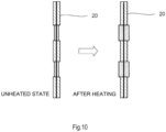
- FIG. 10 is a diagram illustrating the insulation sheet 20 before and after heating.
- a foaming adhesive or a non-foaming adhesive is disposed on each of the first adhesive layer 22 and the second adhesive layer 23 of the insulation sheet 20, and positions thereof are dispersedly (randomly) disposed at positions unrelated to positions of the rectangular wires 31 of the winding wire 30.
- a thickness of a place on the insulation sheet 20 to which the foaming adhesive is coated is smaller when unheated and increased after heating to a curing temperature, as compared with a thickness of a place to which the non-foaming adhesive is coated.
- the thickness of the place on the insulation sheet 20 to which the foaming adhesive is coated is smaller than the thickness of the place to which the non-foaming adhesive is coated. According to the configuration, when the winding wire 30 is inserted (step S20 in FIG. 3 ), since the winding wire 30 does not touch the foaming adhesive on the insulation sheet 20, the winding wire 30 does not adhere to the foaming adhesive, and the insulation sheet 20 fixed to the inner wall 12a of the slot 12 is less likely to shift.
- the winding wire 30 is pressed at the place on which the foaming adhesive is disposed, and the inner wall 12a of the slot 12 and the winding wire 30 can be reliably fixed through the insulation sheet 20.
- FIG. 11 is a partially enlarged view of the slot 12 according to yet another modification of the present embodiment.
- the foaming adhesive and the non-foaming adhesive on the insulation sheet 20 are disposed at positions unrelated to positions of the rectangular wires 31 of the winding wire 30 (randomly). Then, a thickness of a place on the insulation sheet 20 to which the foaming adhesive is coated is smaller when unheated and increased after heating to a curing temperature, as compared with a thickness of a place to which the non-foaming adhesive is coated.
- an adhesive disposed on the first adhesive layer 22 and an adhesive disposed on the second adhesive layer 23 of the insulation sheet 20 at corresponding positions on front and back sides are made different. That is, at a certain place of the insulation sheet 20, the foaming adhesive is disposed on the first adhesive layer 22, and the non-foaming adhesive is disposed on the second adhesive layer 23 on the back side. At another place, the non-foaming adhesive is disposed on the first adhesive layer 22, and the foaming adhesive is disposed on the second adhesive layer 23 on the back side.
- the winding wire 30 when the winding wire 30 is inserted, the winding wire 30 does not touch the foaming adhesive on the insulation sheet 20, so that the winding wire 30 does not adhere to the foaming adhesive either, and the insulation sheet 20 fixed to the inner wall 12a of the slot 12 is less likely to shift.
- the winding wire 30 when a thickness of the foaming adhesive is increased by heating, the winding wire 30 is pressed at the place on which the foaming adhesive is disposed, and the inner wall 12a of the slot 12 and the winding wire 30 can be reliably fixed through the insulation sheet 20.
- FIGS. 12A, 12B, and 12C are diagrams illustrating examples of arrangement of the foaming adhesive and the non-foaming adhesive on the insulation sheet 20 in the modification illustrated in FIG. 11 .
- FIGS. 12A, 12B, and 12C illustrate the first adhesive layer 22 disposed on a front surface of the insulation sheet 20.
- the positions of the foaming adhesive and the non-foaming adhesive are opposite to the arrangement illustrated in FIGS. 12A, 12B, and 12C .
- FIG. 12A illustrates an example in which the foaming adhesive and the non-foaming adhesive are alternately disposed in a belt shape.
- FIG. 12B illustrates an example in which circular foaming adhesives are dispersedly disposed on the non-foaming adhesive.
- FIG. 12C illustrates an example in which the foaming adhesive and the non-foaming adhesive are alternately arranged in a lattice shape.
- the thickness of the place on the insulation sheet 20 to which the foaming adhesive is coated is set smaller than the thickness of the place to which the non-foaming adhesive is coated.
Landscapes
- Engineering & Computer Science (AREA)
- Power Engineering (AREA)
- Manufacturing & Machinery (AREA)
- Insulation, Fastening Of Motor, Generator Windings (AREA)
Abstract
Description
- The present invention relates to a stator of a rotation electrical machine.
- In a rotation electrical machine such as an electric motor, an insulation sheet is used to insulate a stator and a winding wire. An adhesive such as a resinous adhesive that is in close contact with both the stator and the winding wire is disposed on a front surface of the insulation sheet.
-
JP2011-244596A - When foamed resin is used in an insulation sheet as in the related art, resistance when a winding wire is inserted into a slot of a stator is large due to viscosity of the foamed resin, and workability is reduced. If clearance between the slot and the winding wire is increased in order to solve the above, a design of a magnetic circuit including a coil and the stator may be restricted, and heat conductivity between the coil and the stator may also be lowered.
- An object of the invention is to provide a technique capable of improving the workability when inserting the winding wire into the stator without lowering the heat conductivity.
- A stator according to one embodiment of the present is a stator including, a stator core having a slot, a winding wire to be inserted into the slot; and an insulation sheet interposed between the slot and the winding wire and configured to electrically insulate an inner wall of the slot and the winding wire, wherein the insulation sheet includes an insulation paper, a first adhesive layer disposed on a front surface of the insulation paper facing the inner wall of the slot, and a second adhesive layer disposed on a back surface of the insulation paper facing the winding wire, a foaming adhesive to be thermally cured while foaming by heating is disposed on the first adhesive layer, and a non-foaming adhesive having lower viscosity than that of the foaming adhesive when unheated is disposed on the second adhesive layer.
- According to the invention, the foaming adhesive is disposed on a surface of the insulation sheet facing the inner wall of the slot, and the non-foaming adhesive having low viscosity is disposed on a surface facing a winding wire side, so that a reduction in the workability when inserting the winding wire into the slot can be suppressed. After assembling, since the winding wire and the slot are brought into close contact with each other by foaming of the foaming adhesive, a decrease in the heat conductivity between the winding wire and the slot can be suppressed.
-
- [
FIG. 1] FIG. 1 is a diagram illustrating a stator according to an embodiment of the invention. - [
FIG. 2] FIG. 2 is an enlarged view of a slot of the stator. - [
FIG. 3] FIG. 3 is a flowchart of an assembling method of the stator. - [
FIG. 4] FIG. 4 is an enlarged view of a slot of a stator according to a modification. - [
FIG. 5] FIG. 5 is an enlarged view of a slot of a stator according to a modification. - [
FIG. 6] FIG. 6 is an enlarged view of a slot of a stator according to a modification. - [
FIG. 7] FIG. 7 is an enlarged view of a slot of a stator according to a modification. - [
FIG. 8] FIG. 8 is an enlarged view of a slot of a stator according to a modification. - [
FIG. 9] FIG. 9 is an enlarged view of a slot of a stator according to a modification. - [
FIG. 10] FIG. 10 is a diagram illustrating an insulation sheet of a modification. - [
FIG. 11] FIG. 11 is an enlarged view of a slot of a stator according to a modification. - [
FIG. 12A] FIG. 12A is a diagram illustrating an insulation sheet according to the modification. - [
FIG. 12B] FIG. 12B is a diagram illustrating the insulation sheet according to the modification. - [
FIG. 12C] FIG. 12C is a diagram illustrating the insulation sheet according to the modification. - Hereinafter, an embodiment of the invention will be described with reference to the drawings or the like.
-
FIG. 1 is a diagram illustrating astator 10 of a motor (rotation electrical machine) to which an insulation sheet according to the embodiment of the invention is applied when thestator 10 is observed from a rotation axis direction. - The
stator 10 includes astator core 11 in which a plurality ofslots 12 are formed, windingwires 30 inserted into theslots 12, and insulation sheets 20 (seeFIG. 2 ) electrically insulating thestator core 11 and thewinding wires 30. - The
stator core 11 is formed by laminating, in the rotation axis direction, electromagnetic steel sheets punched into a circular ring shape. Thestator core 11 is formed with a circular ring-shaped back yoke 13 and a plurality ofteeth 14 protruding to an inner peripheral side from theback yoke 13. - A void formed between the
teeth 14 constitutes theslot 12, and the winding wire 30 (indicated by hatching inFIG. 1 ) is inserted into theslot 12. - A rotor (not illustrated) is disposed on an inner peripheral side of the
stator 10. By passing a current through thewinding wires 30 of thestator 10, the rotor rotates due to interaction with permanent magnets provided on the rotor. - Although an example is illustrated in which 48
slots 12 are formed in thestator core 11 illustrated inFIG. 1 , the number of theslots 12 is not limited to 48. - The motor according to the present embodiment is mounted on, for example, an electric vehicle and functions as an electric motor that drives wheels. In addition, the motor functions as a generator that performs power generation (regeneration) by receiving a driving force generated by the rotation of the wheels. The motor may be used as a device other than the vehicle, for example, one of driving devices of various electric devices or industrial machines.
- Next, a configuration of the
slot 12 of thestator 10 will be described. -
FIG. 2 is a partially enlarged view of theslot 12 of thestator 10 according to the present embodiment.FIG. 2 illustrates one of the plurality ofslots 12 illustrated inFIG. 1 as a representative, but configurations of theother slots 12 are the same. - The
slot 12 is a gap formed between theteeth 14 in thestator 10. Aprotrusion portion 14a protruding in a circumferential direction is formed at a tip of thetooth 14, and theslot 12 is opened to the inner peripheral side of thestator 10 from agap 15 between theprotrusion portions 14a. - The winding
wire 30 is inserted into theslot 12, and theinsulation sheet 20 is interposed between aninner wall 12a of theslot 12 and the windingwire 30. - The
insulation sheet 20 electrically insulates thestator core 11 and the windingwire 30. Theinsulation sheet 20 is provided with a foamable adhesive on a front surface, and theinner wall 12a of theslot 12 and the windingwire 30 are tightly fixed with each other by foaming of the adhesive by heating. - The
winding wire 30 includes a plurality ofrectangular wires 31 each having an insulation film. In the example illustrated inFIG. 2 , sixrectangular wires 31 are accommodated in parallel in a radial direction in oneslot 12. The number and a shape of the windingwires 30 are not limited thereto. - Next, a configuration of the
insulation sheet 20 will be described. - In the related art, a thermosetting adhesive is previously coated to both surfaces of the
insulation sheet 20 disposed between theslot 12 and the windingwire 30. After assembling theinsulation sheet 20 into the inner wall of theslot 12, thewinding wire 30 is inserted, the adhesive is melted by heating and then cured, and theinner wall 12a of theslot 12 and the windingwire 30 are brought into close contact with each other. - Here, when a foaming adhesive whose volume expands due to heat is used such that the
slot 12 and thewinding wire 30 are brought into close contact with each other, since a surface tackiness is larger than that of a non-foaming adhesive, in a process of assembling theinsulation sheet 20 into theslot 12 or in a process of inserting thewinding wire 30 into the slot, theinsulation sheet 20 may be adhered and workability may be reduced. - If clearance between the inner wall of the
slot 12 and the windingwire 30 is increased in order to prevent the above, a distance between the inner wall of theslot 12 and the windingwire 30 is increased, and a design of a magnetic circuit formed by thestator core 11 and the windingwire 30 is restricted. In addition, since heat conductivity from the windingwire 30 to thestator 10 is lowered, a heat treatment is restricted, and as a result, motor efficiency is lowered. - Therefore, in the present embodiment, by configuring the
insulation sheet 20 as follows, the workability during assembly is improved without lowering the motor efficiency. - As illustrated in
FIG. 2 , theinsulation sheet 20 is disposed to surround the windingwire 30 over an entire periphery of theinner wall 12a of theslot 12. In a bottom portion located on a radially outer side of theslot 12, a start point and an end point of theinsulation sheet 20 are overlapped. - The
insulation sheet 20 includes aninsulation paper 21, a firstadhesive layer 22 provided on a front surface of theinsulation paper 21, and a secondadhesive layer 23 provided on a back surface of theinsulation paper 21. The front surface of theinsulation paper 21 is a surface of theinsulation sheet 20 on aninner wall 12a side of theslot 12, and the back surface of theinsulation paper 21 is a surface of theinsulation sheet 20 on a windingwire 30 side. - The
insulation paper 21 is formed in a sheet shape by an insulation material made of paper, non-woven fabric, resin, or the like. - The first
adhesive layer 22 is coated with a foaming adhesive, which foams by heating and is cured after a volume thereof is expanded, in a predetermined thickness. The secondadhesive layer 23 is coated with a non-foaming adhesive, which is cured by heating without foaming, in a predetermined thickness. - The foaming adhesive is configured such that, for example, a minute binder that foams by heat is dispersed and mixed in an adhesive, the binder foams when the foaming adhesive is melted by heating, and a volume (thickness) thereof increases. The foaming adhesive is cured while maintaining a thickness thereof by further heating.
- The non-foaming adhesive does not contain a foamable material. The non-foaming adhesive is melted by heating, and is cured with little change in volume (thickness). The non-foaming adhesive is configured such that surface viscosity in an unheated state is lower than that of the foaming adhesive.
- A curing temperature of the non-foaming adhesive is set to be equal to or higher than a curing temperature of the foaming adhesive. The foaming adhesive is made of, for example, urethane resin. The non-foaming adhesive is made of, for example, epoxy resin.
- Next, an assembling method of the
stator 10 configured as described above will be described. -
FIG. 3 is a flowchart illustrating the assembling method of thestator 10 using theinsulation sheet 20 according to the present embodiment. - First, in step S10, the
insulation sheet 20 is attached to all theslots 12 of thestator core 11. For example, a first front surface of theinsulation sheet 20 is brought into close contact with theinner wall 12a of theslot 12 by a jig or the like. - The front surface of the
insulation paper 21 is the firstadhesive layer 22 entirely coated with the foaming adhesive having high viscosity, and theinsulation sheet 20 can be easily brought into close contact with theinner wall 12a of theslot 12. In addition, since the secondadhesive layer 23 on the back surface of theinsulation paper 21 is entirely coated with the non-foaming adhesive having low viscosity, the non-foaming adhesive does not adhere to a hand of an operator or the jig during work, and does not interfere with the work. - Next, in step S20, the winding
wire 30 is inserted into eachslot 12. - The winding
wire 30 includes a plurality ofrectangular wires 31 having a U-shape. Therectangular wire 31 is inserted in an axial direction of theslot 12 from an open end. At this time, theinner wall 12a of theslot 12 and theinsulation sheet 20 are in close contact with each other by the foaming adhesive having high viscosity. In addition, since the non-foaming adhesive having low viscosity is disposed on the windingwire 30 side, theinsulation sheet 20 is less likely to shift when the windingwire 30 is inserted. - Next, in step S30, the
insulation sheet 20 attached to theslot 12 is heated to the curing temperature. - For example, after putting the
entire stator 10 into a furnace and heating theinsulation sheet 20 to the curing temperature, theinsulation sheet 20 is kept at the curing temperature for a predetermined time until the foaming adhesive and the non-foaming adhesive are fully cured. - In the process in step S30, first, the foaming adhesive is melted by the temperature rise. The foaming adhesive foams by melting to increase the volume thereof. Accordingly, as illustrated in
FIG. 4 , the thickness of the foaming adhesive increases, and the void between theinner wall 12a of theslot 12 and the windingwire 30 is filled. Thereafter, the foaming adhesive is cured while maintaining the thickness. At the same time, or after the foaming adhesive is cured, the non-foaming adhesive is melted and cured. - According to such a treatment, a thickness of the first adhesive layer is increased by the foaming of the foaming adhesive disposed on the first
adhesive layer 22, the void between theinner wall 12a of theslot 12 and the windingwire 30 is filled, and the windingwire 30 is fixed in theslot 12. - As described above, the
stator 10 according to the present embodiment includes thestator core 11 including theslots 12, the windingwires 30 inserted into theslots 12, and theinsulation sheets 20 interposed between theslot 12 and the windingwire 30 and electrically insulating theinner wall 12a of theslot 12 and the windingwire 30. Theinsulation sheet 20 includes theinsulation paper 21, the firstadhesive layer 22 disposed on the front surface of theinsulation paper 21 facing theinner wall 12a of theslot 12, and the secondadhesive layer 23 disposed on the back surface of theinsulation paper 21 facing the windingwire 30. The foaming adhesive that is thermally cured while foaming by heating is disposed on the firstadhesive layer 22, and the non-foaming adhesive that has lower viscosity than that of a first adhesive when unheated is disposed on the secondadhesive layer 23. - According to such a configuration, in the
insulation sheet 20, the foaming adhesive is disposed on the front surface facing theinner wall 12a of theslot 12 and the non-foaming adhesive having low viscosity is disposed on the back surface facing the windingwire 30 side, so that insertion resistance of the windingwire 30 when the windingwire 30 is inserted into theslot 12 is reduced, and a reduction in the workability due to shift of theinsulation sheet 20 or the like can be suppressed. In addition, after the assembling, the thickness of theinsulation sheet 20 is increased by the foaming of the foaming adhesive by heating and the windingwire 30 and theslot 12 are brought in close contact with each other, so that a decrease in the heat conductivity between thestator core 11 and the windingwire 30 can be suppressed. Further, the clearance between theslot 12 and the windingwire 30 can be minimized, and the design of the magnetic circuit including theslot 12 and the windingwire 30 is not restricted. Accordingly, the motor efficiency can be improved. - In the present embodiment, in the
insulation sheet 20, the foaming adhesive is disposed on the whole firstadhesive layer 22, and the non-foaming adhesive is disposed on the whole secondadhesive layer 23. - According to such a configuration, by disposing the
insulation sheet 20 around the windingwire 30, the windingwire 30 can be brought into more close contact with theinner wall 12a of theslot 12 by the foaming adhesive. - In the present embodiment, the curing temperature of the non-foaming adhesive is equal to or higher (the same or higher) than the curing temperature of the foaming adhesive. According to such a configuration, the foaming adhesive and the non-foaming adhesive are cured after the foaming adhesive foams and the thickness thereof increases, so that the void between the
inner wall 12a of theslot 12 and the windingwire 30 is filled, and the windingwire 30 is fixed in theslot 12. - Next, modifications of the present embodiment will be described.
- As described above, in the present embodiment, it is sufficient that at least the foaming adhesive is disposed on the surface of the
insulation sheet 20 on theinner wall 12a side of theslot 12, and at least the non-foaming adhesive is disposed on the surface of theinsulation sheet 20 on the windingwire 30 side, and the following modification may be adopted. -
FIG. 5 is a partially enlarged view of theslot 12 according to a modification of the present embodiment. - In an example illustrated in
FIG. 5 , the foaming adhesive is disposed on the firstadhesive layer 22 and the secondadhesive layer 23 on one surface of two surfaces facing each other in a state where theinsulation sheet 20 is disposed in theslot 12. The non-foaming adhesive is disposed on the firstadhesive layer 22 and the secondadhesive layer 23 on the other surface. - More specifically, in the
inner wall 12a of theslot 12, the foaming adhesive is disposed on an entire left side inFIG. 5 , and the non-foaming adhesive is disposed on an entire right side inFIG. 5 facing the entire left side. In addition, in theinner wall 12a of theslot 12, the foaming adhesive is disposed on an entire inner side surface of theslot 12 near thegap 15, and the non-foaming adhesive is disposed on an entire outer side surface on a back side in a radial direction of thestator 10. A start point and an end point of theinsulation sheet 20 are overlapped near thegap 15 of theslot 12. - When such a stator is heated, a thickness of the foaming adhesive increases, the winding
wire 30 is pressed in directions indicated by outlined arrows inFIG. 5 , moved to a vicinity of theinner wall 12a of theslot 12 and fixed, so that the windingwire 30 and theinner wall 12a of theslot 12 can be reliably brought into close contact with each other through theinsulation sheet 20. -
FIG. 6 is a partially enlarged view of theslot 12 according to another modification of the present embodiment. - In an example illustrated in
FIG. 6 , for each of therectangular wires 31 that constitute the windingwire 30, adhesives disposed on the firstadhesive layer 22 and the secondadhesive layer 23 of theinsulation sheet 20 facing each other with therectangular wire 31 sandwiched therebetween are different from each other. - In
FIG. 6 , the windingwire 30 includes six rectangular wires 31 (31A, 31B, 31C, 31D, 31E, 31F) arranged in a row in the radial direction. - In the
rectangular wire 31A among therectangular wires 31, the foaming adhesive is disposed on the firstadhesive layer 22 and the secondadhesive layer 23 of theinsulation sheet 20 facing one side surface (left side inFIG. 6 ) of theslot 12, and the non-foaming adhesive is disposed on the firstadhesive layer 22 and the secondadhesive layer 23 of theinsulation sheet 20 facing the other side surface (right side inFIG. 6 ). - In another
rectangular wire 31B adjacent to therectangular wire 31A in the radial direction, the arrangement of the foaming adhesive and the non-foaming adhesive is different from that of therectangular wire 31A. That is, in the anotherrectangular wire 31B, the non-foaming adhesive is disposed on the firstadhesive layer 22 and the secondadhesive layer 23 of theinsulation sheet 20 facing the one side surface (left side inFIG. 6 ), and the foaming adhesive is disposed on the firstadhesive layer 22 and the secondadhesive layer 23 of theinsulation sheet 20 facing the other side surface (right side inFIG. 6 ). - In this way, for each of the
rectangular wires 31, the foaming adhesive and the non-foaming adhesive on the firstadhesive layer 22 and the secondadhesive layer 23 of theinsulation sheet 20 facing each other with therectangular wire 31 sandwiched therebetween are different, and for the plurality ofrectangular wires 31 adjacent in the radial direction, the foaming adhesive and the non-foaming adhesive are disposed alternately in the radial direction. In addition, in the radial direction of theslot 12, the foaming adhesive and the non-foaming adhesive on the firstadhesive layer 22 and the secondadhesive layer 23 of theinsulation sheet 20 facing each other with the plurality ofrectangular wires 31 arranged in a row sandwiched therebetween are also disposed alternately. - According to such a configuration, when a thickness of the foaming adhesive is increased by heating, the
rectangular wires 31 are alternately pressed in directions indicated by outlined arrows inFIG. 6 , moved to a vicinity of theinner wall 12a of theslot 12 and fixed, so that the windingwires 30 and theinner wall 12a of theslot 12 can be reliably brought into close contact with each other through theinsulation sheet 20. -
FIG. 7 is a partially enlarged view of theslot 12 according to still another modification of the present embodiment. - The modification illustrated in
FIG. 7 is similar to the modification illustrated inFIG. 6 , a plurality ofrectangular wires 31 are set as one group, and an adhesive disposed on the firstadhesive layer 22 and the secondadhesive layer 23 of theinsulation sheet 20 changes for each group. - As illustrated in
FIG. 7 , the insulation sheet 20 (both sides of theinner wall 12a) at positions facing tworectangular wires 31 on the back side in the radial direction among therectangular wires 31 of the windingwire 30 is set as afirst group 311. Similarly, the insulation sheet 20 (both sides of theinner wall 12a) at positions facing tworectangular wires 31 at positions adjacent to thefirst group 311 is set as asecond group 312. Similarly, the insulation sheet 20 (both sides of theinner wall 12a) at positions facing tworectangular wires 31 on the radially outer side is set as athird group 313. - In the
first group 311, the foaming adhesive is disposed on the firstadhesive layer 22 and the secondadhesive layer 23 of theinsulation sheet 20 facing one side surface (left side inFIG. 7 ), and the non-foaming adhesive is disposed on the firstadhesive layer 22 and the secondadhesive layer 23 of theinsulation sheet 20 facing the other side surface (right side inFIG. 7 ). - In the
second group 312 adjacent to thefirst group 311, the arrangement of the foaming adhesive and the non-foaming adhesive is made different. That is, in thesecond group 312, the non-foaming adhesive is disposed on the firstadhesive layer 22 and the secondadhesive layer 23 of theinsulation sheet 20 facing the one side surface (left side inFIG. 7 ), and the foaming adhesive is disposed on the firstadhesive layer 22 and the secondadhesive layer 23 of theinsulation sheet 20 facing the other side surface (right side inFIG. 7 ). Similarly, in thethird group 313 adjacent to thesecond group 312, the arrangement of the foaming adhesive and the non-foaming adhesive is made different from that of thesecond group 312. In addition, in the radial direction of theslot 12, the foaming adhesive and the non-foaming adhesive on the firstadhesive layer 22 and the secondadhesive layer 23 of theinsulation sheet 20 facing each other with the plurality ofrectangular wires 31 arranged in a row sandwiched therebetween are also disposed alternatively. - In such a configuration, when a thickness of the foaming adhesive is increased by heating, the
rectangular wires 31 arranged in each group are also alternately pressed in directions indicated by outlined arrows inFIG. 7 , moved to a vicinity of theinner wall 12a of theslot 12 and fixed, so that the windingwire 30 and theinner wall 12a of theslot 12 can be reliably brought into close contact with each other through theinsulation sheet 20. -
FIG. 8 is a partially enlarged view of theslot 12 according to still another modification of the present embodiment. - In the modification illustrated in
FIG. 8 , theinsulation sheet 20 includes a plurality of insulation sheets (first insulation sheet 20A andsecond insulation sheet 20B). - As illustrated in
FIG. 8 , on one side surface (left side inFIG. 8 ) of theslot 12, thefirst insulation sheet 20A in which the foaming adhesive is disposed on the firstadhesive layer 22 and the secondadhesive layer 23 is inserted. On the other side surface (right side inFIG. 8 ) of theslot 12, thesecond insulation sheet 20B in which the non-foaming adhesive is disposed on the firstadhesive layer 22 and the secondadhesive layer 23 is inserted. - The
first insulation sheet 20A and thesecond insulation sheet 20B are overlapped with each other at a bottom surface on the back side in the radial direction of theslot 12 and thegap 15 on a front side in the radial direction, and in the overlapped portion, thesecond insulation sheet 20B is disposed on a windingwire 30 side. - In such a configuration, in particular, the
first insulation sheet 20A on which only the foaming adhesive is disposed and thesecond insulation sheet 20B on which only the non-foaming adhesive is disposed are configured as separate parts, so that a treatment for forming the firstadhesive layer 22 and the secondadhesive layer 23 in theinsulation sheets insulation sheet 20 can be suppressed. - Further, as in the modification illustrated in
FIG. 5 described above, when a thickness of the foaming adhesive of thefirst insulation sheet 20A is increased by heating, the windingwire 30 is pressed in a direction indicated by outlined arrows inFIG. 8 , moved to a vicinity of theinner wall 12a of theslot 12 and fixed, so that the windingwire 30 and theinner wall 12a of theslot 12 can be reliably brought into close contact with each other through theinsulation sheet 20. - In the modification illustrated in
FIG. 8 , thefirst insulation sheet 20A and thesecond insulation sheet 20B are overlapped with each other at the bottom surface on the back side in the radial direction of theslot 12 and thegap 15 on the front side in the radial direction, but the invention is not limited to the above, thefirst insulation sheet 20A and thesecond insulation sheet 20B may be disposed so as to overlap at other positions. -
FIG. 9 is a partially enlarged view of theslot 12 according to yet another modification of the present embodiment, andFIG. 10 is a diagram illustrating theinsulation sheet 20 before and after heating. - In the modification illustrated in
FIG. 9 , as in the modification illustrated inFIG. 7 , a foaming adhesive or a non-foaming adhesive is disposed on each of the firstadhesive layer 22 and the secondadhesive layer 23 of theinsulation sheet 20, and positions thereof are dispersedly (randomly) disposed at positions unrelated to positions of therectangular wires 31 of the windingwire 30. - Further, a thickness of a place on the
insulation sheet 20 to which the foaming adhesive is coated is smaller when unheated and increased after heating to a curing temperature, as compared with a thickness of a place to which the non-foaming adhesive is coated. - As illustrated in
FIG. 10 , when not heated, the thickness of the place on theinsulation sheet 20 to which the foaming adhesive is coated is smaller than the thickness of the place to which the non-foaming adhesive is coated. According to the configuration, when the windingwire 30 is inserted (step S20 inFIG. 3 ), since the windingwire 30 does not touch the foaming adhesive on theinsulation sheet 20, the windingwire 30 does not adhere to the foaming adhesive, and theinsulation sheet 20 fixed to theinner wall 12a of theslot 12 is less likely to shift. - Further, when a thickness of the foaming adhesive is increased by heating, the winding
wire 30 is pressed at the place on which the foaming adhesive is disposed, and theinner wall 12a of theslot 12 and the windingwire 30 can be reliably fixed through theinsulation sheet 20. -
FIG. 11 is a partially enlarged view of theslot 12 according to yet another modification of the present embodiment. - In the modification illustrated in
FIG. 11 , as in the modification illustrated inFIG. 9 , the foaming adhesive and the non-foaming adhesive on theinsulation sheet 20 are disposed at positions unrelated to positions of therectangular wires 31 of the winding wire 30 (randomly). Then, a thickness of a place on theinsulation sheet 20 to which the foaming adhesive is coated is smaller when unheated and increased after heating to a curing temperature, as compared with a thickness of a place to which the non-foaming adhesive is coated. - Further, an adhesive disposed on the first
adhesive layer 22 and an adhesive disposed on the secondadhesive layer 23 of theinsulation sheet 20 at corresponding positions on front and back sides are made different. That is, at a certain place of theinsulation sheet 20, the foaming adhesive is disposed on the firstadhesive layer 22, and the non-foaming adhesive is disposed on the secondadhesive layer 23 on the back side. At another place, the non-foaming adhesive is disposed on the firstadhesive layer 22, and the foaming adhesive is disposed on the secondadhesive layer 23 on the back side. - According to such a configuration, as in the modification illustrated in
FIG. 9 , when the windingwire 30 is inserted, the windingwire 30 does not touch the foaming adhesive on theinsulation sheet 20, so that the windingwire 30 does not adhere to the foaming adhesive either, and theinsulation sheet 20 fixed to theinner wall 12a of theslot 12 is less likely to shift. In addition, when a thickness of the foaming adhesive is increased by heating, the windingwire 30 is pressed at the place on which the foaming adhesive is disposed, and theinner wall 12a of theslot 12 and the windingwire 30 can be reliably fixed through theinsulation sheet 20. -
FIGS. 12A, 12B, and 12C are diagrams illustrating examples of arrangement of the foaming adhesive and the non-foaming adhesive on theinsulation sheet 20 in the modification illustrated inFIG. 11 . -
FIGS. 12A, 12B, and 12C illustrate the firstadhesive layer 22 disposed on a front surface of theinsulation sheet 20. In the secondadhesive layer 23 disposed on a back surface of theinsulation sheet 20, the positions of the foaming adhesive and the non-foaming adhesive are opposite to the arrangement illustrated inFIGS. 12A, 12B, and 12C . -
FIG. 12A illustrates an example in which the foaming adhesive and the non-foaming adhesive are alternately disposed in a belt shape. -
FIG. 12B illustrates an example in which circular foaming adhesives are dispersedly disposed on the non-foaming adhesive. -
FIG. 12C illustrates an example in which the foaming adhesive and the non-foaming adhesive are alternately arranged in a lattice shape. - In any case, the thickness of the place on the
insulation sheet 20 to which the foaming adhesive is coated is set smaller than the thickness of the place to which the non-foaming adhesive is coated. - In this way, by disposing the foaming adhesive and the non-foaming adhesive on the
insulation sheet 20, a degree of freedom in forming the firstadhesive layer 22 and the secondadhesive layer 23 on theinsulation sheet 20 increases, and a manufacturing cost of theinsulation sheet 20 can be suppressed. - Although the embodiment and the modifications of the invention have been described above, the above embodiment and modifications are merely a part of application examples of the invention, and do not mean that the technical scope of the invention is limited to the specific configurations of the above embodiment. The embodiment described above has been described as a single embodiment, but may be appropriately combined.
Claims (8)
- A stator comprising:a stator core having a slot;a winding wire to be inserted into the slot; andan insulation sheet interposed between the slot and the winding wire and configured to electrically insulate an inner wall of the slot and the winding wire, whereinthe insulation sheet includes an insulation paper, a first adhesive layer disposed on a front surface of the insulation paper facing the inner wall of the slot, and a second adhesive layer disposed on a back surface of the insulation paper facing the winding wire,a foaming adhesive to be thermally cured while foaming by heating is disposed on the first adhesive layer, anda non-foaming adhesive having lower viscosity than that of the foaming adhesive when unheated is disposed on the second adhesive layer.
- The stator according to claim 1, wherein
in the insulation sheet, the foaming adhesive is disposed on the first adhesive layer entirely, and the non-foaming adhesive is disposed on a second adhesive layer entirely. - The stator according to claim 1, wherein
in the insulation sheet, among two surfaces facing each other in the slot, the foaming adhesive is disposed on the first adhesive layer and the second adhesive layer on one surface, and the non-foaming adhesive is disposed on the first adhesive layer and the second adhesive layer on the other surface. - The stator according to claim 3, whereinthe winding wire includes a plurality of rectangular wires arranged in a row in a radial direction of the stator in the slot, andin the insulation sheet, in at least one of the plurality of rectangular wires, the foaming adhesive and the non-foaming adhesive are respectively disposed on the first adhesive layer and the second adhesive layer facing each other with the one rectangular wire sandwiched therebetween, and the arrangement of the foaming adhesive and the non-foaming adhesive is different from that of another rectangular wire adjacent to the one rectangular wire in the radial direction.
- The stator according to claim 1, whereinthe insulation sheet includes a first insulation sheet in contact with one side surface of the inner wall of the slot, and a second insulation sheet in contact with the other side surface of the inner wall of the slot, in the inner wall of the slot, andthe foaming adhesive is disposed on the first adhesive layer and the second adhesive layer of the first insulation sheet, and the non-foaming adhesive is disposed on the first adhesive layer and the second adhesive layer of the second insulation sheet.
- The stator according to claim 1, wherein
in the insulation sheet, the foaming adhesive and the non-foaming adhesive are dispersedly disposed on the first adhesive layer and the second adhesive layer. - The stator according to claim 6, wherein
the insulation sheet is formed such that, when unheated, a thickness of a place on which the foaming adhesive is disposed is smaller than a thickness of a place on which the non-foaming adhesive is disposed. - The stator according to any one of claims 1 to 7, wherein
a curing temperature of the non-foaming adhesive is equal to or higher than a curing temperature of the foaming adhesive.
Applications Claiming Priority (1)
| Application Number | Priority Date | Filing Date | Title |
|---|---|---|---|
| PCT/JP2021/014400 WO2022208892A1 (en) | 2021-04-02 | 2021-04-02 | Stator |
Publications (3)
| Publication Number | Publication Date |
|---|---|
| EP4318891A1 true EP4318891A1 (en) | 2024-02-07 |
| EP4318891A4 EP4318891A4 (en) | 2024-05-15 |
| EP4318891B1 EP4318891B1 (en) | 2025-11-12 |
Family
ID=83457567
Family Applications (1)
| Application Number | Title | Priority Date | Filing Date |
|---|---|---|---|
| EP21933498.4A Active EP4318891B1 (en) | 2021-04-02 | 2021-04-02 | Stator |
Country Status (5)
| Country | Link |
|---|---|
| US (1) | US12494689B2 (en) |
| EP (1) | EP4318891B1 (en) |
| JP (1) | JP7537603B2 (en) |
| CN (1) | CN117044076A (en) |
| WO (1) | WO2022208892A1 (en) |
Cited By (1)
| Publication number | Priority date | Publication date | Assignee | Title |
|---|---|---|---|---|
| EP4625772A1 (en) * | 2024-03-25 | 2025-10-01 | Aisin Corporation | Rotary electric machine |
Families Citing this family (2)
| Publication number | Priority date | Publication date | Assignee | Title |
|---|---|---|---|---|
| JP2024065298A (en) * | 2022-10-31 | 2024-05-15 | 株式会社日立製作所 | Rotating electrical machinery and industrial machinery |
| EP4391319A1 (en) * | 2022-12-22 | 2024-06-26 | Valeo eAutomotive Germany GmbH | Method for producing a stator for an electric rotating machine, stator, electric rotating machine and vehicle |
Family Cites Families (39)
| Publication number | Priority date | Publication date | Assignee | Title |
|---|---|---|---|---|
| US20050134137A1 (en) * | 2003-12-17 | 2005-06-23 | Sweo Edwin A. | Method for manufacturing squirrel cage rotor |
| JP4504143B2 (en) * | 2004-09-22 | 2010-07-14 | 株式会社東芝 | Fixing method of stator coil of rotating electric machine |
| JP2010259316A (en) * | 2009-03-31 | 2010-11-11 | Denso Corp | Stator for rotating electric machine and method for manufacturing the same |
| JP5497532B2 (en) | 2010-05-18 | 2014-05-21 | トヨタ自動車株式会社 | Method for manufacturing stator of electric motor |
| JP5981089B2 (en) * | 2010-08-23 | 2016-08-31 | トヨタ自動車株式会社 | Insulating resin sheet for fixing coil, stator for motor using insulating resin sheet for fixing coil, and method for manufacturing stator for motor |
| JP5331160B2 (en) * | 2011-05-18 | 2013-10-30 | トヨタ自動車株式会社 | Coil fixing member of rotating electric machine and rotating electric machine |
| JP5833844B2 (en) * | 2011-06-24 | 2015-12-16 | トヨタ自動車株式会社 | Insulating member for rotating electrical machine, stator for rotating electrical machine, and method for manufacturing stator for rotating electrical machine |
| US20130069474A1 (en) * | 2011-09-16 | 2013-03-21 | Remy Technologies, L.L.C. | Composite conductor insulation |
| US20130125396A1 (en) * | 2011-11-18 | 2013-05-23 | Remy Technologies, L.L.C. | Wrapped wire for electric machine |
| JP5718854B2 (en) * | 2012-05-09 | 2015-05-13 | トヨタ自動車株式会社 | Inflatable sheet for rotating electrical machine, stator for rotating electrical machine using the expanded sheet for rotating electrical machine, and method for manufacturing stator for rotating electrical machine |
| CA2893045A1 (en) * | 2013-02-07 | 2014-08-14 | Furukawa Electric Co., Ltd. | Insulated wire and motor |
| JP6307876B2 (en) * | 2013-12-26 | 2018-04-11 | トヨタ自動車株式会社 | Stator and stator manufacturing method |
| JP6350107B2 (en) * | 2014-08-21 | 2018-07-04 | トヨタ自動車株式会社 | Insulator for stator, stator for rotating electrical machine using the same, and method for manufacturing stator for rotating electrical machine |
| EP3073615A1 (en) * | 2015-03-26 | 2016-09-28 | Siemens Aktiengesellschaft | Self-adhesive groove closure device for an electric machine |
| ES2896801T3 (en) * | 2015-04-10 | 2022-02-25 | Teraoka Seisakusho Kk | adhesive foil |
| JP6685878B2 (en) * | 2016-10-14 | 2020-04-22 | 本田技研工業株式会社 | Rotating electric machine and method of manufacturing rotating electric machine |
| JP2018078764A (en) * | 2016-11-11 | 2018-05-17 | トヨタ自動車株式会社 | Motor stator |
| WO2018131703A1 (en) * | 2017-01-16 | 2018-07-19 | 本田技研工業株式会社 | Insulating member, stator of rotary electric machine, and rotary electric machine |
| JP6959778B2 (en) * | 2017-07-13 | 2021-11-05 | 株式会社デンソー | Stator of rotary electric machine and manufacturing method of the stator |
| WO2019168100A1 (en) * | 2018-03-01 | 2019-09-06 | アイシン・エィ・ダブリュ株式会社 | Armature manufacturing method and armature |
| JP7043294B2 (en) * | 2018-03-07 | 2022-03-29 | 本田技研工業株式会社 | Rotating electric machine |
| JP2019161951A (en) * | 2018-03-15 | 2019-09-19 | 本田技研工業株式会社 | Rotating electrical machine stator |
| JP6996617B2 (en) * | 2018-03-26 | 2022-01-17 | 株式会社アイシン | Manufacturing method of stator for rotary electric machine and stator for rotary electric machine |
| WO2020026707A1 (en) * | 2018-07-31 | 2020-02-06 | アイシン・エィ・ダブリュ株式会社 | Armature |
| JP7151771B2 (en) * | 2018-07-31 | 2022-10-12 | 株式会社アイシン | Armature |
| CN112840529A (en) * | 2018-10-03 | 2021-05-25 | 日立安斯泰莫株式会社 | Rotary motor |
| JP7040428B2 (en) * | 2018-12-03 | 2022-03-23 | トヨタ自動車株式会社 | Stator |
| TWI725670B (en) * | 2018-12-17 | 2021-04-21 | 日商日本製鐵股份有限公司 | Laminated iron core, its manufacturing method and rotating electric machine |
| JP2020167797A (en) * | 2019-03-28 | 2020-10-08 | アイシン・エィ・ダブリュ株式会社 | How to manufacture the stator and the stator |
| JP2021083240A (en) * | 2019-11-20 | 2021-05-27 | 株式会社デンソー | Rotary electric machine |
| US12466143B2 (en) * | 2019-12-02 | 2025-11-11 | Hokuriku Color Foam Co., Ltd. | Method for manufacturing fiber-reinforced resin structure |
| JP7493347B2 (en) * | 2020-02-12 | 2024-05-31 | スリーエム イノベイティブ プロパティズ カンパニー | Heat-expandable and heat-curable adhesive sheet |
| RS66670B1 (en) * | 2020-06-17 | 2025-05-30 | Nippon Steel Corp | Electrical steel sheet, laminated core and rotating electric machine |
| EP4169713A4 (en) * | 2020-06-17 | 2023-12-13 | Nippon Steel Corporation | Coating composition for electromagnetic steel sheets, surface-coated electromagnetic steel sheet for adhesion, and laminated iron core |
| US12502876B2 (en) * | 2020-09-24 | 2025-12-23 | Toray Industries, Inc. | Laminate |
| EP4488344A4 (en) * | 2022-03-01 | 2025-12-03 | Dainippon Printing Co Ltd | FOAMING ADHESIVE FILM AND MANUFACTURING PROCESS FOR ARTICLES |
| JP2024004255A (en) * | 2022-06-28 | 2024-01-16 | 日立Astemo電動機システムズ株式会社 | Stator of rotating electric machine |
| JP7591596B2 (en) * | 2023-03-06 | 2024-11-28 | 本田技研工業株式会社 | Rotating electric machine and insulating member |
| EP4509316A1 (en) * | 2023-08-08 | 2025-02-19 | Bestway Inflatables & Material Corp. | A sheet manufacturing apparatus and sheet manufacturing method for a sheet of an inflatable product |
-
2021
- 2021-04-02 WO PCT/JP2021/014400 patent/WO2022208892A1/en not_active Ceased
- 2021-04-02 US US18/284,259 patent/US12494689B2/en active Active
- 2021-04-02 JP JP2023510157A patent/JP7537603B2/en active Active
- 2021-04-02 CN CN202180096195.2A patent/CN117044076A/en active Pending
- 2021-04-02 EP EP21933498.4A patent/EP4318891B1/en active Active
Cited By (1)
| Publication number | Priority date | Publication date | Assignee | Title |
|---|---|---|---|---|
| EP4625772A1 (en) * | 2024-03-25 | 2025-10-01 | Aisin Corporation | Rotary electric machine |
Also Published As
| Publication number | Publication date |
|---|---|
| US20240154485A1 (en) | 2024-05-09 |
| CN117044076A (en) | 2023-11-10 |
| JPWO2022208892A1 (en) | 2022-10-06 |
| JP7537603B2 (en) | 2024-08-21 |
| US12494689B2 (en) | 2025-12-09 |
| EP4318891A4 (en) | 2024-05-15 |
| WO2022208892A1 (en) | 2022-10-06 |
| EP4318891B1 (en) | 2025-11-12 |
Similar Documents
| Publication | Publication Date | Title |
|---|---|---|
| CN113258704B (en) | Coil frame, stator core and distributed winding radial gap type rotating motor | |
| EP4318891B1 (en) | Stator | |
| JP5833844B2 (en) | Insulating member for rotating electrical machine, stator for rotating electrical machine, and method for manufacturing stator for rotating electrical machine | |
| JP2019037133A (en) | Tooth for electric motor or generator | |
| CN111446790A (en) | rotor | |
| JPWO2018142845A1 (en) | Stator manufacturing method, motor | |
| JP2006311782A (en) | Rotor and method for manufacturing the same | |
| CN110247499B (en) | Rotating electrical machine | |
| CN102326319A (en) | Stator is with power distribution unit and manufacturing approach thereof | |
| JP2011205834A (en) | Method for manufacturing stator | |
| JP2020004609A (en) | Insulation sheet, stator for rotary electric machine, and method for manufacturing stator for rotary electric machine | |
| US11973386B2 (en) | Rotary electric machine and method of manufacturing rotary electric machine | |
| CN115088166A (en) | Method for manufacturing stator of rotating electrical machine, and rotating electrical machine | |
| JP7239284B2 (en) | Rotating electric machine stator | |
| JP2008271714A (en) | Manufacturing method of rotating electrical machine | |
| JP6939609B2 (en) | Armature manufacturing method and armature | |
| JP2019126224A (en) | Stator of rotary electric machine | |
| JP7365949B2 (en) | Insulating sheet, stator manufacturing method, and stator | |
| JP7463995B2 (en) | Armature and method for manufacturing the same | |
| WO2020067352A1 (en) | Stator manufacturing method | |
| JP2025075767A (en) | Method for manufacturing a stator for a rotating electric machine | |
| JP2015186395A (en) | Stator | |
| JP2018117440A (en) | Rotating electric machine | |
| JP2018160955A (en) | Rotary electric machine coil, and manufacturing method of rotary electric machine coil | |
| JP2026043952A (en) | Stator of an axial gap type rotating electric machine, motor of an axial gap type rotating electric machine, and method for manufacturing a stator of an axial gap type rotating electric machine. |
Legal Events
| Date | Code | Title | Description |
|---|---|---|---|
| STAA | Information on the status of an ep patent application or granted ep patent |
Free format text: STATUS: UNKNOWN |
|
| STAA | Information on the status of an ep patent application or granted ep patent |
Free format text: STATUS: THE INTERNATIONAL PUBLICATION HAS BEEN MADE |
|
| PUAI | Public reference made under article 153(3) epc to a published international application that has entered the european phase |
Free format text: ORIGINAL CODE: 0009012 |
|
| STAA | Information on the status of an ep patent application or granted ep patent |
Free format text: STATUS: REQUEST FOR EXAMINATION WAS MADE |
|
| 17P | Request for examination filed |
Effective date: 20231009 |
|
| AK | Designated contracting states |
Kind code of ref document: A1 Designated state(s): AL AT BE BG CH CY CZ DE DK EE ES FI FR GB GR HR HU IE IS IT LI LT LU LV MC MK MT NL NO PL PT RO RS SE SI SK SM TR |
|
| A4 | Supplementary search report drawn up and despatched |
Effective date: 20240417 |
|
| RIC1 | Information provided on ipc code assigned before grant |
Ipc: H02K 15/12 20060101ALN20240411BHEP Ipc: H02K 15/10 20060101ALI20240411BHEP Ipc: H02K 3/30 20060101ALI20240411BHEP Ipc: H02K 3/34 20060101AFI20240411BHEP |
|
| DAV | Request for validation of the european patent (deleted) | ||
| DAX | Request for extension of the european patent (deleted) | ||
| GRAP | Despatch of communication of intention to grant a patent |
Free format text: ORIGINAL CODE: EPIDOSNIGR1 |
|
| STAA | Information on the status of an ep patent application or granted ep patent |
Free format text: STATUS: GRANT OF PATENT IS INTENDED |
|
| RIC1 | Information provided on ipc code assigned before grant |
Ipc: H02K 3/34 20060101AFI20250728BHEP Ipc: H02K 3/30 20060101ALI20250728BHEP Ipc: H02K 15/10 20060101ALI20250728BHEP Ipc: H02K 15/12 20060101ALN20250728BHEP Ipc: H02K 15/125 20250101ALN20250728BHEP |
|
| RIC1 | Information provided on ipc code assigned before grant |
Ipc: H02K 3/34 20060101AFI20250821BHEP Ipc: H02K 3/30 20060101ALI20250821BHEP Ipc: H02K 15/10 20060101ALI20250821BHEP Ipc: H02K 15/12 20060101ALN20250821BHEP Ipc: H02K 15/125 20250101ALN20250821BHEP |
|
| INTG | Intention to grant announced |
Effective date: 20250828 |
|
| GRAS | Grant fee paid |
Free format text: ORIGINAL CODE: EPIDOSNIGR3 |
|
| GRAA | (expected) grant |
Free format text: ORIGINAL CODE: 0009210 |
|
| STAA | Information on the status of an ep patent application or granted ep patent |
Free format text: STATUS: THE PATENT HAS BEEN GRANTED |
|
| AK | Designated contracting states |
Kind code of ref document: B1 Designated state(s): AL AT BE BG CH CY CZ DE DK EE ES FI FR GB GR HR HU IE IS IT LI LT LU LV MC MK MT NL NO PL PT RO RS SE SI SK SM TR |
|
| REG | Reference to a national code |
Ref country code: CH Ref legal event code: F10 Free format text: ST27 STATUS EVENT CODE: U-0-0-F10-F00 (AS PROVIDED BY THE NATIONAL OFFICE) Effective date: 20251112 Ref country code: GB Ref legal event code: FG4D |
|
| REG | Reference to a national code |
Ref country code: DE Ref legal event code: R096 Ref document number: 602021042459 Country of ref document: DE |
|
| REG | Reference to a national code |
Ref country code: IE Ref legal event code: FG4D |
|
| REG | Reference to a national code |
Ref country code: NL Ref legal event code: MP Effective date: 20251112 |
|
| PGFP | Annual fee paid to national office [announced via postgrant information from national office to epo] |
Ref country code: GB Payment date: 20260324 Year of fee payment: 6 |
|
| PG25 | Lapsed in a contracting state [announced via postgrant information from national office to epo] |
Ref country code: ES Free format text: LAPSE BECAUSE OF FAILURE TO SUBMIT A TRANSLATION OF THE DESCRIPTION OR TO PAY THE FEE WITHIN THE PRESCRIBED TIME-LIMIT Effective date: 20251112 |
|
| REG | Reference to a national code |
Ref country code: LT Ref legal event code: MG9D |
|
| PG25 | Lapsed in a contracting state [announced via postgrant information from national office to epo] |
Ref country code: NO Free format text: LAPSE BECAUSE OF FAILURE TO SUBMIT A TRANSLATION OF THE DESCRIPTION OR TO PAY THE FEE WITHIN THE PRESCRIBED TIME-LIMIT Effective date: 20260212 |
|
| PG25 | Lapsed in a contracting state [announced via postgrant information from national office to epo] |
Ref country code: AT Free format text: LAPSE BECAUSE OF FAILURE TO SUBMIT A TRANSLATION OF THE DESCRIPTION OR TO PAY THE FEE WITHIN THE PRESCRIBED TIME-LIMIT Effective date: 20251112 Ref country code: FI Free format text: LAPSE BECAUSE OF FAILURE TO SUBMIT A TRANSLATION OF THE DESCRIPTION OR TO PAY THE FEE WITHIN THE PRESCRIBED TIME-LIMIT Effective date: 20251112 Ref country code: HR Free format text: LAPSE BECAUSE OF FAILURE TO SUBMIT A TRANSLATION OF THE DESCRIPTION OR TO PAY THE FEE WITHIN THE PRESCRIBED TIME-LIMIT Effective date: 20251112 |
|
| REG | Reference to a national code |
Ref country code: AT Ref legal event code: MK05 Ref document number: 1857639 Country of ref document: AT Kind code of ref document: T Effective date: 20251112 |
|
| PG25 | Lapsed in a contracting state [announced via postgrant information from national office to epo] |
Ref country code: NL Free format text: LAPSE BECAUSE OF FAILURE TO SUBMIT A TRANSLATION OF THE DESCRIPTION OR TO PAY THE FEE WITHIN THE PRESCRIBED TIME-LIMIT Effective date: 20251112 |
|
| PG25 | Lapsed in a contracting state [announced via postgrant information from national office to epo] |
Ref country code: RS Free format text: LAPSE BECAUSE OF FAILURE TO SUBMIT A TRANSLATION OF THE DESCRIPTION OR TO PAY THE FEE WITHIN THE PRESCRIBED TIME-LIMIT Effective date: 20260212 |
|
| PG25 | Lapsed in a contracting state [announced via postgrant information from national office to epo] |
Ref country code: IS Free format text: LAPSE BECAUSE OF FAILURE TO SUBMIT A TRANSLATION OF THE DESCRIPTION OR TO PAY THE FEE WITHIN THE PRESCRIBED TIME-LIMIT Effective date: 20260312 |
|
| PG25 | Lapsed in a contracting state [announced via postgrant information from national office to epo] |
Ref country code: PT Free format text: LAPSE BECAUSE OF FAILURE TO SUBMIT A TRANSLATION OF THE DESCRIPTION OR TO PAY THE FEE WITHIN THE PRESCRIBED TIME-LIMIT Effective date: 20260312 |
|
| PG25 | Lapsed in a contracting state [announced via postgrant information from national office to epo] |
Ref country code: PL Free format text: LAPSE BECAUSE OF FAILURE TO SUBMIT A TRANSLATION OF THE DESCRIPTION OR TO PAY THE FEE WITHIN THE PRESCRIBED TIME-LIMIT Effective date: 20251112 |
|
| PG25 | Lapsed in a contracting state [announced via postgrant information from national office to epo] |
Ref country code: LV Free format text: LAPSE BECAUSE OF FAILURE TO SUBMIT A TRANSLATION OF THE DESCRIPTION OR TO PAY THE FEE WITHIN THE PRESCRIBED TIME-LIMIT Effective date: 20251112 |
|
| PG25 | Lapsed in a contracting state [announced via postgrant information from national office to epo] |
Ref country code: BG Free format text: LAPSE BECAUSE OF FAILURE TO SUBMIT A TRANSLATION OF THE DESCRIPTION OR TO PAY THE FEE WITHIN THE PRESCRIBED TIME-LIMIT Effective date: 20251112 |